CN100403776C - Image pickup apparatus and image pickup method - Google Patents
Image pickup apparatus and image pickup method Download PDFInfo
- Publication number
- CN100403776C CN100403776C CNB2006100016842A CN200610001684A CN100403776C CN 100403776 C CN100403776 C CN 100403776C CN B2006100016842 A CNB2006100016842 A CN B2006100016842A CN 200610001684 A CN200610001684 A CN 200610001684A CN 100403776 C CN100403776 C CN 100403776C
- Authority
- CN
- China
- Prior art keywords
- camera head
- shake
- pan
- shutter speed
- correcting value
- Prior art date
- Legal status (The legal status is an assumption and is not a legal conclusion. Google has not performed a legal analysis and makes no representation as to the accuracy of the status listed.)
- Expired - Fee Related
Links
Images


Classifications
-
- G—PHYSICS
- G02—OPTICS
- G02B—OPTICAL ELEMENTS, SYSTEMS OR APPARATUS
- G02B27/00—Optical systems or apparatus not provided for by any of the groups G02B1/00 - G02B26/00, G02B30/00
- G02B27/0025—Optical systems or apparatus not provided for by any of the groups G02B1/00 - G02B26/00, G02B30/00 for optical correction, e.g. distorsion, aberration
- G02B27/0068—Optical systems or apparatus not provided for by any of the groups G02B1/00 - G02B26/00, G02B30/00 for optical correction, e.g. distorsion, aberration having means for controlling the degree of correction, e.g. using phase modulators, movable elements
-
- G—PHYSICS
- G02—OPTICS
- G02B—OPTICAL ELEMENTS, SYSTEMS OR APPARATUS
- G02B27/00—Optical systems or apparatus not provided for by any of the groups G02B1/00 - G02B26/00, G02B30/00
- G02B27/64—Imaging systems using optical elements for stabilisation of the lateral and angular position of the image
- G02B27/646—Imaging systems using optical elements for stabilisation of the lateral and angular position of the image compensating for small deviations, e.g. due to vibration or shake
-
- G—PHYSICS
- G03—PHOTOGRAPHY; CINEMATOGRAPHY; ANALOGOUS TECHNIQUES USING WAVES OTHER THAN OPTICAL WAVES; ELECTROGRAPHY; HOLOGRAPHY
- G03B—APPARATUS OR ARRANGEMENTS FOR TAKING PHOTOGRAPHS OR FOR PROJECTING OR VIEWING THEM; APPARATUS OR ARRANGEMENTS EMPLOYING ANALOGOUS TECHNIQUES USING WAVES OTHER THAN OPTICAL WAVES; ACCESSORIES THEREFOR
- G03B17/00—Details of cameras or camera bodies; Accessories therefor
-
- H—ELECTRICITY
- H04—ELECTRIC COMMUNICATION TECHNIQUE
- H04N—PICTORIAL COMMUNICATION, e.g. TELEVISION
- H04N23/00—Cameras or camera modules comprising electronic image sensors; Control thereof
- H04N23/60—Control of cameras or camera modules
- H04N23/68—Control of cameras or camera modules for stable pick-up of the scene, e.g. compensating for camera body vibrations
- H04N23/681—Motion detection
- H04N23/6815—Motion detection by distinguishing pan or tilt from motion
-
- H—ELECTRICITY
- H04—ELECTRIC COMMUNICATION TECHNIQUE
- H04N—PICTORIAL COMMUNICATION, e.g. TELEVISION
- H04N23/00—Cameras or camera modules comprising electronic image sensors; Control thereof
- H04N23/60—Control of cameras or camera modules
- H04N23/68—Control of cameras or camera modules for stable pick-up of the scene, e.g. compensating for camera body vibrations
- H04N23/682—Vibration or motion blur correction
- H04N23/685—Vibration or motion blur correction performed by mechanical compensation
- H04N23/687—Vibration or motion blur correction performed by mechanical compensation by shifting the lens or sensor position
-
- G—PHYSICS
- G03—PHOTOGRAPHY; CINEMATOGRAPHY; ANALOGOUS TECHNIQUES USING WAVES OTHER THAN OPTICAL WAVES; ELECTROGRAPHY; HOLOGRAPHY
- G03B—APPARATUS OR ARRANGEMENTS FOR TAKING PHOTOGRAPHS OR FOR PROJECTING OR VIEWING THEM; APPARATUS OR ARRANGEMENTS EMPLOYING ANALOGOUS TECHNIQUES USING WAVES OTHER THAN OPTICAL WAVES; ACCESSORIES THEREFOR
- G03B2217/00—Details of cameras or camera bodies; Accessories therefor
- G03B2217/005—Blur detection
Abstract
The present invention provides an image pickup apparatus which is capable of changing panning control according to the shutter speed to thereby provide a shake prevention effect suitable for shooting conditions. A shutter control section of a microcomputer sets the shutter speed during shooting by the image pickup apparatus. An angular velocity sensor detects a shake of the apparatus. The microcomputer calculates the amount of correction of the shake of the apparatus. The shake of the apparatus is corrected based on the calculated amount of correction of the shake. The microcomputer determines, based on the set shutter speed and the amount of correction of the shake, whether or not the image pickup apparatus is in the panning condition. A panning control section of the microcomputer changes the panning control characteristic based on the set shutter speed and the amount of correction of the shake.
Description
Technical field
The present invention relates to a kind of camera head and image capture method thereof and realize the imaging program of this method and store the storage medium of this program, relate in particular to and a kind ofly have the camera head and the image capture method thereof of image shake correction function and realize the imaging program of this method and store the storage medium of this program.
Background technology
Some camera heads for example camera or video camera comprise the optics blurring compensation device, with the performance image shake correction function.By drive displacement camera lens (shift lens) along direction, carry out jitter correction, thereby change the optical axis of phtographic lens by this blurring compensation device as a phtographic lens part perpendicular to the optical axis of phtographic lens (taking lenses).
Fig. 8 is the block diagram that schematically shows the configuration of the camera head that comprises traditional blurring compensation device.
Originally, in perpendicular to the plane of the optical axis of the phtographic lens of camera head, be the jitter correction that horizontal direction and vertical direction are carried out camera head along both direction.Yet for the purpose of simplifying the description, Fig. 8 only illustrates and is used for the camera head that along continuous straight runs is carried out jitter correction.
As shown in Figure 8, camera head 800 comprises: angular-rate sensor 101 ' and, be used to export the angular velocity signal of the shake of representing camera head 800; High pass filter (HPF) 102 ', be used to eliminate from the drift of the angular velocity signal of angular-rate sensor 101 ' output and the composition of other non-expectation; Amplifier 103 ', be used to amplify angular velocity signal from angular-rate sensor 101 ' output; Camera arrangement control microcomputer (being designated hereinafter simply as " microcomputer ") 120 ', be used for the camera-enabled that control comprises jitter correction, automatic focusing (AF), zoom and automatic exposure (AE); As the displacement camera lens 133 of a unshowned phtographic lens part '; Position transducer 115 ', be used to detect displacement camera lens 133 ' the position with the outgoing position signal; Amplifier 116 ', be used to amplify position signalling from position transducer 115 ' output; And H bridge driver 114 ', be used for horizontal drive displacement camera lens 133 in perpendicular to the plane of the optical axis of phtographic lens '.
Microcomputer 120 ' comprising: built-in A/D converter 104 ', be used for angular velocity signal is converted to digital signal, so that angular velocity data to be provided; HP F 105 ' and phase compensation filter 106 ', be used for that angular velocity data is carried out prearranged signal and handle; Variable HPF107 ', it can change the cut-off frequency that is used for pan (panning) control, and the back will be elaborated to it; Integrator 108 ', be used to generate angle signal, with provide as drive displacement camera lens 133 ' the correction signal of target drives value; Built-in A/D converter 117 ', be used for the position signalling by amplifier 116 ' amplification is converted to digital signal so that position data to be provided; Adder 111 ', be used to calculate displacement camera lens 133 ' current location and target drives value between poor, to export the correcting value of reality; Low pass filter (LPF) 112 ', be used for to from adder 111 ' output carry out filtering, to reduce driving noise by H bridge driver 114 ' generation; And pulse-width modulator (PWM) part 113 ', be used for pulse width modulation (PWM) is carried out in the output from LPF 112 '.
Microcomputer 120 ' basis from PWM part 113 ' pulse width modulation after output, by H bridge driver 114 ' in perpendicular to the plane of camera lens optical axis drive displacement camera lens 133 ', thereby carry out jitter correction.
Below, will provide the explanation of the pan control of carrying out by camera head 800.
When the shooting operation that photographer's execution needs camera head 800 to move, i.e. during pan operation, preferably image is pressed photographer's intention and is moved.Yet, when carrying out normal jitter correction,, when pan operation beginning, suppress moving of image owing to carry out jitter correction in pan operating period, only after surpassing possible jitter correction scope, image just begins suddenly to move.It is discontinuous that this just makes that image moves.In addition, when the pan EO, jitter correction takes place be limited to the correction end suddenly, thereby make image be fixed on the phenomenon of proofreading and correct end, correction end (correction end-hitting) phenomenon (state that the displacement camera lens can not move again) promptly takes place to arrive, can not the execution jitter correction thereby make.For fear of this inconvenience, when the correction quantitative change of controlling by pan was big, the D C component of integrator 108 ' output was removed, so that the blurring compensation device of camera head 800 concentrates on the middle body of possible jitter correction scope.
As an example, pan control comprise when from integrator 108 ' output when surpassing predetermined correcting range, change the cut-off frequency of variable HPF107 ', eliminating the low-frequency signal components of integrator output, thereby limit the jitter correction amount.In pan operating period, the jitter corrected signal that this pan control makes the expression target location is more near the center of camera watch region, thereby eliminates above-mentioned inconvenience.
Fig. 9 illustrates the figure that HPF cut-off frequency (Hz) changes according to the change from the output amplitude of the integrator among Fig. 8.
In Fig. 9, line chart illustrate from integrator 108 ' output amplitude and the relation between the HPF cut-off frequency (Hz).When from integrator 108 ' output when surpassing set point A, the HPF cut-off frequency (Hz) of variable HPF 107 ' with from integrator 108 ' the increase of output raise.In addition, when from integrator 108 ' output when surpassing set point B, HPF cut-off frequency (Hz) rises more sharp, holds phenomenon to prevent to occur to reach to proofread and correct.
As mentioned above, during pan by according to from integrator 108 ' output amplitude change the HP F cut-off frequency (Hz) of variable HPF 107 ', limit the jitter correction amount, thereby image can move by photographer's intention.
The camera head that has above-mentioned image shake correction function in use is taken under the situation of rest image, and anti-shake effect is high more good more, with the image of shooting clear.Yet, when camera-shake takes place, carry out the pan control that anti-shake effect is descended sometimes.In order to prevent the decline of anti-shake effect, proposed between dynamic image shooting and rest image shooting, to switch the method (referring to for example TOHKEMY 2002-209136 communique) of pan control.In addition, also proposed during rest image is taken, to forbid the other method (referring to for example TOHKEMY 2002-359768 communique) of pan control.These methods are used to strengthen anti-shake effect during rest image is taken now.
Yet, take and rest image switches in the method for pan control between taking at dynamic image, can not obtain low shutter speed needed anti-shake effect of operating period according to the limit amount of the jitter correction of pan control.In addition, if the limit amount of the jitter correction of pan control is too little, perhaps do not carry out pan control, for example when the photographer who with the pan image is purpose has a mind to carry out pan, the end phenomenon then may take place arrive to proofread and correct, and this phenomenon makes rest image fuzzy or hinder photographer and take the image with composition that he wants.
Summary of the invention
The object of the present invention is to provide a kind of camera head and image capture method thereof, it can change pan control according to shutter speed, thereby the anti-shake effect that is suitable for shooting condition is provided, and realizes the imaging program of this method and the storage medium of this program of storage.
In order to obtain above-mentioned purpose, in a first aspect of the present invention, a kind of camera head is provided, when this camera head is in the pan state, it carries out pan control with predetermined pan control characteristic, this camera head comprises: the shutter speed setting device is used to be provided with the shutter speed that this camera head is operated when taking; The shake checkout gear is used to detect the shake of camera head; The correcting value calculation element is used to calculate the correcting value of the shake of camera head; Blurring compensation device is used for the correcting value based on the shake of the camera head that is calculated, by driving the shake that corrective lens is proofreaied and correct camera head; The pan judgment means is used for the correcting value based on the shake of set shutter speed and camera head, judges whether camera head is in the pan state; And pan control characteristic modifier, be used for correcting value based on the shake of set shutter speed and camera head, change the pan control characteristic.Wherein, when set shutter speed was slack-off, described pan judgment means did not judge that camera head is in the pan state, greatly ended up to the correction quantitative change of the shake of camera head.
Preferably, this camera head also comprises releasing device, this releasing device comprises the release-push that uses when taking, behind this release-push of operation, the pan judgment means is based on the correcting value of the shake of set shutter speed and camera head, judge whether camera head is in the pan state, till the operation of this release-push of cancellation.
Preferably, the pan control characteristic is arranged so that the cut-off frequency that uses in the pan control uprises with the increase of the correcting value of the shake of camera head.
Preferably, set shutter speed is slow more, and the cut-off frequency that uses in pan control is big more with respect to the increase speed of the correcting value of the shake of camera head.
Preferably, when correcting value equals predetermined value, change the increase speed of the cut-off frequency of use in pan control with respect to the correcting value of the shake of camera head.
In order to achieve the above object, in a second aspect of the present invention, a kind of image capture method that is used for camera head is provided, when this camera head is in the pan state, it carries out pan control with predetermined pan control characteristic, this image capture method comprises: shutter speed is provided with step, is used to be provided with the shutter speed of this camera head operation when taking; Shake detects step, is used to detect the shake of camera head; The correcting value calculation procedure is used to calculate the correcting value of the shake of camera head; The jitter correction step is used for the correcting value based on the shake of the camera head that is calculated, by driving the shake that corrective lens is proofreaied and correct camera head; The pan determining step is used for the correcting value based on the shake of set shutter speed and camera head, judges whether camera head is in the pan state; And pan control characteristic change step, be used for correcting value based on the shake of set shutter speed and camera head, change the pan control characteristic.Wherein, when set shutter speed is slack-off, in described pan determining step, do not judge that camera head is in the pan state, greatly end up to the correction quantitative change of the shake of camera head.
Preferably, the pan determining step comprises: behind the release-push that uses when operation is taken, based on the correcting value of the shake of set shutter speed and camera head, judge whether camera head is in the pan state, till the operation of the described release-push of cancellation.
Preferably, the pan control characteristic is arranged so that the cut-off frequency that uses uprises with the increase of the correcting value of the shake of camera head in pan control.
Preferably, set shutter speed is slow more, and the cut-off frequency that uses in pan control is big more with respect to the increase speed of the correcting value of the shake of camera head.
Preferably, when correcting value equals predetermined value, change the increase speed of the cut-off frequency of use in pan control with respect to the correcting value of the shake of camera head.
Utilize the present invention, according to the pan control characteristic of shutter speed change when camera head is in the pan state.Therefore, may change pan control according to shutter speed, thereby the anti-shake effect that is suitable for shooting condition is provided.
By the detailed description below in conjunction with accompanying drawing, above and other objects of the present invention, feature and advantage will become clearly.
Description of drawings
Fig. 1 is the block diagram that schematically shows according to the configuration of the camera head of the embodiment of the invention;
Fig. 2 is the flow chart that the pan control and treatment of being carried out by the camera head among Fig. 1 is shown;
Fig. 3 is the figure that the variation in the pan control characteristic of the pan control and treatment of being carried out by the camera head among Fig. 1 is shown;
Fig. 4 illustrates the shutter speed of the camera head of definition among Fig. 1 and the figure of the relation table between the data relevant with shutter speed;
Fig. 5 is the figure that the definition pan control characteristic table relevant with the shutter speed of camera head among Fig. 1 is shown;
Fig. 6 is the block diagram of configuration that schematically shows the variation of the camera head among Fig. 1;
Fig. 7 is the flow chart that the pan control and treatment of being carried out by the camera head among Fig. 6 is shown;
Fig. 8 is the block diagram that schematically shows the configuration of the camera head that comprises traditional blurring compensation device;
Fig. 9 figure that to be cut-off frequency that variable HPF is shown change according to the change from the output amplitude of the integrator that occurs among Fig. 8.
Embodiment
Describe the present invention in detail below with reference to the accompanying drawing that the preferred embodiment of the present invention is shown.
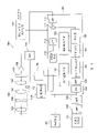
Fig. 1 is the block diagram that schematically shows according to the configuration of the camera head of the embodiment of the invention.
As shown in Figure 1, camera head 100 comprises: lens unit 130; CCD 135, are used for the target image that opto-electronic conversion is formed by lens unit 130; Analog part 136, it comprises CDS (correlated-double-sampling: circuit and AGC (automatic gain control: circuit Automatic Gain Control) Co-related Double Sampling), the signal that is obtained by CCD 135 is carried out predetermined processing, to generate the simulation image pickup signal; And camera signal treatment circuit 137, it comprises A/D converter, and the combine digital signal processing is to generate the vision signal of last output.These assemblies are by connected in series.Lens unit 130 comprises fixed lens group 131, variable focus lens package 132, shift lens group 133 and focusing offset lens group 134.
In addition, camera head 100 has: angular-rate sensor 101, be used to detect angular speed, i.e. and the shake of camera head is with the output angle rate signal; High pass filter (HPF) 102 is used to eliminate from the drift of the angular velocity signal of angular-rate sensor 101 outputs and the composition of other non-expectation; Amplifier 103 is used to amplify the angular velocity signal by after HPF 102 high-pass filterings; Camera arrangement control microcomputer (being designated hereinafter simply as " microcomputer ") 120 is used for the camera-enabled that control comprises jitter correction, automatic focusing (AF), zoom and automatic exposure (AE).These assemblies are by connected in series.
In addition, camera head 100 has: H bridge driver 114, pulse-width modulator (PWM) part 113 that it is connected to shift lens group 133 and will be referred to later; CCD drive circuit 138, it is connected to CCD 135 and the back shutter control section 121 with explanation, with drive controlling CCD 135; Position transducer 115 is used to detect the position of shift lens group 133; And amplifier 116, the A/D converter 117 that it is connected to position transducer 115 and will be referred to later.
In addition, microcomputer 120 comprises: A/D converter 117 is used for the output after being amplified by amplifier 116 is converted to digital signal, so that position data to be provided; Adder 111 is used to calculate poor between the current location of shift lens group 133 and the target drives value, to export actual correcting value; Low pass filter (LPF) 112 is used to reduce by H bridge driver 114 driving the driving noise that produces during the shift lens group 133; And PWM part 113, be used for pulse width modulation (PWM) is carried out in the output from LPF 112.These assemblies are by connected in series.
In addition, microcomputer 120 comprises: pan control section 122, it is connected to variable HP F 107 and integrator 108, changes threshold value and carries out pan control based on the cut-off frequency that the correction signal from integrator 108 outputs changes variable HPF 107 by pan is set according to shutter speed; And shutter control section 121, it is connected to pan control section 122 and C CD drive circuit 138, based on outputting video signal optimum shutter speed is set, thereby control CCD drive circuit 138 also will be sent to pan control section 122 about the information of current shutter speed from 137 outputs of camera signal treatment circuit.
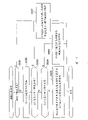
Fig. 2 is the flow chart that the pan control and treatment of being carried out by the camera head among Fig. 1 is shown.
As shown in Figure 2, at first, read in value of setting (step S201) of shutter speed, judge then whether this shutter speed is lower than first predetermined speed (step S202).Mainly based on lens focus, this first predetermined speed is set to such value: maybe this need not to carry out jitter correction more than value in this value.For example, if lens focus corresponding to the 250mm on 135 film cameras, then this first predetermined speed is set to 1/250 second shutter speed.
If shutter speed is not less than this first predetermined speed, if promptly shutter speed equals or faster than this first predetermined speed, then pan transformation threshold value is set to minimum value (step S203), and camera head 100 is set to general pan control characteristic (step S204).This general pan control characteristic is represented by the line chart among Fig. 3 (1), the cut-off frequency that this line chart (1) illustrates variable HPF 107 begins to rise at the time point that the correction angle surpasses the minimum value of pan transformation threshold value, in addition, when the correction angle has been increased to certain degree, make the slope of line chart (1) bigger, proofread and correct the end phenomenon thereby prevent to arrive.In Fig. 3, ordinate is represented the value of setting of HPF cut-off frequency in the pan control operation, and abscissa is represented by using from the correction signal of integrator 108 outputs and the jitter correction angle (jitter correction amount) of the calculating such as focal length of consideration lens unit 130.
If shutter speed is lower than this first predetermined speed, that is,, judge then whether shutter speed is not higher than second predetermined speed (step S205) if shutter speed is slower than this first predetermined speed.This second predetermined speed was set to lower shutter speed value for example 1/8 second, needed to estimate jitter correction undoubtedly in this value or when being lower than this value.
If shutter speed is not higher than second predetermined speed, then pan transformation threshold value is set to maximum (step S206), and camera head 100 is set to be used for the pan control characteristic (step S207) of low shutter speed.As a result, the pan control characteristic of camera head 100 is set to by the represented characteristic of the line chart among Fig. 3 (2).More specifically, pan transformation threshold value is set near proofreading and correct big fuzzy maximum correction angle (proofreading and correct end).When the correction angle surpassed the maximum of pan transformation threshold value, the cut-off frequency of variable HPF107 sharply increased, to suppress holding the unsuitable operation that causes because arrival is proofreaied and correct as much as possible.In addition, when the pan control characteristic is set to be used for the characteristic of low shutter speed,, suppress to proofread and correct the unsuitable operation that end causes owing to arriving by to being stored in the storage effect of image on long-time section (for example, 1/8 second) among the CCD 135.
If shutter speed is higher than second predetermined speed, then change the pan that the maximum of threshold value and minimum value that pan changes threshold value calculate after the interpolation from pan and change threshold value (step S208), the pan control characteristic is set so that make it be suitable for shutter speed (step S209) according to shutter speed.The pan control characteristic that is provided with according to shutter speed is by line chart (3) expression, as the intermediate characteristic between the represented characteristic in line chart (1) and (2).
The shutter speed that is read in step S201 is stored in the length of the time period among the CCD135 corresponding to image.Provide as shown in Figure 4 with the relevant data that respectively are worth of shutter speed to be used for interpolation, change threshold value, and can change threshold value by the supercomputing pan so that calculate pan.
In processing shown in Figure 2, owing to change pan control characteristic (step S203 and S204, step S206 and S207 and step S208 and S209) according to shutter speed, thereby in the influence of camera-shake subtle high-speed shutter operating period, make the transformation of pan control be easier to take place, and in the low speed shutter operation that the influence of camera-shake is easy to perceive, make the more difficult generation of transformation of pan control, thereby might strengthen anti-shake effect, therefore a kind of anti-shake effect that is suitable for shooting condition is provided.
In the processing of Fig. 2, set in advance the minimum value (step S203) of pan transformation threshold value, maximum (step S206) and the pan control characteristic (step S204 and S207) that pan changes threshold value explicitly with each predetermined value of shutter speed, and change threshold value (step S208) and pan control characteristic (step S209) by the interpolation calculation pan according to shutter speed.Yet this is not restrictive.For example, have following method: the value that the pan relevant with respectively being worth of shutter speed changes threshold value and pan control characteristic in microcomputer is set to tables of data, and reads pan according to shutter speed from set tables of data and change threshold value and pan control characteristic.Also can adopt and to make the optimum any other method of pan control according to shutter speed.
As an example, as shown in Figure 5, the relation that the pan according to the shutter speed setting can be changed between threshold value and the pan control characteristic is made table.This table is set in advance in microcomputer, and according to the value of the setting reading of data of shutter speed.Pan when to use Fig. 9 (abscissa is considered to representative and proofreaies and correct angle) to provide shutter speed here, be 1/60 second situation changes the explanation of threshold value and pan control characteristic.In this case, it is 0.14 degree that pan changes threshold value (some A), and width or distance between some A and the some B are 0.09 degree, and the slope of line chart is 0.8 in scope from point A to point B, and this slope is 2.0 in the scope that surpasses some B.The table that use is provided with in microcomputer like this makes may provide the control of the pan with pan control characteristic fixed with shutter speed.Should be noted in the discussion above that in Fig. 5 first predetermined speed is 1/250 second, second predetermined speed is 1/4 second.
Fig. 6 is the block diagram of configuration that schematically shows the variation of the camera head among Fig. 1.
Camera head among Fig. 6 have with Fig. 1 in the essentially identical configuration of camera head.Therefore, specify part and element by identical Reference numeral, and omit its repeat specification corresponding to the same components among Fig. 1, and only to Fig. 1 in the difference of camera head describe.
As shown in Figure 6, except components shown in Fig. 1 and element, camera head 100 also has releasing device 140.This releasing device 140 comprises release-push, when this release-push is pressed to the phase I, carries out same operation as shown in Figure 2.
Fig. 7 is the flow chart that the program of the pan control and treatment of being carried out by the camera head among Fig. 6 is shown.
As shown in Figure 7, at first, judge whether to have operated release-push (step S601).If operated release-push, then read in value of setting (step S602) of shutter speed, judge then whether shutter speed is not less than first predetermined speed (step S603).
If shutter speed is not less than first predetermined speed, then pan changes threshold value and is set to its minimum value, camera head 100 is set to general pan control characteristic (step S607), if and shutter speed is lower than first predetermined speed, judge then whether shutter speed is not higher than second predetermined speed (step S604).
If shutter speed is not higher than second predetermined speed, then pan changes threshold value and is set to its maximum, be set to be used for the characteristic (step S605) of low shutter speed with the pan control characteristic, if and shutter speed is higher than second predetermined speed, then the pan that calculates after the interpolation of the minimum and maximum value that changes threshold value from pan according to this shutter speed changes threshold value, and calculates the pan control characteristic (step S606) corresponding to this shutter speed.
On the other hand, if also do not operate release-push (step S601 not), then pan changes threshold value and is set to its minimum value, camera head 100 is set to general pan control characteristic (step S607).
According to the processing among Fig. 7, when camera head 100 is set to hang down shutter speed, before the operation release-push (step S601 denys), with identical under high shutter speed, carry out pan and change (step S607), behind the operation release-push, camera head 100 is set to be used for the pan control characteristic (step S605) of low shutter speed.Therefore, when ordinary circumstance, find a view even under low shutter speed, also can easily carry out, and when actual photographed, may strengthen anti-shake effect.
Although in the present embodiment, carry out pan control by basis from the cut-off frequency of the variable HPF107 of amplitude (correction angle) change of the output of integrator 108, also may carry out identical pan control by the integration constant that changes integrator 108.
Be to be understood that, purpose of the present invention also can be achieved like this: the storage medium that the program code of the software that stores the function that realizes the foregoing description is provided to system or device, make the computer (or CPU, or MPU) of this system or device read and carry out the program code that is stored in this storage medium.
In this case, the program code that is read from storage medium itself has been realized new function of the present invention, and therefore, program code and program code stored storage medium have constituted the present invention.
The example that is used to provide the storage medium of program code comprises: floppy disk, hard disk, magneto optical disk, CD be CD-ROM, CD-R, CD-RW, DVD-ROM, DVD-RAM, DVD-RW or DVD+RW, tape, non-volatile type storage card and ROM for example.Alternatively, can be by communication network download program code from server computer.
In addition, be to be understood that, not only can be by carrying out the function that the program code read be realized the foregoing description by computer, but also can wait instruction operating part or whole practical operation to realize by making operation OS (operating system) on computers based on program code.
In addition, be to be understood that, the function of the foregoing description also can be achieved like this: the program code that will read from storage medium is written to the memory of memory that inserts the expansion board in the computer or the functional expansion unit that is connected with computer, and instruction operating part or the whole practical operation based on program code such as the CPU that provides in expansion board or the functional expansion unit is provided then.
Claims (10)
1. camera head, when this camera head was in the pan state, it carried out pan control with predetermined pan control characteristic, and this camera head comprises:
The shutter speed setting device is used to be provided with the shutter speed that this camera head is operated when taking;
The shake checkout gear is used to detect the shake of camera head;
The correcting value calculation element is used to calculate the correcting value of the shake of camera head;
Blurring compensation device is used for the correcting value based on the shake of the camera head that is calculated, by driving the shake that corrective lens is proofreaied and correct camera head;
The pan judgment means is used for the correcting value based on the shake of set shutter speed and camera head, judges whether camera head is in the pan state; And
Pan control characteristic modifier is used for the correcting value based on the shake of set shutter speed and camera head, changes the pan control characteristic, wherein
When set shutter speed was slack-off, described pan judgment means did not judge that camera head is in the pan state, greatly ended up to the correction quantitative change of the shake of camera head.
2. camera head according to claim 1 is characterized in that, also comprises releasing device, and this releasing device comprises the release-push that uses when taking, and
Wherein, behind the described release-push of operation, described pan judgment means judges based on the correcting value of the shake of set shutter speed and camera head whether camera head is in the pan state, till the operation of the described release-push of cancellation.
3. camera head according to claim 1 is characterized in that, described pan control characteristic is arranged so that the cut-off frequency that uses in the pan control uprises with the increase of the correcting value of the shake of camera head.
4. camera head according to claim 3 is characterized in that set shutter speed is slow more, and the cut-off frequency that uses in pan control is big more with respect to the increase speed of the correcting value of the shake of camera head.
5. camera head according to claim 3 is characterized in that, when correcting value equals predetermined value, changes the increase speed of the cut-off frequency of use in pan control with respect to the correcting value of the shake of camera head.
6. image capture method that is used for camera head, when this camera head was in the pan state, it carried out pan control with predetermined pan control characteristic, and this image capture method comprises:
Shutter speed is provided with step, is used to be provided with the shutter speed of this camera head operation when taking;
Shake detects step, is used to detect the shake of camera head;
The correcting value calculation procedure is used to calculate the correcting value of the shake of camera head;
The jitter correction step is used for the correcting value based on the shake of the camera head that is calculated, by driving the shake that corrective lens is proofreaied and correct camera head;
The pan determining step is used for the correcting value based on the shake of set shutter speed and camera head, judges whether camera head is in the pan state; And
The pan control characteristic changes step, is used for the correcting value based on the shake of set shutter speed and camera head, changes the pan control characteristic, wherein
When set shutter speed is slack-off, in described pan determining step, do not judge that camera head is in the pan state, greatly end up to the correction quantitative change of the shake of camera head.
7. the image capture method that is used for camera head according to claim 6, it is characterized in that, described pan determining step comprises: behind the release-push that uses when operation is taken, correcting value based on the shake of set shutter speed and camera head, judge whether camera head is in the pan state, till the operation of the described release-push of cancellation.
8. the image capture method that is used for camera head according to claim 6 is characterized in that, described pan control characteristic is arranged so that the cut-off frequency that uses in pan control uprises with the increase of the correcting value of the shake of camera head.
9. the image capture method that is used for camera head according to claim 8 is characterized in that set shutter speed is slow more, and the cut-off frequency that uses in pan control is big more with respect to the increase speed of the correcting value of the shake of camera head.
10. the image capture method that is used for camera head according to claim 8 is characterized in that, when correcting value equals predetermined value, changes the increase speed of the cut-off frequency of use in pan control with respect to the correcting value of the shake of camera head.
Applications Claiming Priority (2)
| Application Number | Priority Date | Filing Date | Title |
|---|---|---|---|
| JP2005016134A JP4642489B2 (en) | 2005-01-24 | 2005-01-24 | Imaging apparatus, imaging method, imaging program, and storage medium |
| JP2005016134 | 2005-01-24 |
Publications (2)
| Publication Number | Publication Date |
|---|---|
| CN1812501A CN1812501A (en) | 2006-08-02 |
| CN100403776C true CN100403776C (en) | 2008-07-16 |
Family
ID=36097244
Family Applications (1)
| Application Number | Title | Priority Date | Filing Date |
|---|---|---|---|
| CNB2006100016842A Expired - Fee Related CN100403776C (en) | 2005-01-24 | 2006-01-24 | Image pickup apparatus and image pickup method |
Country Status (6)
| Country | Link |
|---|---|
| US (1) | US7496289B2 (en) |
| EP (1) | EP1684502B1 (en) |
| JP (1) | JP4642489B2 (en) |
| KR (1) | KR100731193B1 (en) |
| CN (1) | CN100403776C (en) |
| DE (1) | DE602006001212D1 (en) |
Families Citing this family (16)
| Publication number | Priority date | Publication date | Assignee | Title |
|---|---|---|---|---|
| US7791643B2 (en) * | 2005-01-28 | 2010-09-07 | Hewlett-Packard Development Company, L.P. | Sequenced response image stabilization |
| JP2007199182A (en) * | 2006-01-24 | 2007-08-09 | Pentax Corp | Camera with vibration-proof function |
| JP4853320B2 (en) * | 2007-02-15 | 2012-01-11 | ソニー株式会社 | Image processing apparatus and image processing method |
| JP2008225550A (en) * | 2007-03-08 | 2008-09-25 | Sony Corp | Image processing apparatus, image processing method and program |
| JP4424364B2 (en) * | 2007-03-19 | 2010-03-03 | ソニー株式会社 | Image processing apparatus and image processing method |
| JP4396720B2 (en) * | 2007-03-26 | 2010-01-13 | ソニー株式会社 | Image processing apparatus, image processing method, and program |
| JP2009003334A (en) * | 2007-06-25 | 2009-01-08 | Sony Corp | Image pick-up device, and imaging control method |
| US7986178B2 (en) * | 2007-12-14 | 2011-07-26 | Supertex, Inc. | Pulse width modulation driver for electroactive lens |
| JP4986175B2 (en) * | 2007-12-28 | 2012-07-25 | カシオ計算機株式会社 | Imaging apparatus and program |
| JP5031690B2 (en) * | 2008-07-15 | 2012-09-19 | キヤノン株式会社 | Anti-vibration control device, imaging device, and control method for image stabilization control device |
| JP5501119B2 (en) * | 2010-06-29 | 2014-05-21 | キヤノン株式会社 | Imaging apparatus and control method thereof |
| TWI441515B (en) * | 2010-09-15 | 2014-06-11 | Altek Corp | Photographic device with an optical anti-shake module and optical anti-shake photographic device with a peripheral driver chip |
| JP5869812B2 (en) * | 2011-09-13 | 2016-02-24 | キヤノン株式会社 | Image blur correction apparatus, image pickup apparatus including the same, and method for controlling image blur correction apparatus |
| JP5736512B2 (en) * | 2012-06-22 | 2015-06-17 | 富士フイルム株式会社 | Imaging apparatus and operation control method thereof |
| JP6581352B2 (en) * | 2014-03-05 | 2019-09-25 | キヤノン株式会社 | Image blur correction apparatus and control method thereof, imaging apparatus, lens apparatus, program, and storage medium |
| JP2017191140A (en) * | 2016-04-11 | 2017-10-19 | キヤノン株式会社 | Imaging apparatus and control method of the same |
Citations (4)
| Publication number | Priority date | Publication date | Assignee | Title |
|---|---|---|---|---|
| US5262820A (en) * | 1991-05-27 | 1993-11-16 | Minolta Camera Kabushiki Kaisha | Camera having a blur detecting device |
| US5761545A (en) * | 1992-02-06 | 1998-06-02 | Nikon Corporation | Pan shot device for a camera |
| US20020027599A1 (en) * | 2000-08-31 | 2002-03-07 | Tatsuya Yamazaki | Blur correction apparatus, control apparatus to be used in a blur correction apparatus, image taking apparatus, control method to be used in these apparatuses and computer program product to be used with these apparatuses |
| US6445411B1 (en) * | 1997-03-14 | 2002-09-03 | Canon Kabushiki Kaisha | Camera control system having anti-blur facility |
Family Cites Families (12)
| Publication number | Priority date | Publication date | Assignee | Title |
|---|---|---|---|---|
| JPH02151180A (en) * | 1988-12-02 | 1990-06-11 | Canon Inc | Image pickup device |
| JPH11168657A (en) * | 1997-12-05 | 1999-06-22 | Sony Corp | Image-pickup device |
| US6982746B1 (en) * | 1998-02-24 | 2006-01-03 | Canon Kabushiki Kaisha | Apparatus and method for correcting shake by controlling sampling timing of shake signal |
| JP2001028708A (en) | 1999-07-13 | 2001-01-30 | Canon Inc | Image pickup system and method |
| JP2004000720A (en) * | 2000-05-31 | 2004-01-08 | Namco Ltd | Game system, program, and information storage medium |
| JP3740398B2 (en) * | 2000-08-31 | 2006-02-01 | キヤノン株式会社 | Shake correction device, control device applied to shake correction device, control method applied to shake correction device, control program applied to shake correction device, imaging device |
| JP2002209136A (en) | 2001-01-05 | 2002-07-26 | Canon Inc | Photographing device |
| JP3897993B2 (en) | 2001-05-30 | 2007-03-28 | 松下電器産業株式会社 | Imaging apparatus, image correction method, program, and recording medium |
| JP2003333438A (en) | 2002-05-14 | 2003-11-21 | Matsushita Electric Ind Co Ltd | Image motion correcting device |
| JP3951177B2 (en) | 2002-10-22 | 2007-08-01 | フジノン株式会社 | Image blur correction device |
| JP2004228809A (en) * | 2003-01-21 | 2004-08-12 | Canon Inc | Imaging apparatus |
| JP2006080837A (en) | 2004-09-09 | 2006-03-23 | Canon Inc | Image pickup device |
-
2005
- 2005-01-24 JP JP2005016134A patent/JP4642489B2/en not_active Expired - Fee Related
-
2006
- 2006-01-23 EP EP06250347A patent/EP1684502B1/en not_active Expired - Fee Related
- 2006-01-23 DE DE602006001212T patent/DE602006001212D1/en active Active
- 2006-01-23 US US11/337,288 patent/US7496289B2/en not_active Expired - Fee Related
- 2006-01-24 CN CNB2006100016842A patent/CN100403776C/en not_active Expired - Fee Related
- 2006-01-24 KR KR1020060007288A patent/KR100731193B1/en not_active IP Right Cessation
Patent Citations (4)
| Publication number | Priority date | Publication date | Assignee | Title |
|---|---|---|---|---|
| US5262820A (en) * | 1991-05-27 | 1993-11-16 | Minolta Camera Kabushiki Kaisha | Camera having a blur detecting device |
| US5761545A (en) * | 1992-02-06 | 1998-06-02 | Nikon Corporation | Pan shot device for a camera |
| US6445411B1 (en) * | 1997-03-14 | 2002-09-03 | Canon Kabushiki Kaisha | Camera control system having anti-blur facility |
| US20020027599A1 (en) * | 2000-08-31 | 2002-03-07 | Tatsuya Yamazaki | Blur correction apparatus, control apparatus to be used in a blur correction apparatus, image taking apparatus, control method to be used in these apparatuses and computer program product to be used with these apparatuses |
Also Published As
| Publication number | Publication date |
|---|---|
| US7496289B2 (en) | 2009-02-24 |
| US20060165396A1 (en) | 2006-07-27 |
| CN1812501A (en) | 2006-08-02 |
| EP1684502A1 (en) | 2006-07-26 |
| KR100731193B1 (en) | 2007-06-22 |
| JP2006201723A (en) | 2006-08-03 |
| KR20060085598A (en) | 2006-07-27 |
| JP4642489B2 (en) | 2011-03-02 |
| EP1684502B1 (en) | 2008-05-21 |
| DE602006001212D1 (en) | 2008-07-03 |
Similar Documents
| Publication | Publication Date | Title |
|---|---|---|
| CN100403776C (en) | Image pickup apparatus and image pickup method | |
| JP5230398B2 (en) | Imaging apparatus and control method thereof | |
| JP4072348B2 (en) | Shake correction device, imaging device, shake correction method, shake correction device control program, and storage medium | |
| JP5328307B2 (en) | Image capturing apparatus having shake correction function and control method thereof | |
| JP5409342B2 (en) | Imaging apparatus and control method thereof | |
| JP6101074B2 (en) | Optical apparatus, image blur correction apparatus, imaging apparatus, control method therefor, program, and storage medium | |
| JP4306679B2 (en) | Shake detection device, shake correction device, imaging device | |
| JP7058945B2 (en) | Image stabilization device and its control method, image pickup device | |
| JP6821358B2 (en) | Control device, image pickup device, lens device, control method, program, and storage medium | |
| JP6598537B2 (en) | Image processing apparatus, imaging apparatus, and image processing program | |
| JP2015180917A (en) | Image blur correction device, control method of the same, imaging device, lens device, program, and storage medium | |
| CN108668074B (en) | Image blur correction device, control method thereof, image pickup apparatus, and storage medium | |
| JP5426952B2 (en) | Image shake correction apparatus, control method therefor, optical apparatus, and imaging apparatus | |
| JP2018072540A (en) | Image processing device, image processing method, and optical apparatus | |
| JP6039212B2 (en) | Image blur correction apparatus, imaging apparatus, and image blur correction apparatus control method | |
| US20140125826A1 (en) | Image capturing apparatus and method of controlling image capturing apparatus | |
| JP4536855B2 (en) | Anti-vibration device, imaging device, and control method of anti-vibration device | |
| JP2008187617A (en) | Imaging apparatus, control method of imaging apparatus, and control program for imaging apparatus | |
| JP2012237770A (en) | Imaging apparatus and lens barrel | |
| JP2002207232A (en) | Method and apparatus for correcting image blur of image pickup device | |
| JP2017135515A (en) | Imaging apparatus and control method of the same | |
| JP2006203493A (en) | Image movement correction device | |
| JP2020148999A (en) | Control device, imaging device, lens device, control method, and program | |
| JP6541368B2 (en) | Image blurring correction apparatus, optical apparatus, imaging apparatus and control method | |
| JP2005099785A (en) | Automatic focusing device |
Legal Events
| Date | Code | Title | Description |
|---|---|---|---|
| C06 | Publication | ||
| PB01 | Publication | ||
| C10 | Entry into substantive examination | ||
| SE01 | Entry into force of request for substantive examination | ||
| C14 | Grant of patent or utility model | ||
| GR01 | Patent grant | ||
| CF01 | Termination of patent right due to non-payment of annual fee |
Granted publication date: 20080716 Termination date: 20180124 |
|
| CF01 | Termination of patent right due to non-payment of annual fee |