CN100410681C - Nuclear magnetic resonance pulse sequence for nuclear magnetic resonance device having relative moving with sample - Google Patents
Nuclear magnetic resonance pulse sequence for nuclear magnetic resonance device having relative moving with sample Download PDFInfo
- Publication number
- CN100410681C CN100410681C CNB2004100699366A CN200410069936A CN100410681C CN 100410681 C CN100410681 C CN 100410681C CN B2004100699366 A CNB2004100699366 A CN B2004100699366A CN 200410069936 A CN200410069936 A CN 200410069936A CN 100410681 C CN100410681 C CN 100410681C
- Authority
- CN
- China
- Prior art keywords
- pulse
- sequence
- saturated
- nmr
- sample
- Prior art date
- Legal status (The legal status is an assumption and is not a legal conclusion. Google has not performed a legal analysis and makes no representation as to the accuracy of the status listed.)
- Expired - Fee Related
Links
Images


Classifications
-
- G—PHYSICS
- G01—MEASURING; TESTING
- G01V—GEOPHYSICS; GRAVITATIONAL MEASUREMENTS; DETECTING MASSES OR OBJECTS; TAGS
- G01V3/00—Electric or magnetic prospecting or detecting; Measuring magnetic field characteristics of the earth, e.g. declination, deviation
- G01V3/18—Electric or magnetic prospecting or detecting; Measuring magnetic field characteristics of the earth, e.g. declination, deviation specially adapted for well-logging
- G01V3/32—Electric or magnetic prospecting or detecting; Measuring magnetic field characteristics of the earth, e.g. declination, deviation specially adapted for well-logging operating with electron or nuclear magnetic resonance
-
- G—PHYSICS
- G01—MEASURING; TESTING
- G01N—INVESTIGATING OR ANALYSING MATERIALS BY DETERMINING THEIR CHEMICAL OR PHYSICAL PROPERTIES
- G01N24/00—Investigating or analyzing materials by the use of nuclear magnetic resonance, electron paramagnetic resonance or other spin effects
- G01N24/08—Investigating or analyzing materials by the use of nuclear magnetic resonance, electron paramagnetic resonance or other spin effects by using nuclear magnetic resonance
- G01N24/081—Making measurements of geologic samples, e.g. measurements of moisture, pH, porosity, permeability, tortuosity or viscosity
Abstract
A method and an apparatus for obtaining NMR measurements are disclosed. An NMR measurement apparatus, the measured sample, or both elements may be subjected to motion during the measurement. The envelope of an RF carrier signal is modulated according to an envelope to generate a first sequence of RF pulses. The envelope, the phase of the RF signal, and/or a static magnetic field may be varied during the radiation of the first sequence to substantially saturate a first region of the sample. The first sequence may include additional RF refocusing pulses that, when coupled with movement of the NMR measurement apparatus or sample, may also be used to substantially saturate the first region. A second sequence of RF pulses is radiated to establish a resonance region within the first region and measure an attribute of the sample.
Description
Technical field
The present invention relates generally to pre-service near the spin nuclear magnetic resonance (NMR) zone.
Background technology
Nuclear magnetic resonance (NMR) can be used for measuring the characteristic such as the sample of body tissue (for the purpose of medical imaging) or subsurface formations structure (for the purpose of recorded downhole).For example, for the subsurface formations structure, can use factor of porosity, stratigraphic structure type, permeability and oil mass that NMR measured and drew stratigraphic structure.
With reference to the accompanying drawings 1, as an example, in limit writing edge drilling well (LWD) operation, use the performance plot that NMR draws subsurface formations structure 10.Here, becoming axisymmetric NMR well logger 6 is parts of drill string 5, uses this drill string 5 and bore a wellhole 3 on stratum 10.For example, well logger 6 can be that people such as Sezginer are in U.S. Patent No. 5,705,925 (mandates on January 6th, 1998, be entitled as " Pulsed Nuclera Magnetism Tool For FormationEvalution While Drilling Including a Shortened or Truncated CPMGSequence ") in or Miller in U.S. Patent No. 5,280, one of well logger described in 243 (on January 18th, 1994 authorized, and was entitled as " System For Logging a Well During the DrillingThereof ").
Compare with other most of down-hole formation structure measuring methods, the NMR measuring method has two obvious characteristics.At first, be from a less resonant space from the NMR signal on stratum, such as being generally a thin resonant space 20a (referring to accompanying drawing 2), the radial thickness of resonant space 20a and magnetic field
 Being in proportion of (not shown).For example, depend on the shape of different resonance zones, this space can reach several feet little an extension to 1 millimeter (mm) and in another direction of direction.The second, it can not be instantaneous that NMR measures.As hereinafter further describing, make the NMR well logger be easy to carry out traverse measurement in conjunction with these 2 facts, move around
 wellhole 3 such as NMR well logger 6.
As mentioned below, to measure in order to carry out NMR, NMR well logger 6 comprises setting up and is called
The static magnetic field (not shown) permanent magnet, the emission perpendicular to magnetic field
 Time-varying magnetic field
 Radio frequency (RF) coil or antenna and reception from measuring the RF coil or the antenna of the spin echo of corresponding stratigraphic structure with NMR.And these two coils can be combined in the single transmit/receive antenna.
As an example, detect sequence so that atomic nucleus produces spin echo by emission NMR, NMR well logger 6 is measured the spin-spin relaxation time T 2 of the hydrogen nuclei of stratigraphic structure 10.Analyze the distribution that spin echo obtains time T 2 successively, from this distribution, can obtain the characteristic of stratigraphic structure.For example, a kind of NMR that comes to this of Carr-Purcell-Meiboom-Gill (CPMG) sequence 15 described in the accompanying drawing 4 detects sequence.Application sequence 15 can obtain the distribution of time T 2, and can use the characteristic that stratigraphic structure 10 was measured and drawn in this distribution.
Using cpmg sequence row 15 comes the technology of Measuring Time T2 to comprise following step.In the first step, NMR well logger 6 is launched magnetic field with the suitable time interval
 Make spin (the initial and magnetic field of hydrogen nuclei to use 90 ° of driving
 pulse 14a
 The direction unanimity) half-twist.Though do not illustrate, in fact each pulse all is the envelope or the train of impulses of RF carrier signal.Spinning from magnetic field
 Behind the direction half-twist, at first the spin begin immediately with magnetic field
 Precession as one man in the vertical plane then little by little loses synchronously.In second step, in a
 NMR pulse 14a set time T subsequently, NMR well logger 6 applies magnetic field with the form of pulse
 And continue a long period section (with
 NMR pulse 14a relatively), to use 180 ° of additional angle of spin that NMR refocusing pulse 14b rotates precession, make simultaneously its carrier phase move ± 90 °.NMR pulse 14b makes spin synchronous again, and makes emission one auxiliary spin echo (seeing accompanying drawing 5) after being spun on 180 ° of refocusing pulse 14b, and the time to peak of this spin echo approximates T greatly.With interval t
e(being roughly 2T) repeating step 2 " k " inferior (" k " is called number of echoes here, for example, can suppose from hundreds of to any one value that reaches several thousand).For third step, after finishing spin-echo sequence, before next cpmg sequence row 15 beginning of assembling another sequence spin echo, require, so that spin turns back to along magnetic field through a wait cycle (being commonly referred to the stand-by period)
 Equilibrium state.Observe the decay of each spin-echo sequence and derive the distribution of T2 with it.


As indicated above, the characteristic of stratigraphic structure is measured in the distribution that can use the T2 time.For example, with reference to the accompanying drawings 6, the stratum may comprise the aperture that accommodates constrain fluids and accommodate freely, the macropore of recoverable fluid.Can use separate confinement time T 2 and (in accompanying drawing 6, be called as T
CUT-DFF) T2 is divided into two parts: a part comprises and compares T
CUT-OFFA little time (expression constrain fluids) and a part comprise and compare T
CUT-OFFThe big time (expression freely, recoverable fluid).
Usually, come T2 computing time by the decay of observing the spin echo 16 that produces by specific cpmg sequence row 15.Unfortunately, drill string 5 (referring to accompanying drawing 1) passes through violent transverse movement possibly.Yet time T 2 is roughly proportional with the time constant that another is called as SPIN LATTICE relaxation time T1.Time T 1 has the spin of making along magnetic field
Direction turns back to the characteristic of equilibrium state again, thus, considers two T1 and T2 time, can think that each moves towards the equilibrium position with utmost point helical motion form closely from being spun in the T1 rejuvenation.Fortunately, time T 1 and T2 are roughly proportional.Therefore, the distribution that can derive time T 2 from the time T of measuring 1.In fact, the initial work application T1 that sets up the constrain fluids cut off finishes.According to T2 these expression of results are come out then and be applied in commercial.Referring to W.E.Kenyon, J.J.Howard, A.Sezginer, C.Straley, A.Matteson, K.Horkowtitz, and R.Ehrlich waits people's Pore-Size Distribution and NMR in Microporous ChertySandstones, and paper LL (goes up the paper of submitting in the 30th year record symposial (the 30th AnnualLogging Symposium), SWPLA, 11-14 day in June, 1989).
Measurement based on polarization can be used inversion recovery sequence (inversion recoverysequence) or saturation recovery sequence (saturation recovery sequence).Under saturation recovery sequence situation, for example use and severally the magnetization is reduced to 90 ° of pulses of zero makes spin system saturated.Make spin system recover to reach the time of a variable-length before in application monitoring pulse or pulse train (such as the cpmg sequence row) then.Oppositely recovery technology require the spin of atomic nucleus itself with the static magnetic field being aligned after use 180 ° of pulses make spin reverse.Along with the past of time, spin decays towards the balance direction according to T1, but because 180 ° of pulses do not produce signal in detecting device, does not measure.Yet before decay was finished, monitoring pulse or pulse train (such as the cpmg sequence row) had been interrupted decay, and this monitoring pulse or pulse train rotate to measurement plane (that is, producing signal in detecting device) with spin.Significant information is exactly the signal amplitude after initial 90 ° of " reading " pulse moments.This amplitude places one's entire reliance upon the release time between initial 180 ° of pulses and 90 ° of pulses.Next measure amplitude, allow the complete relaxation of spin system to equilibrium state, repetition pulse sequence then.
Be described in people's such as Kleinberg U.S. Patent No. 5 at the example of down-hole application as inversion recovery sequence, 023, in 551 (be entitled as " Nuclear Magnetic Resonance PulseSequences For Use With Borehole Logging Tools ", on June 11st, 1991 authorized).Yet inversion recovery sequence in ' 551 that are described in United States Patent (USP) can not be used adiabatic pulse, causes thus only surveying in a narrow region.In addition, under the situation that has mobile and " surveying outside the interior inspection ", make a regional saturation ratio that its complete anti-phase recovery is wanted easily.Therefore, more desirable way is to make the zone saturated.
Back with reference to the accompanying drawings 2, usually, use based on the measurement of polarization and do not use the measurement based on decay as described above and come Measuring Time T1.In measurement based on polarization, each measurement based on polarization at first comprise use saturated sequence make resonance zone (such as, at the cylindrical resonant space 20a described in the accompanying drawing 2) in spin arrive saturated step.Then, through a polarization time resonant space 20a is polarised to static magnetic field
 Subsequently, applying detection sequence (such as the cpmg sequence row) is to produce the spin echo from stratigraphic structure 10.Then, analyze the amplitude of a few spin echo that begins to determine the polarization weighting integer Φ (t of distribution of porosity Φ (T1)
Wit).Because, only need a few echo of observation beginning just can determine the amplitude of signal, thus can in than the duration shorter, measure T1 based on the required time of attenuation measurement T2, thereby, more be not suitable for mobile NMR well logger 6 when measuring T1.Repeat (after suitable saturated sequence) continuously with the different stand-by period and detect sequence several times to obtain distribution of porosity Φ (T1).
Subsequently, applying detection sequence (such as the cpmg sequence row) is to produce the spin echo from stratigraphic structure 10.Then, analyze the amplitude of a few spin echo that begins to determine the polarization weighting integer Φ (t of distribution of porosity Φ (T1)
Wit).Because, only need a few echo of observation beginning just can determine the amplitude of signal, thus can in than the duration shorter, measure T1 based on the required time of attenuation measurement T2, thereby, more be not suitable for mobile NMR well logger 6 when measuring T1.Repeat (after suitable saturated sequence) continuously with the different stand-by period and detect sequence several times to obtain distribution of porosity Φ (T1).
As an example, use based on the measurement of polarization and measure time T 1 at the hydrogen nuclei that is arranged in the resonant space 20a of saturated space 20b (referring to accompanying drawing 2).Here, it is saturated that NMR well logger 6 at first makes the spin in saturated space 20b.Yet the polarization time should can be done to move fully in wellhole to allow NMR well logger 6 by long enough.In this case, the mobile resonant space 20a that makes of NMR well logger 6 moves, so that NMR well logger 6 receives from the spin echo among the resonant space 20a ' (referring to accompanying drawing 3) that has moved, this resonant space 20a ' part is fallen outside the initial saturated space 20b.As a result, the resonant space 20a ' that has moved comprises that one does not have the zone (being commonly referred to as " moving into spin newly " effect) and of saturated spin to have the subregion of the initial saturated space 20b of saturated spin.New spin unfortunately, do not allow in the polarization time, to move into " new spin ", because may be introduced measuring error based on the NMR technology that polarizes.For example, measure the indication of possible errors ground the more constrained flow scale of construction that occurs than reality is arranged in stratigraphic structure.
Be to have described a kind of saturated a kind of method in bigger zone that makes in the PCT application (being entitled as " Method ForFormation Evaluation While Drilling ", application on Dec 29th, 1997) of PCT/US97/23975 at application number.This application is pointed out, when measuring beginning, emission covers one or more pulses that one or more radio-frequency pulses of a relatively large frequency range and/or wide especially bandwidth or application have the saturated sweep frequency of the cylindrical space that can make around the NMR well logger.This application further described when since well logger move and exceed the zone of saturation and cause that measuring when invalid the applied acceleration peak value measures.This application also further describes on well logger the equipment bearing and exceeds the zone of saturation to stop well logger to move.
Therefore, people thirst for will be at the error minimize that relatively moves and cause between NMR measurement mechanism and the sample that is surveyed always.
Summary of the invention
The invention discloses a kind of for the method that the NMR measurement mechanism use that relatively moves is arranged between device and sample.Device, sample or the two all may move.In one embodiment of the invention, this method comprises emission the one RF pulse train.First sequence has envelope.During emission first sequence, change envelope, so that the first area of sample is saturated substantially.Launch the 2nd RF pulse train in the first area, setting up resonance zone, and measure the attribute of sample.
In another embodiment, comprise that for the method that the NMR measurement mechanism use that relatively moves is arranged using the RF carrier signal launches a RF pulse train between device and sample.This carrier signal has a phase place.During emission first sequence, change envelope, so that the first area of sample is saturated substantially.Launch the 2nd RF pulse train in the first area, setting up resonance zone, and measure the attribute of sample.
In another embodiment, between device and sample, there is the NMR measurement mechanism that relatively moves to comprise that at least one sets up the magnet of static magnetic field, one first coil, one second coil and a pulse producer.Pulse producer is connected with second coil with first coil, and makes it be suitable for using first coil to launch a RF pulse train to produce a time-varying magnetic field.First sequence comprises that at least one refocusing pulse is to produce at least one echo from the resonance zone of sample.Use second coil in pulse producer also is suitable for during emission first sequence and come to change at least momently static magnetic field once so that a regional saturation degree is bigger than resonance zone.
In a further embodiment, a kind ofly comprise the application inversion recovery sequence for the method that has the NMR measurement mechanism that relatively moves to use between device and sample, this comprises at least one or a plurality of adiabatic pulse this inversion recovery sequence.
According to a kind of method that is used for the NMR measurement mechanism of wellhole of the present invention, between the sample of this device and stratigraphic structure, relatively move, this method comprises:
A) produce a static magnetic field;
B) emission the one RF pulse train;
C) in the emission process of said first sequence, change a parameter so that the first area of the sample of stratigraphic structure is saturated substantially; With
D) emission the 2nd RF pulse train is so that set up resonance zone in the first area; With
E) characteristic of measurement sample.
In addition, according to a kind of method that is used for the NMR measurement mechanism of wellhole of the present invention, relatively move between the sample of this device and stratigraphic structure, this method comprises::
A) produce a static magnetic field;
B) emission the one RF pulse train, this first sequence comprises at least one refocusing pulse, this pulse produces at least one echo from the resonance zone of the sample of stratigraphic structure;
C) during the emission of described sequence, change described static electric field at least once, so that make the regional saturated of the stratigraphic structure bigger than resonance zone; With
D) characteristic of the sample of measurement stratigraphic structure.
In addition,, between the sample of this device and stratigraphic structure, relatively move, comprising according to a kind of NMR measurement mechanism that is used for wellhole of the present invention:
A) at least one magnet;
B) at least one coil; With
C) pulse producer that links to each other with coil, this pulse producer is suitable for:
I) launch a RF pulse train by said coil;
Ii) change a parameter so that the first area of the sample of stratigraphic structure is saturated substantially in the emission process of said first sequence, wherein said parameter is the envelope of said sequence or the phase place of RF carrier signal;
Iii) launch the 2nd RF pulse train, in said first area, set up resonance zone by said coil; With
Iv) measure the characteristic of sample.
Description of drawings
By following detailed, it is clearer that other embodiments of the invention will become.
Accompanying drawing 1 is the synoptic diagram of missile silo.
Accompanying drawing 2 is the cross-sectional view of the well of the 2-2 line in the accompanying drawing 1.
Accompanying drawing 3 is another cross-sectional view of the well after the NMR well logger moves.
Attached Figure 4 and 5 are the waveform of CPMG pulse train.
Accompanying drawing 6 is the distribution example of relaxation time T2.
Accompanying drawing 7 be according to one embodiment of the present of invention based on the polarization measurement process flow diagram.
Accompanying drawing 8,9 and 10 is the synoptic diagram according to the NMR well logger of different embodiment of the present invention.
Accompanying drawing 11 is the cross-sectional view of the NMR well logger of the 11-11 line in the accompanying drawing 10.
Accompanying drawing 12 is the waveform of NMR pulse train.
Accompanying drawing 13,16,18 and 20 is depicted as the saturated isogram of resonance zone.
Accompanying drawing 14,15,17 and 19 and 21 is depicted as from the zone of saturation on every side of NMR well logger and receives the contrast signal amplitude figure of coming.
Accompanying drawing 22 and 23 is depicted as the saturated isoline of resonance zone when using the pulse have with the different numbers of staggered Free Development time not.
Accompanying drawing 24 and 25 is depicted as the saturated isoline of resonance zone when using the pulse have with the different numbers of staggered Free Development time not.
Embodiment
With reference to the accompanying drawings 7, the NMR measurement mechanism that is easy to move (for example NMR well logger) can be used according to the present invention and realize the method example 50 measured based on polarized T 1.Because measured sample may move,, can use this measuring method when sample, measurement mechanism or both have when mobile.Method 50 comprises the step (piece 52) that the spin in the zone that makes in the sample is saturated, and this sample is the sample that will measure its characteristic; Then, through preset time at interval (piece 54), so that the spin generation partial polarization in this zone at least; Subsequently, method 50 comprises that application (piece 56) detects the step of sequence (for example, based on CPMG sequence) to produce the spin echo from the resonance zone of sample.As hereinafter further describing, when the NMR measurement mechanism has moved, use some technology and make the border of zone of saturation and saturated density maximum so that resonance zone remains in the zone of saturation substantially.The technology of using these can reduce measuring error, and (for example) do not need the NMR measurement mechanism is carried out stable stabilising arrangement if when being applied in the geometry of less gradient.
For example, as hereinafter further describing in more detail, measuring method 50 can be used to draw the characteristic of subsurface formations structure, and also can be applied to other between sample and NMR measurement mechanism, produce in the application that relatively moves (such as, the NMR of other " the outer survey type of interior inspection " uses).In certain embodiments, the NMR measurement mechanism may comprise the electromagnetic field producing component (such as, a coil, an electromagnet and a permanent magnet) to produce at least two magnetic fields: one is called
 Magnetic field (not shown) and one and magnetic field
 Substantially vertical is called
 The magnetic field (not shown).With reference to the accompanying drawings 8, for example, in certain embodiments, the NMR measurement mechanism may be the
 well logger 60 of drilling well limit, NMR limit record (LWD), and for example, this well logger 60 comprises sets up magnetic field
 Belt
Belt permanent magnet 32 and 34 and set up time-varying magnetic field
 Coil 39.In certain embodiments, magnetic field
 May (when applying pulse) have and be called
Radio frequency (RF) carrier component.
May (when applying pulse) have and be called
Radio frequency (RF) carrier component.
Magnetic field
Carrier frequency generally with ω
0Expression.Emission magnetic field
 Generation one has the resonance zone of certain radial thickness, and according to frequency, this radial thickness is by the ω in excitation area
0And ω
1Gradient decision, here
Generation one has the resonance zone of certain radial thickness, and according to frequency, this radial thickness is by the ω in excitation area
0And ω
1Gradient decision, here
 Be γ
In magnetic field
On projection.In certain embodiments, as mentioned below, magnetic field
Be γ
In magnetic field
On projection.In certain embodiments, as mentioned below, magnetic field
 Also may produce (at least in part), so that magnetic field by
 gradient coil 40 and 42
Has a component along with low frequency variations.NMR well logger 60 also may comprise treatment circuit, and this treatment circuit comprises such as being connected to coil () pulse producer 65 for example, coil 39,40 and 42, and be suitable for launching magnetic field in the mode that hereinafter will describe
And/or magnetic field

Substantially, each NMR based on polarization measures and comprises three calibrated bolcks 52,54 and 56 (referring to accompanying drawing 7), and can adopt the one or many measurement to obtain each T1 value.Yet, can the applying detection sequence (promptly, piece 52) realize saturated (promptly, the function of execution block 56), therefore, if satisfied two conditions: duplicate measurements continuously (being called " (stacked) in heaps " test) and signal detection sequence 68 can be eliminated fully to carrying out the magnetization of next step measurement, just can cancel piece 52.If use this technology, then abandon from the result in measuring for the first time, because measurement was carried out with an incorrect polarization time for the first time.As a kind of modification, only before the applying detection sequence, encourage by in resonance zone, using adiabatic transition (passage) pulse fast adiabaticly.
Three fundamental blocks 52,54 and 56 also have other modification.As the another one example, order piece 54---piece 56---piece 52 can be used for carrying out each measurement, and this modification is more excellent from the programming angle.When using second kind of modification, abandon measuring for the first time.All belong to possibility as long as realized other modification of the functional method 50 of piece 52,54 and 56.
No matter be by explicit saturated sequence or or to carry out saturated, saturated purpose all be to make a bigger zone or space saturated by radio frequency (RF) emission by detecting sequence.As hereinafter more detailed description and simulated experiment show, according to certain embodiments, it is saturated to select following mode to realize: use RF pulse train (detecting sequence such as CPMG), this sequence is to be suitable for using moving of NMR well logger 60 to reach required state of saturation; No matter NMR well logger 60 has or does not have to move the time response that all slowly changes sequence; No matter NMR well logger 60 has or does not have to move the characteristic that all changes sequence randomly; Perhaps in conjunction with these technology of application.
A kind of single cpmg sequence with constant parameter is listed in the spin distributed areas and produces strong zone of saturation, and this zone is called " hole " (holes).Because the hole is all completely separate from each other, though realized far-reaching hole heating, it only causes weak saturated.In addition, in case destroyed magnetization, continue to apply sequence and can not further strengthen saturated in the position in hole.As hereinafter further describing, by carrying out the mobile NMR well logger 60 of pulse " scanning " and can strengthen saturated density to being distributed in these holes in the saturated space.
Can revise CPMG and detect sequence, measure on the initial necessary typical refocusing pulse number of echo string amplitude (for example 10) so that refocusing pulse quantity is increased to.If always move and the mobile phase of NMR well logger 60 in detecting the sequence process of the NMR well logger 60 in the polarization time are got in touch, then this method effect is fine.Yet, unfortunately, if NMR well logger 60 is static and move in the polarization time in detecting the sequence process, generation saturated unsatisfactory.Show by simulation (hereinafter discussing),,, also can avoid this problem with the expansion zone of saturation by slow change sequence characteristic in time even under the situation that does not have to move at well logger as hereinafter further describing.In this article, term for example
" characteristic of sequence " usually refers to the envelope of sequence or the phase place of RF carrier frequency.As the example of the possible method that changes envelope, envelope may comprise pulse 120 (referring to accompanying drawing 12), and each pulse has certain duration and (is called t
p), and pulse 120 is by being called t
eThe time interval separate (from the center of pulse to the center of pulse).Like this, as hereinafter further describing, can change duration t
pAnd/or time interval t
e(as an example) with the expansion zone of saturation.
As hereinafter further describing, not only can slowly change the characteristic (that is, being used to realize the sequence of saturated purpose) that detects sequence, but also can change the characteristic that detects sequence to another pulse from a pulse in mode uncorrelated or at random.Stochastic limit value (realization completely random) is the emission incoherent noise.Because relevant, the non-random property of sequence account for leading role, the random variation in the characteristic forms contrast with slowly changing, and saturated effect is far-reaching in the slow change sequence of characteristic.As a result, slowly variation characteristic may cause incrementally heating extremely off resonance hole by continuous impulse.The saturation point that produces in the very short time interval is separated each other fully.Yet the adjacent pulse that the random variation characteristic makes sequence is to the not contribution of same hole, in the very short time interval, produce saturated can be more equably by spread out.Therefore, the pulse of random variation forms more consistent saturated density usually.(with by the simulation explanation) as mentioned below, can be used in combination the performance of these two kinds of technology with enhancement sequences.As hereinafter further describing, if move enough soon, so that allow in the hole of several recurrence interval interscans on the distance that adjacent hole is separated, then the phase dry ingredients of sequence is fully destroyed, and the sequence with slow variation characteristic can be carried out similarly with the sequence with random variation characteristic.
As mentioned below, if in conjunction with other variation (for example, the variation of carrier frequency-phase), the flip angle (flip angles) of the refocusing pulse in the cpmg sequence row need be unsaturated even as big as producing off resonance.Therefore, by shortening the RF pulse, can reduce saturated required energy.For the pulse of enough weak points, the influence in heating hole can be ignored.Because this situation can be compressed in the Free Development time (free evolution period) between the pulse, so just can realize saturated in the time of much shorter.In the very short pulse limit, this technology causes emission incoherent noise (can design its structure to suit the requirements).In fact, limited pulse rising and fall time have been set the lower limit in duration of pulse.As mentioned below, realizing between saturated required energy and time and the saturated bandwidth a kind of compromise proposal being arranged.
Using the cpmg sequence row realizes saturated
Below, going through to use has and not have slowly mobile causing
 The cpmg sequence row of change realize saturated example.Though refer in particular to the cpmg sequence row in this manual as an example, heating hole mentioned above can realize that this multiphase pulse sequence has the characteristics of a large amount of repetition pulse calibrated bolcks by various multiphase pulse sequences.
The coherent pulse that in cpmg sequence row process, is repeated encourage selected Δ ω>>ω
1Spin, ω here
1Be substantially equal to the radial thickness of resonance zone, and Δ ω (distance in the frequency space) is defined specifically by following formula:

Become more and more littler along with Δ ω increases the excitation stride, but excitation from pulse to a pulse all summation get up, excitation amplitude reaches extremely big value in the hole.Because cross magnetization and T2 as one man decay, selected spin become " saturated ".The interval of determining these holes by the cycle of sequence (is called Δ ω
h).Very important pulse persistance and off-resonance effect produce some deviation, therefore, and the interval delta ω in hole
hRoughly describe by following formula:
Here t
eBe the beginning an of refocusing pulse to the echo sounding between the beginning of next refocusing pulse.
In conjunction with relaxation, single cpmg sequence row technology causes with certain off-resonance frequency heating hole.Be impossible measure between heated hole, reach Δ ω because the width Delta ω of measured zone extends
s≈ 2 Δ ω
1More than, it is t for the duration
p180 ° of refocusing pulses become Δ ω
s≈ 2 π/t
pBecause, t
eAlways than t
pGreatly, Δ ω
s>Δ ω
hSo, have several holes and be heated and become resonance zone.Be the signal calculated extent of damage, the geometry in magnetic field, relaxation time and detection bandwidth all must take in.
Be the distribution in explanation hole, accompanying drawing 13 is depicted as two-dimentional isoline (contour plot) 80 (drawing) from simulated experiment, and it is the isoline that the hole of being calculated distributes, and this hole is heated to form linear change ω on horizontal axis
0With linear change t on vertical axis
pM
z=1 longitudinal magnetization.White portion represents intactly to keep magnetization, and black region is represented 100% saturated departing from or magnetized in antiphase.Use first cpmg sequence row at Δ ω=0 place, be depicted as in ending place of this cpmg sequence row and then M is magnetized in off resonance
zInfluence.The parameter of CPMG pulse train is t
e=500 μ s, t
P180=125 μ s, k=1000, k is the refocusing pulse number here.Select relaxation time longer, but only be the sub-fraction of the duration of echo string.In this simulated experiment, use complete rect.p..Yet embodiments of the invention can be used substantially and be the pulse of rectangle, and also can to use be the pulse of non-rectangle substantially.In accompanying drawing 13, the effect of first driving pulse is not carried out emulation (simulation).
Accompanying drawing 14 shows for several relaxation times, measures for the second time under the frequency of mobile horizontal ordinate Δ ω that can to obtain simulating synthetic contrast signal amplitude 82 (be M
z/ M
∞), and when average delta ω=± 0.75 ω, at ω
1T
pMeasure this amplitude of saturated minimizing in (as mentioned before) first time of=π.This just means carrier frequency ω between measuring
0Be moved Δ ω.Each contrast signal amplitude 82 is corresponding to different time T 1 (for example, equaling 2*T2).The parameter of measuring is identical with the parameter of measuring for the first time for the second time, and the flip angle of strobe pulse is 180 °.(and in simulated experiment) supposed in the accompanying drawings
That is near magnetic field resonance zone,
 Variation can ignore.For axisymmetric gradient geometry, horizontal ordinate (Δ ω/ω
1) and the difference that makes progress in (resonance zone) footpath between measuring for first and second times proportional.When the difference of radius is more much smaller than radius, above-mentioned hypothesis ω
1For constant is a kind of effectively approximate, a kind ofly proved that the constant flip angle of selecting in the drawings is the correct fact.
Variation can ignore.For axisymmetric gradient geometry, horizontal ordinate (Δ ω/ω
1) and the difference that makes progress in (resonance zone) footpath between measuring for first and second times proportional.When the difference of radius is more much smaller than radius, above-mentioned hypothesis ω
1For constant is a kind of effectively approximate, a kind ofly proved that the constant flip angle of selecting in the drawings is the correct fact.
As what seen from accompanying drawing 14, the zone of saturation extension is no more than 2 Δ ω/ω substantially
1, i.e. the thickness of twice resonance zone.Therefore, if the moving radially of resonance zone less than 1 Δ ω/ω
1, then next measuring process just begins when saturated complete.Each contrast signal amplitude 84 shown in the accompanying drawing 15 is all got in touch with the pulse-phases of focusing more a large amount of in first sequence.We can see, in less Δ ω place most of saturated all occurs in 10 echoes of beginning.Here and in the example below, select T1=2T2=100 millisecond (msec).
Well logger moves and may cause increasing loss in the resonance zone nearby during first cpmg sequence row.For example, accompanying drawing 16 rate travel that is depicted as well logger in the first sequence process is-20 ω
1The off resonance magnetization M of/s
zThe isoline 86 that produces.Transverse axis is represented off-resonance frequency Δ ω
1(pulse-response amplitude) ω with first cpmg sequence row
1Ratio.Isoline has been described in the remaining relative longitudinal magnetization in first cpmg sequence row back.Suppose that pulse amplitude is constant.Identical with above of pulse parameter and relaxation time.What refocusing pulses the longitudinal axis is represented to have be applied to have carrier wave ω
RFFirst cpmg sequence list, this number is roughly proportional with the duration of this sequence.The refocusing pulse number has a refocusing pulse (that is, a piece is crossed over about 500 μ s) from the figure top to the scope of 100 refocusing pulses (that is, a piece is crossed over about 50ms) of figure bottom.In this example, in 50ms, NMR well logger 60 displacements are+1 ω
1(it is roughly the profile width half).During beginning, carrier wave ω
RFCorresponding with Δ ω=0, last, carrier wave ω
RFWith Δ ω=+ 1 ω
1Corresponding.As shown in the figure, along with the increase of number of echoes, mobile NMR well logger 60 in the hole of spin on the distributed areas, and has increased saturated density with " scanning " thus.
It ought be ± 0.75 ω at whole profile (for the purpose employing rectangle of simulation) width that accompanying drawing 17 is depicted as
1On carry out contrast signal amplitude (that is M, of mean time gained
z/ M
∞).From the top to the bottom, amplitude 88 is represented k=1, and 11,21,31,41,51,61,71,81,91 result.Be noted that, shown in accompanying drawing 14 and 17,, and, become much stronger than the saturation effect when NMR well logger 60 is not mobile for the echo that surpasses more than 10 along with the increase loss increasing of number of echoes.The zone of saturation has 5 ω of surpassing now
1Width.Increase in analogous a period of time of relaxation time internal loss, and this loss is for little Δ ω even can cause negative signal with spin.Accurate distribution is depended on the relaxation time of spin set body and is moved.Become narrow more for more little relaxation time distribution.
The pulse in the cpmg sequence row of preamble hypothesis all is a rect.p. completely.Yet, can not reach this desirable real " rectangle " pulse, but have limited rising and fall time.This has just limited the spectrum width that is included in the pulse.In extreme off resonance state, it is proportional with the amplitude in the frequency component of the pulse of the position in hole to be heated the width in hole and their speed of heating.Therefore, in certain embodiments, not off resonance heating hole more not remarkable than in above-mentioned simulation extremely.
For the pulse of being discussed in this application, the frequency distribution with broad is more favourable.Therefore, in certain embodiments, the rect.p. with the shortest rising of possibility and damping time constant is more desirable.In addition, can be with the zone of saturation optimization by the shape of change pulse envelope with the frequency content that is suitable for pulse.
Usually, when not mobile, the repetition multipulse sequence that has running parameter and bandwidth pulses by radiation can produce the saturated of the degree of depth.If slowly change the pulse train parameter when using this sequence, the position that is heated the hole can slowly move past the spin distributed areas, and strengthens saturated.Reformed pulse train parameter comprises:
Recurrent interval t
eVariation,
T
pVariation,
Such as passing through pulse amplitude, magnetic direction and carrier frequency ω
RFRight
 Change,
Variation and
The variation of impulse phase.
The comprehensive variation of these parameters and the variation of other parameter all are possible.Can be by making magnetic field
 With
With
 Actual change (such as, variations in magnet and antenna spacing or orientation and/or radio-frequency power) or sample and
 NMR well logger 60 between relatively move and change
 With
With
 In this mode, sample can come from moving (flowing or diffusion such as fluid) or coming from moving of well logger of sample with respect to relatively moving between the
 NMR well logger 60.
Change
 Another method be to change static magnetic field by means of electromagnet or gradient coil.For example, back with reference to the accompanying drawings 8, in certain embodiments, NMR well logger 60 may comprise permanent magnet top permanent magnet 32 and bottom permanent magnet 34, this permanent magnet 32 and 34 around the sleeve 28 of NMR well logger 60, and produce one radially, the axial magnetic field of symmetry
 Direction at the longitudinal axis that is parallel to NMR well logger 35 provides a low gradient magnetic with magnet 32 and 34 polarization so that it cooperatively interacts
 For example, magnet 32 and arctic of 34 may be toward each other to provide a magnetic field
 This magnetic field
 The magnetic line of force radially extend out from the longitudinal axis of NMR well logger 60.In certain embodiments, transparent 36 of magnetic force be trapped among sleeve 28 around, and between top magnet 32 and lower magnet 34.The result of Pai Lieing is that penetrable 36 of magnetic force makes magnetic field like this
Assemble so that magnetic field
The magnetic line of force radially extend out from the longitudinal axis of NMR well logger 60.In certain embodiments, transparent 36 of magnetic force be trapped among sleeve 28 around, and between top magnet 32 and lower magnet 34.The result of Pai Lieing is that penetrable 36 of magnetic force makes magnetic field like this
Assemble so that magnetic field
 The gradient minimum, thereby, in the region generating one more uniform magnetic field that we were concerned about
 NMR well logger 60 may comprise or may not comprise sleeve 36.The 09th, 033, No. 965 U.S. Patent application (is entitled as " Nuclear MagneticResonance Apparatus and Method For Generating an AxisymmetricMagnetic Field Having Straight Contour Lines in the ResonanceRegion ", applied on March 3rd, 1998) and U.S. Pat 4,350,955 (are entitled as " Magnetic Resonance Apparatus ", mandate on Dec 21 nineteen eighty-two) can find the more detailed description to these devices in, these two parts of patents (patented claim) are here all by reference in conjunction with in this application.
Magnetic field for a change
 NMR well logger 35 comprises gradient coil, such as
 coil 40 and 42, this coil also be centered around sleeve 28 around.The DC electric current (by pulse producer, such as pulse producer 65) that coil 40 and 42 is applied impulse form is with in magnetic field
 The middle complementary field component that produces
 If the direction of current flow in
 coil 40 and 42 is opposite, then
 Substantially for
 radially.Coil 40 and 42 can be arranged between magnet 32 and 34 so that make two coils 40 and 42 all give magnetic field
 Provide a positive magnetic-field component, this magnetic-field component and the magnetic field in the zone of paying close attention to
 Direction may basically identical or may be inconsistent, this depends on different embodiment.In certain embodiments,
 coil 40 and 42 can be made of the current return of a pair of single turn or multiturn, this current in loop equal and opposite in direction, and loop direction is opposite.For example, this coil 40 and 42 can be made of saddle coil.
In conjunction with radially, the axial magnetic field of symmetry
 Design proposal other embodiment of using
 coil 40 and 42 all be possible.For example, with reference to the accompanying drawings 9, in another NMR well logger 61, replace permanent magnets 32 and 34 with the permanent magnet 62 that goes in ring, this permanent magnet 62 be centered around sleeve 36 around, and between coil 40 and 42.Magnet 62 produces magnetic field
 The parallel axes of its magnetic line of force and well logger 61, axially extension.For making magnetic field
 Basically with magnetic field
 Parallel, the electric current in
 coil 40 and 42 must flow with identical direction.As an example, the arctic of magnet 62 is formed on the top of magnet 62, and the South Pole of magnet 62 is formed on the bottom of magnet 62.
Except as indicated above radially, axial symmetry
 Other outer structure of design proposal also be possible.For example, gradient coil can be used and have bidimensional (2-D) bipolarity
 Design proposal.The 2-D bipolarity
 The example of design proposal at U.S. Patent No. US5, can find in 280,243 (are entitled as " System For Logging a Well During the Drilling Thereof " and authorized Melvin Miller patent right on January 18th, 1994).In this manner, use the 2-D bipolarity
 The
The NMR well logger 68 of design comprises a belt magnet 72, and this magnet is set up the magnetic field just like the bipolar mode shown in accompanying drawing 10 and 11
 Different with its corresponding components in
 NMR well logger 60 and 61 is, RF coil 73 and 74 is not coaxial with the longitudinal axis of NMR well logger 68, but, arrange RF coil 73 and 74 with in magnetic field
 The middle bipolar mode that produces so just makes magnetic field in resonance zone
 Isoline be basically perpendicular to magnetic field
Isoline.Well logger 68 comprises gradient coil 76 and 77, and each coil all comprises one or more straight-flanked rings producing gradient magnetic, this gradient magnetic and the magnetic field of being set up by magnet 72 in region-of-interest
The direction unanimity.
Like this, because hereinbefore described structure, spin is with approximately
The frequency precession.Produce maximum effect if two vectors are parallel.Thereby the result of this technology has changed Δ ω exactly and has not changed ω
RfThis is for changing ω
RfFavourable because have high quality factor antenna bandwidth constraints ω
RfThe scope that changes (need not readjust antenna, if this at least in saturated sequence process the application machine switch be unpractical by changeover condenser adjustment).In certain embodiments, if it must encourage with the different amplitudes in whole saturated sequence, then the shortcoming of this method is to need relatively large energy to come drive magnetic (comparing with the application in imaging device).Have following several mode to use gradient coil (or a plurality of coil):
In (magnetic field
) produce the radius of substantially invariable electric current in inherent gradient coil of recurrence interval with the resonance zone that changes this pulse effectively.
In (magnetic field
 ) change electric current in gradient coil in recurrence interval to produce (sweep) pulse and do not change the frequency of rf pulse of one " scanning ".According to actual parameter, scanning impulse can make specific regional anti-phase, that excitation is specific is regional or make specific regional saturated.Can in anti-phase recovery sequence, use this technology (rather than in saturated sequence) so that bigger regional anti-phase recovery around the NMR well logger.
In (magnetic field
 ) between the pulse excitation gradient coil to destroy the cross magnetization that may keep.If the gradient pulse duration (is called t
Grad) enough short, so on whole zone of saturation
) between the pulse excitation gradient coil to destroy the cross magnetization that may keep.If the gradient pulse duration (is called t
Grad) enough short, so on whole zone of saturation
Variation can ignore, this is similar to and changes magnetic field randomly
 The phase place of pulse.
With apply magnetic field
Each pulse the time in gradient coil, apply the electric current of impulse form.
Can use gradient coil and produce as indicated above changing at random or continuously.
Other application of gradient coil all is possible.
The cpmg sequence row of random variation
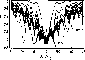
The characteristic of the train of impulses of cpmg sequence row also can change randomly.For example, can change the phase place of RF carrier pulse randomly to produce randomly such as 0 °, 90 °, 180 ° and 270 ° of impulse phases (in typical nuclear magnetic resonance (NMR) spectrometer, can produce this several phase places at least).(be depicted as and work as referring to accompanying drawing 18 (being depicted as the isoline 90 of the contrast signal loss of different number of echoes) and accompanying drawing 19 at ± 0.75 ω
1Space thickness on carry out the contrast signal loss of the different number of echoes of mean time isoline 92), shown in example in pulse produce randomly, and well logger 60 and 35 does not move.The randomization of pulse phase place, all the embodiment with mentioned above is identical with pulse parameter in all spins when this.
We can see that saturated the heating striate region many broads, that separate fully in the spin distributed areas.Littler by the width of zone of saturation than the width in the zone that produces by the cpmg sequence row that are subjected to moving influence, but saturated distribution plan is much more smooth than the distribution plan that is produced by the cpmg sequence row.This is illustrated in the scope (application coherence) of resonance zone and a kind of compromise proposal between the reliable saturated distribution (application random character) of measuring.Must be noted that for T
1,2(100ms here)<<t
mThe spin of (50ms here) (t here
mBe the cpmg sequence row duration), the distribution that the cpmg sequence row produce has more smooth shape.Producing to move in using random phase sequence process to increase its performance slightly, still keeps smooth but distribute.
Because be not that each hole all is to be heated with identical " speed ", so produce not exclusively saturated striate region.As our finding, depend on different position Δ ω, even some hole suppressed fully, as an example, per the 4th hole just be cannot see in accompanying drawing 20.These depend on duration of refocusing pulse in the position of fully saturated point: off resonance, a duration is t
pPulse make spin around pointing to
 " the effectively rotation axis " of direction rotates
Angle.The unsaturation point appears in the place that equals the multiple of 2 π at α.
Therefore, by changing ω
1T
p, can make these points saturated.
(be depicted as and work as at accompanying drawing 20 (being depicted as isoline 94) and accompanying drawing 21 at ± 0.75 ω for the contrast signal loss of different number of echoes
1The long-pending thickness of radial space on carry out the contrast signal loss of the different number of echoes of mean time isoline 96) in illustrate slow increase pulse length (in accompanying drawing 12 with " t
p" expression) and this effect of example.In this simulated experiment, pulse length is increased to 250 μ s (360 ° of pulses) in the 100th refocusing pulse linearly from the 125 μ s (180 ° of pulses) first time refocusing pulse, and t simultaneously
Ree(distance between the pulse is described at accompanying drawing 12) remains unchanged.All identical in other all parameters and the example in front.The saturated distribution of gained is more smooth and wideer slightly than the distribution that does not change the pulse length gained.
Once more, usually, for specific moving range can be by changing sequence various parameters so that the saturation effect optimization of pulse train, such as changing t
e(t
eApproximately with the inverse proportion that is partitioned into that is heated the hole), t
pWith impulse phase etc., and the compromise proposal between coherence and random character.
The example of the saturated sequence of front is used extremely, and off resonance hole heating effect produces saturated.As indicated above, the duration is t
pPulse always make the spin of off resonance rotate the angle [alpha] (Δ ω) bigger than normal flip angle α (0).Thereby for the refocusing pulse (that is, 180 degree pulses) with α (0)=180 °, it always keeps α (Δ ω)>180 ° for off resonance.On the other hand, if 180 ° of α (Δ ω)=(2n+1) then best excitation takes place, and would produce the Optimum Excitation off resonance thus.Then, spinning is θ=θ from effective flip angle of the longitudinal axis
Max, this moment, the effective flip angle for a given Δ ω maximum was
Thereby, use 180 ° of pulses and produce that off resonance is saturated may waste energy.
Accompanying drawing 22 and 23 has illustrated saturated distribution (averaging) and the relation that is applied in the α (0) of the refocusing pulse in the sequence on whole resonant space thickness.Change phase place as mentioned before randomly.In accompanying drawing 22, be depicted as Free Development time t
Ree(that is, in the time interval between refocusing pulse as shown in accompanying drawing 12) is set to contrast signal loss Figure 98 of 375 μ s, in accompanying drawing 23, is depicted as t
FreeBe set at contrast signal loss Figure 100 of 0.At the flip angle that shown in two accompanying drawings 22 and 23 all is Δ ω function is the loss of signal 98 and 100 of from 1 to 100 of the pulse of 9 °, 20 °, 30 °, 45 °, 90 ° and 180 °.By changing duration of pulse t
pProduce different flip angles.As our finding, for different time t
FreeThe loss of signal distributes much at one, thereby under the situation that random phase changes, saturation mode is mainly by the duration of pulse decision, rather than is determined by the Free Development duration.
The minimum pulse duration that can use for a given hardware, the rise-time constant by pulse (was called t
τ) decision.If t
p<3t
τ, then pulse does not reach maximal value ω before it ends
1, work as t
pWhen further reducing, its nearly unavailable that becomes very soon.Estimate it is t preferably for one in drill log NMR device
τ=5...30 μ s.
Work as t
pDuring minimizing, it is wideer that the zone of saturation becomes.In fact the zone of Guan Zhuing mainly meets
The zone, that is, and the zone of the α in two inner unsaturation points (Δ ω)<2 π.Flip angle θ along with the increase maximum of Δ ω
MaxReduce.Therefore, externally to produce saturated pulse many more in the zone for the wide more needs in zone of saturation.If saturated time constant is T
s, then have only T
1>T
sSpin can be saturated fully.Therefore, can realize a kind of in saturated bandwidth with still can realize saturated, minimum T
1Between compromise proposal.This also illustrates, in certain embodiments, and by with t
FreeBe reduced to the feasible hardware possible minimum that (the hardware problem here may comprise phase place switching time, pulse rising and fall time and make the RF circuit overloads with long continuous rf pulse), institute can realize, with the maintenance sequence as much as possible weak point be favourable.
Be respectively shown in the accompanying drawing 24 and 25 and have (accompanying drawing 24) and do not have (accompanying drawing 25) t
FreeThe loss 102 and 104 of sequence.Shown loss 102 with 104 at different relaxation times.For t
Free=375 μ s, the sequence of 100 refocusing pulses is that 40ms is long, if there is not the Free Development time, this sequence has only 2.4ms long.During for flip angle α (0)=35 ° of nominal, two sequences can both make the relaxation time of free fluid, and (spin of T1>50ms) is saturated, does not have the T of ratio but there is the sequence of Free Development time to make
1Low 20 times spin is saturated, and this needs for those people that want to solve the spin distribution problem of constrain fluids inside.In this two situation, producing saturated energy needed is single 180 ° of refocusing pulse energy needed
 Do not have serious problems this nuclear magnetic resonance for the down-hole (NMR) spectrometer, this nuclear magnetic resonance spectrometer usually can be at t
wHundreds of 180 ° of refocusing pulse strings have been produced during this time in the energy from be stored in capacitor.
Do not have serious problems this nuclear magnetic resonance for the down-hole (NMR) spectrometer, this nuclear magnetic resonance spectrometer usually can be at t
wHundreds of 180 ° of refocusing pulse strings have been produced during this time in the energy from be stored in capacitor.
In certain embodiments, more level and smooth a little by distribution than the distribution that the sequence by continuous radiation heats with the sequence heating that comprises the Free Development time.This may come from the additional phase error that Free Development produced in the time (not having in second kind of situation), but this is not conclusive.In addition, if tool axially the distance of the well logger dislocation of how much symmetric magnetic fields be
 From the position angle that is spun on its position, each spin all will be moved different displacements in the frequency space according to each
This just makes actual saturated distribution smooth more significantly.
In simulated experiment, use random generator and select four impulse phases.Therefore the sequence performance has a little variation in different simulated experiments.In certain embodiments, can use the sequence of a predetermined phase so that saturated best performance.In certain embodiments, the variation of optimal parameter is not periodic.
In a word, pretreated example technique for the spin in the adjacent domain of NMR resonance zone has been described above.Even the NMR device (such as, NMR well logger 60 or 35) between sample, moves, these technology all allow to measure based on polarized T 1, and these technology allow at least together with (application serial no is NO.09 as U.S. Patent application, 033,965, as above quote) described in the low gradient fields that has when carrying out drilling well astatically, carry out measurement together based on polarization.Well logger can be moved under the situation of stabilizator not having, so just make it become more " with the rig close friend ", greatly increase the usability of drilling well limit, limit record (LWD) well logger thus.
Though described the present invention by a limited number of embodiment,, under the help of the disclosed content of the application, can understand and make various modifications and variations thus for the person skilled in the art.
Claims (6)
1. a Nuclear Magnetic Resonance Measurement device that is used for wellhole relatively moves between the sample of this device and stratigraphic structure, comprising:
A) at least one magnet;
B) at least one coil; With
C) pulse producer that links to each other with described coil, this pulse producer is suitable for:
I) launch first rf pulse sequence by described coil;
Ii) change a parameter so that the first area of the sample of stratigraphic structure is saturated in the emission process of described first sequence, wherein said parameter is the phase place of the envelope or the radio-frequency carrier signal of described sequence;
Iii) launch second rf pulse sequence, in described first area, set up resonance zone by described coil; With
Iv) measure the characteristic of sample.
2. device as claimed in claim 1, wherein said parameter are envelopes, and described pulse producer changes described envelope.
3. device as claimed in claim 2, the step of wherein said change envelope further comprises the change pulse amplitude.
4. device as claimed in claim 2, the step of wherein said change envelope further comprise the interval that changes between the pulse.
5. device as claimed in claim 2, the step of wherein said change envelope further comprises the duration that changes pulse.
6. device as claimed in claim 1, wherein said parameter is the phase place of radio-frequency carrier signal, and the step that changes described parameter comprises and changes described phase place.
Applications Claiming Priority (2)
| Application Number | Priority Date | Filing Date | Title |
|---|---|---|---|
| US09/205965 | 1998-12-04 | ||
| US09/205,965 US6492809B1 (en) | 1998-12-04 | 1998-12-04 | Preconditioning spins near a nuclear magnetic resonance region |
Related Parent Applications (1)
| Application Number | Title | Priority Date | Filing Date |
|---|---|---|---|
| CN99124785A Division CN1256427A (en) | 1998-12-04 | 1999-12-06 | Pretreatment of spin near nuclear magnetic resonance area |
Publications (2)
| Publication Number | Publication Date |
|---|---|
| CN1560648A CN1560648A (en) | 2005-01-05 |
| CN100410681C true CN100410681C (en) | 2008-08-13 |
Family
ID=22764413
Family Applications (4)
| Application Number | Title | Priority Date | Filing Date |
|---|---|---|---|
| CN2008100058469A Expired - Fee Related CN101295012B (en) | 1998-12-04 | 1999-12-06 | NMR measuring device for borehole |
| CNB2004100699366A Expired - Fee Related CN100410681C (en) | 1998-12-04 | 1999-12-06 | Nuclear magnetic resonance pulse sequence for nuclear magnetic resonance device having relative moving with sample |
| CN99124785A Pending CN1256427A (en) | 1998-12-04 | 1999-12-06 | Pretreatment of spin near nuclear magnetic resonance area |
| CN2006101085479A Expired - Fee Related CN101074986B (en) | 1998-12-04 | 1999-12-06 | Method for NMR device for wellhole |
Family Applications Before (1)
| Application Number | Title | Priority Date | Filing Date |
|---|---|---|---|
| CN2008100058469A Expired - Fee Related CN101295012B (en) | 1998-12-04 | 1999-12-06 | NMR measuring device for borehole |
Family Applications After (2)
| Application Number | Title | Priority Date | Filing Date |
|---|---|---|---|
| CN99124785A Pending CN1256427A (en) | 1998-12-04 | 1999-12-06 | Pretreatment of spin near nuclear magnetic resonance area |
| CN2006101085479A Expired - Fee Related CN101074986B (en) | 1998-12-04 | 1999-12-06 | Method for NMR device for wellhole |
Country Status (12)
| Country | Link |
|---|---|
| US (2) | US6492809B1 (en) |
| CN (4) | CN101295012B (en) |
| AR (1) | AR021325A1 (en) |
| AU (1) | AU741353B2 (en) |
| CA (1) | CA2287141C (en) |
| DE (1) | DE19957767A1 (en) |
| EG (1) | EG22176A (en) |
| GB (1) | GB2346216B (en) |
| ID (1) | ID23962A (en) |
| MX (1) | MXPA03005196A (en) |
| NL (2) | NL1013602C2 (en) |
| NO (1) | NO331087B1 (en) |
Families Citing this family (45)
| Publication number | Priority date | Publication date | Assignee | Title |
|---|---|---|---|---|
| US6566874B1 (en) * | 1998-07-30 | 2003-05-20 | Schlumberger Technology Corporation | Detecting tool motion effects on nuclear magnetic resonance measurements |
| US6492809B1 (en) * | 1998-12-04 | 2002-12-10 | Schlumberger Technology Corporation | Preconditioning spins near a nuclear magnetic resonance region |
| US6891369B2 (en) * | 1998-08-13 | 2005-05-10 | Schlumberger Technology Corporation | Nuclear magnetic resonance method and logging apparatus for fluid analysis |
| GB2357149A (en) | 1999-12-08 | 2001-06-13 | Topspin Medical | MRI using non-homogeneous static field |
| US6704594B1 (en) | 2000-11-06 | 2004-03-09 | Topspin Medical (Israel) Limited | Magnetic resonance imaging device |
| US6528995B1 (en) * | 2001-09-10 | 2003-03-04 | Schlumberger Technology Corporation | Methods and apparatus for measuring flow velocity in a wellbore using NMR and applications using same |
| US6686737B2 (en) * | 2001-10-12 | 2004-02-03 | Baker Hughes Incorporated | Amplitude and/or phase modulated NMR pulse sequences |
| JP2003153903A (en) * | 2001-11-21 | 2003-05-27 | Toshiba Corp | Ultrasonograph and operating device thereof |
| US6774628B2 (en) * | 2002-01-18 | 2004-08-10 | Schlumberger Technology Corporation | Nuclear magnetic resonance imaging using phase encoding with non-linear gradient fields |
| US6984980B2 (en) * | 2002-02-14 | 2006-01-10 | Baker Hughes Incorporated | Method and apparatus for NMR sensor with loop-gap resonator |
| US6714009B2 (en) * | 2002-05-16 | 2004-03-30 | Schlumberger Technology Corporation | Method for the inversion of CPMG measurements enhanced by often repeated short wait time measurements |
| US6765380B2 (en) * | 2002-05-23 | 2004-07-20 | Schlumberger Technology Corporation | Determining wettability of an oil reservoir using borehole NMR measurements |
| US6937013B2 (en) * | 2002-06-19 | 2005-08-30 | Schlumberger Technology Corporation | NMR tool for making formation evaluation measurements using gradient echoes |
| US7015694B2 (en) * | 2002-08-19 | 2006-03-21 | Baker Hughes Incorporated | NMR apparatus and method for stochastic pulsing of earth formations |
| US6956370B2 (en) * | 2002-10-04 | 2005-10-18 | Schlumberger Technology Corporation | Method for reducing ringing in NMR measurements by combining NMR signals having a spin echo and spurious signal component |
| US6808028B2 (en) * | 2002-12-03 | 2004-10-26 | Schlumberger Technology Corporation | Method and apparatus utilizing NMR measurements to gather information on a property of the earth formation surrounding a wellbore |
| CN100375904C (en) * | 2002-12-24 | 2008-03-19 | 深圳安科高技术股份有限公司 | Radio frequency pulse angle phase setting method and circuit thereof |
| US6841996B2 (en) * | 2003-01-22 | 2005-01-11 | Schlumberger Technology Corporation | Nuclear magnetic resonance apparatus and methods for analyzing fluids extracted from earth formation |
| US7463027B2 (en) * | 2003-05-02 | 2008-12-09 | Halliburton Energy Services, Inc. | Systems and methods for deep-looking NMR logging |
| US6958604B2 (en) * | 2003-06-23 | 2005-10-25 | Schlumberger Technology Corporation | Apparatus and methods for J-edit nuclear magnetic resonance measurement |
| WO2005036208A2 (en) | 2003-10-03 | 2005-04-21 | Halliburton Energy Services, Inc. | System and methods for t1-based logging |
| US7268547B2 (en) * | 2003-10-07 | 2007-09-11 | Baker Hughes Incorporated | Correction of motion influences in NMR signals |
| US7382233B2 (en) * | 2004-05-08 | 2008-06-03 | Scott Steinetz | Sampling playback doorbell system |
| KR20060085382A (en) * | 2005-01-24 | 2006-07-27 | 주식회사 현대오토넷 | Apparatus utilizing static magnetic field of tire pressure monitoring system |
| US7787930B2 (en) * | 2005-04-25 | 2010-08-31 | The United States Of America As Represented By The Department Of Health And Human Services | Adiabatic T2 preparation sequence for magnetic resonance imaging with reduced B1 sensitivity |
| US7667462B2 (en) * | 2006-12-22 | 2010-02-23 | Schlumberger Technology Corporation | Nuclear magnetic resonance module |
| WO2009032731A2 (en) * | 2007-08-31 | 2009-03-12 | Baker Hughes Incorporated | Method and apparatus for nmr saturation |
| US8836329B2 (en) * | 2008-06-20 | 2014-09-16 | Weinberg Medical Physics Llc | Ultra-fast pre-polarizing magnetic resonance imaging method and system |
| US8324895B2 (en) * | 2009-01-23 | 2012-12-04 | Baker Hughes Incorporated | MWD/LWD NMR imaging with long echo trains |
| US8373412B2 (en) * | 2009-01-23 | 2013-02-12 | Baker Hughes Incorporated | NMR-LWD imaging tool |
| US10107930B2 (en) | 2012-05-16 | 2018-10-23 | Halliburton Energy Services, Inc. | Hybrid saturation recovery-inversion recovery pulse sequence for improved NMR logging of boreholes |
| CN103217586B (en) * | 2013-03-21 | 2015-04-08 | 中国科学院电工研究所 | Vector network analysis device based on nuclear magnetic resonance spectrometer |
| US9482631B2 (en) | 2013-05-14 | 2016-11-01 | Chevron U.S.A. Inc. | Formation core sample holder assembly and testing method for nuclear magnetic resonance measurements |
| CN105940185A (en) * | 2013-12-08 | 2016-09-14 | 普拉德研究及开发股份有限公司 | Downhole monitoring of fluids using nuclear magnetic resonance |
| SG11201608942PA (en) * | 2014-05-01 | 2016-11-29 | Halliburton Energy Services Inc | Casing segment having at least one transmission crossover arrangement |
| US9851315B2 (en) | 2014-12-11 | 2017-12-26 | Chevron U.S.A. Inc. | Methods for quantitative characterization of asphaltenes in solutions using two-dimensional low-field NMR measurement |
| CN108291440B (en) * | 2015-11-11 | 2022-03-29 | 斯伦贝谢技术有限公司 | Estimating nuclear magnetic resonance measurement quality |
| US10114142B2 (en) * | 2015-12-18 | 2018-10-30 | Schlumberger Technology Corporation | Imaging subterranean formations and features using multicoil NMR measurements |
| US10634746B2 (en) | 2016-03-29 | 2020-04-28 | Chevron U.S.A. Inc. | NMR measured pore fluid phase behavior measurements |
| EP3464819A4 (en) | 2016-08-08 | 2020-01-22 | Halliburton Energy Services, Inc. | Nuclear magnetic resonance sensing and fluid sampling device for subterranean characterization |
| EP3465185A4 (en) | 2016-08-08 | 2020-03-04 | Halliburton Energy Services, Inc. | Dual zone nuclear magnetic resonance sensing device for subterranean characterization |
| DE102017207631B4 (en) * | 2017-05-05 | 2019-06-06 | Siemens Healthcare Gmbh | Device and method for an asymmetrical bus interface of a local coil |
| CN107638179B (en) * | 2017-08-28 | 2020-09-04 | 上海联影医疗科技有限公司 | Method, system and computer readable storage medium for calculating magnetic resonance flip angle |
| US11899158B2 (en) * | 2022-03-14 | 2024-02-13 | Halliburton Energy Services, Inc. | Logging tool motion error reduction for nuclear magnetic resonance logging via pulse sub-sequences |
| US20230288600A1 (en) * | 2022-03-14 | 2023-09-14 | Halliburton Energy Services, Inc. | Logging tool motion error reduction for nuclear magnetic resonance logging via pulse angle selection |
Citations (4)
| Publication number | Priority date | Publication date | Assignee | Title |
|---|---|---|---|---|
| CN1064913A (en) * | 1990-12-05 | 1992-09-30 | 纽马公司 | The system that in drilling well, logs well |
| JPH08308810A (en) * | 1985-02-12 | 1996-11-26 | Max Planck Ges Foerderung Wissenschaft Ev | High-speed uptake method of spin resonance data and spin resonance device for local overhaul |
| US5705927A (en) * | 1992-07-30 | 1998-01-06 | Schlumberger Technology Corporation | Pulsed nuclear magnetism tool for formation evaluation while drilling including a shortened or truncated CPMG sequence |
| WO1998029639A1 (en) * | 1996-12-30 | 1998-07-09 | Numar Corporation | Method for formation evaluation while drilling |
Family Cites Families (33)
| Publication number | Priority date | Publication date | Assignee | Title |
|---|---|---|---|---|
| US4021726A (en) * | 1974-09-11 | 1977-05-03 | National Research Development Corporation | Image formation using nuclear magnetic resonance |
| US4350955A (en) | 1980-10-10 | 1982-09-21 | The United States Of America As Represented By The United States Department Of Energy | Magnetic resonance apparatus |
| US4389613A (en) * | 1981-04-15 | 1983-06-21 | Chevron Research Company | Computer-controlled, portable pulsed NMR instrument and method of use |
| US4585993A (en) * | 1983-12-14 | 1986-04-29 | General Electric Company | Method for selective NMR imaging of chemically-shifted nuclei |
| US4682106A (en) * | 1985-03-21 | 1987-07-21 | General Electric Company | Methods of, and apparatus for, proton decoupling in nuclear magnetic resonance spectroscopy |
| US5055787A (en) | 1986-08-27 | 1991-10-08 | Schlumberger Technology Corporation | Borehole measurement of NMR characteristics of earth formations |
| US4715383B1 (en) * | 1986-11-10 | 1995-10-31 | Mayo Medical Resources | Method for reducing artifacts in NMR images |
| US4986272A (en) * | 1989-08-09 | 1991-01-22 | Mayo Foundation For Medical Education And Research | NMR imaging with variable repetition |
| JP2957237B2 (en) * | 1990-06-22 | 1999-10-04 | 株式会社東芝 | Magnetic resonance imaging equipment |
| US5212447A (en) | 1990-12-03 | 1993-05-18 | Numar Corporation | Apparatus and technique for nmr diffusion measurement |
| US5245282A (en) * | 1991-06-28 | 1993-09-14 | University Of Virginia Alumni Patents Foundation | Three-dimensional magnetic resonance imaging |
| US5273040A (en) * | 1991-11-14 | 1993-12-28 | Picker International, Inc. | Measurement of vetricle volumes with cardiac MRI |
| US5629623A (en) | 1992-07-30 | 1997-05-13 | Schlumberger Technology Corporation | Pulsed nuclear magnetism tool for formation evaluation while drilling |
| EP0581666B1 (en) * | 1992-07-30 | 1997-10-01 | Schlumberger Limited | Pulsed nuclear magnetism tool for formation evaluation while drilling |
| AU7484694A (en) | 1993-08-13 | 1995-03-14 | Government Of The United States Of America, As Represented By The Secretary Of The Department Of Health And Human Services, The | Method for magnetic resonance spectroscopic imaging with multiple spin-echoes |
| AU711508B2 (en) | 1995-03-23 | 1999-10-14 | Schlumberger Technology B.V. | Nuclear magnetic resonance borehole logging apparatus and method |
| US6531868B2 (en) * | 1996-12-30 | 2003-03-11 | Halliburton Energy Services, Inc. | System and methods for formation evaluation while drilling |
| US6255817B1 (en) | 1997-06-23 | 2001-07-03 | Schlumberger Technology Corporation | Nuclear magnetic resonance logging with azimuthal resolution |
| DE19750214C2 (en) * | 1997-11-13 | 1999-12-30 | Univ Ludwigs Albert | Process for generating nuclear spin spectroscopic signals by spatial modulation of z-magnetization |
| US6237404B1 (en) | 1998-02-27 | 2001-05-29 | Schlumberger Technology Corporation | Apparatus and method for determining a drilling mode to optimize formation evaluation measurements |
| US6246236B1 (en) | 1998-03-03 | 2001-06-12 | Schlumberger Technology Corporation | Apparatus and method for obtaining a nuclear magnetic resonance measurement while drilling |
| US7501817B1 (en) | 1998-03-03 | 2009-03-10 | Schlumberger Technology Corporation | Method and apparatus for generating an axisymmetric magnetic field |
| US6291995B1 (en) | 1998-03-03 | 2001-09-18 | Schlumberger Technology Corporation | Apparatus and method for generating a pulse sequence |
| US6232778B1 (en) | 1998-06-11 | 2001-05-15 | Schlumberger Technology Corporation | Method for obtaining NMR bound fluid volume using partial polarization |
| US6326784B1 (en) | 1998-11-05 | 2001-12-04 | Schlumberger Technology Corporation | Nuclear magnetic resonance logging with azimuthal resolution using gradient coils |
| US6566874B1 (en) | 1998-07-30 | 2003-05-20 | Schlumberger Technology Corporation | Detecting tool motion effects on nuclear magnetic resonance measurements |
| US6492809B1 (en) * | 1998-12-04 | 2002-12-10 | Schlumberger Technology Corporation | Preconditioning spins near a nuclear magnetic resonance region |
| US6163153A (en) * | 1998-09-11 | 2000-12-19 | Western Atlas International, Inc. | Nuclear magnetic resonance pulse sequence for optimizing instrument electrical power usage |
| US6570381B1 (en) | 1999-03-25 | 2003-05-27 | Schlumberger Technology Corporation | Nuclear magnetic resonance well logging method and apparatus |
| US6297632B1 (en) | 1999-07-19 | 2001-10-02 | Schlumberger Technology Corporation | Detecting tool motion effects on spin echoes obtained with nuclear magnetic resonance measurements |
| US6400149B1 (en) | 2001-05-24 | 2002-06-04 | Schlumberger Technology Corporation | Nuclear magnetic resonance apparatus and method for generating an axisymmetric magnetic field having straight contour lines in the resonance region |
| US6528995B1 (en) | 2001-09-10 | 2003-03-04 | Schlumberger Technology Corporation | Methods and apparatus for measuring flow velocity in a wellbore using NMR and applications using same |
| US6518757B1 (en) | 2002-03-08 | 2003-02-11 | Schlumberger Technology Corporation | Use of CPMG sequences with phase cycled refocusing pulses in inside-out NMR for phase encoded imaging and to eliminate coherent ringing within one scan |
-
1998
- 1998-12-04 US US09/205,965 patent/US6492809B1/en not_active Expired - Lifetime
-
1999
- 1999-10-19 CA CA002287141A patent/CA2287141C/en not_active Expired - Fee Related
- 1999-11-02 GB GB9925826A patent/GB2346216B/en not_active Expired - Fee Related
- 1999-11-05 AU AU58313/99A patent/AU741353B2/en not_active Ceased
- 1999-11-18 AR ARP990105882A patent/AR021325A1/en active IP Right Grant
- 1999-11-18 NL NL1013602A patent/NL1013602C2/en not_active IP Right Cessation
- 1999-11-25 ID IDP991090D patent/ID23962A/en unknown
- 1999-12-01 EG EG153999A patent/EG22176A/en active
- 1999-12-01 DE DE19957767A patent/DE19957767A1/en not_active Withdrawn
- 1999-12-03 NO NO19995933A patent/NO331087B1/en not_active IP Right Cessation
- 1999-12-06 CN CN2008100058469A patent/CN101295012B/en not_active Expired - Fee Related
- 1999-12-06 CN CNB2004100699366A patent/CN100410681C/en not_active Expired - Fee Related
- 1999-12-06 CN CN99124785A patent/CN1256427A/en active Pending
- 1999-12-06 CN CN2006101085479A patent/CN101074986B/en not_active Expired - Fee Related
-
2002
- 2002-07-18 US US10/197,780 patent/US6844728B2/en not_active Expired - Lifetime
-
2003
- 2003-02-10 NL NL1022631A patent/NL1022631C2/en not_active IP Right Cessation
- 2003-06-11 MX MXPA03005196A patent/MXPA03005196A/en not_active IP Right Cessation
Patent Citations (5)
| Publication number | Priority date | Publication date | Assignee | Title |
|---|---|---|---|---|
| JPH08308810A (en) * | 1985-02-12 | 1996-11-26 | Max Planck Ges Foerderung Wissenschaft Ev | High-speed uptake method of spin resonance data and spin resonance device for local overhaul |
| CN1064913A (en) * | 1990-12-05 | 1992-09-30 | 纽马公司 | The system that in drilling well, logs well |
| US5280243A (en) * | 1990-12-05 | 1994-01-18 | Numar Corporation | System for logging a well during the drilling thereof |
| US5705927A (en) * | 1992-07-30 | 1998-01-06 | Schlumberger Technology Corporation | Pulsed nuclear magnetism tool for formation evaluation while drilling including a shortened or truncated CPMG sequence |
| WO1998029639A1 (en) * | 1996-12-30 | 1998-07-09 | Numar Corporation | Method for formation evaluation while drilling |
Also Published As
| Publication number | Publication date |
|---|---|
| AU5831399A (en) | 2000-07-20 |
| EG22176A (en) | 2002-10-31 |
| GB9925826D0 (en) | 1999-12-29 |
| NO995933D0 (en) | 1999-12-03 |
| US6492809B1 (en) | 2002-12-10 |
| NL1013602A1 (en) | 2000-06-06 |
| MXPA03005196A (en) | 2003-09-29 |
| AR021325A1 (en) | 2002-07-17 |
| CA2287141A1 (en) | 2000-06-04 |
| CN101295012B (en) | 2011-06-08 |
| AU741353B2 (en) | 2001-11-29 |
| CN101295012A (en) | 2008-10-29 |
| NL1013602C2 (en) | 2003-02-24 |
| NL1022631C2 (en) | 2007-02-13 |
| US6844728B2 (en) | 2005-01-18 |
| CN101074986B (en) | 2011-01-12 |
| NO995933L (en) | 2000-06-05 |
| DE19957767A1 (en) | 2000-06-08 |
| NL1022631A1 (en) | 2003-04-07 |
| US20030020473A1 (en) | 2003-01-30 |
| GB2346216B (en) | 2001-07-11 |
| CA2287141C (en) | 2004-08-31 |
| GB2346216A (en) | 2000-08-02 |
| CN1256427A (en) | 2000-06-14 |
| NO331087B1 (en) | 2011-10-03 |
| CN101074986A (en) | 2007-11-21 |
| CN1560648A (en) | 2005-01-05 |
| ID23962A (en) | 2000-06-08 |
Similar Documents
| Publication | Publication Date | Title |
|---|---|---|
| CN100410681C (en) | Nuclear magnetic resonance pulse sequence for nuclear magnetic resonance device having relative moving with sample | |
| CA2273126C (en) | Method for eliminating ringing during a nuclear magnetic resonance measurement | |
| US6366086B1 (en) | Apparatus and method for magnetic resonance logging | |
| US6459262B1 (en) | Toroidal receiver for NMR MWD | |
| CN101680936B (en) | Method and apparatus for high signal-to-noise ratio NMR well logging | |
| DE19952788B4 (en) | Apparatus and method for determining a nuclear magnetic resonance property | |
| AU711508B2 (en) | Nuclear magnetic resonance borehole logging apparatus and method | |
| US6522137B1 (en) | Two-dimensional magnetic resonance imaging in a borehole | |
| US6344744B2 (en) | Multiple frequency method for nuclear magnetic resonance longitudinal relaxation measurement and pulsing sequence for power use optimization | |
| CA2565587C (en) | Reduction of motion artifacts in nmr | |
| US6133734A (en) | Method and apparatus for evaluating an earth formation using nuclear magnetic resonance techiques | |
| US6586931B2 (en) | NMR logging in the earth's magnetic field | |
| CA2285791C (en) | Apparatus and method for generating a pulse sequence | |
| DE19952787A1 (en) | Method and device for determining a nuclear magnetic resonance property | |
| AU2004200905A1 (en) | Nuclear magnetic resonance measurements in well logging using an optimized rephasing pulse sequence | |
| WO2002095447A2 (en) | Nmr apparatus and method utilizing pulsed static magnetic fields | |
| US6498484B1 (en) | Method for reducing ringing in nuclear magnetic resonance well logging instruments | |
| US6518755B2 (en) | Measurement technique and apparatus for high-resolution multi-volume NMR well logging | |
| CN100409024C (en) | NMR spectrum analysis by means of gradient field NMR | |
| WO2006058005A1 (en) | Fast t1 measurement of an earth formation by using driven equilibrium | |
| MXPA99009936A (en) | Apparatus and method for calculating a spin-es relaxation time distribution | |
| AU2004200906A1 (en) | Nuclear magnetic resonance measurements in well logging using an optimized rephasing pulse sequence | |
| MXPA99010270A (en) | Pre-conditioning of espines near a region of magnetic resonance nucl |
Legal Events
| Date | Code | Title | Description |
|---|---|---|---|
| C06 | Publication | ||
| PB01 | Publication | ||
| C10 | Entry into substantive examination | ||
| SE01 | Entry into force of request for substantive examination | ||
| C14 | Grant of patent or utility model | ||
| GR01 | Patent grant | ||
| C17 | Cessation of patent right | ||
| CF01 | Termination of patent right due to non-payment of annual fee |
Granted publication date: 20080813 Termination date: 20131206 |