CN100437278C - Display - Google Patents
Display Download PDFInfo
- Publication number
- CN100437278C CN100437278C CNB2005100788114A CN200510078811A CN100437278C CN 100437278 C CN100437278 C CN 100437278C CN B2005100788114 A CNB2005100788114 A CN B2005100788114A CN 200510078811 A CN200510078811 A CN 200510078811A CN 100437278 C CN100437278 C CN 100437278C
- Authority
- CN
- China
- Prior art keywords
- display
- liquid crystal
- view
- liquid
- angular field
- Prior art date
- Legal status (The legal status is an assumption and is not a legal conclusion. Google has not performed a legal analysis and makes no representation as to the accuracy of the status listed.)
- Expired - Fee Related
Links
Images


Classifications
-
- G—PHYSICS
- G02—OPTICS
- G02F—OPTICAL DEVICES OR ARRANGEMENTS FOR THE CONTROL OF LIGHT BY MODIFICATION OF THE OPTICAL PROPERTIES OF THE MEDIA OF THE ELEMENTS INVOLVED THEREIN; NON-LINEAR OPTICS; FREQUENCY-CHANGING OF LIGHT; OPTICAL LOGIC ELEMENTS; OPTICAL ANALOGUE/DIGITAL CONVERTERS
- G02F1/00—Devices or arrangements for the control of the intensity, colour, phase, polarisation or direction of light arriving from an independent light source, e.g. switching, gating or modulating; Non-linear optics
- G02F1/01—Devices or arrangements for the control of the intensity, colour, phase, polarisation or direction of light arriving from an independent light source, e.g. switching, gating or modulating; Non-linear optics for the control of the intensity, phase, polarisation or colour
- G02F1/13—Devices or arrangements for the control of the intensity, colour, phase, polarisation or direction of light arriving from an independent light source, e.g. switching, gating or modulating; Non-linear optics for the control of the intensity, phase, polarisation or colour based on liquid crystals, e.g. single liquid crystal display cells
- G02F1/1323—Arrangements for providing a switchable viewing angle
-
- G—PHYSICS
- G02—OPTICS
- G02F—OPTICAL DEVICES OR ARRANGEMENTS FOR THE CONTROL OF LIGHT BY MODIFICATION OF THE OPTICAL PROPERTIES OF THE MEDIA OF THE ELEMENTS INVOLVED THEREIN; NON-LINEAR OPTICS; FREQUENCY-CHANGING OF LIGHT; OPTICAL LOGIC ELEMENTS; OPTICAL ANALOGUE/DIGITAL CONVERTERS
- G02F1/00—Devices or arrangements for the control of the intensity, colour, phase, polarisation or direction of light arriving from an independent light source, e.g. switching, gating or modulating; Non-linear optics
- G02F1/01—Devices or arrangements for the control of the intensity, colour, phase, polarisation or direction of light arriving from an independent light source, e.g. switching, gating or modulating; Non-linear optics for the control of the intensity, phase, polarisation or colour
- G02F1/13—Devices or arrangements for the control of the intensity, colour, phase, polarisation or direction of light arriving from an independent light source, e.g. switching, gating or modulating; Non-linear optics for the control of the intensity, phase, polarisation or colour based on liquid crystals, e.g. single liquid crystal display cells
- G02F1/133—Constructional arrangements; Operation of liquid crystal cells; Circuit arrangements
- G02F1/1333—Constructional arrangements; Manufacturing methods
- G02F1/1347—Arrangement of liquid crystal layers or cells in which the final condition of one light beam is achieved by the addition of the effects of two or more layers or cells
- G02F1/13471—Arrangement of liquid crystal layers or cells in which the final condition of one light beam is achieved by the addition of the effects of two or more layers or cells in which all the liquid crystal cells or layers remain transparent, e.g. FLC, ECB, DAP, HAN, TN, STN, SBE-LC cells
-
- G—PHYSICS
- G02—OPTICS
- G02F—OPTICAL DEVICES OR ARRANGEMENTS FOR THE CONTROL OF LIGHT BY MODIFICATION OF THE OPTICAL PROPERTIES OF THE MEDIA OF THE ELEMENTS INVOLVED THEREIN; NON-LINEAR OPTICS; FREQUENCY-CHANGING OF LIGHT; OPTICAL LOGIC ELEMENTS; OPTICAL ANALOGUE/DIGITAL CONVERTERS
- G02F1/00—Devices or arrangements for the control of the intensity, colour, phase, polarisation or direction of light arriving from an independent light source, e.g. switching, gating or modulating; Non-linear optics
- G02F1/01—Devices or arrangements for the control of the intensity, colour, phase, polarisation or direction of light arriving from an independent light source, e.g. switching, gating or modulating; Non-linear optics for the control of the intensity, phase, polarisation or colour
- G02F1/13—Devices or arrangements for the control of the intensity, colour, phase, polarisation or direction of light arriving from an independent light source, e.g. switching, gating or modulating; Non-linear optics for the control of the intensity, phase, polarisation or colour based on liquid crystals, e.g. single liquid crystal display cells
- G02F1/133—Constructional arrangements; Operation of liquid crystal cells; Circuit arrangements
- G02F1/1333—Constructional arrangements; Manufacturing methods
- G02F1/1335—Structural association of cells with optical devices, e.g. polarisers or reflectors
- G02F1/13363—Birefringent elements, e.g. for optical compensation
- G02F1/133634—Birefringent elements, e.g. for optical compensation the refractive index Nz perpendicular to the element surface being different from in-plane refractive indices Nx and Ny, e.g. biaxial or with normal optical axis
-
- G—PHYSICS
- G02—OPTICS
- G02F—OPTICAL DEVICES OR ARRANGEMENTS FOR THE CONTROL OF LIGHT BY MODIFICATION OF THE OPTICAL PROPERTIES OF THE MEDIA OF THE ELEMENTS INVOLVED THEREIN; NON-LINEAR OPTICS; FREQUENCY-CHANGING OF LIGHT; OPTICAL LOGIC ELEMENTS; OPTICAL ANALOGUE/DIGITAL CONVERTERS
- G02F1/00—Devices or arrangements for the control of the intensity, colour, phase, polarisation or direction of light arriving from an independent light source, e.g. switching, gating or modulating; Non-linear optics
- G02F1/01—Devices or arrangements for the control of the intensity, colour, phase, polarisation or direction of light arriving from an independent light source, e.g. switching, gating or modulating; Non-linear optics for the control of the intensity, phase, polarisation or colour
- G02F1/13—Devices or arrangements for the control of the intensity, colour, phase, polarisation or direction of light arriving from an independent light source, e.g. switching, gating or modulating; Non-linear optics for the control of the intensity, phase, polarisation or colour based on liquid crystals, e.g. single liquid crystal display cells
- G02F1/133—Constructional arrangements; Operation of liquid crystal cells; Circuit arrangements
- G02F1/1333—Constructional arrangements; Manufacturing methods
- G02F1/1337—Surface-induced orientation of the liquid crystal molecules, e.g. by alignment layers
- G02F1/133753—Surface-induced orientation of the liquid crystal molecules, e.g. by alignment layers with different alignment orientations or pretilt angles on a same surface, e.g. for grey scale or improved viewing angle
-
- G—PHYSICS
- G02—OPTICS
- G02F—OPTICAL DEVICES OR ARRANGEMENTS FOR THE CONTROL OF LIGHT BY MODIFICATION OF THE OPTICAL PROPERTIES OF THE MEDIA OF THE ELEMENTS INVOLVED THEREIN; NON-LINEAR OPTICS; FREQUENCY-CHANGING OF LIGHT; OPTICAL LOGIC ELEMENTS; OPTICAL ANALOGUE/DIGITAL CONVERTERS
- G02F1/00—Devices or arrangements for the control of the intensity, colour, phase, polarisation or direction of light arriving from an independent light source, e.g. switching, gating or modulating; Non-linear optics
- G02F1/01—Devices or arrangements for the control of the intensity, colour, phase, polarisation or direction of light arriving from an independent light source, e.g. switching, gating or modulating; Non-linear optics for the control of the intensity, phase, polarisation or colour
- G02F1/13—Devices or arrangements for the control of the intensity, colour, phase, polarisation or direction of light arriving from an independent light source, e.g. switching, gating or modulating; Non-linear optics for the control of the intensity, phase, polarisation or colour based on liquid crystals, e.g. single liquid crystal display cells
- G02F1/137—Devices or arrangements for the control of the intensity, colour, phase, polarisation or direction of light arriving from an independent light source, e.g. switching, gating or modulating; Non-linear optics for the control of the intensity, phase, polarisation or colour based on liquid crystals, e.g. single liquid crystal display cells characterised by the electro-optical or magneto-optical effect, e.g. field-induced phase transition, orientation effect, guest-host interaction or dynamic scattering
- G02F1/139—Devices or arrangements for the control of the intensity, colour, phase, polarisation or direction of light arriving from an independent light source, e.g. switching, gating or modulating; Non-linear optics for the control of the intensity, phase, polarisation or colour based on liquid crystals, e.g. single liquid crystal display cells characterised by the electro-optical or magneto-optical effect, e.g. field-induced phase transition, orientation effect, guest-host interaction or dynamic scattering based on orientation effects in which the liquid crystal remains transparent
- G02F1/1393—Devices or arrangements for the control of the intensity, colour, phase, polarisation or direction of light arriving from an independent light source, e.g. switching, gating or modulating; Non-linear optics for the control of the intensity, phase, polarisation or colour based on liquid crystals, e.g. single liquid crystal display cells characterised by the electro-optical or magneto-optical effect, e.g. field-induced phase transition, orientation effect, guest-host interaction or dynamic scattering based on orientation effects in which the liquid crystal remains transparent the birefringence of the liquid crystal being electrically controlled, e.g. ECB-, DAP-, HAN-, PI-LC cells
-
- G—PHYSICS
- G02—OPTICS
- G02F—OPTICAL DEVICES OR ARRANGEMENTS FOR THE CONTROL OF LIGHT BY MODIFICATION OF THE OPTICAL PROPERTIES OF THE MEDIA OF THE ELEMENTS INVOLVED THEREIN; NON-LINEAR OPTICS; FREQUENCY-CHANGING OF LIGHT; OPTICAL LOGIC ELEMENTS; OPTICAL ANALOGUE/DIGITAL CONVERTERS
- G02F2413/00—Indexing scheme related to G02F1/13363, i.e. to birefringent elements, e.g. for optical compensation, characterised by the number, position, orientation or value of the compensation plates
- G02F2413/02—Number of plates being 2
-
- G—PHYSICS
- G02—OPTICS
- G02F—OPTICAL DEVICES OR ARRANGEMENTS FOR THE CONTROL OF LIGHT BY MODIFICATION OF THE OPTICAL PROPERTIES OF THE MEDIA OF THE ELEMENTS INVOLVED THEREIN; NON-LINEAR OPTICS; FREQUENCY-CHANGING OF LIGHT; OPTICAL LOGIC ELEMENTS; OPTICAL ANALOGUE/DIGITAL CONVERTERS
- G02F2413/00—Indexing scheme related to G02F1/13363, i.e. to birefringent elements, e.g. for optical compensation, characterised by the number, position, orientation or value of the compensation plates
- G02F2413/07—All plates on one side of the LC cell
Abstract
A display is provided for switching between a narrow or private viewing mode and a wide or public viewing mode. The display comprises a display device which is controlled to provide display of a desired image or sequence of images. This is associated with a liquid crystal device having at least one liquid crystal layer whose molecules are switchable between a first state providing a first angular viewing range and a second state providing a second angular viewing range which is within and smaller than the first angular viewing range. With the molecules in the second state, the device at least partially blocks light propagating towards part of the first angular viewing range outside the second angular viewing range. The or each liquid crystal layer is in contact with at least one alignment surface, the or each of which comprises a uniform non-patterned alignment surface.
Description
Technical field
The present invention relates to a kind of display.
Background of invention
Electronic display unit for example is used for the monitor of computing machine and is built in the screen of phone and portable information apparatus, is usually designed to have wide as far as possible visual angle, so that they can be read from any observation place.Yet, in some cases, be useful only from the visible display of narrower angular field of view.For example, someone may wish to read a documentum privatum on crowded train.
The device of known multiple restriction angular field of view or position can be observed display from these angulars field of view or position.
US6552850 discloses a technology that is used for showing personal information on Automatic Teller Machine.The light that is sent by the machine display has fixing polarization state, and machine and user thereof are surrounded by the polaroid of a giant-screen, and polaroid absorbs the light of this polarization state, and the polarized light of transmission orthogonal state.The person of passing by can see user and machine, but can't see the information that shows on the screen.
Another known technology that is used to control light direction is " venetian blind type (louvred) " film.This film comprises to be similar to hyaline layer that replaces and the opaque layer that the Venetian blinds mode is arranged.As Venetian blinds, when light when the direction that almost is parallel to these layers is propagated, its allows light to pass, but absorbs those light of plane to propagate than wide-angle with respect to these layers.These layers can be other angle perpendicular to this film surface or with it.
The venetian blind type film can be cut into slices to the gained piece perpendicular to these layers and make then by piling up the many transparent and opaque materials that replace.This method is existing known for many years.For example, this method is disclosed US2053173, US2689387 and US3031351.
USRE27617 discloses a kind of technology, and wherein the venetian blind type film is cut out continuously from a cylindrical accumulation horizon blank.US4766023 has shown that how the optical quality of gained film and physical strength pass through the ultraviolet solidifiable monomer of coating, are exposed to ultraviolet radiation with film then and improve.US4764410 discloses a kind of similar technology, and wherein ultraviolet solidifiable material is used to the venetian blind type sheet is bonded to a cover film.
Also exist other method of making the film similar to this venetian blind type film performance.For example, US05147716 discloses a kind of light control film, and this film comprises the elongation particle that many edges direction vertical with thin film planar arranged.Those and this direction is light than wide-angle by strong absorption.
Another example of light control film is disclosed US05528319.In the embedding film transparent body is two layers or more multi-layered that are parallel to this thin film planar, and every layer has transparent and zone of opacity.Zone of opacity stops light along specific direction transmission film, and allows the transmission of light along other direction.
Above-mentioned film can be placed in before the display board, or places between transmittance display board and its back lighting device, to limit the angular range that display can be observed.In other words, they make display " privacyization ".Yet they all can not switch easily allowing and observe from the angular range of a broad.
US2002/0158967 illustrates light control film and how to be installed on the display, so that light control film moves in the display front, provides privacy mode, or mechanically shrinks in the support on display back or next door, and open mode is provided.Yet this method has following shortcoming: it comprises moving component, and this moving component may lose efficacy or damage, and had increased volume to display.
Another kind be used between open mode and privacy mode switching and the known technology that need not moving component be light control film is installed in display board after, and between light control film and display board, place a scatterer, this scatterer can electrically be connected and be cut off.When this scatterer is in inactive state, light control film restriction angular field of view, thus display is in privacy mode.When scatterer was switched on, it made light pass display board and propagate wider angle scope expert, thereby display is in open mode.Also light control film can be installed in before the display board, and switchable scatterer is placed before the light control film, to obtain effect same.This type of switchable privacy device is described in US5831698, among US6211930 and the US05877829.Their total shortcomings are no matter display is in open or privacy mode, and light control film always absorbs the light that incides greatly on it.Thereby this display is a poor efficiency in the utilization of light.Because under open mode, scatterer scatters light by the wider angle scope, thus these displays under open mode than more dim under privacy mode, unless backlightly opened brightlyer, to be compensated.
The third be used for providing switchable open/known method of privacy display is disclosed US5825436.Light controlling device in this patent is structurally similar to aforementioned venetian blind type film.Yet the opaque element of each in the venetian blind type film is substituted by a liquid crystal cells, and this liquid crystal cells can electrically be switched to pellucidity from opaque state.This light controlling device is placed in before or after the display board.When these unit when being opaque, display is in privacy mode; When these unit when being transparent, display is in open mode.
First shortcoming of this method is to make the difficulty and the cost of the liquid crystal cells with suitable shape.Second shortcoming is under privacy mode, and light may enter at a certain angle, makes to pass transparent material, a part of passing liquid crystal cells then earlier.Such light will can not absorbed by liquid crystal cells fully, thereby may reduce the privacy of this device.
JP2003-233074 and JP2003-28263 disclose a kind of LCD, and it provides the image of the routine of looking from the vertical angle of view to show.Yet, for departing from the relatively large visual angle of display normal, demonstrating a still image, this still image can be used to hide or " confusing " normal picture, thereby the privacy mode of operation is provided.This still image obtains by making the viewing area have mutually different orientation, although all pixels are with same pattern work.In this LCD, used a driving voltage that is lower than normal value.
A kind of device of even now can be used for providing privacy mode, but it is not changeable.Especially, when working as if the non-privacy of needs, the angular field of view of this relative narrower can not be changed, and wherein in whole this angular field of view, can see the on-fixed image.
Although US6445434 relate generally to a kind of in JP2003-233074 and JP2003-28263 disclosed single display board, not changeable privacy type of display, it discloses a kind of two display board displays that can switch really between open mode and privacy mode.The conventional LCD that is used for display image is set at after the liquid-crystal apparatus, and this liquid-crystal apparatus has the alignment layer of a patterning, and changeable, so that open mode and privacy mode to be provided.Under open mode, the visual angle almost not influence of this device to providing by display.Under privacy mode, the pattern that makes this alignment layer is being visible when departing from the view of display normal, so that one " obscuring " or " bluring " pattern to be provided, can't understand when being intended to make the image that demonstrates from these view.
Summary of the invention
According to a first aspect of the invention, a kind of display is provided, a controllable display device in order to provide image to show is provided this display, with first liquid-crystal apparatus with at least one liquid crystal layer, the molecule of this liquid crystal layer can and provide between second state of second angular field of view at first state that first angular field of view is provided and switch, second angular field of view is within first angular field of view and less than first angular field of view, first liquid-crystal apparatus is arranged to when liquid crystal molecule is in second state, stop at least in part towards the part of first angular field of view and the light of outside second angular field of view, propagating, this liquid crystal layer or each liquid crystal layer contact with at least one arrayed surface, it is characterized in that: this arrayed surface of this liquid crystal layer or each liquid crystal layer or each arrayed surface comprise the arrayed surface of a uniform non-patterning.
First liquid-crystal apparatus can comprise at least one linear polarizer.This liquid crystal layer or each liquid crystal layer can comprise nematic liquid crystal.This liquid crystal layer or each liquid crystal layer can be arranged to so that twisted nematic, twisted nematic, STN Super TN, homeotropic alignment are not come work to being listed as, reversing homeotropic alignment to one of row and compound arrangement nematic-mode.
This liquid crystal layer or each liquid crystal layer can be bistable.This liquid crystal layer or each liquid crystal layer can be bistable state twisted nematic or zenith bistable nematic (zenithal bistable nematic) layer.
First liquid-crystal apparatus can comprise a plurality of liquid crystal layers that are arranged to model identical work.This display can comprise and is arranged at the first and second twisted nematic liquid crystal layers between first and second linear polarizer, that have opposite torsional direction.This display can comprise and is arranged at the third and fourth twisted nematic liquid crystal layer between the second and the 3rd linear polarizer, that have opposite torsional direction.
This display can comprise first, second and the 3rd linear polarizer, and the first and second homeotropic alignment nematic liquid crystal layer, ground floor is disposed between first and second polarizers, second polarizer has a polarization direction perpendicular to the polarization direction of the first and the 3rd polarizer, and first and second states are respectively a pinwheel state and a basic no twisting states uniformly.
This at least one liquid crystal layer can comprise a homeotropic alignment nematic liquid crystal layer that is arranged between first and second polarizers and has a liquid crystal directors direction, when switching, its position angle is substantially parallel or perpendicular to the axis of homology of first and second polarizers.
This at least one liquid crystal layer can comprise a no twisted nematic layer that is arranged between first and second polarizers and has an orientation, and its position angle is arranged essentially parallel to the axis of homology of first and second polarizers.
This first liquid-crystal apparatus can comprise a fixing C plate delayer, this at least one liquid crystal layer can comprise a switchable C plate delayer, this switchable C plate delayer can switch between first state and second a different with it state, and the optical effect of this fixed delay device lost efficacy substantially under first state.This switchable C plate delayer can not have the optics effect substantially under second state.This fixed delay device can be a positive C plate delayer.This at least one liquid crystal layer can be a cholesteric liquid crystal layers.
This first liquid-crystal apparatus can be arranged to, and when liquid crystal molecule is in second state, stops the light that all are partly propagated towards first angular field of view basically.
First liquid-crystal apparatus can comprise at least one electrode, and this electrode or each electrode are uniformly, and are not patterned.
This first liquid-crystal apparatus can be arranged to, when liquid crystal molecule was in second state, on the light of partly propagating towards first angular field of view, the amplitude along spatial variations superposeed, constitute a fuzzy pattern, be used to make the image that demonstrates by display device to become basically and can not be understood.First liquid-crystal apparatus can comprise at least one electrode that carries out patterning with first pattern, this at least one electrode can be patterned, to determine first and second zones of this at least one liquid crystal layer, be used for when molecule is in second state, to spreading into the light of first angular field of view part, provide first and second decay respectively.These first and second times decay can be respectively minimum and maximum attenuation.This second area can be inactive, and can separate by a minimum insulation gap and this first area.
This first pattern can be a pattern of representing text.
This first pattern can be a gridiron pattern pattern.
This first pattern can be a pattern that constitutes an optical artifacts.
This first liquid-crystal apparatus can comprise an electrode again, and this electrode carries out patterning with second pattern that is different from first pattern.First and second patterns size that can take on a different character.
The electrode of this at least one patterning can comprise an addressable matrix, to allow the selection of fuzzy pattern.Display can comprise an electrod driving device, to produce a time dependent fuzzy pattern.
This electrode can be arranged to apply a voltage to this at least one liquid crystal layer, and this voltage changes from center to the edge of this at least one liquid crystal layer, thus the effect that departs from right-angle view at compensation edge.
When molecule is in second state, this first and second zone is for the angle in second angular field of view, the relation function that can have essentially identical " transmissivity (transmission)~with the angle of display normal ", and, then has different functions within first angular field of view and the angle outside second angular field of view.When molecule is in second state, determine that the electrode in first and second zones can be arranged to receive different voltage.Display can comprise a layer of compensation of cooperating with this at least one liquid crystal layer, so that identical functions to be provided.This layer of compensation can be arranged to, and is when molecule is in first state, disabled basically.This layer of compensation can comprise liquid crystal.
This at least one liquid crystal layer can comprise a surface modes layer, and this layer of compensation can comprise the surf zone of this surface modes layer.
According to a second aspect of the invention, a kind of display is provided, a controllable liquid-crystal apparatus in order to provide image to show is provided this display, with first liquid-crystal apparatus with at least one liquid crystal layer, the molecule of this liquid crystal layer can and provide between second state of second angular field of view at first state that first angular field of view is provided and switch, second angular field of view is within first angular field of view and less than first angular field of view, first liquid-crystal apparatus is arranged to when liquid crystal molecule is in second state, stop at least in part towards the part of first angular field of view and the light of outside second angular field of view, propagating, this at least one liquid crystal layer and at least one patterning, the arrayed surface that contains first and second zones contacts, this first and second zone has different orientations, it is characterized in that: this at least one liquid crystal layer comprises in Electronic Control birefringent elements and the homeotropic alignment nematic liquid crystal layer.
This orientation can be vertical mutually basically, and isogonism ground is spaced apart basically along azimuth direction around display normal for the part of first angular field of view.
First liquid-crystal apparatus can be removed from display device, and can append on the display device, to allow display in the operation of not having under the first liquid-crystal apparatus situation.
Second angular field of view can comprise display normal.
Second angular field of view can have a bisector that is not orthogonal to display.
Second angular field of view can comprise first and second subranges of arranging with different zenith angles with respect to display.
It is rotational symmetric that second angular field of view can be essentially.
Display can be arranged to, and when molecule is in second state, shows a sign.Display can be arranged to, and shows this sign in response to desiring the data presented content.
Display device can be radioparent.First liquid-crystal apparatus can be disposed in display device and backlight between.
Display device can be reflexive.
Display device can be semi-transparent reflection (transflective).
Display device can comprise one second liquid-crystal apparatus.
Display device can be luminous.Display device can be an organic light emitting apparatus.Display can comprise a circuit polarizer between display device and liquid-crystal apparatus.Display device can be arranged to send linearly polarized light.
First liquid-crystal apparatus can be arranged in before the display device.
Display can comprise an ambient light sensor, is used for when surround lighting is lower than a certain threshold value, makes display that second angular field of view is provided.
Display can comprise a vehicle display.
So just, may provide a kind of display, its visual angle can for example switched between a wide visual field mode and narrow (or privacy) visual field mode.First liquid-crystal apparatus can be used with a display device, and this display device can be any adequate types, and its operation need not to change with the Narrow Field Of Vision pattern in order to provide wide.
A display like this can be used to, for example, desk-top computer monitor, mobile phone, PDA(Personal Digital Assistant), mobile TV, mobile DVD (digital versatile disc) player/record mechanical, electrical sub-point of sale (EPOS) terminal and cash ATM (ATM (automatic teller machine)).A kind of like this device is simple, and can make by well-known and set manufacturing technology.In certain embodiments, first liquid-crystal apparatus for example, is determined pixel without any need for electrode patternization or inner structure.If first liquid-crystal apparatus has single liquid crystal region, be used for switching angular field of view across whole display device, then can use a very simple electrode pattern, and be easy to make.Although display can switch between first and second angulars field of view, the visual angle can change continuously or step by step by for example applying suitable driving voltage to first liquid-crystal apparatus.
This display can be used for one of needs and has " disclosing " wide visual angle, general pattern, and in the application of " privacy " pattern with narrow visual angle, so that for example, can read privacy information in public.
The Another Application of such display is in Vehicular instrument panel.For example, but the display viewing angles Be Controlled, so that passenger or driver can not see demonstration.Perhaps, the may command visual angle is to reduce the reflection of display on windshield and vehicle window, particularly under night or the dark situation of light.For automatic control is provided, for example, can be equipped with a luminance sensor and a backlight illumination controller.
In another one was used, first liquid-crystal apparatus served as a switchable compensation film.LCD is got up with the static compensation pellicular cascade usually, to improve viewing angle characteristic.This known structure is arranged to can provide best effect usually on a certain direction, is generally horizontal direction.For one rotatable and can be laterally or the display observed of vertical pattern, can switch compensation film so that provide the effect of improvement according to displaying contents, this will be favourable.
Such display also can be used on two or more images by spatially compound and be shown in the application scenario that device shows.For example, such display can have first pattern, and one of them image is shown across display, and second pattern, and wherein two or more different images are shown in the mode of space compound across display.Different patterns may need different optical compensations, can utilize a switchable compensator to reach this purpose.
The accompanying drawing summary
Fig. 1 a and 1b are the diagram that schematically explanation constitutes the display of the embodiment of the invention;
Fig. 2 a and 2b are the schematic cross section of display, and this display constitutes the embodiment of the invention, compares with conventional display, has single additional liquid crystal layer;
Fig. 3 a and 3b are the schematic cross section of display, and this display constitutes the embodiment of the invention, compares with conventional display, has two additional liquid crystal layer;
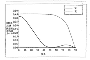
Fig. 3 c illustrates a schematic cross section, and a view of illustrating the location, position angle of one of Fig. 3 a display example;
Fig. 4 a and 4b are the light intensity map of illustrating the wide and narrow mode of operation of display shown in Fig. 3 c;
Fig. 5 a compares with conventional display for the schematic cross section of the display of formation one embodiment of the invention, has four additional liquid crystal layer;
Fig. 5 b shows the light intensity map of the work of Fig. 5 a display;
Fig. 6 a compares with conventional display for the schematic cross section of the display of formation one embodiment of the present of invention, has two additional liquid crystal layer;
Fig. 6 b illustrates the light intensity map of Fig. 6 a display;
Fig. 7 a and 7b have illustrated liquid crystal arrangement at the wide and Narrow Field Of Vision pattern of additional liquid crystal layer shown in Fig. 6 a;
Fig. 8 compares with conventional display for the schematic cross section of the display of formation one embodiment of the present of invention, has single additional liquid crystal layer and a static compensation thin layer;
Fig. 9 a to 9c has schematically illustrated the use of display, and this display has a two observing pattern, be used for providing two independently scenes to different observers, and the wide angle mould formula of single observation;
Figure 10 a and 10b are for constituting a synoptic diagram display, that be similar to Fig. 3 c of one embodiment of the invention;
Figure 11 a and 11b are the light intensity map of illustrating the wide and narrow mode of operation of Figure 10 a and 10b display;
Figure 12 a and 12b are for constituting a synoptic diagram display, that be similar to Fig. 3 c of another embodiment of the present invention;
Figure 13 a and 13b are the light intensity map of illustrating the wide and narrow mode of operation of Figure 12 a and 12b display;
Figure 14 to 16 has illustrated the example of electrode patternization;
Figure 17 has illustrated an arrangement of electrodes and drive scheme at a display;
Figure 18 has illustrated the effect of the off-normal observation at display edge;
Figure 19 a has illustrated a patterning of the liquid crystal layer of patterned arrangement;
Figure 19 b shows at the light intensity map with the zones of different of arranging shown in Figure 19 a;
Figure 20 is the schematic cross section of the display of formation one embodiment of the invention;
Figure 21 a and 21b illustrate display desirable and the transmissivity of actual transmissison characteristic and the view of angular relationship;
Figure 22 has illustrated another arrangement of electrodes and drive scheme;
Figure 23 to 28 is for illustrating the schematic cross section of the display that constitutes the more embodiment of the present invention;
Figure 29 schematically shows the viewing angle characteristic of display shown in Figure 28;
Figure 30 a and 30b are the diagram of illustrating the display that constitutes another embodiment of the present invention; And,
Figure 31 a and 31b are the light intensity map of illustrating Figure 30 a and the work of 30b display;
In whole accompanying drawings, similar reference number refers to similar part.
Embodiment
Fig. 1 a shows a display that comprises transmission display unit 1, and this transmittance display device can be the display device of traditional type, and need not to do any variation for the demonstration with the wide visual field and Narrow Field Of Vision pattern is provided.For example, display device 1 can be thin film transistor (TFT) (TFT) liquid crystal board, and it provides the panchromatic or monochromatic demonstration of pixelation in response to the view data of supplying with display.
Display also comprise one backlight 2, it sends in the whole relative wider angle distribution range shown in 3 has the inhomogeneity light of rational strength.The traditional type that backlight 2 also can be in the known display is adopted backlight.
Display comprises one or more being arranged in from backlight 2 optional features 4 to the light path of display device 1.This optional feature or each optional feature comprise a liquid-crystal apparatus, and this liquid-crystal apparatus has one or more liquid crystal layers and one or more polarizer.These parts or each parts 4 for example between the narrow observing pattern and wide observing pattern shown in 5 and 6, according to the electric field that is applied on this liquid crystal layer or each liquid crystal layer, provide angular light to regulate.The electric field that is applied can switch between two values, to provide two angular distribution, perhaps serially or with discrete change of stride, to provide the angle range of observation more than two.
In the device shown in Fig. 1 a, 4 pairs of angular light distribution 3 from backlight 2 of additional one or more parts almost do not influence, shown in 7.Yet, when display is worked with narrow mode, these parts or each parts 4 Be Controlled are so that be limited in angular light distribution in the close limit shown in 8, so that user 9 only can watch image or the image sequence that is shown by display device 1 in the angle range of observation of relative narrower.This can be used to, and for example, watches for unique user 9 provides privacy, and avoids outside this narrower angle range of observation other people to see the image of demonstration.When display is in wide visual field mode, be positioned at relative broad angular field of view optional position for example 9 usefulness can see the image of demonstration per family.
Fig. 1 b shows a display, and the display difference is that this optional feature or each optional feature 4 are positioned at before the display device 1 shown in itself and Fig. 1 a.Thereby this display device 1 is not limited to the transmission-type shown in Fig. 1 a, but can be any type, for example transmission-type, reflection-type or emission type.Display device 1 provides the angular light distribution of relative broad, shown in 3, and this optional feature or each optional feature 4 adjusting angle light distribution between wide mode and narrow mode, shown in 7 and 8.
Fig. 2 a and 2b illustrate the thin film transistor plate 1 of liquid crystal type when saturating, the example of display shown in Fig. 1 a and the 1b respectively.Two displays thus all have backlight 2, and except the order that each device of display interior is provided with, can be basic identical.LCD (LCD) plate 1 comprises the liquid crystal layer 10 that is arranged between input and output polarizer 11 and 12.For the purpose of clear, other parts have been omitted, as substrate, alignment layer, electrode assembly and filtering apparatus.
In the display of Fig. 2 a, optional feature 4 is disposed between LCD plate 1 and backlight 2, so that additional liquid crystal (LC) layer 15 is cooperated with polarizer 11 and 16.In the display of Fig. 2 b, optional feature 4 is disposed in LCD plate and 2 (forming a TFT module 1,2) backlight before, so that additional LC layer 15 is cooperated with polarizer 12 and 16.
Fig. 3 a and 3b show respectively and are different from the display shown in Fig. 2 a and the 2b, and its difference is that optional feature 4 comprises second liquid crystal layer 18, and this layer 18 is provided with evenly not the alignment layer 18b and the 18c of patterning, are formed on evenly not on patterned electrodes 18a and the 18d.Fig. 3 c shows an instantiation of display shown in Fig. 3 a, and wherein, polarizer 11 and 16 has the parallel axis of homology, and a benchmark or 0 ° of direction have been determined in this azimuth orientation.In the layer 15 and 18 each comprises one 90 ° twisted nematics (TN) liquid crystal layer.For to be 0 °, and be 90 ° about reference direction in the orientation at layer 15 upper surface place and guides azimuth orientation in the guides azimuth orientation at layer 15 lower surface place about reference direction.For layer 18, upper and lower guides azimuth orientation is respectively about reference direction and is 90 ° and 0 °.Under wide mode, do not apply voltage across layer 15 and 18, and under narrow mode, apply one two volts electric field across in layer 15 and 18 each.
Fig. 4 a illustrates for wide and narrow mode, 360 ° of azimuth coverages and 90 ° of light intensity maps that the polar angle scope is interior.Under narrow mode, TN liquid crystal layer 15 and 18 is cooperated with polarizer 11 and 16, with light intensity and angle limitations in surface level.This is illustrated among Fig. 4 b, and Fig. 4 b has shown that light intensity is with the variation of polar angle at place, 90 ° of position angles, and 0 ° is the normal direction of display surface here.
As previously mentioned, voltage continuous or discrete range can be applied on the layer 15 and 18.And the voltage that is applied on the layer 15 and 18 needn't be identical.And, although only show an additional polariser 16,, may need or expect to contain more additional polariser according to layer 15 and 18 liquid crystal mode, for example be arranged between layers 15 and 18.
It is the visual angle that obtains a relative narrower in 90 ° the plane that display shown in Fig. 3 c allows having the position angle.For a narrower visual angle perpendicular to this plane is provided, also a display shown in Fig. 5 a can be set.
The difference of the display shown in the display shown in Fig. 5 a and Fig. 3 c is to be provided with another to liquid crystal layer 19 and 20, and another linear polarizer 21, and display is Fig. 3 b shown type, wherein plate 1 backlight 2 and optional feature 4 between. Liquid crystal layer 19 and 20 and the orientation of the linear polarizer 21 that adds and liquid crystal layer 15 and 18 and the oriented phase of polarizer 16 with, but two overlap the surperficial pre-tilt angle difference between the liquid crystal layers.Different surperficial pre-tilt angle causes opposite reversing between two cover liquid crystal layers.Liquid crystal layer has evenly the not alignment layer and the electrode 19a-19d of patterning, 20a-20d.
Fig. 5 b has represented only to have layer 15 and 18 at 25 and 26 places, or layer 19 and 20 o'clock, the light intensity map under narrow observing pattern are only arranged.The narrow observing pattern of whole display is shown in 27 places, and the wide observing pattern of whole display is shown in 28 places.
Display shown in Fig. 6 a is similar to Fig. 3 c shown type, works under row (VAN) pattern in homeotropic alignment but difference is layer 15 and 18, and is separated by another polarizer 30.The polarizer 11 and 16 the axis of homology are parallel to each other, and perpendicular to the axis of homology of polarizer 30.
In the case, liquid crystal layer 15 and 18 is disposed between electrode 15a, 15d, 18a, the 18d, and one of this electrode can be the plane, and remaining electrode is patterned, and switches between suitable liquid crystal directors configuration can make each liquid crystal layer.Under no any situation that applies electric field, each layer is homeotropic alignment, as among Fig. 7 a and the 7b shown in 31 and 32.Under the wide field-of-view mode shown in Fig. 7 a, on each liquid crystal layer 15 and 18, apply an electric field, arrange (CPA, continuous pinwheelalignment) to produce a continuous pinwheel, shown in 33.This is to obtain by applying an electric field that is substantially perpendicular to substrate, and wherein this substrate has the cell surface of suitable electrode structure and nonuniform plane degree.This mode of operation provides the angular distribution of a non-constant width, has so just provided a good wide angle mould formula.
Under narrow mode, utilize this electrode structure to apply an electric field, to introduce a plane electric fields and one perpendicular to the electric field of cell surface, shown in 35.Under this pattern, liquid crystal molecule is arranged along the equidirectional that is located substantially in the plane, shown in 36.By arranging layer 15 and 18, make the orientation in this pattern lower plane orthogonal, can obtain a good narrow mode of operation, shown in the light intensity map of Fig. 6 b.
An example of embodiment described in Fig. 8 relates to static compensation film 60, and it is the cholesteric liquid crystal layers of a short pitch, serves as a static quadrature reactance c-plate delayer.The pitch of liquid crystal layer 15,18 is less than the light wavelength of passing it, and, when not switching, serve as a negative c-plate delayer.When switching with an electric field, this reverses " being untied (unbound) ", liquid crystal layer 15,18 homeotropic alignments, and serve as a positive c-plate delayer.When the liquid crystal layer 15,18 that is in switching state not and static compensation film 60 were combined, switching state was not provided a wide visual field mode of operation by full remuneration.On the contrary, when the liquid crystal layer 15,18 that is in switching state and static compensation film 60 were combined, the delay of two layers was applied, and provides a Narrow Field Of Vision mode of operation.
Previous embodiment can be used as a switchable viewing angle compensator that is used for accessible many visuals field display, and this display is for example disclosed type in GB2405516.Do not use many visuals field display of parallax optics the asymmetric visual angle characteristic of liquid crystal mode can be used in combination with suitable drive scheme.For example, Fig. 9 a shows the wild display of a double vision, and it comprises a dissymmetric mode LC plate 40, and the pixel of this plate 40 is assigned to first and second groups.First group pixel, for example pixel 1, come addressing by first drive scheme, and this first drive scheme produces an image that is used for observation in first field of view 41, and first group pixel presents black in second field of view 42.On the contrary, second group pixel, for example pixel 2, come addressing or driving by second drive scheme, so that an image is visible in field of view 42, and when from field of view 41 observations, second group pixel presents black.
Such display can be by utilizing the 3rd drive scheme addressing or drive all pixels, and be switched to the wild wide field-of-view mode of haplopia.Its effect is shown in Fig. 9 b, and wherein the 3rd drive scheme produces a non-constant width but asymmetric visual angle (comprising display normal).Yet the asymmetry at visual angle may not expected in this pattern.
Fig. 9 c shows a kind of device, and wherein the asymmetry at wide visual angle is reduced or is eliminated basically.Especially, a device 43 that is arranged in before the plate 40 and comprises the interpolation of one or more liquid crystal compensation layers provides viewing angle compensation.When display was in double vision angle mould formula, device 43 can be switched so that or to field of view 41 and 42 essentially no influences, or provide some improvement to these two kinds of observing effects.
In some cases, those use the display of switchable parallax optical system in order to switch between single-view and various visual angles pattern, also can be advantageously the viewing angle characteristic of asymmetric liquid crystal mode be used in combination with a suitable drive scheme, to improve the separation of images of under the various visual angles pattern, carrying out by the parallax optics.When display was switched to the work of haplopia angular width visual angle, having an asymmetric viewing angle characteristic may not expect again.Thereby, also can use a device 43 that comprises one or more liquid crystal layers, improving the viewing angle characteristic of display under wide field-of-view mode, and the various visual angles effect under the various visual angles pattern do not influenced or make moderate progress.
Figure 10 a and 10b show a kind of display, and the difference of display shown in itself and Fig. 2 a is that liquid crystal layer 15 comprises the liquid crystal that is arranged in parallel that forms electrically conerolled birefringence (ECB) device.Polarizer 11 and 16 polarization transmission direction are parallel to each other, and are parallel to the orientation of liquid crystal layer 15, shown in Figure 10 b.When not having across liquid crystal layer 15 when applying voltage, the essentially no influence of liquid crystal layer, and the transmissison characteristic of optional feature 4 transmissison characteristic with two parallel polarizer is identical basically, shown in " wide mode " among Figure 11 a.When applying a small voltage across liquid crystal layer 15, just obtained narrow mode, the viewing angle characteristic of this narrow mode is shown in the right-hand side among Figure 11 a.Figure 11 b illustrates for 90 ° of directions shown in Figure 11 a, the curve of brightness and angular relationship.
The ECB device can also be formed between two substrates, and these two substrates have transparent indium tin oxide (ITO) electrode.This electrode is coated with polyimide alignment layer SE610, and it can obtain from Nissan Chemical.This alignment layer is rubbed so that an orientation to be provided, and assembles this substrate then, so that orientation is non-parallel.This substrate is spaced apart with 8 microns with the glass partition pearl, and resulting unit is filled full with the liquid crystal of ZLI4619-100 type.Resulting device is installed to, for example a front of being furnished with conventional transmission type lcd device backlight.The frictional direction of alignment layer is parallel to the transmission direction of the polarizer of image display front.Another polarizer is laminated to the front of ECB device, and the polarization direction of this ECB device is parallel to the frictional direction of alignment layer.Do not having voltage to be applied under the situation of liquid crystal layer of ECB device, display has basic wide visual angle of not reducing.When across the ECB device liquid crystal layer when applying about 2.3 volts small voltage, display is becoming with the orientation of the alignment layer of ECB device on 90 ° the azimuth direction lower substantially transmission is provided.
Figure 12 a and 12b show a kind of display, and the difference of display is that liquid crystal layer 15 is nematic phase (VAN) types of homeotropic alignment shown in itself and Figure 10 a and the 10b.In addition, polarizer 11 is parallel with 16 transmission direction, and also is parallel to liquid crystal directors when liquid crystal layer 15 switches.Moreover when not applying voltage across liquid crystal layer 15, layer 15 essentially no influence can obtain the illustrated wide field-of-view mode of Figure 13 a left part.When applying small voltage, can obtain the illustrated narrow mode transmissison characteristic of Figure 13 a right side part and Figure 13 b across liquid crystal layer 15.The illustrated narrow mode performance of Figure 13 a and 13b be for the transmission direction of polarizer 11 and 16 with the direction at 45 of 0 ° of position angle shown in Figure 13 a on situation.
In a kind of like this specific embodiment of device, for example be coated with the polyimide alignment layer that the substrate of ITO comprises JALS20017 on coated, JALS20017 can obtain from JSR Chemical.This alignment layer is rubbed with the orientation that provides to become very little inclination with alignment layer vertical line or normal.Assemble this substrate and this substrate is spaced apart so that 9 microns cell gap to be provided with nonparallel orientation with the glass partition pearl.This unit has been full of the liquid crystal of MLC-6610 type, and resulting device is attached the front at display, for example in the front of being furnished with Sharp ASV escope backlight.The frictional direction of alignment layer is parallel to the polarization transmission direction of the polarizer of image LCD front, and this direction is from the horizontal by 45 °.
Another polarizer is layered in the front of device, and the polarization transmission direction of this device is parallel to the frictional direction of alignment layer.When there not being voltage to be applied to layer 15 the time, the viewing angle properties that the VAN device shows image produces and seldom influences or do not have an influence.When applying 10 volts voltage across liquid crystal layer 15, the VAN device with the orientation of layer 15 azimuthal direction at 45 on lower substantially transmission is provided.
Any embodiment of Miao Shuing can be arranged to herein, when display is in privacy or narrow field-of-view mode, can offer a kind of indication of user.For example, this can provide in software, and this software produces an image that is shown or sign represents that this display is in privacy mode.A sign like this can cover, and for example on the display image of the bottom of screen, perhaps can comprise speech " privacy ".As selection, this function can also be arranged in the image display or in the optional feature, when display switched to privacy mode, the demonstration of the parts of images of optional feature was worked to show suitable sign like this.
Herein the display of Miao Shuing can with a kind of device or configuration combination be provided in a kind of device or configuration on, this device or to be configured in the picture material that is shown be when suiting type display to be automatically switched to privacy mode.For example, if display is used for display web page, then relevant with webpage any software mark all can be used to trigger scope, makes it be operated in privacy mode.An example of this application is, when browser is operated under the secret encryption mode, for example when checking that Private Banking's detail is maybe when carrying out secure transactions.
When display is the part of data input device or is associated with data input device, and the input data type that maybe will be transfused to also may automatically make display switch to privacy mode when needing the privacy display mode.For example, the input of PIN (PIN) can make display be transformed into privacy mode automatically.Such configuration is passable, for example uses with " chip and pin (chip and pin) " technology in the retail transaction exit.
In many embodiments described herein, optional feature provides privacy or narrow field-of-view mode effectively by stopping the light that enters into the wide field of view part of narrow field of view outside through image display 1 substantially.But during narrow field-of-view mode, also only stop portions for example makes and see obscuring or fuzzy pattern of stack on the image that display shows at the light of narrow field of view outside.In most of embodiment described herein, the liquid crystal arrangement layer of optional feature 4 is non-patternings or uniform, so that whole liquid crystal layer 15 all is in uniform state under narrow and wide two kinds of field-of-view modes, but its state is different under two kinds of patterns.When display provides narrow by the light that stops outside, narrow visual angle fully or during privacy mode, the electrode that links with layer 15 also can be non-patterning.But, obscure or during fuzzy pattern, the electrode of one or more patternings also can link with liquid crystal layer 15 when providing for the intelligibility with display image is restricted to narrow angular field of view.
For example, Figure 14 shows the patterning of electrode 15a, so that fixing gridiron pattern or checkerboard pattern to be provided.Like this, in narrow field-of-view mode, comprise the part of single public electrode shown in Figure 14 for the zone of black, it is used for applying voltage across liquid crystal layer 15, and the zone that is depicted as white comprises gap in the electrode, does not therefore have the voltage that applies across liquid crystal layer 15.Thereby the pattern that also may provide a narrow angular field of view outside to see, the image that its more effectively fuzzy display shows is to strengthen confidentiality.
The patterning of electrode 15a and the resulting pattern of obscuring or bluring can be any suitable types.Another kind as the gridiron pattern pattern shown in Figure 14 is selected, and the image that causes optical illusion can be provided, and Figure 15 shows a such example.Such optical illusion produces the confidentiality that image can further strengthen narrow field-of-view mode.As another selection, blurred picture can comprise text, and Figure 16 shows such example of explanation exabyte or logo use.Available suitable text came patterning during electrode 15a made, and the electrode pattern structure of selecting from optional several different texts or other images also may be provided.
Can select this fuzzy pattern fully to blur the image that is shown, so that it is unintelligible in narrow angular field of view outside.In order to realize this purpose, fuzzy image can comprise the feature of the size suitable with the characteristic dimension of the image that shows.For example, comprise the display image of text, for example in mail, can blur by the blurred picture in the pattern form with the character same size in basic and the text.
For fuzzy different images, can provide the fuzzy pattern of difference of different characteristic size with different characteristic size.For example, electrode on liquid crystal layer 15 opposite sides for example such as 15a and 15b can come patterning with the different characteristic size.Each electrode is patterned to form two group zones at least, and the voltage that applies on these zones can be controlled independent of one another.External series gap between adjacent area belongs to different groups, and this external series gap can make enough little, and like this, when identical voltage was applied on the zone of all groups, the electrode role of patterning and uniform non-patterned electrodes were basic identical.
When not on the same group the zone of electrode 15a receives different voltages, and not on the same group the zone of electrode 15d is when receiving identical voltage, and what the patterning of electrode 15a was seen is the image that blurs.On the contrary, when not on the same group the zone of electrode 15a receives identical voltage, and not on the same group the zone of electrode 15d is when receiving different voltage, and what the patterning of electrode 15d was seen is the image that blurs.
Such layout is used between two kinds of different sizes of gridiron pattern pattern of fuzzy two kinds of kinds of characters sizes and selects.Even this display is observed from different substantially distances, also can use such layout.Switching between these patterns can be finished automatically according to the content of the data that are provided to display, for example according to main font size.Such layout also is used between two kinds of different logos on the electrode or " patterning " information and selects.For example, the user can select to use the information and the unhandsome information of courtesy.
In another embodiment, be used for to adopt the form of active or passive address matrix across the electrode that liquid crystal layer or multilayer apply voltage.For example, addressing can be undertaken by known " duty method (duty method) ".This matrix addressing makes provides suitable image address data by the electrode of giving optional feature 4, produces any required fuzzy pattern.Therefore, blurred picture can change constantly and maybe can change or upgrade so that the image of variation to be provided in embodiments, and wherein the liquid crystal mode of optional feature 4 allows rapid image to upgrade in these embodiments, for example under normal video speed.Equally, such matrix addressing as indicated above arrange make blurred picture have different can selecteed characteristic dimension.
In the situation of this time dependent pattern of needs or image, thereby its visibility that also can change blurred picture by the voltage that change is applied to the fixed electorde pattern realizes.Voltage can be applied on the different electrode zones progressively, so that the form of blurred picture changes in time.Under the situation of matrix-addressable type device, can show the time dependent arbitrarily image of obscuring, and when this image display showed " figure " image with the paired ratio of text, it can provide the confidentiality of enhancing.This time dependent image also can be the type that causes optical illusion.
Under the situation of patterned electrodes, because the optical loss of electrode layer material, this pattern may be in sight under the open or wide field-of-view mode of display.Yet, provide electrical isolation by separating very narrow gap between the patterned electrode layer that makes two or more continuous electrode zones, can avoid above-mentioned situation substantially.For example, can there be 10 micron-sized width in this gap.Therefore, the whole visible area of display is covered by electrode layer basically, and this electrode layer is enough evenly to avoid under wide field-of-view mode this pattern in sight.Under narrow field-of-view mode, voltage is applied to the electrode zone of selection and other zones are made as no-voltage.Figure 17 shows an example of the suitable pattern of electrode layer 15a.
As selecting or other, during the wide field-of-view mode of patterned electrode layer,, can eliminate visibility substantially by using the insulation course covers electrode layer to the similar refractive index of electrode material.Thus, can become even substantially across the optical loss on the visible surface of display.
In some cases, when privacy mode, for the observer of an observation display in the narrow field of view, that these are obscured or fuzzy pattern might be visible.For example, as shown in figure 18, observer 45 may be in certain position before the display board 40, so that the view angle theta in display edge or corner is obscured image and become visible even as big as making.This effect can be passed through, for example, at the edge of optional feature 4 liquid crystal layers and/or the corner apply one or several different voltages and avoid.Like this, the privacy class that is provided by the edge and/or the corner of optional feature can so that under the narrow mode or privacy mode of display, for an observer who is in the tram, be reduced the observability of obscuring pattern by independent adjustment.
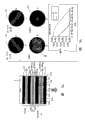
In aforementioned a plurality of embodiment, at least one liquid crystal layer is limited to only axle with the visual angle of display in the optional feature 4.These embodiment have the advantage that need not the alignment layer patterning.Yet by the alignment layer of patterning is provided, single liquid crystal layer just may be under privacy mode, with angle limitations at two basically on the axle of quadrature.This arrangement is shown among Figure 19 a, and wherein, the alignment layer zone with perpendicular array direction is arranged to gridiron pattern (Chequerboard) pattern.Like this, for example 46 first area is shown as in Figure 19 a and has vertical, antiparallel arrangement, and for example 47 second area is shown as the antiparallel arrangement with level.
This display can provide as optional feature 4 by forming an ECB device.Two ito substrates can the coated polyimide alignment layer SE610 that goes up from Nissan Chemical, and rubs, so that the first order direction to be provided.Then, each alignment layer can coated last layer Shipley 1805 photoresists.Photoresist is carried out patterning with conventional photoetching process, is stayed being covered with photoresist and the alignment layer zone that alternates that exposed.The alignment layer of part exposure is rubbed once more, so that the second order direction to be provided, removes photoresist then.Then, assembling substrates is to provide antiparallel arrangement in each independent zone.In an example of this device, substrate is come by the intervals with 8 microns, and resulting liquid crystal cells fills up liquid crystal material ZLI4619-100.Resulting device is installed to, for example, conventional transmission-type liquid crystal video display board and backlight before, the frictional direction of one of pattered region group is parallel to the transmission direction of polarizer before the display.Another polarizer is laminated in before the ECB device, and its transmission direction is parallel to the transmission direction of display polarizer.
Figure 19 b shows for zone 46 and 47, under open and privacy mode, and the relation at transmission function and visual angle.Under open mode, the ECB device does not almost have influence to the angular field of view of image display 1.Under privacy mode, zone 46 transmissison characteristics that have shown in Figure 19 b upper right portion, and zone 47 transmissison characteristics that have shown in Figure 19 b lower right-most portion.Utilize pattern shown in Figure 19 a, the fuzzy pattern that provides gridiron pattern (Chequerboard) at the upper and lower side and the left and right side of display center normal.Like this, on both direction or axle, provide the angular field of view of restriction by single liquid crystal layer.
This repeatedly friction techniques that is used to form the patterned arrangement layer can be, for example, and disclosed type in EP1047964.Yet, also can use other technology that is used to form the patterned arrangement layer, for example arrange (photoalignment) method or mantle friction ranking method (surface grating alignment) by means of light.
Although it is non-removable that optional feature 4 can be, for example realize that optional feature 4 also can be used as a dismountable module or lid forms by in manufacture process, being fixed on the image display 1.For example, such detachable module can be arranged to and electrically be connected on the image display 1, to obtain appropriate power (power) and control signal.This layout allows optional feature 4 to be disassembled, so that when not needing privacy, reduces the size and the weight of display.Optional feature also can be made separately and be supplied, and with the display product that allows standard when needed, can provide narrow visual angle or privacy mode of operation.
Figure 20 shows a kind of display, and the difference of display shown in it and Fig. 2 b is that TFT module 1,2 is replaced by an organic LED (OLED) display, and this display comprises an organic light emitting apparatus 70 that is formed on the substrate 71.As everyone knows, many OLED displays suffer the reflection of surround lighting on the oled layer rear electrode, and well-known, and a circuit polarizer can be set in the display front, to overcome or to cut down this effect.Thereby display 1 shown in Figure 20 comprises such circuit polarizer, and it adopts the form of 1/4 wavelength plate 72 and linear polarizer 12.Like this, polarized light is provided to the liquid crystal layer 15 of optional feature 4, so that no longer need more polarizers between layer 15 and 70.Yet, if this display is not for comprising the type of circuit polarizer 12,72, from the light of display 1 before being provided to layer 15, must be by linear polarization.
Utilize fuzzy under privacy mode or obscure in the embodiment situation of image at those, expectation has a little angular range around display normal, and in this scope, during privacy mode, the transmittance in different " type " zone equals 1.Especially, for fuzzy pattern under privacy mode can not be in sight, these two or more zones should seem mutually the same, and no matter on the whole viewing area of display, the angle between the position of display normal and observer's eyes is (may be very little) how.Figure 21 a and 21b are for example when the fuzzy pattern of Figure 14 to 16 shown type is provided, the brightness of each and the curve map of visual angle relation in these two types of zones.
Figure 21 a shows the desirable transmission/angular characteristics curve of a type area 81 and another type area 82.At either side and comprise that desirable characteristic curve is equal to each other in the narrow angular field of view of the display normal of being represented by the Z-axis of curve map, and be substantially flat at 100% transmissivity place.Then, characteristic curve 82 reduces to zero fast, and keeps on the wide angular field of view of whole remainder, and characteristic curve 81 keeps constant substantially high-transmission rate value on whole wide angular field of view.But, in practice, be difficult to provide and have the liquid crystal mode of the steep transmissivity of (for example 0%) from high-transmission rate (for example 100%) to low transmissivity very.Particularly, in practice, descend gradually with the angular distance of visual angle characteristic curve ratio transmissivity along with the distance display normal, its more typical embodiment that can realize in Figure 21 b with 83 explanations.If the characteristic curve 83 among Figure 21 b combines with characteristic curve 81 among Figure 21 a, as seen then fuzzy pattern will become in the very little angle of display normal.
In order to reduce or to eliminate this influence substantially, can improve this characteristic curve 81, so that it has among Figure 21 b with 84 characteristic curvees of representing.For the small angle scope of display normal either side, two characteristic curvees are essentially identical, so that " contrast rating " between these characteristic curvees equals 1.Its result is, in narrow angular field of view, fuzzy pattern is invisible substantially under narrow field-of-view mode, and its only influence is along with reduced brightness a little away from the angular motion of normal.Along with the increase of visual angle with respect to normal, the also corresponding increase of observability of fuzzy pattern, up to for the visual angle narrow angular field of view outside, it has the effect of basic image that can the demonstration of blurred picture display.
For characteristic curve 84 is provided, the voltage in " high transmission zone " changes possibly.For example, apply small voltage by the zone to the ECB layer, this ECB layer does not switch under narrow mode usually, and these regional transmission curves can be arranged to descend fast at the very low-angle place of distance normal, are increasing than the wide-angle place then.Therefore, for the small angle range around normal, the shape of " small voltage curve " is more closely mated with the shape of " big voltage curve ".Be used for realizing that its fixed electrode assembly is illustrated among Figure 22.
As selecting or other, can obtain similar effects by the even layer of compensation that is provided for improving transmission/angular characteristics.This layer of compensation is used in no-voltage or the small voltage place changes over transmission curve and the curve ratio in " switching " zone is more closely mated.
For fear of the fixed compensation layer the wide or open mode of display work is produced any influence, switchable layer of compensation can be set.This layer of compensation can comprise the liquid crystal material that is equipped with electrode assembly, and it makes that for open mode, compensation is eliminated substantially.
Layer of compensation can be the type that has with the vergence direction opposing inclined direction of add-on assemble 4.Thus, this layer of compensation can be arranged to eliminate birefringence effectively at the low-angle place with respect to normal, but does not eliminate birefringence at the wide-angle place.Its effect is that when applying big voltage on patterned electrodes, transmissivity does not descend very apace at the low-angle place.Opposite inclination can be fixed or in order to eliminate the influence under open mode, it can be switchable.Use the opposing inclined angle by two surfaces at liquid crystal layer, such layer can be merged in single device, for example in optical compensation birefringence device (OCB or π unit).Compare with wide-angle, for optimization in variation with respect to the transmission at the low-angle place of normal, can have different sizes in the apparent surface's of this layer inclination.
By comprise the fixed compensation layer 60 that is associated with ECB layer 15 in add-on assemble 4, Figure 23 has illustrated above-mentioned technology.Though the layer 60 that illustrates is between layer 15 and TFT panel 1, the order of these layers can be done suitable variation.
Similarly, Figure 24 has illustrated a kind of layout, and its middle level 60 is changeable layers of compensation, and Figure 25 has illustrated a kind of layout, wherein two-layerly is combined into single OCB layer, and it has difference but the opposing inclined direction on " binding layer " 15 liang of surfaces.
Though what describe hereinbefore is transmission-type and emission type image display, similar techniques can be applied to reflective display, and an example of such display is illustrated among Figure 26.Add-on assemble 4 is ECB types, the example shown in Figure 10 a for example, but any other embodiment described herein also can be used.Add-on assemble 4 is provided in the front of reflected image display, and this reflective display illustrates with the form of reflection TFT panel 1, and it comprises liquid crystal layer 10, polarizer 12 and inside or external reflector 65.Panel 1 can comprise known retardation films, and a suitable example of this panel comprises Sharp ' s HR TFT LCD.Before not comprising, under the situation of the reflection-type image display of polarizer, need between layer 12 and reflection-type image display, suitable polarizer be set in addition.
In some applications, expectation is for narrow angular field of view, and its mean line is not the normal of display surface.When display was used for the automobile application, for example in the instrument panel of automobile, these characteristics were wished.Therefore, this layout is used in the narrow mode, and passenger or driver can not see the image of demonstration.This specific character can be for example by using 90 ° of twisted nematics (TN) layer 15 parallel polarizer 11 and 16 as shown in Figure 28 to realize that Figure 29 shows its influence to narrow angular light distribution 8.
Figure 30 a and 30b have illustrated the display shown in a kind of Fig. 2 of being different from a, wherein liquid crystal layer 15 is that compound arrangement is to row (HAN) layer, this compound arrangement has substantially in the same way arrangement to row layers at an arrayed surface, has at another arrayed surface and arranges uniformly substantially.Shown in Figure 30 b, polarizer 11 and 16 polarization transmission direction are parallel to each other, and are parallel to the orientation of liquid crystal layer 15.
Figure 31 a and 31b have illustrated the performance of this types of display under privacy mode.Along with the delay of layer 15 can not increase under the switching state at it, reduce through the transmittance angle of layer.For example, by the liquid crystal layer 15 of thick relatively (for example greater than 20 microns) is provided, delay can be high relatively.If the liquid crystal of layer 15 has negative dielectric anisotropic, then when voltage was applied on the layer 15, this liquid crystal directors can almost become a plane, so 4 pairs of angulars field of view of add-on assemble have slight influence.If the HAN structural distortion of liquid crystal to bigger degree, is compared at the no-voltage place with HAN so, can realize better privacy effect, as be both the hypothesis liquid crystal have positive dielectric anisotropy and apply voltage situation under.
The work of the display shown in Figure 30 a and the 30b can be promoted by using " double frequency " liquid crystal material.In this material, the dielectric anisotropy of material changes to normal incidence from negative under characteristic frequency.Therefore, apply voltage by the high latency HAN layer of in as mentioned, describing, and modulating frequency rather than modulation voltage (or rather than only modulation voltage), so that dielectric anisotropy is negative from just changing to, provide the display that can be changed to the privacy mode of operation from open mode of operation TURP.
Claims (77)
1. display, controllable display device in order to provide image to show is provided this display, with first liquid-crystal apparatus with at least one liquid crystal layer, the molecule of this liquid crystal layer can and provide between second state of second angular field of view at first state that first angular field of view is provided and switch, described second angular field of view is positioned within described first angular field of view and less than described first angular field of view, described first liquid-crystal apparatus is arranged to when described liquid crystal molecule is in described second state, stop at least in part towards the part of described first angular field of view and the light of outside described second angular field of view, propagating, described first liquid-crystal apparatus comprises at least one arrayed surface, and described at least one liquid crystal layer contacts with described at least one arrayed surface, and described at least one arrayed surface of each of each described at least one liquid crystal layer comprises the arrayed surface of uniform non-patterning.
2. display as claimed in claim 1, wherein said first liquid-crystal apparatus comprises at least one linear polarizer.
3. display as claimed in claim 2, wherein each described at least one liquid crystal layer comprises nematic liquid crystal.
4. display as claimed in claim 3, wherein each described at least one liquid crystal layer can be arranged to twisted nematic, twisted nematic, STN Super TN, homeotropic alignment to row, reverse homeotropic alignment and do not come work to one of row and compound arrangement nematic-mode.
5. display as claimed in claim 2, wherein said at least one liquid crystal layer is bistable.
6. display as claimed in claim 5, wherein said at least one liquid crystal layer is one of bistable state twisted nematic and zenith bistable nematic layer.
7. display as claimed in claim 2, wherein said first liquid-crystal apparatus comprises a plurality of liquid crystal layers that are arranged to model identical work.
8. display as claimed in claim 7, wherein said first liquid-crystal apparatus comprises first and second linear polarizers, and described a plurality of liquid crystal layer comprises and is arranged at the first and second twisted nematic liquid crystal layers between described first and second linear polarizer, that have opposite torsional direction.
9. display as claimed in claim 8, wherein said first liquid-crystal apparatus comprises the 3rd linear polarizer, and described a plurality of liquid crystal layer comprises and is arranged at the third and fourth twisted nematic liquid crystal layer between the described second and the 3rd linear polarizer, that have opposite torsional direction.
10. display as claimed in claim 7, comprise first, second and the 3rd linear polarizer with polarization direction, and the first and second homeotropic alignment nematic liquid crystal layer, described ground floor is disposed between described first and second polarizers, second polarizer has one perpendicular to described first and the polarization direction of the polarization direction of the 3rd polarizer, and described first and second states are respectively a pinwheel state and a uniform no twisting states.
11. display as claimed in claim 4, comprise first and second polarizers with axis of homology, described at least one liquid crystal layer comprises one and is arranged between described first and second polarizers and the homeotropic alignment nematic liquid crystal layer with a liquid crystal directors direction, when switching, its position angle is parallel or perpendicular to the described axis of homology of described first and second polarizers.
12. display as claimed in claim 2, comprise first and second polarizers with axis of homology, described at least one liquid crystal layer comprises a no twisted nematic layer that is arranged between first and second polarizers and has an orientation, and its position angle is parallel to the described axis of homology of described first and second polarizers.
13. display as claimed in claim 2, wherein said first liquid-crystal apparatus comprises a fixing C plate delayer, and described at least one liquid crystal layer comprises a switchable C plate delayer, described switchable C plate delayer can switch between second state of first state of described switchable C plate delayer and a different with it described switchable C plate delayer, and the optical effect of this fixed delay device lost efficacy under first state.
14. a display as claimed in claim 13, wherein said switchable C plate delayer no optics effect under described second state.
15. a display as claimed in claim 13, wherein said fixed delay device are a positive C plate delayer.
16. a display as claimed in claim 13, wherein said at least one liquid crystal layer are a cholesteric.
17. display as claimed in claim 1, wherein said first liquid-crystal apparatus is arranged to, when described liquid crystal molecule is in described second state, stop that all are towards the described part of described first angular field of view and light of propagating outside described second angular field of view.
18. a display as claimed in claim 17, wherein said first liquid-crystal apparatus comprises at least one electrode, and each described at least one electrode is uniformly, and is not patterned.
19. display as claimed in claim 1, wherein said first liquid-crystal apparatus is arranged to, when described liquid crystal molecule is in described second state, on the light of propagating towards the described part of described first angular field of view, the amplitude along spatial variations superposes, constitute a fuzzy pattern, be used to make the image that demonstrates by described display device to become and to be understood.
20. a display as claimed in claim 19, wherein said first liquid-crystal apparatus comprise at least one electrode that carries out patterning with first pattern.
21. display as claimed in claim 20, wherein said at least one electrode is patterned, to determine first and second zones of described at least one liquid crystal layer, be used for when described molecule is in described second state, providing first and second decay to the light that spreads into the described part of described first angular field of view respectively.
22. a display as claimed in claim 21, wherein said first and second decay are respectively minimum and maximum attenuation.
23. a display as claimed in claim 21, wherein said second area are inactive, and separate a minimum insulation gap with described first area.
24. a display as claimed in claim 21, wherein said first pattern are the pattern of representative text.
25. a display as claimed in claim 21, wherein said first pattern is the gridiron pattern pattern.
26. a display as claimed in claim 21, wherein said first pattern is for constituting the pattern of optical illusion.
27. a display as claimed in claim 20, wherein said first liquid-crystal apparatus comprises another electrode, and this electrode carries out patterning with second pattern that is different from first pattern.
A size 28. display as claimed in claim 27, wherein said first and second patterns take on a different character.
29. a display as claimed in claim 20, the electrode of wherein said at least one patterning can comprise addressable matrix, to allow the selection of described fuzzy pattern.
30. a display as claimed in claim 29 comprises electrod driving device, to produce a time dependent fuzzy pattern.
31. display as claimed in claim 18, wherein said at least one liquid crystal layer has center and peripheral, and described electrode is arranged to apply a voltage to described at least one liquid crystal layer, this voltage changes from the described center of described at least one liquid crystal layer to described edge, thereby compensates the effect that departs from right-angle view at described edge.
32. display as claimed in claim 21, has normal, wherein, when described molecule is in described second state, for the angle in described second angular field of view, described first and second zones have identical " angle of transmissivity and display normal " function, and for the angle within described first angular field of view, outside described second angular field of view, then have different functions.
33. a display as claimed in claim 32 wherein, when molecule is in described second state, determines that the described electrode in described first and second zones is arranged to receive different voltage.
34. a display as claimed in claim 32 comprises the layer of compensation of cooperating with described at least one liquid crystal layer, so that identical functions to be provided.
35. a display as claimed in claim 34, wherein said layer of compensation is arranged to, and is disabled when molecule is in described first state.
36. a display as claimed in claim 35, wherein said layer of compensation comprises liquid crystal.
37. a display as claimed in claim 36, wherein said at least one liquid crystal layer comprises the surface modes layer with surf zone, and described layer of compensation comprises the described surf zone of described surface modes layer.
38. a display as claimed in claim 1, wherein said first liquid-crystal apparatus removably appends on the described display device, to allow the operation of described display under the no described first liquid-crystal apparatus situation.
39. a display as claimed in claim 1, wherein said display has normal, and described second angular field of view comprises the described normal of described display.
40. a display as claimed in claim 1, wherein said second angular field of view has a bisector that is not orthogonal to described display.
41. a display as claimed in claim 1, wherein said second angular field of view comprise first and second subranges of arranging with different zenith angles with respect to described display.
42. a display as claimed in claim 1, wherein said second angular field of view is rotational symmetric.
43. a display as claimed in claim 1 is arranged to, and when described molecule is in described second state, shows a sign.
44. a display as claimed in claim 43 is arranged to, and shows described sign in response to desiring the data presented content.
45. a display as claimed in claim 1, wherein said display device are radioparent.
46. a display as claimed in claim 45, comprise one backlight, and wherein said first liquid-crystal apparatus be disposed in described display device and described backlight between.
47. a display as claimed in claim 1, wherein said display device are reflexive.
48. a display as claimed in claim 1, wherein said display device are semi-transparent reflection.
49. a display as claimed in claim 1, wherein said display device comprise one second liquid-crystal apparatus.
50. a display as claimed in claim 1, wherein said display device are luminous.
51. a display as claimed in claim 50, wherein said display device are an organic light emitting apparatus.
52. a display as claimed in claim 50 comprises a circuit polarizer between described display device and described liquid-crystal apparatus.
53. a display as claimed in claim 50, wherein said display device is arranged to send linearly polarized light.
54. a display as claimed in claim 1, wherein said first liquid-crystal apparatus is disposed in before the described display device.
55. a display as claimed in claim 1 comprises an ambient light sensor, is used for when surround lighting is lower than a certain threshold value, makes described display that described second angular field of view is provided.
56. a display as claimed in claim 1, its characteristics are that described display is a vehicle display.
57. display, controllable display device in order to provide image to show is provided this display, with first liquid-crystal apparatus with at least one liquid crystal layer, the molecule of this liquid crystal layer can and provide between second state of second angular field of view at first state that first angular field of view is provided and switch, described second angular field of view is within described first angular field of view and less than described first angular field of view, described first liquid-crystal apparatus is arranged to when described liquid crystal molecule is in described second state, stop at least in part towards described first angular field of view part and the light outside described second angular field of view, propagated, described liquid-crystal apparatus comprises at least one patterning, the arrayed surface that contains first and second zones, this first and second zone has different orientations, and contact with described at least one liquid crystal layer, described at least one liquid crystal layer comprises in Electronic Control birefringent elements and the homeotropic alignment nematic liquid crystal layer.
58. a display as claimed in claim 57, wherein said display has normal, and described orientation is vertical mutually, and the described part of described first angular field of view is spaced apart along azimuth direction isogonism ground around the described normal of described display.
59. a display as claimed in claim 57, wherein said first liquid-crystal apparatus removably appends on the described display device, to allow the operation of described display under the no described first liquid-crystal apparatus situation.
60. a display as claimed in claim 57, wherein said display has normal, and described second angular field of view comprises the described normal of described display.
61. a display as claimed in claim 57, wherein said second angular field of view has a bisector that is not orthogonal to described display.
62. a display as claimed in claim 57, wherein said second angular field of view comprise first and second subranges of arranging with different zenith angles with respect to described display.
63. a display as claimed in claim 57, wherein said second angular field of view is rotational symmetric.
64. a display as claimed in claim 57 is arranged to, and when described molecule is in described second state, shows a sign.
65. one kind as the described display of claim 64, is arranged to, and shows described sign in response to desiring the data presented content.
66. a display as claimed in claim 57, wherein said display device are radioparent.
67. one kind as the described display of claim 66, comprise one backlight, and wherein said first liquid-crystal apparatus be disposed in described display device and described backlight between.
68. a display as claimed in claim 57, wherein said display device are reflexive.
69. a display as claimed in claim 57, wherein said display device are semi-transparent reflection.
70. a display as claimed in claim 57, wherein said display device comprise one second liquid-crystal apparatus.
71. a display as claimed in claim 57, wherein said display device are luminous.
72. one kind as the described display of claim 71, wherein said display device is an organic light emitting apparatus.
73. one kind as the described display of claim 71, comprises a circuit polarizer between described display device and described liquid-crystal apparatus.
74. one kind as the described display of claim 71, wherein said display device is arranged to send linearly polarized light.
75. a display as claimed in claim 57, wherein said first liquid-crystal apparatus is disposed in before the described display device.
76. a display as claimed in claim 57 comprises an ambient light sensor, is used for when surround lighting is lower than a certain threshold value, makes described display that described second angular field of view is provided.
77. a display as claimed in claim 57 is characterized in that, described display is a vehicle display.
Applications Claiming Priority (2)
| Application Number | Priority Date | Filing Date | Title |
|---|---|---|---|
| GB0408742.5 | 2004-04-20 | ||
| GB0408742A GB2413394A (en) | 2004-04-20 | 2004-04-20 | Display |
Publications (2)
| Publication Number | Publication Date |
|---|---|
| CN1702517A CN1702517A (en) | 2005-11-30 |
| CN100437278C true CN100437278C (en) | 2008-11-26 |
Family
ID=32344038
Family Applications (1)
| Application Number | Title | Priority Date | Filing Date |
|---|---|---|---|
| CNB2005100788114A Expired - Fee Related CN100437278C (en) | 2004-04-20 | 2005-04-20 | Display |
Country Status (5)
| Country | Link |
|---|---|
| US (1) | US7633586B2 (en) |
| EP (1) | EP1589366B1 (en) |
| JP (1) | JP4766542B2 (en) |
| CN (1) | CN100437278C (en) |
| GB (1) | GB2413394A (en) |
Families Citing this family (141)
| Publication number | Priority date | Publication date | Assignee | Title |
|---|---|---|---|---|
| JPWO2006025326A1 (en) * | 2004-08-31 | 2008-05-08 | シャープ株式会社 | Viewing angle control device, display device, viewing angle control device control method, viewing angle control program, and recording medium recording the program |
| CN100445810C (en) * | 2004-09-07 | 2008-12-24 | 夏普株式会社 | Display, view angle controller, and electronic apparatus |
| JP4704349B2 (en) * | 2004-09-15 | 2011-06-15 | シャープ株式会社 | Display device, viewing angle control device, and electronic device |
| US8031273B2 (en) * | 2004-09-17 | 2011-10-04 | Sharp Kabushiki Kaisha | Display device, viewing angle control device, and electronic device |
| JP4629049B2 (en) * | 2004-10-04 | 2011-02-09 | シャープ株式会社 | Display device and electronic device |
| JP2007041489A (en) * | 2004-12-14 | 2007-02-15 | Fujitsu Ten Ltd | Display device, frame member and reflection suppressing member |
| JP4511375B2 (en) * | 2005-01-26 | 2010-07-28 | レノボ シンガポール プライヴェート リミテッド | Information processing apparatus capable of controlling viewing angle, control method, and computer program |
| CN101151573B (en) * | 2005-04-01 | 2010-12-08 | 夏普株式会社 | Mobile information terminal device, and display terminal device |
| GB2426352A (en) * | 2005-05-21 | 2006-11-22 | Sharp Kk | A switchable multi-view display |
| JP4811861B2 (en) * | 2005-05-31 | 2011-11-09 | シャープ株式会社 | Display terminal device |
| GB2427033A (en) * | 2005-06-07 | 2006-12-13 | Sharp Kk | A display switchable between public and private modes |
| US7965268B2 (en) | 2005-07-08 | 2011-06-21 | Sharp Kabushiki Kaisha | Display device and liquid crystal display panel |
| KR101222951B1 (en) * | 2005-10-13 | 2013-01-17 | 엘지디스플레이 주식회사 | Liquid Crystal Display Device to Control Viewing Angle |
| JP2007163872A (en) * | 2005-12-14 | 2007-06-28 | Sharp Corp | Liquid crystal display device |
| KR101258591B1 (en) * | 2005-12-23 | 2013-05-02 | 엘지디스플레이 주식회사 | Liquid Crystal Display Device and Driving Method Thereof |
| KR101222955B1 (en) * | 2005-12-28 | 2013-01-17 | 엘지디스플레이 주식회사 | Liquid Crystal Display Device And Method For Fabricating The Same |
| WO2007094390A1 (en) * | 2006-02-17 | 2007-08-23 | Sharp Kabushiki Kaisha | Display and view angle controller used for same |
| JP2007242406A (en) * | 2006-03-08 | 2007-09-20 | Fujifilm Corp | Edge-emitting luminescent element and its manufacturing method |
| JP4768480B2 (en) * | 2006-03-20 | 2011-09-07 | Nec液晶テクノロジー株式会社 | Viewing angle control display device and terminal equipped with the same |
| US20070242209A1 (en) * | 2006-04-12 | 2007-10-18 | Toppoly Optoelectronics Corp. | LCD having switchable viewing angles |
| WO2007139196A1 (en) * | 2006-05-31 | 2007-12-06 | Sharp Kabushiki Kaisha | Display device and view angle control element used for same |
| WO2007139193A1 (en) * | 2006-05-31 | 2007-12-06 | Sharp Kabushiki Kaisha | Display and filed-of-view angle control device used in the same |
| JPWO2007138731A1 (en) * | 2006-05-31 | 2009-10-01 | シャープ株式会社 | Liquid crystal display |
| US7705939B2 (en) * | 2006-05-31 | 2010-04-27 | The Hong Kong University Of Science And Technology | Transflective liquid crystal display |
| GB2439563A (en) | 2006-06-13 | 2008-01-02 | Sharp Kk | A thermally re-writeable optical element and a display, reflector and backlight incorporating the same. |
| CN101454712B (en) | 2006-07-05 | 2012-06-20 | 夏普株式会社 | Liquid crystal display and angle-of-field control panel |
| GB2439961A (en) * | 2006-07-07 | 2008-01-16 | Sharp Kk | Liquid crystal cell switchable between two viewing angles |
| JP4899155B2 (en) * | 2006-09-26 | 2012-03-21 | Nltテクノロジー株式会社 | Display device |
| US7762676B2 (en) * | 2006-10-17 | 2010-07-27 | Sharp Laboratories Of America, Inc. | Methods and systems for multi-view display privacy |
| GB2443649A (en) | 2006-11-07 | 2008-05-14 | Sharp Kk | Liquid crystal device having splay-twist and splay-bend mode |
| GB2443648A (en) * | 2006-11-07 | 2008-05-14 | Sharp Kk | LC display having public and private viewing modes arranged to display a first image in the public mode and second and third spatially interlaced images in th |
| JP2008139769A (en) * | 2006-12-05 | 2008-06-19 | Tohoku Univ | Viewing-angle-controllable liquid crystal panel |
| JP4112596B1 (en) * | 2006-12-18 | 2008-07-02 | シャープ株式会社 | Liquid crystal display device, portable information terminal device, viewing angle control method, control program, and recording medium |
| KR101476841B1 (en) | 2006-12-28 | 2014-12-24 | 엘지디스플레이 주식회사 | Viewing angle controlable Liquid Crystal Display Device |
| KR101361971B1 (en) * | 2006-12-29 | 2014-02-11 | 엘지디스플레이 주식회사 | Liquid Crystal Display and Viewing Angle Controlling Method thereof |
| KR101363653B1 (en) * | 2006-12-29 | 2014-02-17 | 엘지디스플레이 주식회사 | Programable Liquid Crystal Display Device of Capable of Controlling Viewing Angle and Driving Method thereof |
| RU2411559C1 (en) * | 2007-01-31 | 2011-02-10 | Шарп Кабусики Кайся | Liquid-crystal panel with viewing angle control, and display device |
| US8265793B2 (en) * | 2007-03-20 | 2012-09-11 | Irobot Corporation | Mobile robot for telecommunication |
| JP4935481B2 (en) * | 2007-04-19 | 2012-05-23 | セイコーエプソン株式会社 | Detection apparatus and control method thereof |
| US8384853B2 (en) * | 2007-05-21 | 2013-02-26 | Sharp Kabushiki Kaisha | Display and viewing angle control element used for same |
| JP4928608B2 (en) * | 2007-07-19 | 2012-05-09 | シャープ株式会社 | Display and viewing angle control element used therefor |
| KR100869810B1 (en) * | 2007-08-02 | 2008-11-21 | 삼성에스디아이 주식회사 | Display device |
| JP4511580B2 (en) * | 2007-10-19 | 2010-07-28 | 富士通株式会社 | Display device |
| GB2455061A (en) | 2007-10-30 | 2009-06-03 | Sharp Kk | Liquid Crystal Device with three sets of electrodes for controlling tilt and azimuth angles |
| GB2457692A (en) * | 2008-02-21 | 2009-08-26 | Sharp Kk | A display device with a plurality of viewing modes |
| GB2457693A (en) * | 2008-02-21 | 2009-08-26 | Sharp Kk | Display comprising a parallax optic for providing private and public viewing modes |
| GB2457691A (en) | 2008-02-21 | 2009-08-26 | Sharp Kk | Display with regions simultaneously operable in different viewing modes |
| GB2457690A (en) * | 2008-02-21 | 2009-08-26 | Sharp Kk | Viewer position tracking display |
| GB2457106A (en) | 2008-03-04 | 2009-08-05 | Sharp Kk | LCD device with luminance variations perceivable only by off-axis viewers |
| JP4749483B2 (en) * | 2009-07-16 | 2011-08-17 | 東芝テック株式会社 | Product information reading and display device |
| GB2473615A (en) | 2009-09-16 | 2011-03-23 | Sharp Kk | Display privacy image processing method with main image compression depending on off-axis luminance |
| GB2476027A (en) | 2009-09-16 | 2011-06-15 | Sharp Kk | Display privacy image processing method to emphasise features of a secondary image |
| US8368727B2 (en) | 2010-01-18 | 2013-02-05 | Sharp Kabushiki Kaisha | Angular dependent pixels for trick view |
| WO2011113180A1 (en) | 2010-03-19 | 2011-09-22 | Nokia Corporation | Apparatus, methods and computer programs for configuring output of a display |
| CN102930848A (en) * | 2010-04-13 | 2013-02-13 | 纬创资通股份有限公司 | Peep-proof method of display device and display device with peep-proof function |
| CN102222492B (en) * | 2010-04-13 | 2013-05-22 | 纬创资通股份有限公司 | Anti-peep method and device of display device |
| JP5235939B2 (en) * | 2010-05-14 | 2013-07-10 | 株式会社ジャパンディスプレイイースト | Optical element and display device using the same |
| JP5397334B2 (en) * | 2010-07-09 | 2014-01-22 | カシオ計算機株式会社 | Driving method of display device |
| US9083779B2 (en) | 2011-06-29 | 2015-07-14 | Google Technology Holdings LLC | Electronic device with color-changing layer over optical shuttering layer |
| US8629821B2 (en) | 2011-09-12 | 2014-01-14 | Sharp Kabushiki Kaisha | Display device with faster changing side image |
| GB2496113A (en) | 2011-10-28 | 2013-05-08 | Sharp Kk | Multiple view window multi-primary display |
| US8405572B1 (en) * | 2011-12-06 | 2013-03-26 | Google Inc. | Privacy display |
| KR101890774B1 (en) * | 2011-12-27 | 2018-08-23 | 엘지디스플레이 주식회사 | Organic light emitting device |
| US8893287B2 (en) | 2012-03-12 | 2014-11-18 | Microsoft Corporation | Monitoring and managing user privacy levels |
| KR101972878B1 (en) | 2012-06-29 | 2019-04-29 | 삼성디스플레이 주식회사 | Liquid crystal display panel and liquid crystal display device having the same |
| US8972061B2 (en) | 2012-11-02 | 2015-03-03 | Irobot Corporation | Autonomous coverage robot |
| KR102232621B1 (en) * | 2013-07-30 | 2021-03-29 | 삼성디스플레이 주식회사 | Display apparatus providing light therapy |
| US9799036B2 (en) | 2013-10-10 | 2017-10-24 | Elwha Llc | Devices, methods, and systems for managing representations of entities through use of privacy indicators |
| US10102543B2 (en) * | 2013-10-10 | 2018-10-16 | Elwha Llc | Methods, systems, and devices for handling inserted data into captured images |
| US20150104004A1 (en) | 2013-10-10 | 2015-04-16 | Elwha Llc | Methods, systems, and devices for delivering image data from captured images to devices |
| US10185841B2 (en) | 2013-10-10 | 2019-01-22 | Elwha Llc | Devices, methods, and systems for managing representations of entities through use of privacy beacons |
| US10013564B2 (en) | 2013-10-10 | 2018-07-03 | Elwha Llc | Methods, systems, and devices for handling image capture devices and captured images |
| US10346624B2 (en) | 2013-10-10 | 2019-07-09 | Elwha Llc | Methods, systems, and devices for obscuring entities depicted in captured images |
| US20150106627A1 (en) * | 2013-10-10 | 2015-04-16 | Elwha Llc | Devices, methods, and systems for analyzing captured image data and privacy data |
| WO2015183869A1 (en) * | 2014-05-30 | 2015-12-03 | 3M Innovative Properties Company | Variable viewing angle optical systems |
| CN106794766A (en) * | 2014-09-26 | 2017-05-31 | 矢崎总业株式会社 | Head-up display device |
| CN104553803A (en) * | 2014-12-04 | 2015-04-29 | 苏州欣航微电子有限公司 | Liquid crystal instrument for electric vehicle |
| US9704043B2 (en) | 2014-12-16 | 2017-07-11 | Irobot Corporation | Systems and methods for capturing images and annotating the captured images with information |
| CN104732168B (en) * | 2015-03-20 | 2017-08-25 | 京东方科技集团股份有限公司 | A kind of display system, control method |
| CN104751768A (en) * | 2015-04-24 | 2015-07-01 | 京东方科技集团股份有限公司 | Display, display driving method and display system |
| JP6642994B2 (en) * | 2015-07-28 | 2020-02-12 | キヤノン株式会社 | Display device and control method thereof |
| EP3369034B1 (en) | 2015-10-26 | 2023-07-05 | RealD Spark, LLC | Intelligent privacy system, apparatus, and method thereof |
| US9804441B2 (en) | 2015-12-22 | 2017-10-31 | Apple Inc. | Electronic device optical sensing system with stray light suppression |
| CN109416431B (en) | 2016-05-19 | 2022-02-08 | 瑞尔D斯帕克有限责任公司 | Wide-angle imaging directional backlight |
| TWI606286B (en) | 2016-05-24 | 2017-11-21 | 揚昇照明股份有限公司 | Composite film and display device |
| CN105808015B (en) * | 2016-05-27 | 2018-10-12 | 京东方科技集团股份有限公司 | Peep-proof user interaction means and method |
| CN106090728B (en) | 2016-06-17 | 2018-09-11 | 京东方科技集团股份有限公司 | Backlight module and display device |
| TWM537663U (en) | 2016-10-25 | 2017-03-01 | 揚昇照明股份有限公司 | Viewing angle control device and viewing angle controllable display apparatus |
| TWI605287B (en) | 2016-12-29 | 2017-11-11 | 揚昇照明股份有限公司 | Display Device |
| CN108345139B (en) | 2017-01-25 | 2022-04-22 | 中强光电股份有限公司 | Display device with switchable viewing angle |
| JP6941945B2 (en) | 2017-02-08 | 2021-09-29 | 三菱電機株式会社 | Liquid crystal display and in-vehicle display |
| CN106959807A (en) * | 2017-03-24 | 2017-07-18 | 北京小米移动软件有限公司 | View angle switch method and device |
| EP3601880A4 (en) * | 2017-03-25 | 2020-11-18 | LEIA Inc. | Mode-switchable backlight, privacy display, and method |
| JP6899447B2 (en) | 2017-04-02 | 2021-07-07 | レイア、インコーポレイテッドLeia Inc. | Dual view zone backlight, dual mode display, and method |
| EP3607246A4 (en) | 2017-04-04 | 2021-01-13 | LEIA Inc. | Unilateral backlight, multiview display, and method employing slanted diffraction gratings |
| CA3145713A1 (en) | 2017-04-08 | 2018-10-11 | Leia Inc. | Multiview backlight, mode-switchable backlight, and 2d/3d mode-switchable display |
| US10126575B1 (en) | 2017-05-08 | 2018-11-13 | Reald Spark, Llc | Optical stack for privacy display |
| EP3622342A4 (en) | 2017-05-08 | 2021-02-17 | RealD Spark, LLC | Optical stack for directional display |
| EP3649507B1 (en) * | 2017-07-06 | 2023-08-30 | BOE Technology Group Co., Ltd. | Peep-proof apparatus for switching a viewing angle of display panel, display apparatus, method of operating display apparatus |
| TW201921060A (en) | 2017-09-15 | 2019-06-01 | 美商瑞爾D斯帕克有限責任公司 | Optical stack for switchable directional display |
| US10948648B2 (en) | 2017-09-29 | 2021-03-16 | Reald Spark, Llc | Backlights having stacked waveguide and optical components with different coefficients of friction |
| EP3707554B1 (en) | 2017-11-06 | 2023-09-13 | RealD Spark, LLC | Privacy display apparatus |
| CN112189163A (en) | 2017-11-17 | 2021-01-05 | 加里夏普创新有限责任公司 | Self-compensating liquid crystal delay switcher |
| CN207650518U (en) | 2017-12-26 | 2018-07-24 | 扬升照明股份有限公司 | Display module can be switched in visual angle switchable apparatus and visual angle |
| US10976578B2 (en) | 2018-01-25 | 2021-04-13 | Reald Spark, Llc | Reflective optical stack for privacy display |
| CA3089477A1 (en) | 2018-01-25 | 2019-08-01 | Reald Spark, Llc | Touch screen for privacy display |
| CN112075076B (en) | 2018-03-22 | 2023-05-02 | 瑞尔D斯帕克有限责任公司 | Light guide for directional backlight |
| CN110361883B (en) | 2018-03-26 | 2023-04-28 | 中强光电股份有限公司 | Peep-proof control device, backlight module and display using peep-proof control device |
| CN208126055U (en) | 2018-04-28 | 2018-11-20 | 扬升照明股份有限公司 | Display device |
| US10823990B2 (en) * | 2018-05-16 | 2020-11-03 | Sharp Kabushiki Kaisha | Bistable switchable liquid crystal private device |
| WO2020005748A1 (en) | 2018-06-29 | 2020-01-02 | Reald Spark, Llc | Optical stack for privacy display |
| US11073735B2 (en) | 2018-07-18 | 2021-07-27 | Reald Spark, Llc | Optical stack for switchable directional display |
| US11106103B2 (en) | 2018-10-03 | 2021-08-31 | Reald Spark, Llc | Privacy display apparatus controlled in response to environment of apparatus |
| US11092852B2 (en) | 2018-11-07 | 2021-08-17 | Reald Spark, Llc | Directional display apparatus |
| US20210341770A1 (en) * | 2018-11-16 | 2021-11-04 | Hewlett-Packard Development Company, L.P. | Displays with multiple privacy modes |
| CN111381396B (en) * | 2018-12-28 | 2024-01-09 | 中强光电股份有限公司 | Display device and optical compensation module |
| WO2020146091A1 (en) | 2019-01-07 | 2020-07-16 | Reald Spark, Llc | Optical stack for privacy display |
| JP2020118739A (en) | 2019-01-21 | 2020-08-06 | 三菱電機株式会社 | Liquid crystal display device |
| WO2020167680A1 (en) | 2019-02-12 | 2020-08-20 | Reald Spark, Llc | Diffuser for privacy display |
| WO2020263264A1 (en) * | 2019-06-27 | 2020-12-30 | Hewlett-Packard Development Company, L.P. | Privacy cells for electronic displays |
| TW202102883A (en) | 2019-07-02 | 2021-01-16 | 美商瑞爾D斯帕克有限責任公司 | Directional display apparatus |
| US11366353B2 (en) | 2019-07-23 | 2022-06-21 | Innolux Corporation | Electronic device |
| JP6806227B1 (en) * | 2019-07-30 | 2021-01-06 | Jnc株式会社 | Liquid crystal composition for viewing angle adjusting element, viewing angle adjusting element, and display device with adjustable viewing angle |
| CN114341681A (en) | 2019-08-02 | 2022-04-12 | 瑞尔D斯帕克有限责任公司 | Optical stack for privacy display |
| US11106833B2 (en) * | 2019-09-06 | 2021-08-31 | International Business Machines Corporation | Context aware sensitive data display |
| WO2021067638A1 (en) | 2019-10-02 | 2021-04-08 | Reald Spark, Llc | Privacy display apparatus |
| CN114868050A (en) | 2019-11-13 | 2022-08-05 | 瑞尔D斯帕克有限责任公司 | Display device with uniform off-axis brightness reduction |
| WO2021101498A1 (en) * | 2019-11-18 | 2021-05-27 | Hewlett-Packard Development Company, L.P. | Oled displays with privacy modes |
| CN114761844A (en) | 2019-12-10 | 2022-07-15 | 瑞尔D斯帕克有限责任公司 | Control of reflection of display device |
| WO2021126707A1 (en) | 2019-12-18 | 2021-06-24 | Reald Spark, Llc | Control of ambient light for a privacy display |
| CN115997146A (en) | 2020-04-30 | 2023-04-21 | 瑞尔D斯帕克有限责任公司 | Directional display device |
| WO2021222598A1 (en) | 2020-04-30 | 2021-11-04 | Reald Spark, Llc | Directional display apparatus |
| US11668963B2 (en) | 2020-04-30 | 2023-06-06 | Reald Spark, Llc | Directional display apparatus |
| WO2022026536A1 (en) | 2020-07-29 | 2022-02-03 | Reald Spark, Llc | Backlight for switchable directional display |
| TW202204818A (en) | 2020-07-29 | 2022-02-01 | 美商瑞爾D斯帕克有限責任公司 | Pupillated illumination apparatus |
| GB2598723A (en) * | 2020-09-03 | 2022-03-16 | Ams Sensors Singapore Pte Ltd | Curved light controlling structures |
| US11520191B2 (en) * | 2021-02-01 | 2022-12-06 | Dell Products L.P. | Segmented control of a display device's privacy cell |
| US11892717B2 (en) | 2021-09-30 | 2024-02-06 | Reald Spark, Llc | Marks for privacy display |
| US20230375863A1 (en) * | 2022-02-09 | 2023-11-23 | Reald Spark, Llc | Observer-tracked privacy display |
| WO2023193132A1 (en) * | 2022-04-06 | 2023-10-12 | 昆山龙腾光电股份有限公司 | Display panel capable of switching between wide and narrow viewing angles, driving method, and display device |
| US11892718B2 (en) | 2022-04-07 | 2024-02-06 | Reald Spark, Llc | Directional display apparatus |
Citations (6)
| Publication number | Priority date | Publication date | Assignee | Title |
|---|---|---|---|---|
| JPH0973070A (en) * | 1995-09-06 | 1997-03-18 | Seiko Epson Corp | Visual field angle limiter and image display device formed by using the same |
| JPH117045A (en) * | 1997-06-16 | 1999-01-12 | Nec Corp | Active matrix liquid crystal display device |
| US5877829A (en) * | 1995-11-14 | 1999-03-02 | Sharp Kabushiki Kaisha | Liquid crystal display apparatus having adjustable viewing angle characteristics |
| US5956107A (en) * | 1996-09-20 | 1999-09-21 | Sharp Kabushiki Kaisha | Diffusion optical guide plate, and backlight source and liquid crystal display apparatus using the same |
| JP2003015535A (en) * | 2001-07-03 | 2003-01-17 | Alpine Electronics Inc | Display device |
| US6697201B2 (en) * | 2001-10-05 | 2004-02-24 | Nissan Motor Co., Ltd. | Display apparatus and method for automotive vehicle |
Family Cites Families (16)
| Publication number | Priority date | Publication date | Assignee | Title |
|---|---|---|---|---|
| JP3087861B2 (en) * | 1991-10-14 | 2000-09-11 | 日本電信電話株式会社 | Viewing angle control type display device |
| JPH09105958A (en) * | 1995-10-13 | 1997-04-22 | Sharp Corp | Visual angle varying element and visual angle variable liquid crystal display device using the same |
| GB9608175D0 (en) * | 1996-04-19 | 1996-06-26 | Ncr Int Inc | Method of controlling veiwability of a display screen and a device therefor |
| US5831698A (en) * | 1996-08-20 | 1998-11-03 | International Business Machines Corporation | Electrically variable diffuser |
| JPH10268251A (en) * | 1997-03-27 | 1998-10-09 | Advanced Display:Kk | Control method for liquid crystal display device |
| GB9724781D0 (en) * | 1997-11-24 | 1998-01-21 | Ncr Int Inc | Visual displays |
| GB2331812A (en) | 1997-11-26 | 1999-06-02 | Sharp Kk | Optical retardation devices |
| JP3322197B2 (en) * | 1997-12-17 | 2002-09-09 | 松下電器産業株式会社 | Liquid crystal display |
| JP3405972B2 (en) | 2000-01-11 | 2003-05-12 | 株式会社東芝 | Liquid crystal display |
| JP3607272B2 (en) | 2000-01-11 | 2005-01-05 | 株式会社東芝 | Liquid crystal display |
| JP2003028263A (en) | 2001-07-11 | 2003-01-29 | Thk Co Ltd | Finite linear motion device |
| JP2004062094A (en) * | 2002-07-31 | 2004-02-26 | Sony Ericsson Mobilecommunications Japan Inc | Mobile terminal system and visual field angle variable display device |
| JP3823972B2 (en) | 2003-05-09 | 2006-09-20 | セイコーエプソン株式会社 | Viewing angle control element, display device, and electronic device |
| GB2405516A (en) | 2003-08-30 | 2005-03-02 | Sharp Kk | Multiple view display |
| JP4285350B2 (en) * | 2004-02-26 | 2009-06-24 | セイコーエプソン株式会社 | Viewing angle control element and manufacturing method thereof, liquid crystal display device, electronic device |
| JP4347163B2 (en) * | 2004-08-25 | 2009-10-21 | シャープ株式会社 | Display device and electronic device |
-
2004
- 2004-04-20 GB GB0408742A patent/GB2413394A/en not_active Withdrawn
-
2005
- 2005-04-19 US US11/109,364 patent/US7633586B2/en active Active
- 2005-04-20 CN CNB2005100788114A patent/CN100437278C/en not_active Expired - Fee Related
- 2005-04-20 EP EP05103193A patent/EP1589366B1/en not_active Expired - Fee Related
- 2005-04-20 JP JP2005122993A patent/JP4766542B2/en not_active Expired - Fee Related
Patent Citations (6)
| Publication number | Priority date | Publication date | Assignee | Title |
|---|---|---|---|---|
| JPH0973070A (en) * | 1995-09-06 | 1997-03-18 | Seiko Epson Corp | Visual field angle limiter and image display device formed by using the same |
| US5877829A (en) * | 1995-11-14 | 1999-03-02 | Sharp Kabushiki Kaisha | Liquid crystal display apparatus having adjustable viewing angle characteristics |
| US5956107A (en) * | 1996-09-20 | 1999-09-21 | Sharp Kabushiki Kaisha | Diffusion optical guide plate, and backlight source and liquid crystal display apparatus using the same |
| JPH117045A (en) * | 1997-06-16 | 1999-01-12 | Nec Corp | Active matrix liquid crystal display device |
| JP2003015535A (en) * | 2001-07-03 | 2003-01-17 | Alpine Electronics Inc | Display device |
| US6697201B2 (en) * | 2001-10-05 | 2004-02-24 | Nissan Motor Co., Ltd. | Display apparatus and method for automotive vehicle |
Also Published As
| Publication number | Publication date |
|---|---|
| EP1589366A3 (en) | 2006-01-11 |
| US20050243265A1 (en) | 2005-11-03 |
| GB0408742D0 (en) | 2004-05-26 |
| CN1702517A (en) | 2005-11-30 |
| JP2005316470A (en) | 2005-11-10 |
| EP1589366B1 (en) | 2012-10-10 |
| GB2413394A (en) | 2005-10-26 |
| EP1589366A2 (en) | 2005-10-26 |
| JP4766542B2 (en) | 2011-09-07 |
| US7633586B2 (en) | 2009-12-15 |
Similar Documents
| Publication | Publication Date | Title |
|---|---|---|
| CN100437278C (en) | Display | |
| CN110501823B (en) | Switchable viewing angle control device and display system | |
| US8289458B2 (en) | Display | |
| US10782545B2 (en) | Liquid crystal private device | |
| TWI316630B (en) | ||
| JP5000715B2 (en) | display | |
| US8314918B2 (en) | Display | |
| CN101828142B (en) | Liquid crystal device | |
| CN101339756B (en) | Display device and liquid crystal display panel | |
| KR100921600B1 (en) | Liquid crystal display device | |
| CN112379550B (en) | Display panel, driving method and display device | |
| GB2428100A (en) | Display device and optical device | |
| CN104350417A (en) | Display system | |
| JP2010507102A (en) | Liquid crystal device and display device | |
| KR20080026599A (en) | Multilayer reflective liquid crystal display element | |
| WO2017170400A1 (en) | Switching mirror panel and switching mirror device | |
| GB2428101A (en) | Display device switchable between public and private viewing modes | |
| JP3308154B2 (en) | Liquid crystal panel and its driving method | |
| JP2005292709A (en) | Liquid crystal display element | |
| WO2008056586A1 (en) | Multiple viewing mode display | |
| JP2000047194A (en) | Liquid crystal display device | |
| US20130271680A1 (en) | Liquid crystal panel, and liquid crystal display | |
| JP2001311969A (en) | Light modulating device | |
| JPH1124033A (en) | Liquid crystal display device | |
| JPH0561024A (en) | Liquid crystal display device |
Legal Events
| Date | Code | Title | Description |
|---|---|---|---|
| C06 | Publication | ||
| PB01 | Publication | ||
| C10 | Entry into substantive examination | ||
| SE01 | Entry into force of request for substantive examination | ||
| C14 | Grant of patent or utility model | ||
| GR01 | Patent grant | ||
| CF01 | Termination of patent right due to non-payment of annual fee | ||
| CF01 | Termination of patent right due to non-payment of annual fee |
Granted publication date: 20081126 Termination date: 20210420 |