CN100446694C - Abrasive brush elements and segments - Google Patents
Abrasive brush elements and segments Download PDFInfo
- Publication number
- CN100446694C CN100446694C CNB2004800074480A CN200480007448A CN100446694C CN 100446694 C CN100446694 C CN 100446694C CN B2004800074480 A CNB2004800074480 A CN B2004800074480A CN 200480007448 A CN200480007448 A CN 200480007448A CN 100446694 C CN100446694 C CN 100446694C
- Authority
- CN
- China
- Prior art keywords
- brush
- brush element
- molded
- interlock
- internal edge
- Prior art date
- Legal status (The legal status is an assumption and is not a legal conclusion. Google has not performed a legal analysis and makes no representation as to the accuracy of the status listed.)
- Expired - Lifetime
Links
- 238000000034 method Methods 0.000 claims abstract description 18
- 230000000712 assembly Effects 0.000 claims description 49
- 238000000429 assembly Methods 0.000 claims description 49
- 239000006061 abrasive grain Substances 0.000 claims description 44
- 239000000463 material Substances 0.000 claims description 35
- 238000007514 turning Methods 0.000 claims description 10
- 229920001169 thermoplastic Polymers 0.000 claims description 7
- 239000000853 adhesive Substances 0.000 claims description 5
- 230000001070 adhesive effect Effects 0.000 claims description 5
- 229920001187 thermosetting polymer Polymers 0.000 claims description 3
- 238000010438 heat treatment Methods 0.000 claims description 2
- 238000002347 injection Methods 0.000 claims description 2
- 239000007924 injection Substances 0.000 claims description 2
- 230000009969 flowable effect Effects 0.000 claims 4
- 239000004416 thermosoftening plastic Substances 0.000 claims 4
- 239000013013 elastic material Substances 0.000 claims 1
- 238000006116 polymerization reaction Methods 0.000 claims 1
- 238000012797 qualification Methods 0.000 claims 1
- 230000000452 restraining effect Effects 0.000 abstract 1
- PNEYBMLMFCGWSK-UHFFFAOYSA-N Alumina Chemical compound [O-2].[O-2].[O-2].[Al+3].[Al+3] PNEYBMLMFCGWSK-UHFFFAOYSA-N 0.000 description 20
- 239000000203 mixture Substances 0.000 description 19
- 229920000642 polymer Polymers 0.000 description 16
- 230000003190 augmentative effect Effects 0.000 description 11
- 238000000465 moulding Methods 0.000 description 11
- 239000000758 substrate Substances 0.000 description 8
- 238000001746 injection moulding Methods 0.000 description 7
- 238000000576 coating method Methods 0.000 description 6
- -1 halide salts Chemical class 0.000 description 6
- 238000005498 polishing Methods 0.000 description 6
- 239000011248 coating agent Substances 0.000 description 5
- 238000000227 grinding Methods 0.000 description 5
- 230000008569 process Effects 0.000 description 5
- XEEYBQQBJWHFJM-UHFFFAOYSA-N Iron Chemical compound [Fe] XEEYBQQBJWHFJM-UHFFFAOYSA-N 0.000 description 4
- 239000003082 abrasive agent Substances 0.000 description 4
- 239000011324 bead Substances 0.000 description 4
- 238000005452 bending Methods 0.000 description 4
- 239000012530 fluid Substances 0.000 description 4
- 239000002245 particle Substances 0.000 description 4
- 229920002725 thermoplastic elastomer Polymers 0.000 description 4
- 239000000654 additive Substances 0.000 description 3
- 238000005266 casting Methods 0.000 description 3
- 239000000919 ceramic Substances 0.000 description 3
- 230000008859 change Effects 0.000 description 3
- 238000004140 cleaning Methods 0.000 description 3
- 238000005516 engineering process Methods 0.000 description 3
- 238000003780 insertion Methods 0.000 description 3
- 230000037431 insertion Effects 0.000 description 3
- 239000000314 lubricant Substances 0.000 description 3
- 229910052751 metal Inorganic materials 0.000 description 3
- 239000002184 metal Substances 0.000 description 3
- 238000000926 separation method Methods 0.000 description 3
- NAQWICRLNQSPPW-UHFFFAOYSA-N 1,2,3,4-tetrachloronaphthalene Chemical compound C1=CC=CC2=C(Cl)C(Cl)=C(Cl)C(Cl)=C21 NAQWICRLNQSPPW-UHFFFAOYSA-N 0.000 description 2
- VTYYLEPIZMXCLO-UHFFFAOYSA-L Calcium carbonate Chemical compound [Ca+2].[O-]C([O-])=O VTYYLEPIZMXCLO-UHFFFAOYSA-L 0.000 description 2
- TWRXJAOTZQYOKJ-UHFFFAOYSA-L Magnesium chloride Chemical compound [Mg+2].[Cl-].[Cl-] TWRXJAOTZQYOKJ-UHFFFAOYSA-L 0.000 description 2
- BPQQTUXANYXVAA-UHFFFAOYSA-N Orthosilicate Chemical compound [O-][Si]([O-])([O-])[O-] BPQQTUXANYXVAA-UHFFFAOYSA-N 0.000 description 2
- WCUXLLCKKVVCTQ-UHFFFAOYSA-M Potassium chloride Chemical compound [Cl-].[K+] WCUXLLCKKVVCTQ-UHFFFAOYSA-M 0.000 description 2
- VYPSYNLAJGMNEJ-UHFFFAOYSA-N Silicium dioxide Chemical compound O=[Si]=O VYPSYNLAJGMNEJ-UHFFFAOYSA-N 0.000 description 2
- FAPWRFPIFSIZLT-UHFFFAOYSA-M Sodium chloride Chemical compound [Na+].[Cl-] FAPWRFPIFSIZLT-UHFFFAOYSA-M 0.000 description 2
- NINIDFKCEFEMDL-UHFFFAOYSA-N Sulfur Chemical compound [S] NINIDFKCEFEMDL-UHFFFAOYSA-N 0.000 description 2
- GWEVSGVZZGPLCZ-UHFFFAOYSA-N Titan oxide Chemical compound O=[Ti]=O GWEVSGVZZGPLCZ-UHFFFAOYSA-N 0.000 description 2
- MCMNRKCIXSYSNV-UHFFFAOYSA-N Zirconium dioxide Chemical compound O=[Zr]=O MCMNRKCIXSYSNV-UHFFFAOYSA-N 0.000 description 2
- 230000015572 biosynthetic process Effects 0.000 description 2
- 230000000295 complement effect Effects 0.000 description 2
- 229910003460 diamond Inorganic materials 0.000 description 2
- 239000010432 diamond Substances 0.000 description 2
- 238000001035 drying Methods 0.000 description 2
- 239000000428 dust Substances 0.000 description 2
- 239000000835 fiber Substances 0.000 description 2
- 239000000945 filler Substances 0.000 description 2
- 239000011521 glass Substances 0.000 description 2
- 229910052742 iron Inorganic materials 0.000 description 2
- 150000002896 organic halogen compounds Chemical class 0.000 description 2
- 239000003973 paint Substances 0.000 description 2
- AEGIDAWFTBZOKU-UHFFFAOYSA-N 1,2,3,4,5-pentachloronaphthalene Chemical compound ClC1=C2C(=C(C(=C(C2=CC=C1)Cl)Cl)Cl)Cl.ClC1=C2C(=C(C(=C(C2=CC=C1)Cl)Cl)Cl)Cl AEGIDAWFTBZOKU-UHFFFAOYSA-N 0.000 description 1
- QGZKDVFQNNGYKY-UHFFFAOYSA-O Ammonium Chemical compound [NH4+] QGZKDVFQNNGYKY-UHFFFAOYSA-O 0.000 description 1
- 229910052580 B4C Inorganic materials 0.000 description 1
- 229910052582 BN Inorganic materials 0.000 description 1
- PZNSFCLAULLKQX-UHFFFAOYSA-N Boron nitride Chemical compound N#B PZNSFCLAULLKQX-UHFFFAOYSA-N 0.000 description 1
- OKTJSMMVPCPJKN-UHFFFAOYSA-N Carbon Chemical compound [C] OKTJSMMVPCPJKN-UHFFFAOYSA-N 0.000 description 1
- 229920011453 Hytrel® 4056 Polymers 0.000 description 1
- 229920010966 Hytrel® 5526 Polymers 0.000 description 1
- 229920010930 Hytrel® 5556 Polymers 0.000 description 1
- 229920011687 Hytrel® 6356 Polymers 0.000 description 1
- 229920012530 Hytrel® 7246 Polymers 0.000 description 1
- 229920013583 Hytrel® 8238 Polymers 0.000 description 1
- DGAQECJNVWCQMB-PUAWFVPOSA-M Ilexoside XXIX Chemical compound C[C@@H]1CC[C@@]2(CC[C@@]3(C(=CC[C@H]4[C@]3(CC[C@@H]5[C@@]4(CC[C@@H](C5(C)C)OS(=O)(=O)[O-])C)C)[C@@H]2[C@]1(C)O)C)C(=O)O[C@H]6[C@@H]([C@H]([C@@H]([C@H](O6)CO)O)O)O.[Na+] DGAQECJNVWCQMB-PUAWFVPOSA-M 0.000 description 1
- MXRIRQGCELJRSN-UHFFFAOYSA-N O.O.O.[Al] Chemical compound O.O.O.[Al] MXRIRQGCELJRSN-UHFFFAOYSA-N 0.000 description 1
- 239000005864 Sulphur Substances 0.000 description 1
- ATJFFYVFTNAWJD-UHFFFAOYSA-N Tin Chemical compound [Sn] ATJFFYVFTNAWJD-UHFFFAOYSA-N 0.000 description 1
- RTAQQCXQSZGOHL-UHFFFAOYSA-N Titanium Chemical compound [Ti] RTAQQCXQSZGOHL-UHFFFAOYSA-N 0.000 description 1
- 239000002253 acid Substances 0.000 description 1
- 230000000996 additive effect Effects 0.000 description 1
- 238000004026 adhesive bonding Methods 0.000 description 1
- 239000000956 alloy Substances 0.000 description 1
- 229910045601 alloy Inorganic materials 0.000 description 1
- 230000003321 amplification Effects 0.000 description 1
- 229910052787 antimony Inorganic materials 0.000 description 1
- WATWJIUSRGPENY-UHFFFAOYSA-N antimony atom Chemical compound [Sb] WATWJIUSRGPENY-UHFFFAOYSA-N 0.000 description 1
- 239000011230 binding agent Substances 0.000 description 1
- 229910052797 bismuth Inorganic materials 0.000 description 1
- JCXGWMGPZLAOME-UHFFFAOYSA-N bismuth atom Chemical compound [Bi] JCXGWMGPZLAOME-UHFFFAOYSA-N 0.000 description 1
- INAHAJYZKVIDIZ-UHFFFAOYSA-N boron carbide Chemical compound B12B3B4C32B41 INAHAJYZKVIDIZ-UHFFFAOYSA-N 0.000 description 1
- 230000003139 buffering effect Effects 0.000 description 1
- 229910052793 cadmium Inorganic materials 0.000 description 1
- BDOSMKKIYDKNTQ-UHFFFAOYSA-N cadmium atom Chemical compound [Cd] BDOSMKKIYDKNTQ-UHFFFAOYSA-N 0.000 description 1
- 229910000019 calcium carbonate Inorganic materials 0.000 description 1
- CETPSERCERDGAM-UHFFFAOYSA-N ceric oxide Chemical compound O=[Ce]=O CETPSERCERDGAM-UHFFFAOYSA-N 0.000 description 1
- 229910000422 cerium(IV) oxide Inorganic materials 0.000 description 1
- 229910017052 cobalt Inorganic materials 0.000 description 1
- 239000010941 cobalt Substances 0.000 description 1
- GUTLYIVDDKVIGB-UHFFFAOYSA-N cobalt atom Chemical compound [Co] GUTLYIVDDKVIGB-UHFFFAOYSA-N 0.000 description 1
- 239000002826 coolant Substances 0.000 description 1
- 239000005068 cooling lubricant Substances 0.000 description 1
- 229910001610 cryolite Inorganic materials 0.000 description 1
- 239000013078 crystal Substances 0.000 description 1
- 238000005520 cutting process Methods 0.000 description 1
- 238000010586 diagram Methods 0.000 description 1
- KZHJGOXRZJKJNY-UHFFFAOYSA-N dioxosilane;oxo(oxoalumanyloxy)alumane Chemical compound O=[Si]=O.O=[Si]=O.O=[Al]O[Al]=O.O=[Al]O[Al]=O.O=[Al]O[Al]=O KZHJGOXRZJKJNY-UHFFFAOYSA-N 0.000 description 1
- 230000000694 effects Effects 0.000 description 1
- 230000005611 electricity Effects 0.000 description 1
- 230000008030 elimination Effects 0.000 description 1
- 238000003379 elimination reaction Methods 0.000 description 1
- 239000012634 fragment Substances 0.000 description 1
- 230000004927 fusion Effects 0.000 description 1
- 239000008187 granular material Substances 0.000 description 1
- 239000010439 graphite Substances 0.000 description 1
- 229910002804 graphite Inorganic materials 0.000 description 1
- 230000005484 gravity Effects 0.000 description 1
- 150000004820 halides Chemical class 0.000 description 1
- 229910052736 halogen Inorganic materials 0.000 description 1
- 229910052500 inorganic mineral Inorganic materials 0.000 description 1
- JEIPFZHSYJVQDO-UHFFFAOYSA-N iron(III) oxide Inorganic materials O=[Fe]O[Fe]=O JEIPFZHSYJVQDO-UHFFFAOYSA-N 0.000 description 1
- 230000001788 irregular Effects 0.000 description 1
- 239000007788 liquid Substances 0.000 description 1
- 229910001629 magnesium chloride Inorganic materials 0.000 description 1
- 238000004519 manufacturing process Methods 0.000 description 1
- 229910052976 metal sulfide Inorganic materials 0.000 description 1
- 239000011707 mineral Substances 0.000 description 1
- 235000010755 mineral Nutrition 0.000 description 1
- 229910052863 mullite Inorganic materials 0.000 description 1
- 238000003199 nucleic acid amplification method Methods 0.000 description 1
- 238000005457 optimization Methods 0.000 description 1
- 150000002894 organic compounds Chemical class 0.000 description 1
- 229920000728 polyester Polymers 0.000 description 1
- 239000004800 polyvinyl chloride Substances 0.000 description 1
- 229920000915 polyvinyl chloride Polymers 0.000 description 1
- 239000001103 potassium chloride Substances 0.000 description 1
- 235000011164 potassium chloride Nutrition 0.000 description 1
- 238000003825 pressing Methods 0.000 description 1
- 230000002265 prevention Effects 0.000 description 1
- 229910001404 rare earth metal oxide Inorganic materials 0.000 description 1
- 230000008521 reorganization Effects 0.000 description 1
- 230000008439 repair process Effects 0.000 description 1
- 238000010008 shearing Methods 0.000 description 1
- 229910010271 silicon carbide Inorganic materials 0.000 description 1
- 239000000377 silicon dioxide Substances 0.000 description 1
- ABTOQLMXBSRXSM-UHFFFAOYSA-N silicon tetrafluoride Chemical compound F[Si](F)(F)F ABTOQLMXBSRXSM-UHFFFAOYSA-N 0.000 description 1
- 239000011734 sodium Substances 0.000 description 1
- 229910052708 sodium Inorganic materials 0.000 description 1
- 239000011780 sodium chloride Substances 0.000 description 1
- 229910001495 sodium tetrafluoroborate Inorganic materials 0.000 description 1
- 239000007787 solid Substances 0.000 description 1
- 239000000126 substance Substances 0.000 description 1
- 239000011593 sulfur Substances 0.000 description 1
- 229910052717 sulfur Inorganic materials 0.000 description 1
- 239000004634 thermosetting polymer Substances 0.000 description 1
- 239000010936 titanium Substances 0.000 description 1
- 229910052719 titanium Inorganic materials 0.000 description 1
- 239000004408 titanium dioxide Substances 0.000 description 1
- 230000007704 transition Effects 0.000 description 1
- XLYOFNOQVPJJNP-UHFFFAOYSA-N water Substances O XLYOFNOQVPJJNP-UHFFFAOYSA-N 0.000 description 1
- 238000003466 welding Methods 0.000 description 1
- 239000002023 wood Substances 0.000 description 1
Images


Classifications
-
- A—HUMAN NECESSITIES
- A46—BRUSHWARE
- A46B—BRUSHES
- A46B13/00—Brushes with driven brush bodies or carriers
-
- A—HUMAN NECESSITIES
- A46—BRUSHWARE
- A46B—BRUSHES
- A46B3/00—Brushes characterised by the way in which the bristles are fixed or joined in or on the brush body or carrier
- A46B3/04—Brushes characterised by the way in which the bristles are fixed or joined in or on the brush body or carrier by mouldable materials, e.g. metals, cellulose derivatives, plastics
-
- A—HUMAN NECESSITIES
- A46—BRUSHWARE
- A46B—BRUSHES
- A46B13/00—Brushes with driven brush bodies or carriers
- A46B13/001—Cylindrical or annular brush bodies
- A46B13/005—Cylindrical or annular brush bodies made up of a series of longitudinal strips or segments
-
- A—HUMAN NECESSITIES
- A46—BRUSHWARE
- A46B—BRUSHES
- A46B13/00—Brushes with driven brush bodies or carriers
- A46B13/008—Disc-shaped brush bodies
-
- A—HUMAN NECESSITIES
- A46—BRUSHWARE
- A46B—BRUSHES
- A46B9/00—Arrangements of the bristles in the brush body
- A46B9/02—Position or arrangement of bristles in relation to surface of the brush body, e.g. inclined, in rows, in groups
-
- A—HUMAN NECESSITIES
- A46—BRUSHWARE
- A46B—BRUSHES
- A46B2200/00—Brushes characterized by their functions, uses or applications
- A46B2200/30—Brushes for cleaning or polishing
- A46B2200/3093—Brush with abrasive properties, e.g. wire bristles
Landscapes
- Chemical & Material Sciences (AREA)
- Engineering & Computer Science (AREA)
- Materials Engineering (AREA)
- Polishing Bodies And Polishing Tools (AREA)
- Brushes (AREA)
- Motor Or Generator Current Collectors (AREA)
- Sealing Devices (AREA)
Abstract
A brush segment, a brush element, a brush assembly, and methods of making and using the same are disclosed. The brush segment includes a center portion with inner and outer edges. The center portion also includes first and second side edges. A plurality of bristles extends outwardly from the outer edge. The inner edge includes an interlock arrangement. The side edges have an attachment arrangement for attaching adjacent segments. The brush element includes a center portion and inner and outer edges. A plurality of bristles extends outwardly from the outer edge. The inner edge includes an interlock arrangement for restraining rotation of adjacent elements assembled into a brush assembly. Two or more brush elements are secured together to form a rotary brush assembly.
Description
Technical field
The present invention relates generally to brush, more particularly, the present invention relates to abrasive brush.
Background technology
Brush is generally used in many application, and various substrates or working surface for example, polish, clean and polish.Described brush has usually and contacts with described substrate and remove the polishing surface of material or regional from described substrate.Scrub-brush is one type a abrasive brush, and when described brush rotation (normally under high rotation speed), the scrub-brush of rotation is removed material by contacting described substrate.Abrasive grain can be added to described brush so that improve its polishing quality.Scrub-brush can have abrasive grain on the bristle surface, abrasive grain is dispersed on all bristles or its combination.
Summary of the invention
One aspect of the present invention relates to brush element.Described brush element comprises the generally planar middle body with external margin and internal edge.A plurality of bristles extend out from external margin.Interlock is disposed in the internal edge place, is formed to such an extent that be used for dividing interlocking with this brush portion branch with second brush portion.
Another aspect of the present invention is to make the method for brush element.Define a kind of mould structure that is used for molded brush element, described brush element comprises the generally planar middle body with external margin and internal edge, a plurality of bristles extend out from external margin, interlock is disposed in the internal edge place, be formed be used for molded brush element and the second molded brush portion divide interlocking.But moulding material is heated up to it and fully becomes fluid so that in the pressure current downflow.The material that will be in afterwards under its abundant fluid state is injected in the described mould to form brush element.
Another aspect of the present invention relates to brush element.Described brush element comprises the brush portion branch of a plurality of interlockings.Each brush portion is divided and is all comprised the generally planar middle body with external margin and internal edge, first side margins and second side margins.Each part also comprises first sidepiece jockey that is positioned at the first side margins place and the second sidepiece jockey that is positioned at the second side margins place.Each part also comprises from external margin a plurality of bristles that extend out and the interlock that is positioned at the internal edge place.By the interlocking of adjacent brush part being produced the brush element of annular shape with their jockeys separately.
Another aspect of the present invention relates to the rotating brush assembly.Described rotating brush assembly comprises at least two adjacent brush elements.Each brush element all comprises the brush portion branch of a plurality of interlockings.Each brush portion is divided and is all comprised the generally planar middle body with external margin and internal edge, first side margins and second side margins.Each brush portion is divided and is also comprised first sidepiece jockey that is positioned at the first side margins place and the second sidepiece jockey that is positioned at the second side margins place.Each brush portion is divided and is also comprised from external margin a plurality of bristles that extend out and the interlock that is positioned at the internal edge place.Described a plurality of brush portion is divided by interlocking to form annular shape.
Another aspect of the present invention relates to brush assemblies.Described brush assemblies comprises first brush element and second brush element.Each brush element all comprises the generally planar part with internal edge and external margin, and wherein flat has first surface and second surface.Each brush portion is divided and is also comprised from the outward extending a plurality of bristles of external margin, is positioned at the interlock at internal edge place and at least one protruding part that extends from the first surface of each element.Inner chamber is corresponding with each protruding part and be disposed on the position second surface on the other side that each protruding part arranges.The interlock cooperation is to stop first and second elements relative to each other to rotate.Each protruding part on first element all is received in the corresponding inner chamber on second element.
Another aspect of the present invention relates to molded brush element.Described molded brush element comprises the generally planar part with internal edge and external margin.Described flat also comprises first surface and second surface.A plurality of bristles stretch out from external margin.A plurality of protruding parts that described molded brush element also comprises the interlock that is arranged on the internal edge place, extend from first surface and with the corresponding inner chamber of each protruding part.Each inner chamber is disposed on the position second surface on the other side that each protruding part arranges.
Description of drawings
Describe the present invention below with reference to accompanying drawings in detail, wherein similar Reference numeral is represented similar structure in these accompanying drawings, in the accompanying drawings:
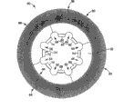
Fig. 1 shows the plane of the one exemplary embodiment of brush element of the present invention.
Fig. 2 shows the plane of the one exemplary embodiment of brush portion branch of the present invention.
Fig. 2 a is the amplification view of Fig. 2 interlock.
Fig. 3 is the cross-sectional view that 3-3 along the line Fig. 2 brush portion of cutting is divided.
Fig. 4 is an enlarged drawing, shows the enlarged drawing of a part of bristle of Fig. 2 brush portion branch.
Fig. 5 is a cross-sectional view, shows the one exemplary embodiment of the bristle of brush portion branch of the present invention.
Fig. 6 is a cross-sectional view, shows another one exemplary embodiment of the bristle of brush portion branch of the present invention.
Fig. 7 is a cross-sectional view, shows another one exemplary embodiment of the bristle of brush portion branch of the present invention.
Fig. 8 is a cross-sectional view, shows another one exemplary embodiment of the bristle of brush portion branch of the present invention.
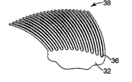
Fig. 9 is the partial elevation view that the brush element of Fig. 1 engages with a surface.
Figure 10 is local figure, shows the one exemplary embodiment that molded brush portion of the present invention is divided, and wherein bristle stretches out with respect to the radius of brush portion branch.
Figure 11 shows another one exemplary embodiment that brush portion of the present invention is divided, and wherein bristle is angled with respect to the radius of brush portion branch.
Figure 12 shows another one exemplary embodiment that brush portion of the present invention is divided, and wherein the bristle that extends from the central portion office that brush portion is divided is crooked.
Figure 13 is local figure, shows an one exemplary embodiment of brush assemblies of the present invention.
Figure 13 a is the plane of an one exemplary embodiment of brush assemblies of the present invention.
Figure 13 b is the plane of an one exemplary embodiment of brush assemblies of the present invention.
Figure 13 c is the plane of an one exemplary embodiment of brush assemblies of the present invention.
Figure 13 d is the sectional view of Figure 13 c brush assemblies of 13d-13d along the line.
Figure 14 shows the part figure of an one exemplary embodiment of the bristle pattern in the brush assemblies of the present invention.
Figure 15 shows the part figure of another one exemplary embodiment of the bristle pattern in the brush assemblies of the present invention.
Figure 16 shows the part figure of another one exemplary embodiment of the bristle pattern in the brush assemblies of the present invention.
Figure 17 shows the part figure of another one exemplary embodiment of the bristle pattern in the brush assemblies of the present invention.
Figure 18 can be used on the schematic diagram of carrying out the exemplary mold equipment in the method for the present invention.
Figure 19 is the front view of Figure 18 mould.
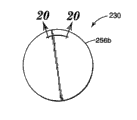
Figure 20 is the sectional view of the one exemplary embodiment of Figure 18 mould part of being cut of the line 20-20 along Figure 19.
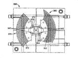
Figure 21 shows the view of the one exemplary embodiment of Figure 19 mould part.
Figure 22 shows the sectional view of another one exemplary embodiment of the brush portion branch made from the mould of Figure 20.
Figure 23 shows the part figure that comprises exemplary integrated disc portions, comprises the mould streamline that flows that shows material in making brush portion branch of the present invention.
Figure 24 shows the part figure of another one exemplary embodiment that brush portion of the present invention divides, show brush portion divide molded during the direction of mold flow.
Figure 25 is the plane that can be used for making the one exemplary embodiment of the mould that brush portion of the present invention divides.
Figure 26 a-b is the sectional view of the one exemplary embodiment of brush element.
The specific embodiment
In the following detailed description, will carry out reference to constituting its a part of accompanying drawing, show the present invention in the mode that can put into practice one exemplary embodiment of the present invention in the accompanying drawings.It should be understood that also and can use other embodiment, and can carry out structure or logical changes under the premise of not departing from the present invention.Therefore, should not think that following detailed description is circumscribed, protection scope of the present invention is defined by the following claims.
Usually, the present invention relates to be used for the brush element of abrasive brush.Described brush element comprises the exterior section that comprises bristle and comprises the interior section that is used for the interlock of interlocking adjacent brush when brush assemblies comprises a plurality of brush element.Individual brush elements also can comprise two or more independent brush portion branches.Use the part jockey together with the adjacent brush partial fixing.A plurality of brush elements can be piled up to form brush assemblies.Described brush assemblies can be used for treatment surface, such as in throw.
With reference to Fig. 1, wherein show an one exemplary embodiment of brush element of the present invention.Brush element 30 comprises the middle body 32 with internal edge 34 and external margin 36 that is generally annular.A plurality of bristles 38 stretch out from external margin 36.Interlock 42 is disposed in internal edge 34 places.Interlock 42 is constituted for interlocking molded brush element 30 and adjacent brush.Brush element can be configured so that to have whole middle body 32, and also can divide 80,82,84 and 86 to make by two or more brush portions.By jockey (for example, among Fig. 2 102) adjacent brush portion branch (for example 80,82) is fixed together.
But brush element 30 or brush portion divide 80 can make with moldable polymeric material, will describe its several examples hereinafter.Perhaps, each brush element or part can or be made by other technologies casting as known in the art.Brush element 30 or brush portion divide 80 material also can comprise abrasive grain.Described particle can be positioned at bristle 38 surfaces and go up or be dispersed on the bristle 38.Best, brush element 30 is molded as, so that bristle 38 and middle body 32 are mutually continuously.Interlock 42 also can be used as mould casting nozzle interface, is configured to be used to improve during brush element 30 molded edge 34 internally and to flow (as describing hereinafter) to the moulding material of external margin 36.
In an one exemplary embodiment, interlock 42 comprises joint element (for example, joint element 60) and is positioned at internal edge 34 places or is close to the receiving area (for example, the receiving area 44) of internal edge 34.The complementary interlock that interlock 42 engages on the adjacent brush relative to each other rotates with prevention brush element when brush element is stacked in the brush assemblies.
Shown in one exemplary embodiment in, brush element 30 comprises that edge 34 internally extends to a plurality of receiving areas 44,46,48,50,52,54,56,58 in the middle body 32.One or more receiving areas constitute the part of interlock 42.Brush element 30 also comprises a plurality of joint elements 60,62,64,66,68,70,72,74 of arranging along internal edge 34.In one aspect, each joint element is arranged between two receiving areas along internal edge 34.Interlock 42 comprises at least one receiving area (for example, the receiving area 44) and at least one joint element (for example, joint element 60).
Except that interlock 42, brush element also can comprise bossing or parts 85, and (for example, protuberance) arrangement is to help the alignment of adjacent brush.With the surperficial facing surfaces with bossing 85 on, each bossing 85 all will have corresponding reception inner chamber (not shown).Each bossing 85 all will be received in the corresponding reception inner chamber of adjacent elements.Each bossing 85 is received in the alignment of (as described hereinafter) adjacent brush in the time of will helping to form bristle pattern in its corresponding reception inner chamber and cooperates to prevent the relative rotation of adjacent brush with interlock.Best, bossing 85 radially separates around each brush element with the spacing identical with interlock.Under the situation of not using interlock, also can use the bossing on the adjacent brush and receive inner chamber to stop adjacent elements relative to each other to rotate.
Co-operating jockey 100,101 with the adjacent brush partial fixing together.Brush portion divides near 80,86 side margins 94 first jockeys 100 by middle body 32 to be fixed together.Brush portion divides near 80,82 side margins 964 second jockeys 101 by middle body 32 to be fixed together.Independently the brush portion branch is connected to adjacent brush portion branch to form brush element.Shown in one exemplary embodiment (Fig. 1 and Fig. 2) in, brush portion divides 80,82,84,86 to be connected to adjacent elements to form brush element 30.Can increase other method that is used for fixing adjacent part together with jockey, for example, seam between the welding portion or spot gluing.
Shown in one exemplary embodiment in, jockey 100,101 be constituted for brush portion divide 80 with 82,86 interlockings of adjacent brush part.Divide 80,86 jockeys that are fixed together 100 to comprise to be received in first attaching parts 102 in first FX 103 with brush portion.Divide 80,82 jockeys that are fixed together 101 to comprise to be received in second attaching parts 104 in second FX 105 with brush portion.What those skilled in the art should understand is, can use various suitable jockeys so that with a plurality of adjacent brush partial fixings together to form brush element.
With reference to Figure 13 a-c, two or more brush elements can be formed brush assemblies 200.Brush assemblies 200 is installed in usually and makes that on the rotary part (not shown) of brush assemblies rotation, described afterwards brush assemblies engages with the removal material or improves substrate or working surface with substrate or working surface.The hub assembly (not shown) of throw also can be connected with the interlock of brush element, thereby elimination or minimizing are used for the needs with the parts of brush assemblies and throw interlocking.
When brush assemblies rotated, each brush element is preferably rotation uniformly usually, and the relative rotation between the brush element can cause the suboptimum polishing on the substrate.Brush element of the present invention comprises and is used to eliminate the interlock that rotates between the adjacent brush.With reference to Fig. 1,2,2a, 13 and 13a-d, interlock 42 prevents that adjacent brush from relative to each other rotating.Each adjacent brush comprises that all edge 34 internally extends to complementary interlock in the middle body 32 (for example, comprise at least one receiving area, for example, receiving area 44 and a joint element are such as, joint element 62).Shown in one exemplary embodiment in, receiving area 44 is regular geometric shapes, for the part annular shape but can change into any suitable shape.Those of ordinary skills can understand other shapes that are fit to that are used for receiving area 44 after reading this specification.
Brush element 30 (Fig. 1) comprises a plurality of receiving areas 44,46,48,50,52,54,56,58 that separate around internal edge 34.Each receiving area 44,46,48,50,52,54,56,58 all receives and keeps its corresponding joint element 60,62,64,66,68,70,72,74.When a plurality of brush portion branches are used to form brush element, can between two adjacent brush parts, form the receiving area, such as receiving area 56.Receiving area 56 is formed between the adjacent discs part 80,86 and extends between adjacent discs part 80,86.Similarly, receiving area 46 extends between the adjacent discs part 80,82 and to extend and be formed between the adjacent discs part 80,82.
With reference to Fig. 2 and 2a, wherein show the one exemplary embodiment of interlock.Interlock 42 comprises the joint element of arranging along internal edge 34 62.Joint element 62 is arranged between receiving area 44 and 46.Joint element 62 comprises internal edge 112, first turning 114 and second turning 116.Shown in one exemplary embodiment in, first turning 114 and second turning 116 be normally right angle corner, but also can be other shapes, for example, has the turning of radian.Joint element 62 has first width (W1) and receiving area 44 has second width (W2) along internal edge 34.In an illustrated embodiment, the width of W1 and W2 is roughly the same, although those of ordinary skills can understand be the layout that also can use other to be fit to.With reference to Fig. 1, brush element 30 comprises eight regularly spaced interlocks 42, and wherein each receiving area and joint element all have roughly the same width.
With reference to Figure 13, wherein show the one exemplary embodiment of brush assemblies 200.Brush assemblies 200 comprises two adjacent brush element 30a, 30b.Brush element 30a, 30b promptly, are made the interlock 42a of brush element 30a cooperate with the relative rotation between restriction brush element 30a, the 30b with the interlock 42b of brush element 30b by so directed.The joint element 60b of brush element 30b is received among the receiving area 58a of brush element 30a and by receiving area 58a and keeps.The joint element 60a of brush element 30a is received among the receiving area 44b of brush element 30b and by receiving area 44b and keeps.Similarly, when not only an interlock is on each adjacent brush element, the interlock on each brush element all will with corresponding interlock cooperation on the adjacent brush to engage these brush elements and to limit relative rotation between the described brush element.
For example also can using, adhesive, securing member or other appropriate methodologies (those of ordinary skills are known) are fixed together adjacent brush element (for example 30a and 30b).By this way, any amount of brush element 30 all can be assembled in the brush assemblies 200 so that desired width to be provided together.
With reference to Fig. 3, wherein show the brush portion of being cut along the line 3-3 of Fig. 2 and divide 80 cross-sectional view.Joint element 62 comprises the increase thickness part 128 that is positioned at internal edge 34 places.Increase thickness part 128 has the thickness T 1 with respect to thickness T 2 increases of the middle body 32 at external margin 36 places.Joint element 62 is any shearing force of sufficient intensity to produce between the opposing adjacent brush preferably.Best, increase thickness part 128 up to greater than 50% of element middle body 92 thickness that are close to external margin 36, it can be bigger although depend on concrete interlock.When arranging adjacently with second brush element, the increase thickness part 128 of joint element 62 extends in the corresponding receiving area of second brush element and is used for this brush element and the adjacent second brush element interlocking.Each corresponding interlock all increases thickness part 128 places at each and is engaged in the adjacent brush of interlocking so that moving relative to circumference between the restriction brush element.
With reference to Fig. 4, wherein show a part of bristle 38 that brush portion is divided 80 (as shown in Figure 2).Bristle 38 divides middle body 92 whole formation with brush portion.Bristle 38 extends radially outwardly from external margin 36.In an illustrated embodiment, bristle 38 comprises the first bristle row 38a, and the described first bristle row 38a is spaced apart in the circumferential direction around external margin 36, and surface co-planar ground extension common and that brush portion is divided middle body 92.Bristle 38 also comprises the second bristle row 38b, departs from the first bristle row 38a.The second bristle row 38b extends radially outwardly and spaced apart with the bristle that is positioned at the first bristle row 38a from external margin 36.
Perhaps, brush portion divides 82 can comprise single row of bristles 38, or not only two arranges bristles 38.Each bristle 38 all comprises bristle root 132 and bristle tip 134.Each bristle 38 all extends from external margin 36 at the bristle root place.Shown in one exemplary embodiment in, the zone between the adjacent bristle roots normally circular or fillet, be expressed as 136.Be generally circular bristle root area and provide the intensity that increases from the position that brush portion divides the external margin 36 of middle body 92 to extend at each bristle 38.
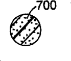
With reference to Fig. 5-8, wherein show several one exemplary embodiment of the bristle cross-sections that can be used for brush element of the present invention.With reference to Fig. 5, wherein show the cross-sectional area of an one exemplary embodiment.Bristle 38 has substantially and is the cross section of rectangle, has first square edge 142, second square edge 144, basic for circular edge 146 and be circular edge 148 substantially.Bristle 38 can have other shape of cross section, comprises the combination of circle, star, semilune, four/January shape, ellipse, rectangle, square, triangle, rhombus or other polygons or shape.Other exemplary shape of cross section: Fig. 6 have been shown at Fig. 6 in Fig. 8 and have shown bristle with circular 700 cross sections; Fig. 7 shows the bristle with the cross section that comprises semicircle 703 and square part 704; And Fig. 8 shows the bristle with square 701 cross sections.Bristle also can have constant cross section along the length of bristle 38, but also can have non-constant or variable cross section along the length of bristle.
That bristle 38 can be taper so that the cross-sectional area of bristle is along 134 direction reduces towards the tip away from root 132.Tapered bristle 38 can have any cross section, such as above-described those.As shown in Figure 9, bristle 38 stands bending stress when brush portion divides 92 to rotate on workpiece.These bending stresses are the highest at root 132 places (externally 36 places, edge) of bristle 38.Tapered bristle is resisted more bending stress than the bristle of constant cross-section area usually.Bristle 38 can have taper along whole length, perhaps can be adjacent to that root 132 places have tapering part and has constant cross-sectional area at the remainder of bristle 38.Described taper can be any suitable angle.In addition, brush portion divides 80 can divide the transition part office between the external margin 36 of middle body 92 to comprise radius of corner in bristle 38 roots 132 and brush portion.This concrete bristle pattern is included in the ken that those skilled in the art grasp.
Bristle 38 has and is restricted to from outside root 132 aspect ratio that 134 measured bristle 38 length draw divided by the bristle width to the tip.Under the situation of tapered bristle, in order to determine aspect ratio, described width is restricted to the mean breadth that draws along length.Under the situation of non-circular cross sections, width is got and is made the longest width in the given plane, such as the diagonal of square cross section.The aspect ratio of bristle 38 preferably is at least two, but also can be less (in certain embodiments, about 5 to 100, perhaps, and for example, from 50 to 75).Can from brush portion divide 80 and the concrete application of brush element 30 select the size of bristle 38.The width of bristle 38 can be identical or different with the thickness of middle body 92.In an one exemplary embodiment, all bristles 38 all have identical size.Perhaps, comprise that a plurality of brush portions divide the bristle 38 on 80,82,84,86 the element 30 to be of different sizes, such as having different length, width or cross-sectional area.For example, the brush portion branch can have short bristle group and long bristle group.And, can arrange the brush portion branch to constitute brush element, each brush portion is divided the bristle that all has different length.And, can use adjacent brush part with different bristles.
Can from employed brush portion divide 80 and the concrete application of brush element 30 select the density and the layout of bristle 38.Bristle 38 is arranged with the external margin 36 or the circumference of uniform interval along middle body 32 usually.Perhaps, have mode at interval between bristle 38 can be organized and be disposed in the group, and except that radially outward, also can be oriented in the plane of middle body 32, that is, become the mode orientation of non-zero angle with radius with respect to middle body 32.Therefore, brush portion divides 80 can have the part of the external margin 36 that does not comprise any bristle 38.Described bristle can exist only on the part of external margin 36 of middle body 32.Bristle 38 can according to the expectation against or not against adjacent bristle.
Can so select material, length and the structure of bristle, promptly make bristle 38 fully deflection to help the cleaning inhomogeneous or irregular workpiece.In certain embodiments, bristle 38 can bending at least 25 degree (in certain embodiments, be at least 45 degree, be at least 90 degree, perhaps even be approximately 180 degree), and can not damage bristle or bristle is caused substantial permanent deformation.
Therefore the structure that can be fit to strengthens bristle 38.For example, can in the bristle mold cavities, place reinforced fibers or line, and inject mouldable polymer around the gut threads, thus the gut threads or the fiber that make bristle 38 have to be embedded in wherein.
Figure 10-12 shows in the one exemplary embodiment that changes with respect to the bristle 38 aspect middle body 32 directed.In Figure 10, bristle 38 extends radially outwardly from the external margin 36 of middle body 32 substantially.In Figure 11, bristle 38 stretches out in the mode with respect to the external margin 36 angled γ of middle body 32.In Figure 12, bristle 38 stretches out agley from the external margin 36 of middle body 32.Those skilled in the art will understand other bristle configurations that are fit to that can be used for brush portion branch of the present invention after having read the application.
Figure 13 a-13b shows brush element 30a and 30b is arranged together to form an one exemplary embodiment of brush assemblies 200.Figure 13 a shows brush element 30a, and brush element 30a comprises the first first type surface 202a and the second first type surface 202b (not shown).Figure 13 b shows brush element 30b.Brush element 30b comprises the first first type surface 204a and the second first type surface 204b (not shown).Figure 13 c shows an embodiment of the brush assemblies 200 that comprises brush element 30a and 30b.In certain embodiments, brush element 30b edge member (for example, edge member 60b) is disposed in the receiving area of brush element 30a (for example, edge member 60b is disposed among the 44a of receiving area).Below with reference to Figure 13 d.It is relative with the second first type surface 202b of brush element 30a that the first first type surface 204a of brush element 30b is positioned to.Brush element 30a and brush element 30b (for example, using adhesive) secured together.Indicated as direction arrow 212, brush element 30b edge member is arranged in (or interlocking) in the receiving area of brush element 30a and has eliminated move (for example, circumference moves) between brush element 30a and the brush element 30b.
Brush element orientation relative to each other can obtain many different bristle pattern according to expectation in the brush assemblies by changing.Use the one exemplary embodiment brush portion branch shown in Fig. 1 and Fig. 2, four kinds of different bristle pattern are feasible.Figure 14,15,16 and 17 shows the brush portion that can use Fig. 2 and divides four kinds of different bristle pattern making.Interlock 42 repeats around internal edge 32 with the interval of 45 degree (that is the twice of angle α (Fig. 2)).Angle α is 22.5 degree and shows the symmetry of interlock 42 around radius R 1 and R2.The center point P that radius R 1 divides from brush portion is passed the center line of receiving area 44.Radius R 2 passes the center line of joint element 60 from center point P.Bristle on the part 80 is so arranged, that is, make to have two rows bristle alternately.Shown in one exemplary embodiment in, when four brush portion branches were formed a brush element, every row had 108 bristles, so each brush element all has with rule and is arranged in 216 bristles outside the brush element circumference at interval.After having read this specification, what those skilled in the art should understand is that other bristle pattern that allow single part to form a plurality of bristle pattern or layout also are feasible.Different bristle pattern can provide different finishing characteristics on workpiece or working surface.In addition, different bristle pattern can provide different effects on working surface or substrate.
With reference to Figure 14, partial illustration has gone out first one exemplary embodiment of alternating bristle pattern 220.By with respect to arranging that with the brush element 30a second first type surface 202b brush element 30b first first type surface 204a has obtained alternating bristle pattern 220.First bristle pattern by two adjacent brush elements at first so that they obtain in line with respect to its corresponding interlock.For example, will be disposed in the first brush element 30b upward so that their interlocks separately just align with reference to Fig. 1, Fig. 2 and 13, the second brush element 30a.Thereby make joint element 60b engage to produce bristle pattern 220 with receiving area 58a by making the brush element 30b that wins be rotated in a clockwise direction 22.5 degree.Also can obtain identical design by making the brush element 30b that wins rotate 67.5 degree (angle β) in the counterclockwise direction.In the plane that the bristle of the bristle of the first brush element 30b and the second brush element 30a is radially obtained between the middle body of each brush element alternately and overlapping.
With reference to Figure 15, wherein show second alternating bristle pattern 222.From identical starting point, obtain second alternating bristle pattern 222 by making the brush element 30b that wins rotate 22.5 degree in the counterclockwise direction from the alignment that is used to make first bristle pattern 220 or being rotated in a clockwise direction 67.5 degree.In this design, in the plane that the bristle of the bristle of the first brush element 30b and the second brush element 30a is radially obtained between the middle body of each brush element alternately and overlapping, but have the skew of about 90 degree or the skew of relative orientation (that is, the line a-a that obtains along the major axis of the first design 220a has the skew of about 90 degree with respect to the line b-b that obtains along the major axis of design 220b) with respect to the first design 220a.
With reference to Figure 16, wherein show the 3rd bristle pattern.By having formed the 3rd bristle pattern 224, as form first bristle pattern 220 so that the first and second brush element 30a and 30b overlap.Before any rotation of adjacent elements, make and win brush element 30b rotation or center on its radial centre lines (the line R2 among Fig. 2) rotation or reversing.Form bristle pattern 224 by making the first brush element 30b that reverses be rotated in a clockwise direction 22.5 degree to engage with interlock.Also can obtain identical design by making the brush element 30b that wins rotate 67.5 degree in the counterclockwise direction.The bristle of the bristle of the first brush element 30b and the second brush element 30a in line, as along shown in the center line (by the some P among Fig. 2) of each element.In this bristle pattern 224, alternating bristle between distance be variable.
With reference to Figure 17, by make the brush element 30b that wins further rotate in the counterclockwise direction 22.5 the degree or be rotated in a clockwise direction 67.5 the degree form second embark on journey the design 226.In this bristle pattern 226, alternating bristle between distance normally constant.
If only expect bristle pattern 220,222 alternately, brush element can comprise and be used to help alignment and prevent counterrotating bossing and reception inner chamber (as discussed previously) between the element.By using above-mentioned design, brush assemblies can be made to such an extent that comprise one or more described designs.In addition, in single brush assemblies, can use a plurality of designs.Those skilled in the art will be appreciated that by on the individual brush elements at interlock at interval and form symmetry between the bristle pattern and can produce other repeated bristle pattern.
Use various technology as known in the art, for example, jet moulding, pressing, die-cut method, sterolithography or casting can produce brush element of the present invention and brush portion branch.Usually,, use mouldable polymeric material when using injection molding manufactured brush of the present invention or brush portion timesharing, for example, thermoplastic polymer, thermoset polymer or thermoplastic elastomer (TPE).For those skilled in the art, the suitable material of the injection molding abrasive brush that is used to make is known and its selection will be depended on described brush portion branch and the employed concrete application of brush assemblies.A kind of concrete material that can be used in brush portion branch and the brush assemblies is commercially available segment polyester, comprise E.I.Du Pont de Nemours and Company, Inc., Wilmington, those that DE sells under trade name " HYTREL 4056 ", " HYTREL 5526 ", " HYTREL 5556 ", " HYTREL 6356 ", " HYTREL7246 " and " HYTREL8238 ".Similar thermoplastic polymer family is that the trade name " RITEFLEX " of Hoechst CelaneseCorporation is sold down.For example, in U.S. Patent No. 5,42, described the thermoplastic elastomer (TPE) that is fit among 595 people such as () Pihl, its full content mode is by reference incorporated among the application.
Brush element and brush portion are divided also can comprise abrasive grain.Abrasive grain can be positioned on polishing surface or the element (for example, bristle), is dispersed in wherein, or its combination.Even when causing bristle wearing and tearing or size to reduce owing to use, on all bristles, comprise abrasive grain and also can make the abrasive material quality of bristle keep constant relatively during use.For those skilled in the art, abrasive grain is known and the selection of abrasive grain and abrasive grain will depend on various factors comprising in brush element and part, comprises character and other operating conditions of surface of the work.In the ken that is chosen in those skilled in the art of concrete abrasive grain.The example of abrasive grain comprise aloxite (AI, heat treated aloxite (AI, ceramic alumina, heat treated aluminium oxide, carborundum, titanium dioxide, alumina zirconia, diamond, boron carbide, ceria, alumina silicate, cubic boron nitride, diamond dust, silica, with and combination.For example can be from Exolon ESK Company, Tonawanda, NY, and Washington MillsElectro Minerals Corp., North Grafton, MA buys aloxite (AI.The ceramic alumina abrasive grain that is fit to comprises U.S. Patent No. 4,314,827 people such as () Leitheiser; 4,744,802 (Schwabel); 4,770,671 (people such as Monroe); 4,881,951 (people such as Morris); 4,964,883 (people such as Morris); 5,011,508 (people such as Wald); And disclosed in 5,164,348 (people such as Wood) those, its full content mode is by reference incorporated among the application.The suitable a type alumina-based ceramic abrasive grain that comprises a type aluminium oxide and rare earth oxide comprises The 3M Company, St, Paul, those that MN sells under trade name " CUBITRON 321 ".Other examples that are used for particle of the present invention comprise solid glass ball, hollow glass ball, calcium carbonate, polymeric bubbles, silicate, aluminium trihydrate and mullite.When with binder phase and when forming the brush element that can repair surface of the work, abrasive grain can be any concrete material (inorganic or organic).Required concrete application will be partly depended in the selection of abrasives.For example, for the stripping paint of motor vehicle, preferably save the abrasive grain of brush element sometimes.When stripping paint, preferably use softer abrasive grain sometimes so that can not damage surface below the coating.Perhaps, in order to get on except that burr, preferably use harder abrasive grain usually, such as what make with a type aluminium oxide from metal works.In those embodiment that comprise optional abrasive grain, brush element of the present invention can comprise the abrasive grain of two or more types and/or size.
When using in the text, the term abrasive grain also comprises single abrasive grain, and described single abrasive grain can be bonded together to form the abrasive material piece.In some instances, add polishing and the treatment characteristic that coating has improved abrasive grain.For example,, can find the example of abrasive material piece among 508 (people such as Wald), merge here with reference to its full content in U.S. Patent No. 5,011.
The organic abrasive grain that is suitable for using with brush element of the present invention comprises those that form with thermoplastic polymer and/or thermosetting polymer.Spendable organic abrasive grain can be individual particles or agglomerates of individual particles among the present invention.Described particulate mass can comprise that a plurality of organic abrasive grain that is bonded together by adhesive is to form forming blocks.
Be used to make the polymeric material that brush element of the present invention and brush portion divide and also can comprise grinding aid.Grinding aid is a kind of like this granular materials, that is, being added on chemistry and the physics grinding process of it has remarkable result, thereby causes augmented performance.The example of the chemical race of grinding aid comprises wax, organohalogen compounds composition, halide salts and metal and alloy thereof.The organohalogen compounds composition will decompose and discharge halogen acids or gaseous halide composition usually during polishing.The example of described material comprises chlorinated wax, is similar to Tetrachloronaphthalene (tetrachloronaphthalene), Pentachloronaphthalene (pentachloronaphthalene) and polyvinyl chloride.The example of halide salts comprises sodium chloride, elpasolite, sodium cryolite, ammonium ice crystal, potassium tetrafluoroborate, sodium tetrafluoroborate, silicon fluoride, potassium chloride, magnesium chloride.The example of metal comprises tin, lead, bismuth, cobalt, antimony, cadmium, iron and titanium.Other grinding aids of different nature comprise sulphur, sulfur-containing organic compound, graphite and metal sulfide.
Can be by for example injection molding manufactured brush element of the present invention or brush portion branch.Jet moulding is as known in the art.Take notice of to have illustrated among Figure 18 and be used to make the exemplary injection molding equipment that the related brush portion of the inventive method is divided.Usually, by heating after the drying, but the mixture that comprises the bead of molded polymer and (randomly) abrasive grain is placed in the loading hopper 242.Loading hopper 242 supplies to mixture first or the rear side 250 of the screw rod injector 244 that comprises the screw rod 246 in the bucket 248 usually.The opposite side of screw rod injector 244 or first side 252 comprise and are used for making that softening mixture enters into the nozzle 254 of mould 256a, 256b.The bucket 248 of injector 244 is heated with fusion mixture, and the screw rod 66 of rotation is along the direction propelling mixture of nozzle 254.Screw rod 246 moves so that under desired pressure softening mixture " is penetrated " to go among mould 256a, the 256b along direction B is linear forward afterwards.Between the front end of screw rod and nozzle, maintain the gap usually so that " buffering " zone of the softener material that is not injected in the mould to be provided.
For example, can prepare above-mentioned bead as described as follows.Can heat mouldable polymer more than the fusing point at it, can incorporate into optional abrasive grain according to expectation afterwards.Afterwards formed mixture is formed continuous tow, and described tow is cooled so that solidify mouldable polymer, so that on the device that is fit to, form spherical as known in the art like that.Similarly, in the formation of bead, can comprise lubricant and/or other additives that is incorporated in the polymeric material.The bead that comprises mouldable polymer, abrasive grain and any desired lubricant and/or other additives afterwards is placed in the loading hopper 242 so that be fed into like that in the screw rod injector 244 as mentioned above.
For example determine brush portion branch injected molding under which kind of condition by employed injection molding device, the structure of brush portion branch and the composition of mouldable polymer and abrasive grain.In an exemplary method, mouldable polymer in 70 ℃ to 120 ℃ scope (in certain embodiments, in 80 ℃ to 100 ℃ scope) at first be heated so that carry out drying, and be placed in the loading hopper 242 so that supply in the screw feed zone by gravity.The barrel temperature of screw rod injector is more preferably from 220 ℃ to 245 ℃ preferably from 200 ℃ to 250 ℃.The temperature of mould is more preferably from 100 ℃ to 140 ℃ preferably from 50 ℃ to 150 ℃.Be preferably in circulation timei (mould is to take out the time that molded brush portion is divided from mixture is being incorporated into the screw extruder to opening) in 0.5 to 180 second the scope, be more preferably, in from 5 to 60 seconds the scope.Expulsion pressure is preferably from 690 to 6900kPa (100 to 1000psi), is more preferably, from 2070 to 4830kPa (300 to 700psi).Be used in the knowledge category that is chosen in those skilled in the art of concrete operations condition of injection molding, and depend on concrete application, can change beyond the given example ranges.
Injection mold cycle will depend on material composition and brush portion separation structure.In an one exemplary embodiment making the brush portion branch, mouldable polymer and abrasive grain are distributed to all brush portions equably usually and are divided on 80.In such an embodiment, the single that has the mixture of mouldable polymer and abrasive grain is inserted or injects with molded brush portion branch, if present, comprise middle body, bristle and jockey.Perhaps, bristle can comprise abrasive grain, and middle body does not comprise abrasive grain.In such an embodiment, will there be twice insertion of material or inject.Insert for the first time and will comprise the mixture of mouldable polymer and abrasive grain so that mainly fill the bristle part of mould.Insertion for the second time will comprise mouldable polymer (can be identical or different with the mouldable polymer that inserts for the first time) and not have abrasive grain so that mainly fill the middle body and the root of mould.Similarly, middle body and bristle can comprise abrasive grain, and root can not comprise abrasive grain.In this structure, will there be twice insertion of material or inject.Insert the mixture that will comprise mouldable polymer and abrasive grain for the first time so that fill the bristle and the middle body of mould.Insert for the second time and will only comprise mouldable polymer (can be identical or different) so that mainly fill the jockey part of mould with the mouldable polymer that inserts for the first time.If desired, can use the color of injecting more than once with change brush portion branch different piece.Can use three times or repeatedly inject, for example each uses once for bristle, middle body and jockey.After injection molding, mould is cooled to solidify mouldable polymer.Two halves with mould separate to take out molded brush portion branch afterwards.
With reference to Figure 23, wherein show an embodiment of mold flow properties during molded brush portion branch (for example, molded brush portion divide 80).Interlock 42 is as the mould gate interface that is positioned at internal edge 34 places, is used for dividing 80 molding process to improve from inward flange 34 to outward flange in 36 the mould in brush portion and flows.The mould streamline is represented with 300.In brush portion is divided 80 molding process, make that preferably the length of mould streamline is equal substantially, cause flowing in the even mould of outward flange 36 and flow.Edge member 60,62 direct and mold gate interlockings.Receiving area 58,56 and 46 is used to guide in the mould flows, cause flowing to flow in the mould of outward flange 36 more even.In addition, the thickness augmenting portion 128 that is close to mould gate cause flowing to flow in the mould of outward flange 36 more even.Molded brush portion is divided 80 needs moulding material seldom, and this is because the existence of receiving area 58,44 and 46.
Referring to Figure 24, show the optimized molded brush portion that in the molding process that molded brush portion is divided, is used for flowing in the mould and divide an embodiment of 80.Molded brush portion divides 80a also to comprise opening 310,312,314.Opening 310,312,314 provides the optimization that flows in the further mould in molded brush portion is divided 80 molding process.Opening 310,312,314 provides the further guiding of flowing in the mould, shown in flow vector 320.
Referring to Figure 25, show an embodiment who is used to make the mould 350 that brush portion divides of the present invention.Two different brush portions divide 360,370 to be fabricated on the mould 350.Brush portion divides 360 to comprise curved bristles 352.Brush portion divides 370 to comprise straight bristles.Usually, the diameter that each brush portion is divided is about 8 inches (203.2 millimeters), although other sizes also are fine according to the present invention.Each joint element 354,374 docks with corresponding mould gate 353,373.By mould gate being arranged on the thickness augmenting portion place of joint element 354,374, as mentioned above, interior the flowing of mould that adds mould is enhanced.Although this shown embodiment makes the brush portion branch, mould also can be designed to make other combinations, for example, and brush element or similar or different brush portion branch more or less.
Now referring to Figure 26 a-b, wherein show diameter and be the cross-sectional view of embodiment of brush element of the brush of about 8 inches (203.2 millimeters), similar with Fig. 3.Referring to Figure 26 a, wherein show brush element with curved bristles, core thickness T C1 is about 0.050 inch (1.27 millimeters).In each side of joint element, thickness augmenting portion TP1 (at interlock arrangement joint element place) is about 0.094 inch (2.39 millimeters), and thickness augmenting portion TI1 is about 0.022 inch (0.559 a millimeter).In another embodiment, the brush element of Figure 26 a can be done thicklyer, comprises that core thickness T C1 is about 0.062 inch (1.57 millimeters).In each side of joint element, thickness augmenting portion TP1 (at interlock arrangement joint element place) is about 0.120 inch (3.05 millimeters), and thickness augmenting portion TI1 is about 0.016 inch (0.406 a millimeter).Referring to Figure 26 b, show brush element with straight bristle, comprise that core thickness T C2 is about 0.050 inch (1.27 millimeters).In each side of joint element, thickness augmenting portion TP2 (at interlock arrangement joint element place) is about 0.094 inch (2.39 millimeters), and thickness augmenting portion TI2 is about 0.022 inch (0.559 a millimeter).In another embodiment, the brush element of Figure 26 b can be done thicklyer, comprises that core thickness T C2 is about 0.062 inch (1.57 millimeters).In each side of joint element, thickness augmenting portion TP2 (at interlock arrangement joint element place) is about 0.120 inch (3.05 millimeters), and thickness augmenting portion TI1 is about 0.016 inch (0.406 a millimeter).It will be understood by those skilled in the art that brush element of the present invention and partly can utilize the combination of a plurality of parameters to make, for example the bristle size and dimension coils radius, core thickness and above-mentioned example and is used to illustrate.
As mentioned above, brush element of the present invention, brush portion branch and brush assemblies can be used for finish.An one exemplary embodiment of the method for finish comprises following one or more steps: a part of removing surface of the work; Workpiece is carried out surfacing; The cleaning surface of the work comprises and removes coating or other coatings, filler, burn into or other foreign matters; Or some combinations of abovementioned steps.In an one exemplary embodiment shown in Figure 13 b, brush assemblies 200 comprises a plurality of brush elements 30 and the suitable drive unit that is fixed in axle by jockey.Perhaps, element 30 can be installed in suitable rotating driving device, such as commercially available right angle grinders.Surface finish can be dry or moistening, as water, lubricant, anticorrosive additive, or other liquid that are fit to, as known in the art.Brush assemblies 200 can rotate under any suitable speed, is preferably in up to 15, and 000RPMs or be low to moderate down rotation of 100RPMs is although also can use higher or lower speed if desired.Can carry out surface finish by acting on any suitable power that brush assemblies or brush portion divide, described power is usually up to 100kg or be low to moderate 0.5kg, although also can use greater or lesser power.It should be noted that bristle 38 is abundant deflection and softness, so that under the operation of finishing many times, bristle is to carry out along the whole length of bristle sidepiece with contacting of workpiece, and is not only the sub-fraction bristle that is adjacent to tip 134.By using the abrasive grain described in the literary composition, or by saving abrasive grain 41, molded bundle part or brush assemblies can be used for removing foreign matter from surface of the work, for example coating, dust, fragment, greasy dirt, oxide coating, iron rust, adhesive, filler etc., and can not remove lot of materials from workpiece itself.
With reference to its some embodiment the present invention has been described.Aforementioned detailed description and example only provide for the purpose of understanding.Should therefrom not be interpreted as unnecessary limitations.What those skilled in the art should understand is can make many changes under the situation that does not break away from protection domain of the present invention in described embodiment.For example, as known in the art, molded brush portion of the present invention is divided can have the device that is used for by the opening that passes backing or bristle fluid (such as cooling agent, lubricant and cleaning fluid) being incorporated in operation workpiece.Therefore, protection scope of the present invention should not be limited to the structure described in actual description and the literary composition, but is subject to the described structure of language of claim, and the equivalent of those structures.
Although illustrated and described specific embodiment for illustrative purposes; what but those skilled in the art should understand is; under the situation that does not break away from protection domain of the present invention, be used to realize that the various replacements of identical purpose and/or manner of execution of equal value can be substituted by specific embodiment shown and that describe.Can easily understand chemistry, machinery, electric mechanical, electricity and the experienced personnel of computer realm, can in various embodiments, carry out the present invention.The application trends towards covering any reorganization and the variation of the one exemplary embodiment disclosed in the literary composition.Therefore, this means that obviously the present invention is limited by claim and equivalent thereof only.
Claims (48)
1. molded brush element that is used for radial brushes comprises:
Circular middle body with external margin and internal edge;
The a plurality of bristles that extend out from external margin; And
Be arranged in the interlock at internal edge place, be configured for this brush element and other brush element interlocking, described interlock comprises at least one joint element.
2. according to the described brush element of claim 1, it is characterized in that described interlock comprises at least one receiving area that edge internally extends out.
3. according to the described brush element of claim 2, it is characterized in that described receiving area comprises the geometry of rule.
4. according to the described brush element of claim 3, it is characterized in that described receiving area is a part circular.
5. according to the described brush element of claim 2, it is characterized in that described joint element is arranged along internal edge, between first receiving area and second receiving area.
6. according to the described brush element of claim 5, it is characterized in that described joint element comprises the internal edge between first turning and second turning.
7. according to the described brush element of claim 6, it is characterized in that described first turning and second turning are the circular arc type turnings.
8. according to the described brush element of claim 5, it is characterized in that described joint element has first width, and first receiving area has second width along internal edge, and it is characterized in that described first width is substantially equal to second width.
9. according to the described brush element of claim 5, it is characterized in that described joint element has the thickness of increase with respect to the thickness of the middle body that is close to external margin at the internal edge place.
10. according to the described brush element of claim 9, it is characterized in that the thickness of described increase is up to the thickness thick 50% than the middle body at external margin place.
11. according to the described brush element of claim 1, it is characterized in that, described middle body comprises at least two brush portion branches, and it is characterized in that, each brush portion is divided and is all comprised first side margins and second side margins, and comprises first sidepiece jockey that is positioned at the first side margins place and the second sidepiece jockey that is positioned at the second side margins place.
12., it is characterized in that described brush element is made with mouldable polymeric material according to the described brush element of claim 1.
13., also comprise abrasive grain according to the described brush element of claim 12.
14., it is characterized in that described polymeric material is the thermoplastic polymeric material according to the described brush element of claim 12.
15., it is characterized in that described polymeric material is a thermoset polymerization material according to the described brush element of claim 12.
16., it is characterized in that described interlock is configured for the hub element locking with throw according to the described brush element of claim 1.
17. be used to make the method for molded brush element, described method comprises:
Limit a kind of mould structure that is used for molded brush element, described brush element comprises the generally planar middle body with external margin and internal edge, the a plurality of bristles that extend out from external margin, and the interlock that comprises the increase thickness part that is positioned at the internal edge place, described interlock is formed to such an extent that be used for brush element and the second molded brush element interlocking molded with;
But the heating moldable polymeric material is so that form flowable materials; And
Under pressure, flowable materials is injected in the described mould structure to form brush element.
18. the described method of claim 17:
It is characterized in that the step of described qualification mould structure comprises limiting to have and is used to make the mould structure of material by the door that increases thickness and partly flow; And
It is characterized in that the step of described injection flowable materials comprises by described door injects flowable materials.
19. a brush assemblies comprises:
A plurality of molded brush elements, each described molded brush element all comprises:
Generally planar middle body with external margin and internal edge;
The a plurality of bristles that extend out from external margin;
Be arranged in the interlock at internal edge place, be formed to such an extent that be used for the adjacent brush element of interlocking.
20. according to the described brush assemblies of claim 19, described interlock comprises:
Edge extends to the one or more receiving areas in the generally planar middle body internally; And
Equal a plurality of joint elements of the quantity of receiving area along its quantity of internal edge layout.
21., it is characterized in that described interlock is configured for first brush element of interlocking along the circumferential direction and second brush element according to the described brush assemblies of claim 19, thereby stop first brush element and second brush element relative to each other to rotate.
22. a molded brush assemblies comprises:
The first molded brush element comprises:
The first generally planar brush portion with the first element-external edge and first element internal edge is divided middle body;
The a plurality of bristles that extend out from the first element-external edge;
Be arranged in first interlock of the first element internal edge,
The second molded brush element comprises:
The second generally planar brush portion with the second element-external edge and second element internal edge is divided middle body;
The a plurality of bristles that extend out from the second element-external edge;
Be arranged in second interlock of the second element internal edge,
Described first interlock and second interlock are formed to such an extent that be used for the interlocking first molded brush element and the second molded brush element.
23. a molded brush element comprises:
The molded brush portion branch of a plurality of interlockings, each described molded brush portion is divided and is all comprised:
Generally planar middle body, described middle body has external margin and internal edge, first side margins and second side margins, and comprises first sidepiece jockey that is positioned at the first side margins place and the second sidepiece jockey that is positioned at the second side margins place;
The a plurality of bristles that extend out from external margin; And
Be positioned at the interlock at internal edge place,
It is characterized in that described a plurality of molded brush portions are divided at the first sidepiece jockey and the second sidepiece jockey place by the molded brush element of interlocking with the looping shape.
24. the brush assemblies of a rotation comprises:
At least two brush elements, each brush element all comprises:
The molded brush portion branch of a plurality of interlockings, each described molded brush portion is divided and is all comprised:
Generally planar middle body, described middle body has external margin and internal edge, first side margins and second side margins, and comprises first sidepiece jockey that is positioned at the first side margins place and the second sidepiece jockey that is positioned at the second side margins place;
The a plurality of bristles that extend out from external margin; And
Be positioned at the interlock at internal edge place,
It is characterized in that described a plurality of molded brush portions are divided at the first sidepiece jockey and the second sidepiece jockey place by interlocking with the looping shape.
25. a molded brush assemblies comprises:
A plurality of molded brush elements that pile up adjacent one another are, each described molded brush element all comprises the molded brush portion branch of a plurality of interlockings, each described molded brush portion is divided and is all comprised:
Generally planar middle body, described middle body has external margin and internal edge, first side margins and second side margins, and comprises first sidepiece jockey that is positioned at the first side margins place and the second sidepiece jockey that is positioned at the second side margins place;
The a plurality of bristles that extend out from external margin; And
Be positioned at the interlock at internal edge place,
It is characterized in that described a plurality of molded brush portions are divided at the first sidepiece jockey and the second sidepiece jockey place by the molded brush assemblies of interlocking with the looping shape.
26. a molded brush portion branch comprises:
Generally planar middle body with external margin and internal edge;
Interlock on the internal edge;
The a plurality of bristles that extend out from external margin, described bristle and generally planar Unitarily molded the forming of middle body, each bristle all comprises the root that is adjacent to external margin, and the root of wherein said vicinity externally edge limits the semicircular in shape zone.
27., it is characterized in that described a plurality of bristles substantially radially extend from external margin according to the described brush portion branch of claim 26.
28. according to the described brush portion branch of claim 27, it is characterized in that, substantially radially described a plurality of bristles of Yan Shening arcuate shape normally.
29., it is characterized in that each part all comprises 54 regularly spaced bristles according to the described brush portion branch of claim 27.
30. the brush portion branch of a rotation comprises:
The arcuate center part, described middle body comprises first and second side margins, described middle body also is included in the inside and outside edge that extends between described first and second side margins;
First jockey on first side margins and second jockey on second side margins; And
Interlock on the internal edge.
31., it is characterized in that described arcuate center partly is a quadrant shape part according to the described brush portion branch of claim 30.
32., it is characterized in that described bristle is disposed among two rows along external margin according to the described brush portion branch of claim 31.
33., it is characterized in that described bristle is crooked bristle according to the described brush portion branch of claim 31.
34., it is characterized in that described brush portion branch is made with thermoplastic according to the described brush portion branch of claim 30.
35., it is characterized in that described thermoplastic is a thermoplastic elastic material according to the described brush portion branch of claim 34.
36., it is characterized in that described bristle comprises abrasive grain according to the described brush portion branch of claim 31.
37. a brush assemblies comprises:
First and second brush elements, each brush element all comprises:
Have the generally planar middle body of external margin and internal edge, described flat has first and second surfaces;
From the outward extending a plurality of bristles of external margin;
Be arranged in the interlock at internal edge place;
At least one protruding part that extends from the first surface of each brush element;
With the corresponding inner chamber of each protruding part, be positioned at each protruding part and arrange thereon on the opposing second surface; And
It is characterized in that the cooperation of described interlock is so that stop first and second brush elements relative to each other to rotate, and each protruding part on first brush element is received in the corresponding inner chamber on second brush element.
38., also comprise the adhesive material between first and second brush elements according to the described brush assemblies of claim 37.
39., it is characterized in that each brush assemblies all comprises the array of the protruding part of the equidistant intervals that radially separates according to the described brush assemblies of claim 37.
40., it is characterized in that described protruding part separates with the interval at 22.5 degree angles according to the described brush assemblies of claim 39.
41., it is characterized in that described protruding part is round-shaped according to the described brush assemblies of claim 37.
42. a molded brush element comprises:
Have the generally planar middle body of internal edge and external margin, described flat has first and second surfaces;
From the outward extending a plurality of bristles of external margin;
Be arranged in the interlock at internal edge place;
A plurality of protruding parts from the first surface extension;
With the corresponding inner chamber of each protruding part, be positioned at each protruding part and arrange thereon on the opposing second surface.
43., it is characterized in that each brush element all comprises the array of the protruding part of equidistant intervals according to the described brush element of claim 42.
44., it is characterized in that described protruding part separates with the interval at 22.5 degree angles according to the described brush element of claim 43.
45., it is characterized in that described protruding part is round-shaped according to the described brush element of claim 42.
46., it is characterized in that described brush element comprises at least two brush portion branches according to the described brush element of claim 42.
47., it is characterized in that described brush element comprises the brush portion branch of four consistent shapes according to the described brush element of claim 46.
48., it is characterized in that each described brush element all comprises the jockey that is used for each part is connected at least one adjacent part according to the described brush element of claim 46.
Applications Claiming Priority (2)
| Application Number | Priority Date | Filing Date | Title |
|---|---|---|---|
| US10/389,788 | 2003-03-17 | ||
| US10/389,788 US7121937B2 (en) | 2003-03-17 | 2003-03-17 | Abrasive brush elements and segments |
Publications (2)
| Publication Number | Publication Date |
|---|---|
| CN1761417A CN1761417A (en) | 2006-04-19 |
| CN100446694C true CN100446694C (en) | 2008-12-31 |
Family
ID=32987434
Family Applications (1)
| Application Number | Title | Priority Date | Filing Date |
|---|---|---|---|
| CNB2004800074480A Expired - Lifetime CN100446694C (en) | 2003-03-17 | 2004-01-26 | Abrasive brush elements and segments |
Country Status (11)
| Country | Link |
|---|---|
| US (1) | US7121937B2 (en) |
| EP (1) | EP1603427B1 (en) |
| JP (1) | JP4693770B2 (en) |
| KR (1) | KR101107857B1 (en) |
| CN (1) | CN100446694C (en) |
| AT (1) | ATE412351T1 (en) |
| AU (1) | AU2004222415A1 (en) |
| BR (1) | BRPI0408416A (en) |
| CA (1) | CA2519428A1 (en) |
| DE (1) | DE602004017433D1 (en) |
| WO (1) | WO2004082429A2 (en) |
Families Citing this family (23)
| Publication number | Priority date | Publication date | Assignee | Title |
|---|---|---|---|---|
| PL1524078T3 (en) * | 2003-10-14 | 2015-06-30 | Tenax Spa | Working system using brush tool |
| US7081043B2 (en) * | 2004-01-14 | 2006-07-25 | 3M Innovative Properties Company | Molded abrasive brush and methods of using for manufacture of printed circuit boards |
| US8105134B2 (en) * | 2005-01-25 | 2012-01-31 | Epoxi Tech, Inc. | Low pressure polishing method and apparatus |
| US20050282474A1 (en) * | 2004-06-17 | 2005-12-22 | Wagner Spray Tech Corporation | Powered paint preparation tool, kit and method |
| JP2008096948A (en) * | 2006-09-12 | 2008-04-24 | Ricoh Co Ltd | Image forming apparatus and process cartridge |
| GB2444774A (en) * | 2006-12-13 | 2008-06-18 | Brush Technology Ltd | Rotary Brush |
| JP5306619B2 (en) * | 2007-09-06 | 2013-10-02 | スリーエム イノベイティブ プロパティズ カンパニー | Linear polishing brush member, method for manufacturing linear polishing brush member, and polishing brush |
| US20110126961A1 (en) | 2009-12-02 | 2011-06-02 | Bridgestone Bandag, Llc | Passive buffer brush air cooling |
| EP2616219A4 (en) * | 2010-09-15 | 2015-05-27 | Saint Gobain Abrasives Inc | Abrasive impregnated brush |
| CN102049396A (en) * | 2010-12-16 | 2011-05-11 | 中国人民解放军91872部队 | Cleaning head device |
| DE102011114916B4 (en) * | 2011-10-06 | 2019-12-19 | Eve Ernst Vetter Gmbh | radial brush |
| DE102011122106A1 (en) * | 2011-12-22 | 2013-06-27 | Carl Freudenberg Kg | Broom block with bristle structure |
| US20130331003A1 (en) * | 2012-05-17 | 2013-12-12 | Nils Eric Simonsen | Systems and methods for machine polishing a pattern onto metal using abrasive disks |
| ITBO20120571A1 (en) * | 2012-10-19 | 2014-04-20 | Daniele Trasforini | METHOD OF REALIZATION OF A BRUSH AND BRUSH OBTAINED THEN. |
| US9538835B2 (en) * | 2014-10-29 | 2017-01-10 | Herman Grewal | Bristle extruding toothbrush |
| CN105124916A (en) * | 2015-08-26 | 2015-12-09 | 安徽振达刷业有限公司 | Sweeping brush production method |
| CN105231653A (en) * | 2015-08-26 | 2016-01-13 | 安徽振达刷业有限公司 | Method for producing bristles without deforming or falling for long time |
| DE102016220766B4 (en) * | 2016-10-21 | 2018-08-23 | Boeck Gmbh | Tool for editing an object |
| USD848691S1 (en) * | 2017-11-15 | 2019-05-14 | Steven M Antler | Bristles of a brush |
| JP7212457B2 (en) * | 2018-04-27 | 2023-01-25 | 小林製薬株式会社 | interdental cleaner |
| USD899095S1 (en) * | 2019-12-30 | 2020-10-20 | Freeman Gormany | Powered toilet bowl brush |
| DE102022117629A1 (en) | 2022-07-14 | 2024-01-25 | Eve Ernst Vetter Gmbh | Radial brush for grinding or polishing purposes |
| CN115366015B (en) * | 2022-09-20 | 2023-08-15 | 广东捷骏电子科技有限公司 | Preparation method of ceramic brush wheel |
Citations (12)
| Publication number | Priority date | Publication date | Assignee | Title |
|---|---|---|---|---|
| GB223163A (en) * | 1924-05-07 | 1924-10-16 | Laurits Henrik Nielsen | Improvements in and relating to rotary brushes |
| US2821729A (en) * | 1955-02-16 | 1958-02-04 | Pittsburgh Plate Glass Co | Means for locking brush bristles in retaining structures |
| US2877481A (en) * | 1955-01-05 | 1959-03-17 | Pittsburgh Plate Glass Co | Rotary brush sections |
| US3233272A (en) * | 1964-03-23 | 1966-02-08 | Pambello Samuel Michael | Rotary brush |
| US3851350A (en) * | 1973-08-06 | 1974-12-03 | Mfg Brush Co | Interlocking rotary brush construction |
| CN2260502Y (en) * | 1996-09-10 | 1997-08-27 | 阎宝福 | Steel-wire wheel brush |
| DE29620104U1 (en) * | 1996-11-19 | 1998-03-19 | Wesumat Gmbh | Strip-shaped working element for washing, drying and polishing rollers |
| DE19818499A1 (en) * | 1997-05-02 | 1999-01-07 | Wesumat Gmbh | Washing roll for car wash |
| US5903951A (en) * | 1995-11-16 | 1999-05-18 | Minnesota Mining And Manufacturing Company | Molded brush segment |
| DE19843583A1 (en) * | 1998-09-23 | 2000-04-06 | Harald Vorbach | Washing element production and fixing to roller comprises use of strip of base material with zigzag edges and rounded points |
| CN2382286Y (en) * | 1999-07-18 | 2000-06-14 | 段梦麟 | Steel wire roll brush |
| CN1371643A (en) * | 2001-02-28 | 2002-10-02 | 林心正 | Steel brush with high-rigity abrasive grain and making method thereof |
Family Cites Families (55)
| Publication number | Priority date | Publication date | Assignee | Title |
|---|---|---|---|---|
| US3080657A (en) | 1963-03-12 | Lanski | ||
| JPS4212265Y1 (en) * | 1965-03-25 | 1967-07-11 | ||
| US3643281A (en) * | 1969-01-06 | 1972-02-22 | Mfg Brush Co The | Rotary brush |
| US3641611A (en) * | 1969-10-06 | 1972-02-15 | Manufactures Brush Co The | Brush construction |
| US4307479A (en) | 1979-10-19 | 1981-12-29 | Superior Brush Company | Angle tufted rotary brush assembly |
| US4422986A (en) | 1981-09-23 | 1983-12-27 | Cole William E | Method and apparatus for infection molding brushes |
| JPS59114018U (en) * | 1983-01-21 | 1984-08-01 | 昭和工業株式会社 | rotating brush |
| JPS6134926U (en) * | 1984-08-07 | 1986-03-04 | 一雄 石川 | Disc brush for roll brush |
| DE3444763A1 (en) * | 1984-12-07 | 1986-06-12 | Oskar Dilo Maschinenfabrik Kg, 6930 Eberbach | PLANT FOR THE PRODUCTION OF STRUCTURED TEXTILE VELOUR NEEDLE FELT FILMS |
| DE8718053U1 (en) | 1987-04-02 | 1993-03-04 | Jakob Reislaender Fabrik Technischer Buersten Gmbh, 8000 Muenchen, De | |
| US5045091A (en) | 1987-06-26 | 1991-09-03 | Minnesota Mining And Manufacturing Company | Method of making rotary brush with removable brush elements |
| US5928589A (en) | 1987-12-28 | 1999-07-27 | Teijin Limited | Processing for producing shaped wholly aromatic polyamide resin composition article and shaped article produced thereby |
| US4989166A (en) | 1988-07-12 | 1991-01-29 | Hitachi, Ltd. | Method for synthesizing analysis model and flow analysis system |
| JPH0620417Y2 (en) * | 1990-05-18 | 1994-06-01 | 株式会社バーテック | Roll brush |
| US5632790A (en) | 1990-05-21 | 1997-05-27 | Wiand; Ronald C. | Injection molded abrasive article and process |
| DE69018070T2 (en) | 1990-06-28 | 1995-08-10 | Boucherie Nv G B | Brush making machine. |
| US6069080A (en) | 1992-08-19 | 2000-05-30 | Rodel Holdings, Inc. | Fixed abrasive polishing system for the manufacture of semiconductor devices, memory disks and the like |
| DE4306965C1 (en) | 1992-10-19 | 1994-04-28 | Starck H C Gmbh Co Kg | Process for producing abrasive grains |
| US5400458A (en) | 1993-03-31 | 1995-03-28 | Minnesota Mining And Manufacturing Company | Brush segment for industrial brushes |
| US6083445A (en) | 1993-07-13 | 2000-07-04 | Jason, Inc. | Method of making a plateau honing tool |
| US6129620A (en) | 1993-04-23 | 2000-10-10 | Jason Incorporated | Honing tool and method of making |
| US5367833A (en) | 1993-10-22 | 1994-11-29 | Extrude Hone Corporation | Unidirectional abrasive flow machining |
| JPH07204999A (en) | 1994-01-07 | 1995-08-08 | Hotani:Kk | Method of polishing metal strip |
| US5438728A (en) | 1994-03-18 | 1995-08-08 | Minnesota Mining And Manufacturing Company | Rotary brush with segmented fiber sections |
| US5722106B1 (en) | 1995-02-01 | 2000-06-06 | Gillette Canada | Tooth polishing brush |
| WO1996025067A1 (en) | 1995-02-16 | 1996-08-22 | Noblecrest Marketing Pty. Ltd. | A sweeping device |
| MX9708204A (en) | 1995-04-28 | 1997-12-31 | Minnesota Mining & Mfg | Abrasive article having a bond system comprising a polysiloxane. |
| USD381139S (en) | 1995-04-28 | 1997-07-15 | Minnesota Mining And Manufacturing Company | Molded abrasive brush |
| US5679067A (en) * | 1995-04-28 | 1997-10-21 | Minnesota Mining And Manufacturing Company | Molded abrasive brush |
| FR2735336B1 (en) | 1995-06-16 | 1997-08-22 | Dalmasso Christian | MODULAR ROTARY BRUSH OBTAINED BY OFFSET ASSEMBLY OF HALF-RING HALF-RINGS |
| JP3226447B2 (en) | 1995-09-08 | 2001-11-05 | 住友化学工業株式会社 | Simulation method of press molding or injection press molding |
| USD378004S (en) | 1995-11-16 | 1997-02-11 | Minnesota Mining And Manufacturing Company | Radial brush segment |
| US6352471B1 (en) * | 1995-11-16 | 2002-03-05 | 3M Innovative Properties Company | Abrasive brush with filaments having plastic abrasive particles therein |
| USD378003S (en) | 1995-11-16 | 1997-02-11 | Minnesota Mining And Manufacturing Company | Molded radial brush |
| DE29617206U1 (en) | 1996-10-02 | 1996-12-05 | Osborn International Gmbh | Rotary brush for surface treatment of workpieces |
| US5964006A (en) | 1997-01-13 | 1999-10-12 | 3M Innovative Properties Company | Rotary surface treatment tool |
| US6012971A (en) | 1997-03-14 | 2000-01-11 | Edgecraft Corporation | Sharpening apparatus |
| US5983434A (en) | 1997-07-15 | 1999-11-16 | Minnesota Mining And Manufacturing Company | Rotary bristle tool with preferentially oriented bristles |
| US6095910A (en) | 1997-11-10 | 2000-08-01 | 3M Innovative Properties Company | Surface treatment article having a quick release fastener |
| US5938515A (en) | 1997-12-01 | 1999-08-17 | Lake Country Manufacturing, Inc. | Foam buffing pad of string-like construction |
| JPH11165266A (en) | 1997-12-05 | 1999-06-22 | Toshiba Corp | Polishing pad |
| US6174600B1 (en) | 1998-11-05 | 2001-01-16 | Speciality Filaments, Inc. | Bristles employing particulates and brushes including same |
| JP3824041B2 (en) | 1998-12-04 | 2006-09-20 | 株式会社三▲しゅう▼プレシジョン | Interdental cleaning tool and manufacturing method thereof |
| US6261167B1 (en) | 1998-12-15 | 2001-07-17 | Diamond Machining Technology, Inc. | Two-sided abrasive tool and method of assembling same |
| JP4493112B2 (en) * | 1999-01-08 | 2010-06-30 | スリーエム カンパニー | Polishing brush |
| US6179887B1 (en) | 1999-02-17 | 2001-01-30 | 3M Innovative Properties Company | Method for making an abrasive article and abrasive articles thereof |
| USD424258S (en) | 1999-05-21 | 2000-05-02 | 3M Innovative Properties Company | Bristles of a brush |
| USD427395S (en) | 1999-05-21 | 2000-06-27 | 3M Innovative Properties Company | Bristles of a brush |
| US6261168B1 (en) | 1999-05-21 | 2001-07-17 | Lam Research Corporation | Chemical mechanical planarization or polishing pad with sections having varied groove patterns |
| USD424765S (en) | 1999-05-21 | 2000-05-09 | 3M Innovative Properties Company | Center portion of a brush |
| USD425269S (en) | 1999-05-21 | 2000-05-16 | 3M Innovative Properties Company | Bristles of a brush |
| US6406363B1 (en) | 1999-08-31 | 2002-06-18 | Lam Research Corporation | Unsupported chemical mechanical polishing belt |
| US6422932B1 (en) * | 1999-10-15 | 2002-07-23 | 3M Innovative Properties Company | Integrally molded brush and method for making the same |
| TW584591B (en) | 2000-06-08 | 2004-04-21 | Mirle Automation Corp | Method of setting parameters for injection molding machine |
| US6477729B1 (en) * | 2000-07-18 | 2002-11-12 | Tsafrir Ben-Ari | Toothbrush with longitudinal to lateral motion conversion |
-
2003
- 2003-03-17 US US10/389,788 patent/US7121937B2/en not_active Expired - Lifetime
-
2004
- 2004-01-26 KR KR1020057017388A patent/KR101107857B1/en not_active IP Right Cessation
- 2004-01-26 WO PCT/US2004/002108 patent/WO2004082429A2/en active Application Filing
- 2004-01-26 CA CA002519428A patent/CA2519428A1/en not_active Abandoned
- 2004-01-26 CN CNB2004800074480A patent/CN100446694C/en not_active Expired - Lifetime
- 2004-01-26 EP EP04705292A patent/EP1603427B1/en not_active Expired - Lifetime
- 2004-01-26 BR BRPI0408416-0A patent/BRPI0408416A/en not_active IP Right Cessation
- 2004-01-26 DE DE602004017433T patent/DE602004017433D1/en not_active Expired - Lifetime
- 2004-01-26 JP JP2006508626A patent/JP4693770B2/en not_active Expired - Fee Related
- 2004-01-26 AT AT04705292T patent/ATE412351T1/en not_active IP Right Cessation
- 2004-01-26 AU AU2004222415A patent/AU2004222415A1/en not_active Abandoned
Patent Citations (12)
| Publication number | Priority date | Publication date | Assignee | Title |
|---|---|---|---|---|
| GB223163A (en) * | 1924-05-07 | 1924-10-16 | Laurits Henrik Nielsen | Improvements in and relating to rotary brushes |
| US2877481A (en) * | 1955-01-05 | 1959-03-17 | Pittsburgh Plate Glass Co | Rotary brush sections |
| US2821729A (en) * | 1955-02-16 | 1958-02-04 | Pittsburgh Plate Glass Co | Means for locking brush bristles in retaining structures |
| US3233272A (en) * | 1964-03-23 | 1966-02-08 | Pambello Samuel Michael | Rotary brush |
| US3851350A (en) * | 1973-08-06 | 1974-12-03 | Mfg Brush Co | Interlocking rotary brush construction |
| US5903951A (en) * | 1995-11-16 | 1999-05-18 | Minnesota Mining And Manufacturing Company | Molded brush segment |
| CN2260502Y (en) * | 1996-09-10 | 1997-08-27 | 阎宝福 | Steel-wire wheel brush |
| DE29620104U1 (en) * | 1996-11-19 | 1998-03-19 | Wesumat Gmbh | Strip-shaped working element for washing, drying and polishing rollers |
| DE19818499A1 (en) * | 1997-05-02 | 1999-01-07 | Wesumat Gmbh | Washing roll for car wash |
| DE19843583A1 (en) * | 1998-09-23 | 2000-04-06 | Harald Vorbach | Washing element production and fixing to roller comprises use of strip of base material with zigzag edges and rounded points |
| CN2382286Y (en) * | 1999-07-18 | 2000-06-14 | 段梦麟 | Steel wire roll brush |
| CN1371643A (en) * | 2001-02-28 | 2002-10-02 | 林心正 | Steel brush with high-rigity abrasive grain and making method thereof |
Also Published As
| Publication number | Publication date |
|---|---|
| US7121937B2 (en) | 2006-10-17 |
| JP2006520662A (en) | 2006-09-14 |
| DE602004017433D1 (en) | 2008-12-11 |
| CN1761417A (en) | 2006-04-19 |
| BRPI0408416A (en) | 2006-03-21 |
| ATE412351T1 (en) | 2008-11-15 |
| EP1603427B1 (en) | 2008-10-29 |
| KR101107857B1 (en) | 2012-01-31 |
| US20040185762A1 (en) | 2004-09-23 |
| WO2004082429A3 (en) | 2005-01-06 |
| EP1603427A2 (en) | 2005-12-14 |
| KR20050110676A (en) | 2005-11-23 |
| JP4693770B2 (en) | 2011-06-01 |
| CA2519428A1 (en) | 2004-09-30 |
| WO2004082429A2 (en) | 2004-09-30 |
| AU2004222415A1 (en) | 2004-09-30 |
Similar Documents
| Publication | Publication Date | Title |
|---|---|---|
| CN100446694C (en) | Abrasive brush elements and segments | |
| ES2275612T3 (en) | BRUSH AND ABRASIVE FILAMENTS. | |
| US5903951A (en) | Molded brush segment | |
| US5983434A (en) | Rotary bristle tool with preferentially oriented bristles | |
| US5915436A (en) | Molded brush | |
| KR100612164B1 (en) | Method for Making an Abrasive Article and Abrasive Articles Thereof | |
| US6422932B1 (en) | Integrally molded brush and method for making the same | |
| JP4464973B2 (en) | Molded polishing brush and method used for manufacturing printed circuit board | |
| JPH0783725B2 (en) | Sheet-shaped brush material and brush structure | |
| MXPA00000467A (en) | Rotary bristle tool with preferentially oriented bristles |
Legal Events
| Date | Code | Title | Description |
|---|---|---|---|
| C06 | Publication | ||
| PB01 | Publication | ||
| C10 | Entry into substantive examination | ||
| SE01 | Entry into force of request for substantive examination | ||
| C14 | Grant of patent or utility model | ||
| GR01 | Patent grant | ||
| CX01 | Expiry of patent term |
Granted publication date: 20081231 |
|
| CX01 | Expiry of patent term |