CN100467985C - Apparatus using stirling cooler system and methods of use - Google Patents
Apparatus using stirling cooler system and methods of use Download PDFInfo
- Publication number
- CN100467985C CN100467985C CNB008138699A CN00813869A CN100467985C CN 100467985 C CN100467985 C CN 100467985C CN B008138699 A CNB008138699 A CN B008138699A CN 00813869 A CN00813869 A CN 00813869A CN 100467985 C CN100467985 C CN 100467985C
- Authority
- CN
- China
- Prior art keywords
- mentioned
- heat
- stirling cooler
- conducting piece
- channel
- Prior art date
- Legal status (The legal status is an assumption and is not a legal conclusion. Google has not performed a legal analysis and makes no representation as to the accuracy of the status listed.)
- Expired - Fee Related
Links
- 238000000034 method Methods 0.000 title claims abstract description 9
- 238000001816 cooling Methods 0.000 claims abstract description 6
- 239000012530 fluid Substances 0.000 claims description 44
- 238000009413 insulation Methods 0.000 claims description 11
- 238000001704 evaporation Methods 0.000 claims description 5
- 230000008020 evaporation Effects 0.000 claims description 5
- 230000005540 biological transmission Effects 0.000 claims 1
- 235000013361 beverage Nutrition 0.000 abstract description 15
- 238000009833 condensation Methods 0.000 abstract description 2
- 230000005494 condensation Effects 0.000 abstract description 2
- 239000005356 container glass Substances 0.000 abstract 1
- 239000003570 air Substances 0.000 description 26
- 239000011521 glass Substances 0.000 description 10
- 238000005516 engineering process Methods 0.000 description 6
- 239000007789 gas Substances 0.000 description 5
- 239000003507 refrigerant Substances 0.000 description 5
- XLYOFNOQVPJJNP-UHFFFAOYSA-N water Substances O XLYOFNOQVPJJNP-UHFFFAOYSA-N 0.000 description 5
- XUIMIQQOPSSXEZ-UHFFFAOYSA-N Silicon Chemical compound [Si] XUIMIQQOPSSXEZ-UHFFFAOYSA-N 0.000 description 3
- XAGFODPZIPBFFR-UHFFFAOYSA-N aluminium Chemical compound [Al] XAGFODPZIPBFFR-UHFFFAOYSA-N 0.000 description 3
- 229910052782 aluminium Inorganic materials 0.000 description 3
- 239000004411 aluminium Substances 0.000 description 3
- 238000010438 heat treatment Methods 0.000 description 3
- 239000000463 material Substances 0.000 description 3
- 238000012856 packing Methods 0.000 description 3
- 229910052710 silicon Inorganic materials 0.000 description 3
- 239000010703 silicon Substances 0.000 description 3
- 230000004888 barrier function Effects 0.000 description 2
- 230000006835 compression Effects 0.000 description 2
- 238000007906 compression Methods 0.000 description 2
- 230000005484 gravity Effects 0.000 description 2
- 230000008676 import Effects 0.000 description 2
- 230000008439 repair process Effects 0.000 description 2
- 238000010521 absorption reaction Methods 0.000 description 1
- 239000012080 ambient air Substances 0.000 description 1
- 230000008901 benefit Effects 0.000 description 1
- 239000003795 chemical substances by application Substances 0.000 description 1
- 238000006073 displacement reaction Methods 0.000 description 1
- 230000000694 effects Effects 0.000 description 1
- 238000000605 extraction Methods 0.000 description 1
- 239000006260 foam Substances 0.000 description 1
- 238000007710 freezing Methods 0.000 description 1
- 230000008014 freezing Effects 0.000 description 1
- 239000001307 helium Substances 0.000 description 1
- 229910052734 helium Inorganic materials 0.000 description 1
- SWQJXJOGLNCZEY-UHFFFAOYSA-N helium atom Chemical compound [He] SWQJXJOGLNCZEY-UHFFFAOYSA-N 0.000 description 1
- 239000007788 liquid Substances 0.000 description 1
- 239000000203 mixture Substances 0.000 description 1
- 238000012986 modification Methods 0.000 description 1
- 230000004048 modification Effects 0.000 description 1
- 229920002635 polyurethane Polymers 0.000 description 1
- 239000004814 polyurethane Substances 0.000 description 1
- 230000008569 process Effects 0.000 description 1
- 230000009467 reduction Effects 0.000 description 1
- 238000005057 refrigeration Methods 0.000 description 1
- 239000012858 resilient material Substances 0.000 description 1
- 239000011555 saturated liquid Substances 0.000 description 1
- 238000007789 sealing Methods 0.000 description 1
- 239000000758 substrate Substances 0.000 description 1
- 239000012808 vapor phase Substances 0.000 description 1
Images


Classifications
-
- F—MECHANICAL ENGINEERING; LIGHTING; HEATING; WEAPONS; BLASTING
- F25—REFRIGERATION OR COOLING; COMBINED HEATING AND REFRIGERATION SYSTEMS; HEAT PUMP SYSTEMS; MANUFACTURE OR STORAGE OF ICE; LIQUEFACTION SOLIDIFICATION OF GASES
- F25D—REFRIGERATORS; COLD ROOMS; ICE-BOXES; COOLING OR FREEZING APPARATUS NOT OTHERWISE PROVIDED FOR
- F25D21/00—Defrosting; Preventing frosting; Removing condensed or defrost water
- F25D21/14—Collecting or removing condensed and defrost water; Drip trays
-
- A—HUMAN NECESSITIES
- A47—FURNITURE; DOMESTIC ARTICLES OR APPLIANCES; COFFEE MILLS; SPICE MILLS; SUCTION CLEANERS IN GENERAL
- A47F—SPECIAL FURNITURE, FITTINGS, OR ACCESSORIES FOR SHOPS, STOREHOUSES, BARS, RESTAURANTS OR THE LIKE; PAYING COUNTERS
- A47F3/00—Show cases or show cabinets
- A47F3/04—Show cases or show cabinets air-conditioned, refrigerated
- A47F3/0404—Cases or cabinets of the closed type
- A47F3/0408—Cases or cabinets of the closed type with forced air circulation
-
- F—MECHANICAL ENGINEERING; LIGHTING; HEATING; WEAPONS; BLASTING
- F25—REFRIGERATION OR COOLING; COMBINED HEATING AND REFRIGERATION SYSTEMS; HEAT PUMP SYSTEMS; MANUFACTURE OR STORAGE OF ICE; LIQUEFACTION SOLIDIFICATION OF GASES
- F25D—REFRIGERATORS; COLD ROOMS; ICE-BOXES; COOLING OR FREEZING APPARATUS NOT OTHERWISE PROVIDED FOR
- F25D17/00—Arrangements for circulating cooling fluids; Arrangements for circulating gas, e.g. air, within refrigerated spaces
- F25D17/04—Arrangements for circulating cooling fluids; Arrangements for circulating gas, e.g. air, within refrigerated spaces for circulating air, e.g. by convection
- F25D17/06—Arrangements for circulating cooling fluids; Arrangements for circulating gas, e.g. air, within refrigerated spaces for circulating air, e.g. by convection by forced circulation
- F25D17/062—Arrangements for circulating cooling fluids; Arrangements for circulating gas, e.g. air, within refrigerated spaces for circulating air, e.g. by convection by forced circulation in household refrigerators
-
- F—MECHANICAL ENGINEERING; LIGHTING; HEATING; WEAPONS; BLASTING
- F25—REFRIGERATION OR COOLING; COMBINED HEATING AND REFRIGERATION SYSTEMS; HEAT PUMP SYSTEMS; MANUFACTURE OR STORAGE OF ICE; LIQUEFACTION SOLIDIFICATION OF GASES
- F25D—REFRIGERATORS; COLD ROOMS; ICE-BOXES; COOLING OR FREEZING APPARATUS NOT OTHERWISE PROVIDED FOR
- F25D19/00—Arrangement or mounting of refrigeration units with respect to devices or objects to be refrigerated, e.g. infrared detectors
- F25D19/02—Arrangement or mounting of refrigeration units with respect to devices or objects to be refrigerated, e.g. infrared detectors plug-in type
-
- F—MECHANICAL ENGINEERING; LIGHTING; HEATING; WEAPONS; BLASTING
- F05—INDEXING SCHEMES RELATING TO ENGINES OR PUMPS IN VARIOUS SUBCLASSES OF CLASSES F01-F04
- F05C—INDEXING SCHEME RELATING TO MATERIALS, MATERIAL PROPERTIES OR MATERIAL CHARACTERISTICS FOR MACHINES, ENGINES OR PUMPS OTHER THAN NON-POSITIVE-DISPLACEMENT MACHINES OR ENGINES
- F05C2225/00—Synthetic polymers, e.g. plastics; Rubber
- F05C2225/02—Rubber
-
- F—MECHANICAL ENGINEERING; LIGHTING; HEATING; WEAPONS; BLASTING
- F05—INDEXING SCHEMES RELATING TO ENGINES OR PUMPS IN VARIOUS SUBCLASSES OF CLASSES F01-F04
- F05C—INDEXING SCHEME RELATING TO MATERIALS, MATERIAL PROPERTIES OR MATERIAL CHARACTERISTICS FOR MACHINES, ENGINES OR PUMPS OTHER THAN NON-POSITIVE-DISPLACEMENT MACHINES OR ENGINES
- F05C2225/00—Synthetic polymers, e.g. plastics; Rubber
- F05C2225/08—Thermoplastics
-
- F—MECHANICAL ENGINEERING; LIGHTING; HEATING; WEAPONS; BLASTING
- F05—INDEXING SCHEMES RELATING TO ENGINES OR PUMPS IN VARIOUS SUBCLASSES OF CLASSES F01-F04
- F05C—INDEXING SCHEME RELATING TO MATERIALS, MATERIAL PROPERTIES OR MATERIAL CHARACTERISTICS FOR MACHINES, ENGINES OR PUMPS OTHER THAN NON-POSITIVE-DISPLACEMENT MACHINES OR ENGINES
- F05C2251/00—Material properties
- F05C2251/04—Thermal properties
- F05C2251/048—Heat transfer
-
- F—MECHANICAL ENGINEERING; LIGHTING; HEATING; WEAPONS; BLASTING
- F05—INDEXING SCHEMES RELATING TO ENGINES OR PUMPS IN VARIOUS SUBCLASSES OF CLASSES F01-F04
- F05C—INDEXING SCHEME RELATING TO MATERIALS, MATERIAL PROPERTIES OR MATERIAL CHARACTERISTICS FOR MACHINES, ENGINES OR PUMPS OTHER THAN NON-POSITIVE-DISPLACEMENT MACHINES OR ENGINES
- F05C2253/00—Other material characteristics; Treatment of material
- F05C2253/14—Foam
-
- F—MECHANICAL ENGINEERING; LIGHTING; HEATING; WEAPONS; BLASTING
- F25—REFRIGERATION OR COOLING; COMBINED HEATING AND REFRIGERATION SYSTEMS; HEAT PUMP SYSTEMS; MANUFACTURE OR STORAGE OF ICE; LIQUEFACTION SOLIDIFICATION OF GASES
- F25B—REFRIGERATION MACHINES, PLANTS OR SYSTEMS; COMBINED HEATING AND REFRIGERATION SYSTEMS; HEAT PUMP SYSTEMS
- F25B2309/00—Gas cycle refrigeration machines
- F25B2309/001—Gas cycle refrigeration machines with a linear configuration or a linear motor
-
- F—MECHANICAL ENGINEERING; LIGHTING; HEATING; WEAPONS; BLASTING
- F25—REFRIGERATION OR COOLING; COMBINED HEATING AND REFRIGERATION SYSTEMS; HEAT PUMP SYSTEMS; MANUFACTURE OR STORAGE OF ICE; LIQUEFACTION SOLIDIFICATION OF GASES
- F25B—REFRIGERATION MACHINES, PLANTS OR SYSTEMS; COMBINED HEATING AND REFRIGERATION SYSTEMS; HEAT PUMP SYSTEMS
- F25B2500/00—Problems to be solved
- F25B2500/13—Vibrations
-
- F—MECHANICAL ENGINEERING; LIGHTING; HEATING; WEAPONS; BLASTING
- F25—REFRIGERATION OR COOLING; COMBINED HEATING AND REFRIGERATION SYSTEMS; HEAT PUMP SYSTEMS; MANUFACTURE OR STORAGE OF ICE; LIQUEFACTION SOLIDIFICATION OF GASES
- F25B—REFRIGERATION MACHINES, PLANTS OR SYSTEMS; COMBINED HEATING AND REFRIGERATION SYSTEMS; HEAT PUMP SYSTEMS
- F25B9/00—Compression machines, plants or systems, in which the refrigerant is air or other gas of low boiling point
- F25B9/14—Compression machines, plants or systems, in which the refrigerant is air or other gas of low boiling point characterised by the cycle used, e.g. Stirling cycle
-
- F—MECHANICAL ENGINEERING; LIGHTING; HEATING; WEAPONS; BLASTING
- F25—REFRIGERATION OR COOLING; COMBINED HEATING AND REFRIGERATION SYSTEMS; HEAT PUMP SYSTEMS; MANUFACTURE OR STORAGE OF ICE; LIQUEFACTION SOLIDIFICATION OF GASES
- F25D—REFRIGERATORS; COLD ROOMS; ICE-BOXES; COOLING OR FREEZING APPARATUS NOT OTHERWISE PROVIDED FOR
- F25D2317/00—Details or arrangements for circulating cooling fluids; Details or arrangements for circulating gas, e.g. air, within refrigerated spaces, not provided for in other groups of this subclass
- F25D2317/06—Details or arrangements for circulating cooling fluids; Details or arrangements for circulating gas, e.g. air, within refrigerated spaces, not provided for in other groups of this subclass with forced air circulation
- F25D2317/065—Details or arrangements for circulating cooling fluids; Details or arrangements for circulating gas, e.g. air, within refrigerated spaces, not provided for in other groups of this subclass with forced air circulation characterised by the air return
- F25D2317/0651—Details or arrangements for circulating cooling fluids; Details or arrangements for circulating gas, e.g. air, within refrigerated spaces, not provided for in other groups of this subclass with forced air circulation characterised by the air return through the bottom
-
- F—MECHANICAL ENGINEERING; LIGHTING; HEATING; WEAPONS; BLASTING
- F25—REFRIGERATION OR COOLING; COMBINED HEATING AND REFRIGERATION SYSTEMS; HEAT PUMP SYSTEMS; MANUFACTURE OR STORAGE OF ICE; LIQUEFACTION SOLIDIFICATION OF GASES
- F25D—REFRIGERATORS; COLD ROOMS; ICE-BOXES; COOLING OR FREEZING APPARATUS NOT OTHERWISE PROVIDED FOR
- F25D2317/00—Details or arrangements for circulating cooling fluids; Details or arrangements for circulating gas, e.g. air, within refrigerated spaces, not provided for in other groups of this subclass
- F25D2317/06—Details or arrangements for circulating cooling fluids; Details or arrangements for circulating gas, e.g. air, within refrigerated spaces, not provided for in other groups of this subclass with forced air circulation
- F25D2317/066—Details or arrangements for circulating cooling fluids; Details or arrangements for circulating gas, e.g. air, within refrigerated spaces, not provided for in other groups of this subclass with forced air circulation characterised by the air supply
- F25D2317/0661—Details or arrangements for circulating cooling fluids; Details or arrangements for circulating gas, e.g. air, within refrigerated spaces, not provided for in other groups of this subclass with forced air circulation characterised by the air supply from the bottom
-
- F—MECHANICAL ENGINEERING; LIGHTING; HEATING; WEAPONS; BLASTING
- F25—REFRIGERATION OR COOLING; COMBINED HEATING AND REFRIGERATION SYSTEMS; HEAT PUMP SYSTEMS; MANUFACTURE OR STORAGE OF ICE; LIQUEFACTION SOLIDIFICATION OF GASES
- F25D—REFRIGERATORS; COLD ROOMS; ICE-BOXES; COOLING OR FREEZING APPARATUS NOT OTHERWISE PROVIDED FOR
- F25D2331/00—Details or arrangements of other cooling or freezing apparatus not provided for in other groups of this subclass
- F25D2331/80—Type of cooled receptacles
- F25D2331/803—Bottles
Abstract
There is disclosed a novel apparatus for use as a beverage container glass door merchandiser. The apparatus includes an insulated enclosure, the enclosure having an outside and an inside and at least partially defining a drain from the inside to the outside. A Stirling cooler has a hot portion and a cold portion. A heat-conducting member is disposed inside the enclosure and is connected in heat exchange relationship to the cold portion of the Stirling cooler. The heat-conducting member is also operatively associated with the drain such that condensation on the heat-conducting member can flow out of the enclosure through the drain. A method of cooling an insulated enclosure is also disclosed.
Description
Technical field
Relate generally to of the present invention refrigerating system, related more specifically to adopt stirling cooler as the refrigerating system of removing heat machinery from requisite space.Especially the present invention relates to the glass door merchandiser of sale and chilled beverage bottle and beverage thereof.
Background technology
Refrigerating system in vogue in our daily life.In beverage industry, in vending machine, glass door merchandiser (" GDM ") and automatic vending machine, can find refrigerating system.In the past, these equipment adopt conventional Pistonless compressor (rankine cycle) chilling unit to make beverage or contain the bottle cold insulation of beverage.In this circulation, the refrigerant of vapor phase is compressed in a compressor, and temperature is increased.Re high-pressure cryogen circular flow is crossed a heat exchanger that is called condenser then, there because the heat conduction is cooled to surrounding environment.Because to the heat conduction of environment, refrigerant is a liquid from condensation of gas.After leaving condenser, the refrigerant throttling arrangement of flowing through, pressure and temperature all reduces there.Cold refrigerant leaves throttling arrangement and enters and is arranged in second heat exchanger that is called evaporimeter that is frozen the space.Heat conduction in evaporimeter makes refrigerant evaporate or is varied to superheated vapor from saturated liquid and steam mixture.The steam that leaves evaporimeter then is sucked back in compressor, and circulation repeats.
Stirling cooler has been known decades.Speak briefly, the compression of Stirling circulating frozen machine and a kind of gas that expands (normally helium) produce freezing.As shuttling, this gas produces the much bigger temperature difference that can provide than simple compression and expansion process by a storage heater layer.Stirling cooler adopts a displacer to force gas to compress and expanding gas by storage heater layer and a piston back and forth.The storage heater layer is a porous member with big thermal inertia.During operation, the storage heater layer produces a thermograde.One end heating of device, the other end turns cold.David?Bergeron,Heat?Pump?Technology?Recommendationfor?a?Terrestrial?Battery-Free?Solar?Refrigerator,September?1998。The patent of relevant stirling cooler comprises U.S. Patent number 5,687,409; 5,647,217; 5,638,684; 5,596,875 and 4,922,722 (all introducing here as a reference).
Stirling cooler is desirable, because they are pollution-free, efficient is high and have few movable members.Conventional refrigerator has been advised adopting stirling cooler.Referring to U.S. Patent number 5,438,848 (introducing here as a reference).The abridgments of specifications JP 07 180291 and the Application No. 5,642,622 of Japan have illustrated the application of stirling cooler in refrigerating box.Yet, have realized that, the free-piston type stirling cooler is combined to needs the technology different with conventional compressor assembly in the conventional refrigeration cabinet, D.M.Berchowitz et al, Test Resultsfor Stirling Cycle Cooller Domestic Refrigerators, Second InternationalConference.For example, as to legacy equipment (referring to CH-A-233266), an issue that adopts stirling cooler is to remove the problem of moisture from case.So far, also do not adopt stirling cooler in vending machine, GDM and automatic vending machine.
So, exist the demand that makes the stirling cooler technology be adapted to conventional vending machine, GDM and automatic vending machine.
Summary of the invention
The invention provides the stirling cooler technology to the new application of beverage industry and satisfied the demand.Comprise a hot box according to a kind of novel device of the present invention, case has an outside and an inboard, and has determined a discharge-channel from the inboard to the outside at least in part.A stirling cooler is located at outside the case.Stirling cooler has a hot-zone and a cold-zone.A heat-conducting piece is arranged in the case, is connected to the cold-zone of stirling cooler with heat exchange relationship.Heat-conducting piece connects with discharge-channel in operation, makes that the condensate on heat-conducting piece can flow out outside the case by discharge-channel.
The embodiment that a confession of the present invention substitutes comprises that a kind of method comes the heat-conducting piece of cooling settings in hot box.Heat-conducting piece connects with the cold-zone of thermally conductive relation and stirling cooler.The base area of hot box has been determined a discharge-channel at least in part.The shape of base area makes the fluid that drops on the base area import discharge-channel.The fluid of discharge-channel of flowing through is collected in the outer fluid collector of hot box.Make air impel fluid to evaporate from gatherer by fluid collector.
Therefore, an object of the present invention is to provide the improved refrigerating equipment that is used for beverage industry.
Another object of the present invention provides an improved glass door merchandiser.
Another purpose provides one and is easy to stirling cooler is installed to system on the glass door merchandiser, makes that it is easy to unload down to safeguard or repair.
Another purpose of the present invention provides a system, removes condensate from the glass door merchandiser that is cooled off by stirling cooler.
According to the present invention, a kind of equipment that adopts stirling cooler system comprises: a hot box, above-mentioned case have an outside and an inboard, and above-mentioned case has been determined a discharge-channel from above-mentioned inboard to the outside at least in part; Stirling cooler with a hot-zone and a cold-zone; Above-mentioned stirling cooler also comprises a fan, be used to make air to flow through the hot-zone of above-mentioned stirling cooler, a heat-conducting piece that is located in the above-mentioned case, above-mentioned heat-conducting piece is connected with the above-mentioned cold-zone of above-mentioned stirling cooler with heat exchange relationship, above-mentioned heat-conducting piece and above-mentioned discharge-channel connect, and make that the condensate on above-mentioned heat-conducting piece can flow out above-mentioned hot box by above-mentioned discharge-channel; And a fluid container that is located under the above-mentioned discharge-channel, above-mentioned fluid container and said fans connect, and make said fans promote that fluid evaporates from above-mentioned fluid container.
According to the present invention, a kind of method of using as above-mentioned equipment, comprise: cooling is located at the heat-conducting piece in the hot box, above-mentioned heat-conducting piece connects with the cold-zone of heat conduction relation and stirling cooler, the base area of above-mentioned hot box has been determined a discharge-channel at least in part, and the shape of above-mentioned base area makes that the fluid that drops on the above-mentioned base area is led in the above-mentioned discharge-channel; Collection is flowed through in the fluid collector of fluid outside the above-mentioned hot box of above-mentioned discharge-channel; And make air flow through above-mentioned fluid collector to promote the evaporation of fluid from gatherer.
Description of drawings
After the embodiment that has been issued below having investigated and the detailed description of accompanying drawing and the claim, these and other characteristics of the present invention and advantage will become obvious.
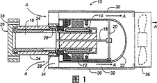
Fig. 1 is used for free-piston type stirling cooler cutaway view of the present invention.
Fig. 2 is the end-view of stirling cooler shown in Figure 1.
Fig. 3 is the sectional view that a signal, part disconnect, and has represented an issue embodiment of glass door merchandiser of the present invention.
Fig. 4 is the detailed section view of the part of being got of the line 4-4 along glass door merchandiser inferior segment shown in Figure 3.
Fig. 5 is mounted in the detailed top view of another issue embodiment of the heat exchanger assembly in the glass door merchandiser shown in Figure 3, and for the sake of clarity, cover is removed.
Fig. 6 is, along the detailed section view that the line 6-6 of heat exchanger assembly shown in Figure 5 is got, for the sake of clarity, cover is removed.
The specific embodiment
The present invention has utilized stirling cooler.Stirling cooler is known for the personnel that understand thoroughly this technology.Being used for stirling cooler of the present invention can buy from the Sunpower company of Ohio Athens.Be used for other stirling coolers of the present invention and be illustrated in U.S. Patent number 5,678,409; 5,647,217; 5,638,684; 5,596,875; 5,438,848 and 4,922,722, all introduce here as a reference.A kind of useful especially stirling cooler type is the free-piston type stirling cooler.Being used for a kind of free-piston type stirling cooler of the present invention can obtain from Global Cooling company.
With reference to accompanying drawing, identical part in all views of same reference numeral wherein, as can be seen, a free-piston type stirling cooler 10 (Fig. 1) comprises a linear electric motor 12, free-piston 14, displacer 16, displacer rod 18, displacer spring 20, inner casing 22, storage heater 24, heat absorption district or cold-zone 26 and heat extraction district or hot-zone 28.The function of these parts is known in the prior art, therefore is not described further here.
Stirling cooler 10 also comprises a cylindrical outer cover 30 that separates with inner casing 22, and has determined an annular space 32 therein.With many conduction vanes that from the hot-zone to the shell, radially extend outwardly 34 shell 30 is installed on the hot-zone 28 of stirling cooler 10.The Heat Conduction Material of blade 34 usefulness such as aluminium is made.Electric fan 36 installs to shell 30 other ends facing to blade 34.Electric fan 36 is designed to when it is worked air will flow into stirling cooler along arrow " A " direction, by 30 ends of the shell between the blade 34, flow out by space 32 and from the other end of shell.
The diameter of the cold-zone 26 of stirling cooler 10 is greater than storage heater 24.Four screws 38 that hold screw are located in the cold-zone.Screw 38 provides stirling cooler 10 has been installed to method on the equipment, as will be in following further discussion.
With reference to Fig. 3, a beverage bottle glass door merchandiser or GDM 40 have been represented.The district 42 of going up of GDM comprises a hot box, and case has heat insulation sidewall 44,46, heat insulation roof and diapire 48,50 respectively, and heat insulation rear wall 52.GDM40 also comprises an openable Qianmen 54, and it generally includes a window frame glass 56, the feasible article that can see from the outside among the GDM. Wall 44,46,48,50,52 and door 54 determined a heat-insulating room or hot box, wherein many beverage bottles 58 can be stored on the wire shelf 60,62 that are loaded in the case.
The inferior segment 60 of GDM40 comprises a not hot box, and case has sidewall 66,68, diapire 70 and front and rear wall 72,74 respectively. Wall 66,68,70,72,74 have determined not heat insulation chamber or case, as substrate of hot box and a mechanical box as stirling cooler 10 and relevant part and equipment.
Be not provided with stirling cooler 10 in the hot box.Though adopt single stirling cooler that the present invention is described, can specifically imagine and adopt more than one stirling cooler.
The diapire 50 of hot box has been determined a hole 76 (Fig. 4), and the cold-zone 26 of stirling cooler 10 extends through it.Be located on the hole 76 be one by the rectangular slab of making as the Heat Conduction Material of aluminium 78.The cold-zone 26 of stirling cooler 10 contacts with heat-conducting plate 78, makes heat can slave plate flow to the cold-zone of stirling cooler.In the junction of plate 78 and diapire 50,, a waterproof sealing agent (Fig. 3) as silicon edge circle 80 is arranged promptly around the periphery of plate.Silicon edge circle 80 prevents to obtain the fluid as condensed steam under plate 78.Plate 78 usefulness screw (not shown) install on the diapire 50.
The conduction vanes 82 of many rectangles installs on the plate 78, and slave plate protrudes upward.Blade 82 is made by the Heat Conduction Material as aluminium.Blade 82 mutual spaced at equal intervals and roughly being parallel to each other make air can freely flow (Fig. 4) between adjacent panels.Blade 82 installs to and makes on the plate 78 that heat can flow on the plate from blade.
Diapire 50 is provided with at an angle, and the front end of diapire is lower than the rear end of diapire slightly thus, makes the fluid as water that drops on the diapire flow downward at gravity effect lower edge diapire.In its minimum point, diapire 50 has been determined a discharge-channel 84, and it reaches outside the hot box (promptly reach hot box in) in hot box.Discharge-channel 84 is allowed as the fluid of water and thus from hot box have been removed water along diapire 50 passage of flowing through downwards.
Install on the discharge-channel 84 is a pipe 86 that stretches out downwards from passage.One as dish 88 fluid container are located at the bottom of the not hot box under the discharge-channel 84 on 70.The fluid that flows downward along discharge-channel 84 imports the dish 88 of collecting fluid by pipe 86.
A fan 90 is contained near on the diapire 50 of hot box back.The orientation of fan 90 makes it along the direction blow air shown in the arrow 92.A cover 94 is contained on the fan, and 82 is protruding and stretch on blade 82 from fan towards blade.Cover 94 aid in guide and passed through blade 82 by the air that fan 90 blows.
As preceding pointing out, stirling cooler 10 is located in the not hot box under the hot box diapire 50.Diapire 50 parts near stirling cooler 10 have been determined a recessed district 96.Recessed district 96 has been for air mobile between diapire 50 and stirling cooler 10 shells 30 provides more vacant place, allows that thus air more freely flows into annular spaces by blade 34 and flows out from fan 36.
The orientation of fan 36 makes it towards dish 88 blow air, shown in arrow 100.The heat heating that flow air is passed to blade from stirling cooler hot-zone 28 thereby passes to blade surrounding air between the blade 34 of stirling cooler 10.Heated air is blowed to dish 88 by fan 36.Therefore the evaporation that has promoted to coil fluid 88 by the hot-air that blows from fan 36.Window bar 102,104 is located at respectively in the front and rear wall 72,74, thereby allows the air not hot box of freely flowing through.
Four screws 106 of stirling cooler 10 usefulness install on the GDM 40, and four screws extend through the hole in the plate of aiming at four screws 38 in stirling cooler 10 cold-zones 26 78.Screw 106 can be screwed into hole 38, thus stirling cooler 10 is contained on the GDM 40.The soft foam thermal insulation barriers 108 of an annular press fit in the annular space between the columnar shaft of cylindrical hole 76 in the diapire 50 and storage heater 24.Thermal insulation barriers 108 prevents or has reduced the heat that hot box never passes to stirling cooler 10 cold-zones 26.
Consider the operation of GDM 40 now.Open door 54 and beverage bottle 58 is deposited on the shelf 60,62.Shelf 60,62 preferably tilt, if make that when shelf were taken a bottle away, gravity can move next beverage bottle to the position near door.Certainly, also can adopt horizontal shelf in the present invention.
Cooling usually will cause the condensate of water in air steam by the air that fan 90 is blown over blade 82 on the blade cold surface.When forming enough condensates on blade 82, it will flow to downwards on the plate 78 along blade.Because plate 78 at an angle, condensate will leave plate current to diapire 50.Because diapire 50 also at an angle, condensate will be towards the minimum point diffluence of wall.Because discharge-channel 84 is positioned at the minimum point of diapire 50, condensate will flow out hot box by discharge-channel.May on the hot box inwall, on the beverage bottle 58, on the wire shelf 60,62 or other condensates that on cover 94, form will similarly flow on the diapire 50, thereby flow out by discharge-channel 84.
The condensate of discharge-channel 84 of the flowing through pipe 86 of also will flowing through is fluid importing dish 88.Fluid from pipe 86 is collected in the dish 88.Blowed to fluid in the dish 88 by the air in 34 heating of stirling cooler 10 hot-zones 28 and blade and the space 32 between inner casing 22 and the shell 30 of flowing through by fan 36, promoted the evaporation of fluid in the dish.The wet air that produces by water evaporation in the dish 88 by the air band of window bar in the front and rear wall 72,74 102,104 circulation and leave not hot box in the surrounding environment of GDM 40.
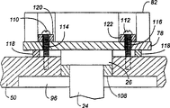
With reference to figure 5 and 6, can see, represented to be contained in the example of publicizing and implementing that a kind of confession of heat exchanger among the GDM 40 substitutes.The easiliest in Fig. 6 find out that heat exchange base plate 78 comprises many blades 82 that are contained on the base plate.Blade 82 is discontinuous at screw 110,112 and four screw 106 zones.Screw 110,112 extends through plate 78 mesopores 114,116, plate is contained on the diapire 50 of GDM40.A rectangular gasket 118 is located between the diapire 50 of plate 78 and GDM 40.Packing ring 118 is made as low hardness polyurethane by soft resilient material.Packing ring 118 is also as the seal between plate 78 and GDM 40 diapires 50, thereby no longer needs silicon edge circle 80.Each screw 110,112 also is provided with soft Elastic Circular annular pad 120,122, and is fitted between each head of screw bottom and plate 78 end faces.Packing ring 118 and pad 120,122 provide heat insulation between plate 78 and GDM 40 diapires 50, have reduced from stirling cooler 10 and have passed to plate 78, thereby passed to vibratory output on the diapire 50.The reduction of this vibratory output provides stirling cooler 10 more quiet conditions of work significantly.
When needs unload that stirling cooler 10 is repaired or when safeguarding from GDM 40, four screws 106 of removal.This allows that stirling cooler 10 skids off the hole 76 in the plate 78, unloads from GDM 40 fully.Then to stirling cooler 10 places under repair, perhaps slip back to cold-zone 26 in the hole 76 and again mounting screw 106 stirling cooler of a displacement is reinstalled among the GDM 40.The stirling cooler 10 that has unloaded is repaired in the place a long way off then.
Certainly should be understood that, more than only related to of the present invention some publicize and implement example, can carry out countless modifications and variations and not depart from the spirit and scope of the invention of setting in the claims.
Claims (14)
1. equipment (40) that adopts stirling cooler system comprising:
A hot box, above-mentioned case have an outside and an inboard, and above-mentioned case has been determined a discharge-channel (84) from above-mentioned inboard to the outside at least in part;
Stirling cooler (10) with a hot-zone (28) and cold-zone (26);
Above-mentioned stirling cooler (10) also comprises a fan (36), is used to the hot-zone (28) that makes air flow through above-mentioned stirling cooler (10),
A heat-conducting piece that is located in the above-mentioned case, above-mentioned heat-conducting piece is connected with the above-mentioned cold-zone (26) of above-mentioned stirling cooler (10) with heat exchange relationship, above-mentioned heat-conducting piece and above-mentioned discharge-channel (84) connect, and make that the condensate on above-mentioned heat-conducting piece can flow out above-mentioned hot box by above-mentioned discharge-channel (84); And
A fluid container (88) that is located under the above-mentioned discharge-channel (84), above-mentioned fluid container (88) connects with said fans (36), makes said fans (36) promote that fluid evaporates from above-mentioned fluid container (88).
2. equipment as claimed in claim 1 (40) is characterized in that: also comprise a pipeline (86) that connects with above-mentioned discharge-channel (84), be used for fluid is directed to above-mentioned fluid container (88) from above-mentioned discharge-channel (84).
3. equipment as claimed in claim 1 (40) is characterized in that: also comprise a fan (90), it is located in the above-mentioned hot box and makes air flow through above-mentioned heat-conducting piece.
4. equipment as claimed in claim 1 (40) is characterized in that: above-mentioned heat-conducting piece comprises many heat-conducting plates spaced apart from each other (82), and heat conduction each other concerns mutually.
5. equipment as claimed in claim 4 (40) is characterized in that: above-mentioned heat-conducting plate (82) installs on the heat-conducting block (78) that is located in the above-mentioned hot box, and the cold-zone (26) of above-mentioned stirling cooler (10) is connected on the above-mentioned heat-conducting block (78).
6. equipment as claimed in claim 1 (40), it is characterized in that: above-mentioned hot box comprises relative heat insulation sidewall (44,46), heat insulation roof and diapire (48,50), heat insulation rear wall (52) and the openable door (54) of having determined antetheca at least in part, above-mentioned diapire (50) has been determined above-mentioned discharge-channel (84) at least in part, and the shape of above-mentioned diapire (50) makes the fluid that drops on the above-mentioned diapire (50) be imported into above-mentioned discharge-channel (84);
Above-mentioned fluid container (88) is collected the fluid that flows out from above-mentioned discharge-channel (84);
Above-mentioned heat-conducting piece is arranged so that at the condensate on the above-mentioned heat-conducting piece and drops on the above-mentioned diapire (50); And
Said fans, (36) are towards above-mentioned fluid container (88).
7. equipment as claimed in claim 1 (40) is characterized in that: also comprise:
An elastic component (118) that is located between above-mentioned heat-conducting piece and the above-mentioned hot box makes that the vibration transmission from above-mentioned stirling cooler (10) to above-mentioned hot box is lowered.
8. equipment as claimed in claim 1 (40) is characterized in that: the orientation of said fans (36) is substantially perpendicular to above-mentioned fluid container (88), and said fans blows into air to fluid container (88).
9. equipment as claimed in claim 6 (40) is characterized in that: also comprise a fan (90) that connects with above-mentioned heat-conducting piece, said fans (90) makes air flow through above-mentioned heat-conducting piece.
10. equipment as claimed in claim 6 (40) is characterized in that: the orientation of said fans (36) is substantially perpendicular to above-mentioned fluid container (88), and said fans blows into air to fluid container (88).
11. equipment (40) as claim 1 or 6, it is characterized in that: above-mentioned stirling cooler (10) comprises one second heat-conducting piece (34), and above-mentioned second heat-conducting piece (34) is connected with the above-mentioned hot-zone (28) of above-mentioned stirling cooler (10) with heat exchange relationship.
12. the equipment (40) as claim 11 is characterized in that: said fans (36) is used to make air to flow through above-mentioned second heat-conducting piece (34).
13. the method for use such as the described equipment of claim 1-12 comprises:
Cooling is located at the heat-conducting piece in the hot box, above-mentioned heat-conducting piece connects with the cold-zone (26) of heat conduction relation and stirling cooler (10), the base area of above-mentioned hot box (50) has been determined a discharge-channel (84) at least in part, and the shape of above-mentioned base area (50) makes that the fluid that drops on the above-mentioned base area (50) is led in the above-mentioned discharge-channel (84);
Collection is flowed through in the fluid collector (88) of fluid outside the above-mentioned hot box of above-mentioned discharge-channel (84); And
Make air flow through above-mentioned fluid collector (88) and promote the evaporation of fluid from gatherer.
14. method as claimed in claim 13 is characterized in that: make air flow through a heat-conducting piece that is located in the hot box.
Applications Claiming Priority (2)
| Application Number | Priority Date | Filing Date | Title |
|---|---|---|---|
| US09/412,687 | 1999-10-05 | ||
| US09/412,687 US6266963B1 (en) | 1999-10-05 | 1999-10-05 | Apparatus using stirling cooler system and methods of use |
Publications (2)
| Publication Number | Publication Date |
|---|---|
| CN1377456A CN1377456A (en) | 2002-10-30 |
| CN100467985C true CN100467985C (en) | 2009-03-11 |
Family
ID=23634032
Family Applications (1)
| Application Number | Title | Priority Date | Filing Date |
|---|---|---|---|
| CNB008138699A Expired - Fee Related CN100467985C (en) | 1999-10-05 | 2000-09-22 | Apparatus using stirling cooler system and methods of use |
Country Status (12)
| Country | Link |
|---|---|
| US (2) | US6266963B1 (en) |
| EP (1) | EP1218677B1 (en) |
| JP (1) | JP2003511647A (en) |
| CN (1) | CN100467985C (en) |
| AT (1) | ATE297000T1 (en) |
| AU (1) | AU7602000A (en) |
| BR (1) | BR0014466A (en) |
| DE (1) | DE60020581T2 (en) |
| ES (1) | ES2239617T3 (en) |
| TR (1) | TR200200917T2 (en) |
| TW (1) | TW496946B (en) |
| WO (1) | WO2001025702A1 (en) |
Families Citing this family (31)
| Publication number | Priority date | Publication date | Assignee | Title |
|---|---|---|---|---|
| US6532749B2 (en) * | 1999-09-22 | 2003-03-18 | The Coca-Cola Company | Stirling-based heating and cooling device |
| US6550269B2 (en) * | 2000-02-16 | 2003-04-22 | The Coca-Cola Company | Dispensing apparatus with directional LED lighting |
| WO2001084065A1 (en) * | 2000-04-27 | 2001-11-08 | Sharp Kabushiki Kaisha | Cold insulating chamber |
| US6557366B1 (en) * | 2001-08-14 | 2003-05-06 | Donatos Pizzeria Corporation | Apparatus for cold-holding food products |
| US6854275B2 (en) * | 2002-08-08 | 2005-02-15 | International Business Machines Corporation | Method for cooling automated storage library media using thermoelectric cooler |
| US6751963B2 (en) * | 2002-09-24 | 2004-06-22 | The Coleman Company, Inc. | Portable insulated container with refrigeration |
| US7401472B2 (en) * | 2003-01-17 | 2008-07-22 | Tecumseh Products Company | Modular heating or cooling system |
| US20050097911A1 (en) * | 2003-11-06 | 2005-05-12 | Schlumberger Technology Corporation | [downhole tools with a stirling cooler system] |
| US7913498B2 (en) * | 2003-11-06 | 2011-03-29 | Schlumberger Technology Corporation | Electrical submersible pumping systems having stirling coolers |
| JP4189855B2 (en) * | 2003-12-03 | 2008-12-03 | ツインバード工業株式会社 | Fin structure |
| US20050166601A1 (en) * | 2004-02-03 | 2005-08-04 | The Coleman Company, Inc. | Portable insulated container incorporating stirling cooler refrigeration |
| US7032400B2 (en) * | 2004-03-29 | 2006-04-25 | Hussmann Corporation | Refrigeration unit having a linear compressor |
| EP1630492A3 (en) * | 2004-08-23 | 2008-10-29 | Twinbird Corporation | Temperature controlling unit and container using the same |
| US7650757B2 (en) * | 2005-01-24 | 2010-01-26 | Delphi Technologies, Inc. | Thermoelectric heat transfer system |
| US7263856B2 (en) * | 2005-05-26 | 2007-09-04 | Lg Electronics Inc. | Refrigerator |
| CA2618570A1 (en) * | 2005-08-12 | 2007-02-22 | Carrier Corporation | A thermo-electric defrosting system |
| JP2007085635A (en) * | 2005-09-21 | 2007-04-05 | Twinbird Corp | Liquid cooling device |
| US20070266714A1 (en) * | 2006-05-19 | 2007-11-22 | Andreas Fiedler | Heat exchanger assembly |
| JP2008025888A (en) * | 2006-07-19 | 2008-02-07 | Sanyo Electric Co Ltd | Low-temperature showcase |
| WO2008109696A1 (en) * | 2007-03-05 | 2008-09-12 | Nanopore, Inc. | Method and apparatus for cooling a container |
| US20090211285A1 (en) * | 2008-02-26 | 2009-08-27 | Picker Benjamin P | Condensing Unit |
| CA2629493A1 (en) * | 2008-04-18 | 2009-10-18 | Mabe Canada Inc. | Clothes dryer with louvre cover |
| US8793992B2 (en) * | 2008-07-28 | 2014-08-05 | Spansion Llc | Thermoelectric device for use with Stirling engine |
| US20110239677A1 (en) * | 2010-04-01 | 2011-10-06 | The Coca-Cola Company | Chest Cooler |
| US8925338B2 (en) * | 2010-04-01 | 2015-01-06 | The Coca-Cola Company | Chest cooler |
| US20110304105A1 (en) * | 2010-06-14 | 2011-12-15 | Li-Cor, Inc. | Diffusion and sorption free gaskets for gas exchange measurement systems |
| KR102095739B1 (en) * | 2013-04-24 | 2020-04-01 | 지멘스 헬스케어 리미티드 | An assembly comprising a two-stage cryogenic refrigerator and associated mounting arrangement |
| EP3102897B1 (en) * | 2014-01-31 | 2021-09-15 | The Coca-Cola Company | Systems and methods for vacuum cooling a beverage |
| EP2980511A1 (en) * | 2014-08-01 | 2016-02-03 | Werner W. Lorke | Cooling devices, cooling modules and cooling fin modules and use of the same |
| CN104848625A (en) * | 2015-05-12 | 2015-08-19 | 宁波荣捷特机械制造有限公司 | Quick refrigerating system |
| US20170335794A1 (en) * | 2016-05-20 | 2017-11-23 | Beyond Zero, Inc. | Ice storage unit |
Citations (1)
| Publication number | Priority date | Publication date | Assignee | Title |
|---|---|---|---|---|
| CH233266A (en) * | 1941-08-16 | 1944-07-15 | Hermes Patentverwertungs Gmbh | Refrigerator with compression refrigeration system. |
Family Cites Families (118)
| Publication number | Priority date | Publication date | Assignee | Title |
|---|---|---|---|---|
| US1815170A (en) | 1928-03-24 | 1931-07-21 | Frigidaire Corp | Refrigerating apparatus |
| US2095008A (en) | 1932-04-15 | 1937-10-05 | Nash Kelvinator Corp | Refrigerating apparatus |
| US2342299A (en) | 1940-07-26 | 1944-02-22 | Novadel Agene Corp | Brew cooling and dispensing installation |
| US2470547A (en) | 1945-06-30 | 1949-05-17 | Vendorlator Mfg Company | Refrigerator having condensate disposal means |
| US2512545A (en) | 1948-06-11 | 1950-06-20 | Frederick E Hazard | Structure for and method of transfer, exchange, control regulation, and storage of heat and cold |
| US2660037A (en) | 1950-11-13 | 1953-11-24 | Amana Refrigeration Inc | Refrigerator construction |
| US2672029A (en) | 1952-03-18 | 1954-03-16 | Gen Motors Corp | Removable unit in refrigerating apparatus |
| US2961082A (en) | 1956-07-09 | 1960-11-22 | Vendo Co | Coin-operated electrically-controlled cup dispensing machine |
| US2885142A (en) | 1956-07-09 | 1959-05-05 | Westinghouse Electric Corp | Air conditioning apparatus |
| US3004408A (en) | 1957-09-25 | 1961-10-17 | Philips Corp | Cold installation designed more particularly for storage of ampullae |
| US3206943A (en) | 1962-02-09 | 1965-09-21 | Borg Warner | Refrigerator having a movable refrigeration unit therein |
| US3230733A (en) | 1962-04-10 | 1966-01-25 | Emhart Corp | Refrigeration system and elements thereof |
| US3302429A (en) | 1965-09-20 | 1967-02-07 | Hughes Aircraft Co | Thermal transfer arrangement for cryogenic device cooling and method of operation |
| US3712078A (en) | 1971-11-22 | 1973-01-23 | Krispin Eng Ltd | Refrigeration unit |
| US3853437A (en) | 1973-10-18 | 1974-12-10 | Us Army | Split cycle cryogenic cooler with rotary compressor |
| US4037650A (en) | 1975-05-23 | 1977-07-26 | National Research Development Corporation | Thermal storage apparatus |
| US3997028A (en) | 1975-06-23 | 1976-12-14 | Lawrence Peska Associates, Inc. | Entertainment table |
| US4037081A (en) | 1976-06-21 | 1977-07-19 | Aldridge Bobby V | Electro-lunch bucket |
| US4138855A (en) | 1976-06-25 | 1979-02-13 | Exxon Research & Engineering Co. | Transferring heat from relatively cold to relatively hot locations |
| US4176526A (en) | 1977-05-24 | 1979-12-04 | Polycold Systems, Inc. | Refrigeration system having quick defrost and re-cool |
| CH627260A5 (en) | 1977-09-07 | 1981-12-31 | Sibir Kuehlapparate | |
| CA1108499A (en) | 1979-03-15 | 1981-09-08 | Canadian Gas Research Institute | Two-stage heat exchanger |
| US4471633A (en) | 1979-06-05 | 1984-09-18 | Copeland Corporation | Condensing unit |
| US4259844A (en) | 1979-07-30 | 1981-04-07 | Helix Technology Corporation | Stacked disc heat exchanger for refrigerator cold finger |
| US4306613A (en) | 1980-03-10 | 1981-12-22 | Christopher Nicholas S | Passive cooling system |
| FR2486638B1 (en) | 1980-07-11 | 1986-03-28 | Thomson Brandt | REFRIGERATION UNIT WITH DIFFERENT TEMPERATURE COMPARTMENTS |
| US4363217A (en) * | 1981-01-29 | 1982-12-14 | Venuti Guy S | Vibration damping apparatus |
| DE3171800D1 (en) | 1981-05-28 | 1985-09-19 | Fuji Electric Co Ltd | Water-cooled heat-accumulating type drink cooling system |
| US4377074A (en) | 1981-06-29 | 1983-03-22 | Kaman Sciences Corporation | Economizer refrigeration cycle space heating and cooling system and process |
| US4416122A (en) | 1982-05-03 | 1983-11-22 | Tannetics, Inc. | Unitary removable refrigeration system and cooler |
| IL67440A (en) | 1982-12-09 | 1988-08-31 | Israel State | Compressor unit for split cycle cryogenic coolers |
| US4480445A (en) | 1983-01-21 | 1984-11-06 | Vladimir Goldstein | Thermal storage heat exchanger systems of heat pumps |
| US4554797A (en) | 1983-01-21 | 1985-11-26 | Vladimir Goldstein | Thermal storage heat exchanger systems of heat pumps |
| DE3318448A1 (en) | 1983-05-20 | 1984-11-22 | Licentia Patent-Verwaltungs-Gmbh, 6000 Frankfurt | METHOD AND WORK EQUIPMENT FOR INSTALLING A MOTOR COMPRESSOR IN A NICHE OF A REFRIGERATOR |
| US4490991A (en) | 1983-12-29 | 1985-01-01 | General Electric Company | High-side refrigeration system assembly adapted to be mounted in a refrigerator machinery compartment |
| US4694650A (en) | 1986-07-28 | 1987-09-22 | Mechanical Technology Incorporated | Externally tuned vibration absorber |
| US4783968A (en) | 1986-08-08 | 1988-11-15 | Helix Technology Corporation | Vibration isolation system for a linear reciprocating machine |
| FR2609789B1 (en) | 1987-01-15 | 1989-05-12 | Cappa Robert | METHOD AND DEVICE FOR MONITORING THE PROPER OPERATION OF A COLD PRODUCTION INSTALLATION |
| US4726193C2 (en) | 1987-02-13 | 2001-03-27 | Marlow Ind Inc | Temperature controlled picnic box |
| JPS63263250A (en) | 1987-04-20 | 1988-10-31 | Mitsubishi Electric Corp | Vibration reducing device for stirling engine |
| US4759190A (en) | 1987-04-22 | 1988-07-26 | Leonard Trachtenberg | Vehicle thermoelectric cooling and heating food and drink appliance |
| US4823554A (en) | 1987-04-22 | 1989-04-25 | Leonard Trachtenberg | Vehicle thermoelectric cooling and heating food and drink appliance |
| JPS6436468A (en) | 1987-07-31 | 1989-02-07 | Toshiba Corp | Thermal head |
| US4843826A (en) | 1987-10-09 | 1989-07-04 | Cryodynamics, Inc. | Vehicle air conditioner |
| US4827733A (en) | 1987-10-20 | 1989-05-09 | Dinh Company Inc. | Indirect evaporative cooling system |
| DE3735551C1 (en) * | 1987-10-21 | 1988-12-15 | Loh Kg Rittal Werk | Device for removing condensation from a compressor-operated cooling device |
| US4831831A (en) | 1988-02-16 | 1989-05-23 | Baltimore Aircoil Company, Inc. | Thermal storage unit with coil extension during melt |
| JPH01145614U (en) * | 1988-03-17 | 1989-10-06 | ||
| JPH01250026A (en) * | 1988-03-30 | 1989-10-05 | Mitsubishi Electric Corp | Infrared detecting device |
| US4827735A (en) | 1988-04-07 | 1989-05-09 | Off-Peak Devices, Inc. | Off peak storage device |
| JP2552709B2 (en) | 1988-05-24 | 1996-11-13 | 三菱電機株式会社 | refrigerator |
| JPH02217758A (en) | 1989-02-16 | 1990-08-30 | Mitsubishi Electric Corp | Control device for refrigeratin machine |
| US4941527A (en) | 1989-04-26 | 1990-07-17 | Thermacore, Inc. | Heat pipe with temperature gradient |
| US4964279A (en) | 1989-06-07 | 1990-10-23 | Baltimore Aircoil Company | Cooling system with supplemental thermal storage |
| JP2714155B2 (en) * | 1989-06-30 | 1998-02-16 | 株式会社東芝 | Cooling room |
| EP0409179B1 (en) | 1989-07-19 | 1995-01-18 | Showa Aluminum Corporation | Heat pipe |
| US4996841A (en) | 1989-08-02 | 1991-03-05 | Stirling Thermal Motors, Inc. | Stirling cycle heat pump for heating and/or cooling systems |
| US4949554A (en) | 1989-09-08 | 1990-08-21 | Specialty Equipment Companies, Inc. | Single pane, curved glass lid, frozen food merchandiser |
| US5142872A (en) | 1990-04-26 | 1992-09-01 | Forma Scientific, Inc. | Laboratory freezer appliance |
| US4977754A (en) | 1990-05-01 | 1990-12-18 | Specialty Equipment Companies, Inc. | Next-to-be-purchased cold beverage merchandiser |
| US5094083A (en) | 1990-08-14 | 1992-03-10 | Horn Stuart B | Stirling cycle air conditioning system |
| US5069273A (en) | 1990-10-12 | 1991-12-03 | Duke Manufacturing Co. | Food server |
| US5259214A (en) | 1990-11-08 | 1993-11-09 | Mitsubishi Denki Kabushiki Kaisha | Air conditioning system |
| KR940011324B1 (en) | 1991-10-10 | 1994-12-05 | 주식회사 금성사 | Stiling cycle |
| DE4201755A1 (en) * | 1992-01-23 | 1993-07-29 | Leybold Ag | Cryopump with an essentially pot-shaped housing |
| US5228299A (en) * | 1992-04-16 | 1993-07-20 | Helix Technology Corporation | Cryopump water drain |
| US5347827A (en) | 1992-07-01 | 1994-09-20 | The Coca-Cola Company | Modular refrigeration apparatus |
| US5303769A (en) | 1992-09-25 | 1994-04-19 | The M. W. Kellogg Company | Integrated thermosiphon heat exchanger apparatus |
| US5311927A (en) | 1992-11-27 | 1994-05-17 | Thermo King Corporation | Air conditioning and refrigeration apparatus utilizing a cryogen |
| US5305825A (en) | 1992-11-27 | 1994-04-26 | Thermo King Corporation | Air conditioning and refrigeration apparatus utilizing a cryogen |
| US5259198A (en) | 1992-11-27 | 1993-11-09 | Thermo King Corporation | Air conditioning and refrigeration systems utilizing a cryogen |
| US5309986A (en) | 1992-11-30 | 1994-05-10 | Satomi Itoh | Heat pipe |
| KR950008382B1 (en) | 1992-12-17 | 1995-07-28 | 엘지전자주식회사 | Refregerator using stiring cycle |
| US5333460A (en) | 1992-12-21 | 1994-08-02 | Carrier Corporation | Compact and serviceable packaging of a self-contained cryocooler system |
| US5342176A (en) | 1993-04-05 | 1994-08-30 | Sunpower, Inc. | Method and apparatus for measuring piston position in a free piston compressor |
| US5440894A (en) | 1993-05-05 | 1995-08-15 | Hussmann Corporation | Strategic modular commercial refrigeration |
| US5341653A (en) * | 1993-11-03 | 1994-08-30 | Tippmann Joseph R | Apparatus and method for disposing of condensate from evaporator drip pans |
| US5406805A (en) | 1993-11-12 | 1995-04-18 | University Of Maryland | Tandem refrigeration system |
| JPH07180921A (en) | 1993-12-24 | 1995-07-18 | Toshiba Corp | Stirling cold storage box |
| US5493874A (en) | 1994-03-10 | 1996-02-27 | Landgrebe; Mark A. | Compartmented heating and cooling chest |
| US5525845A (en) | 1994-03-21 | 1996-06-11 | Sunpower, Inc. | Fluid bearing with compliant linkage for centering reciprocating bodies |
| US5537820A (en) | 1994-06-27 | 1996-07-23 | Sunpower, Inc. | Free piston end position limiter |
| US5524453A (en) | 1994-08-01 | 1996-06-11 | James; Timothy W. | Thermal energy storage apparatus for chilled water air-conditioning systems |
| US5551250A (en) | 1994-09-08 | 1996-09-03 | Traulsen & Co. Inc. | Freezer evaporator defrost system |
| US5649431A (en) | 1994-11-15 | 1997-07-22 | Tdindustries, Inc. | Thermal storage cooling system |
| DE19501035A1 (en) | 1995-01-16 | 1996-07-18 | Bayer Ag | Stirling engine with heat transfer injection |
| US5906290A (en) | 1996-01-29 | 1999-05-25 | Haberkorn; Robert W. | Insulated container |
| JP2710023B2 (en) * | 1995-04-13 | 1998-02-10 | 株式会社ユピテック | Electronic cooling device |
| DE19516499A1 (en) | 1995-05-05 | 1996-12-05 | Bosch Gmbh Robert | Processes for exhaust gas heat use in heating and cooling machines |
| US5645407A (en) | 1995-05-25 | 1997-07-08 | Mechanical Technology Inc. | Balanced single stage linear diaphragm compressor |
| US5647225A (en) | 1995-06-14 | 1997-07-15 | Fischer; Harry C. | Multi-mode high efficiency air conditioning system |
| US5596875A (en) | 1995-08-10 | 1997-01-28 | Hughes Aircraft Co | Split stirling cycle cryogenic cooler with spring-assisted expander |
| US5642622A (en) | 1995-08-17 | 1997-07-01 | Sunpower, Inc. | Refrigerator with interior mounted heat pump |
| US5678421A (en) | 1995-12-26 | 1997-10-21 | Habco Beverage Systems Inc. | Refrigeration unit for cold space merchandiser |
| US5737923A (en) | 1995-10-17 | 1998-04-14 | Marlow Industries, Inc. | Thermoelectric device with evaporating/condensing heat exchanger |
| KR970047662A (en) | 1995-12-29 | 1997-07-26 | 구자홍 | Refrigerator with Warm Room |
| US5647217A (en) | 1996-01-11 | 1997-07-15 | Stirling Technology Company | Stirling cycle cryogenic cooler |
| US5655376A (en) | 1996-01-22 | 1997-08-12 | Hughes Electronics | Combination coolant pump/dynamic balancer for stirling refrigerators |
| US5735131A (en) | 1996-03-26 | 1998-04-07 | Lambright, Jr.; Harley | Supplemental refrigerated element |
| NZ286458A (en) | 1996-04-26 | 1999-01-28 | Fisher & Paykel | Evaporation tray to catch defrost water from refrigerator, bottom consists of flexible membrane |
| US5678409A (en) | 1996-06-21 | 1997-10-21 | Hughes Electronics | Passive three state electromagnetic motor/damper for controlling stirling refrigerator expanders |
| US5920133A (en) | 1996-08-29 | 1999-07-06 | Stirling Technology Company | Flexure bearing support assemblies, with particular application to stirling machines |
| US5895033A (en) | 1996-11-13 | 1999-04-20 | Stirling Technology Company | Passive balance system for machines |
| JPH10148411A (en) | 1996-11-15 | 1998-06-02 | Sanyo Electric Co Ltd | Stirling refrigerating system |
| US6023937A (en) | 1996-12-11 | 2000-02-15 | Carrier Corporation | Compressor mounting arrangement |
| US5724833A (en) | 1996-12-12 | 1998-03-10 | Phillips Petroleum Company | Control scheme for cryogenic condensation |
| US6079481A (en) | 1997-01-23 | 2000-06-27 | Ail Research, Inc | Thermal storage system |
| JP2978451B2 (en) * | 1997-04-11 | 1999-11-15 | ジーエーシー株式会社 | Refrigeration equipment |
| WO1998034076A1 (en) | 1997-01-31 | 1998-08-06 | Gac Corporation | Cold storage apparatus |
| KR100233198B1 (en) | 1997-07-04 | 1999-12-01 | 윤종용 | Pumping apparatus for stirring refrigerrator |
| US5878581A (en) | 1997-10-27 | 1999-03-09 | Advanced Metallurgy Incorporated | Closed multi-loop water-to-water heat exchanger system and method |
| TW426798B (en) | 1998-02-06 | 2001-03-21 | Sanyo Electric Co | Stirling apparatus |
| US6178770B1 (en) | 1998-10-22 | 2001-01-30 | Evapco International, Inc. | Ice-on-coil thermal storage apparatus and method |
| US6112526A (en) | 1998-12-21 | 2000-09-05 | Superconductor Technologies, Inc. | Tower mountable cryocooler and HTSC filter system |
| US6158499A (en) | 1998-12-23 | 2000-12-12 | Fafco, Inc. | Method and apparatus for thermal energy storage |
| US6148634A (en) | 1999-04-26 | 2000-11-21 | 3M Innovative Properties Company | Multistage rapid product refrigeration apparatus and method |
| US6067804A (en) | 1999-08-06 | 2000-05-30 | American Standard Inc. | Thermosiphonic oil cooler for refrigeration chiller |
| US6073547A (en) | 1999-09-13 | 2000-06-13 | Standex International Corporation | Food temperature maintenance apparatus |
-
1999
- 1999-10-05 US US09/412,687 patent/US6266963B1/en not_active Expired - Lifetime
-
2000
- 2000-09-22 TR TR2002/00917T patent/TR200200917T2/en unknown
- 2000-09-22 JP JP2001528402A patent/JP2003511647A/en active Pending
- 2000-09-22 ES ES00965282T patent/ES2239617T3/en not_active Expired - Lifetime
- 2000-09-22 AU AU76020/00A patent/AU7602000A/en not_active Abandoned
- 2000-09-22 WO PCT/US2000/025973 patent/WO2001025702A1/en active IP Right Grant
- 2000-09-22 DE DE60020581T patent/DE60020581T2/en not_active Expired - Lifetime
- 2000-09-22 AT AT00965282T patent/ATE297000T1/en not_active IP Right Cessation
- 2000-09-22 EP EP00965282A patent/EP1218677B1/en not_active Expired - Lifetime
- 2000-09-22 CN CNB008138699A patent/CN100467985C/en not_active Expired - Fee Related
- 2000-09-22 BR BR0014466-5A patent/BR0014466A/en not_active IP Right Cessation
- 2000-10-05 TW TW089120800A patent/TW496946B/en active
-
2001
- 2001-03-21 US US09/813,627 patent/US6675588B2/en not_active Expired - Fee Related
Patent Citations (1)
| Publication number | Priority date | Publication date | Assignee | Title |
|---|---|---|---|---|
| CH233266A (en) * | 1941-08-16 | 1944-07-15 | Hermes Patentverwertungs Gmbh | Refrigerator with compression refrigeration system. |
Also Published As
| Publication number | Publication date |
|---|---|
| US6266963B1 (en) | 2001-07-31 |
| BR0014466A (en) | 2002-06-11 |
| US20010011459A1 (en) | 2001-08-09 |
| WO2001025702A1 (en) | 2001-04-12 |
| DE60020581T2 (en) | 2006-04-27 |
| CN1377456A (en) | 2002-10-30 |
| JP2003511647A (en) | 2003-03-25 |
| TR200200917T2 (en) | 2002-06-21 |
| TW496946B (en) | 2002-08-01 |
| ATE297000T1 (en) | 2005-06-15 |
| EP1218677A1 (en) | 2002-07-03 |
| DE60020581D1 (en) | 2005-07-07 |
| ES2239617T3 (en) | 2005-10-01 |
| AU7602000A (en) | 2001-05-10 |
| US6675588B2 (en) | 2004-01-13 |
| EP1218677B1 (en) | 2005-06-01 |
Similar Documents
| Publication | Publication Date | Title |
|---|---|---|
| CN100467985C (en) | Apparatus using stirling cooler system and methods of use | |
| US6550255B2 (en) | Stirling refrigeration system with a thermosiphon heat exchanger | |
| CN1246654C (en) | Merchandiser with slide-out stirling regeneration module | |
| CN204594038U (en) | A kind of central refrigerating module of wind cooling refrigerator | |
| CN1985136A (en) | Cooling chamber and its operation method | |
| US20020134090A1 (en) | Stirling-based heating and cooling device | |
| CN201187915Y (en) | Movable refrigerator for industry | |
| RU2330222C1 (en) | Electro refrigirator with hot meal thermos of nr yansufin | |
| CN210772989U (en) | Integral refrigerating unit for vending machine | |
| US20110042054A1 (en) | Hot and cold storage | |
| CN114147516A (en) | Cascade type refrigeration and freezing clamping device | |
| SU1211546A1 (en) | Domestic refrigerator | |
| Gedik et al. | Experimental investigation of a household refrigerator performance using chimney-type condenser | |
| KR100406047B1 (en) | Condenser cooling device using condensing water of air-conditioner | |
| JP2017201222A (en) | Liquid refrigerator | |
| JPH10292927A (en) | Method and structure for discharging drain at refrigerating cycle | |
| KR0156719B1 (en) | Heat exchanger apparatus of a refrigerator | |
| WO2001006185A1 (en) | An evaporator unit | |
| KR20000008803U (en) | Evaporator Name of Refrigerator | |
| RU96101043A (en) | Multipurpose refrigerating plant | |
| KR0125547Y1 (en) | Cover structure of machine room of a refrigerator | |
| CN1536301A (en) | Two-way air-supplying device of bottom freezing type refrigerator | |
| AU5796000A (en) | An evaporator unit | |
| KR20000038050A (en) | Structure of mechanical chamber of showcase for evaporating defrost water | |
| JPH058368U (en) | Chow case with built-in condensing unit |
Legal Events
| Date | Code | Title | Description |
|---|---|---|---|
| C06 | Publication | ||
| PB01 | Publication | ||
| C10 | Entry into substantive examination | ||
| SE01 | Entry into force of request for substantive examination | ||
| C14 | Grant of patent or utility model | ||
| GR01 | Patent grant | ||
| C17 | Cessation of patent right | ||
| CF01 | Termination of patent right due to non-payment of annual fee |
Granted publication date: 20090311 Termination date: 20130922 |