CN100504462C - Reflective polarizer containing polymer fibers - Google Patents
Reflective polarizer containing polymer fibers Download PDFInfo
- Publication number
- CN100504462C CN100504462C CNB2006800063733A CN200680006373A CN100504462C CN 100504462 C CN100504462 C CN 100504462C CN B2006800063733 A CNB2006800063733 A CN B2006800063733A CN 200680006373 A CN200680006373 A CN 200680006373A CN 100504462 C CN100504462 C CN 100504462C
- Authority
- CN
- China
- Prior art keywords
- fiber
- polymer
- scattering
- light
- along
- Prior art date
- Legal status (The legal status is an assumption and is not a legal conclusion. Google has not performed a legal analysis and makes no representation as to the accuracy of the status listed.)
- Expired - Fee Related
Links
Images


Classifications
-
- G—PHYSICS
- G02—OPTICS
- G02B—OPTICAL ELEMENTS, SYSTEMS OR APPARATUS
- G02B5/00—Optical elements other than lenses
- G02B5/30—Polarising elements
-
- G—PHYSICS
- G02—OPTICS
- G02B—OPTICAL ELEMENTS, SYSTEMS OR APPARATUS
- G02B5/00—Optical elements other than lenses
- G02B5/30—Polarising elements
- G02B5/3008—Polarising elements comprising dielectric particles, e.g. birefringent crystals embedded in a matrix
Abstract
A polarizer is formed with an arrangement of polymer fibers substantially parallel within a polymer matrix. The polymer fibers are formed of at least first and second polymer materials. At least one of the polymer matrix and the first and second polymer materials is birefringent, and provides a birefringent interface with the adjacent material. Light is reflected and/or scattered at the birefringent interfaces with sensitivity to the polarization of the light. In some embodiments, the polymer fibers are formed as composite fibers, having a plurality of scattering polymer fibers disposed within a filler to form the composite fiber. In other embodiments, the polymer fiber is a multilayered polymer fiber. The polymer fibers may be arranged within the polymer matrix as part of a fiber weave.
Description
Technical field
The present invention relates to polymeric optical films, more particularly, relate to the reflective polarizing polymeric optical films that comprises polymer fiber.
Background technology
Unpolarized light wave vibrates around beam axis on a large amount of planes.If only a plane internal vibration, this light is called as linearly polarized light to light wave.Adopt polarized light can realize a plurality of useful optical systems.For example, with polarized light the electro-optical device such as LCD etc. is thrown light on and adopt crossed polarizers to combine with addressable sandwiching liquid crystal to be provided as the basis that picture shows.In photography, that has adopted that polarizing filter reduces that direct reflection causes dazzles light and brightness.Polarizing filter, circular polarizing disk and other optical element also can be used to reduce the light of dazzling on the display screen.
Can adopt multiple different types of polarizing coating that nonpolarized light is risen partially.Absorb (dichroic type) polarizer and have the polarization dependent absorption body (be generally and contain the iodine chain) that is arranged in the polymer substrate as the alloy phase.This film absorbs its electric field intensity polarized light parallel with absorber and sees through its electric field intensity polarized light vertical with absorber.The optical characteristics of this film is generally minute surface, does not almost pass the diffuse transmission of this film, does not also almost have the diffuse reflection from this film surface.
Another kind of polarizing coating is a reflective polarizer, thus the light of a polarization state of its transmission and the light that reflects another polarization state is isolated the light that is in different polarization states.A kind of reflective polarizer is multi-layer optical film (MOF), and this film is to be formed by stacking of multilayer alternating polymer material.A kind of material is optically isotropic and another kind of for birefringent, and one of refractive index of birefringent material is complementary with the refractive index of isotropic material.Its in wide wavelength coverage (for example in visible-range) can make each the layer thickness difference in stacking, so that can be used as the quarter-wave lamella.The incident light that is in a kind of polarization state sees through polarizer in the specular transmission mode substantially owing to the refractive index of coupling.Yet, be in the incident light of another polarization state, on the interface between the different retes, the repeatedly relevant or incoherent reflecting of experience and by polarizer reflection.Because the alternating polymer layer is the plane substantially, so the reflection ray major part is a direct reflection.
Another kind of reflective polarizing film constitutes by being scattered in the intramatrical alloy of external phase.With respect to the width and the height of film, alloy is less.Can utilize the characteristic of these alloys to make film have multiple reflection and transmission performance.This alloy constitutes the intramatrical dispersed polymeres phase of external phase.Can change the size and the arrangement of alloy by stretched film.One of external phase and disperse phase are birefringent, and one of refractive index of birefringent material is complementary with optically isotropic another refractive index mutually.Select external phase and the material of disperse phase and the mismatch degree that level of stretch can influence birefraction between disperse phase and the external phase.Other adjustable characteristic comprises size, alloy shape and the alloy volume fill factor, curve factor of adjusting alloy in the film according to wavelength.In these systems, the polarized light that experiences refractive index mismatch between disperse phase and the external phase is by diffuse reflection, and crossed polarized light is by specular transmission.
Summary of the invention
A specific embodiments of the present invention relates to optical body, and it comprises that polymer substrate and Duo Gen place the polymer fiber in the polymer substrate.At least one in the described polymer fiber comprises a plurality of catoptrical birefringence interfaces that are used for.The birefringence interface is formed between first polymeric material and second polymeric material, and at least one of described first polymeric material and described second polymeric material is birefringence.Extend in described polymer fiber and along the axle of described polymer fiber at described birefringence interface.The orientation of described polymer fiber is basically parallel to first.The light that is parallel to described first polarization be different from described birefringence refringence at the interface be parallel to second polarization light in described birefringence refringence at the interface, described second with described first quadrature.
Another embodiment of the invention relates to optical body, and described optical body comprises such optical material, and this optical material has first refractive index n along first
x, along having second refractive index n perpendicular to described first second
yThe polymer fiber that extends is parallel to described first and places in the described optical material.Described polymer fiber comprises first birefringent material, and it is along described first extension, and has first refractive index n along described first
1x, have second refractive index n along described second
1y, n wherein
1xBe different from n
1yThe polymer fiber of described extension comprises second birefringent material, and it is along described first extension, and has first refractive index n along described first
2x, have second refractive index n along described second
2yDescribed optical body to along the incident scattering of light of described first polarization with different to incident scattering of light along described second polarization.
Another embodiment of the invention relates to optical body, and this optical body comprises polymer substrate and places many interior polymer fibers of described polymer substrate.In the described polymer fiber at least one comprises the birefringence scattering device of a plurality of extensions to be used for scatter incident light, and described scattering device is placed in described polymer fiber inside.
Above summary of the invention is not intended to describe embodiment or each embodiment shown in each of the present invention.Following accompanying drawing and detailed Description Of The Invention more detailed example go out these embodiments.
Description of drawings
Can more fully understand the present invention to the detailed description of a plurality of embodiments of the present invention below considering in conjunction with the accompanying drawings, wherein:
Figure 1A and Figure 1B schematically show the polarizer that has direct reflection and diffusing characteristic diffuser respectively.
Fig. 2 schematically shows the part excision view of polarizer embodiment in accordance with the principles of the present invention.
Fig. 3 A-Fig. 3 D schematically shows the cut-open view of optical element embodiment in accordance with the principles of the present invention.
Fig. 3 E schematically shows in accordance with the principles of the present invention the wherein incomplete parallel optical element embodiment of polymer fiber.
Fig. 3 F-Fig. 3 H schematically shows the cut-open view of optical element embodiment in accordance with the principles of the present invention.
Fig. 3 I-Fig. 3 M schematically shows the cut-open view of the optical element embodiment that has patterned surface in accordance with the principles of the present invention.
Fig. 4 A-Fig. 4 C schematically shows the cut-open view of multi-layer fiber in accordance with the principles of the present invention.
Fig. 4 D-Fig. 4 G schematically shows the cut-open view of the polarizer that adopts multi-layer fiber in accordance with the principles of the present invention.
Fig. 5 A-Fig. 5 K schematically shows the cut-open view of composition fiber embodiment in accordance with the principles of the present invention.
Fig. 6 A-Fig. 6 I schematically shows the cut-open view of composition fiber embodiment in accordance with the principles of the present invention.
Fig. 7 illustrates the curve of light scattering efficiency with the scattering fiber change in radius.
Fig. 8 A schematically shows the embodiment of disperse phase birefringent polymer fibers in accordance with the principles of the present invention.
Fig. 8 B schematically shows the embodiment of disperse phase birefringence composite polymer fibers in accordance with the principles of the present invention.
Fig. 9 schematically shows and is used for the polymer fiber yarn of polarizer in accordance with the principles of the present invention.
Figure 10 A-Figure 10 D schematically shows the step in the embodiment of the method for polymer fiber optical element in accordance with the principles of the present invention made.
Figure 11 is illustrated schematically in the fibrous bundle that uses in the embodiment of the method for polymer fiber optical element in accordance with the principles of the present invention made.
Figure 12 is illustrated schematically in the fabric that uses in the embodiment of the method for polymer fiber optical element in accordance with the principles of the present invention made.
Figure 13 A and Figure 13 B schematically show and can be used for the cut-open view of the polymer fiber weave embodiment of polymer fiber optical element in accordance with the principles of the present invention.
Figure 14 illustrates and can be used for the section photograph of the scattering fiber of polarizer in accordance with the principles of the present invention.
Though the present invention can have various modifications and alternative form, shown details of the present invention as example in the accompanying drawings, and will be elaborated below.Yet, should be appreciated that its intention is not to limit the invention to described specific embodiments.On the contrary, its intention is to comprise all modifications, equivalents and the alternative form in the spirit and scope of the present invention that limited by appended claims.
Embodiment
The present invention is applicable to optical system, more is specially adapted to the polarization optics system.
As described herein, term " direct reflection " and " specular reflective " are meant the situation that light equates with incident angle substantially from its reflection angle of object reflex time, and described angle is with respect to the normal measure of this body surface.In other words, when light incided on the object with specific angular distribution, its reflection ray had identical angular distribution substantially.Term " diffuse reflection " or " diffuse " are meant the angle of some reflection rays and the situation of the unequal light reflection of angle of incident light.Therefore, when light incided on the object with specific angular distribution, the angular distribution of reflection ray was different with the angular distribution of incident ray.Term " total reflection " or " total reflection " are meant the reflection of whole light, comprise the situation of direct reflection and diffuse reflection sum.
Similar is, term used herein " specular transmission " and " specular transmission " refer to that light sees through a kind of transmission situation of object, and wherein the angular distribution of transmitted ray is basic identical with the angular distribution of incident ray.Adopt term " diffuse transmission " and " diffuse transmission " to describe a kind of transmission situation that light sees through object, wherein the angular distribution of transmitted ray is different with the angular distribution of incident ray.Term " total transmissivity " or " total transmissivity " are meant the transmission of whole light, comprise the situation of specular transmission and diffuse transmission sum.
Figure 1A and Figure 1B schematically show the reflective polarizer of the form that is film.In the agreement that this paper adopts, the thickness direction of this film is as the z axle, the plane parallel of xy plane and film.When nonpolarized light 102 incided on the polarizer 100, the polarization direction light 104 parallel with polarizer 100 axis of homology directions was by transmission, and the polarization direction light 106 parallel with polarizer 100 axis of reflection directions is reflected.The angular distribution of reflection ray is relevant with the multifrequency nature of polarizer 100.For example, in some exemplary, schematically show as Figure 1A, light 106 may be by direct reflection, and in other embodiments, schematically shows as Figure 1B, and light 106 may be by diffuse reflection.In the other embodiment, reflection ray can comprise direct reflection and diffuse reflection composition simultaneously.In the embodiment that illustrates, axis of reflection polarizer 100 is parallel with the y axle with the x axle is parallel for the axis of homology of polarizer.In other embodiments, above-mentioned direction of principal axis can be arranged to opposite form.Transmitted light 104 can be by specular transmission, diffuse transmission, perhaps can be to have the form transmission of specular transmission and diffuse transmission composition concurrently.
Fig. 2 schematically shows the part excision view of the reflective polarizer main body of illustrative embodiments of the invention.Optical body 200 comprises polymer substrate 202 (being also referred to as external phase).Polymer substrate can be for optically isotropic or be optical birefringence.For example, polymer substrate can be birefringent for single shaft or twin shaft, that is to say, the refractive index of polymkeric substance can be different and in approximate (single shaft situation) or (twin shaft situation) all inequality on three orthogonal directionss on two orthogonal directionss in a direction.
First fibrous material can be expressed as n in x axle, y axle and the axial refractive index of z
1x, n
1yAnd n
1z, and second fiber can be expressed as n in x axle, y axle and the axial refractive index of z
2x, n
2yAnd n
2zWhen material was isotropy, the refractive index on x axle, y axle and the z axle was all mated substantially.When first fibrous material was birefringence, at least one on x axle, y axle and the z axle in the refractive index was different with other.
Have a plurality of interfaces between first fibrous material in each root fiber 204 and second fibrous material.When at least one was for birefringence in the material that forms the interface, this interface was called as the birefringence interface.For example, if two kinds of materials have x refractive index and y refractive index at the interface, and n
1x≠ n
1y, promptly first material is birefringent, the interface is birefringent so.The different exemplary of the polymer fiber that comprises the birefringence interface are discussed below.
Usually fiber 204 is set to parallel with an axle (the x axle that goes out as shown).For the light along the direction polarization of parallel x axle, the refringence at the interface of the birefringence in fiber 204 is n
1x-n
2x, for the light along the direction polarization of parallel y axle, this refringence is n
1y-n
2y, both may be different.Like this, for a kind of polarization state, the difference of refractive index may be less relatively at the interface for the birefringence in the fiber 204.Under some exemplary cases, refringence may be less than 0.05.This situation is considered to the situation of refractive index match basically.This refringence may be less than 0.03, less than 0.02 or less than 0.01.If the polarization direction is parallel to the x axle, x axle polarized light does not almost see through main body 200 reflectingly or fully reflectingly so.In other words, the high transmission of x polarized light ground sees through main body 200.
For the light that is in the vertical polarization attitude, birefringence refringence at the interface may be higher relatively in the fiber.In some exemplary, refringence may be at least 0.05, and may be higher, for example is 0.1 or 0.15 or may be 0.2.If the polarization direction is parallel with the y axle, y axle polarized light is reflected at the birefringence interface so.Like this, main body 200 reflection y axle polarized lights.Parallel to each other substantially as the birefringence interface in the fruit fiber 204, its reflection is mainly direct reflection so.On the other hand, be not parallel to each other substantially mutually as birefringence interface in the fruit fiber 204, reflection is basic so is diffuse reflection.Some birefringence interfaces can be parallel, thereby and other interfaces can not parallelly make that existing direct reflection composition also has the diffuse reflection composition in the reflection ray.Simultaneously, what the birefringence interface can be for bending, perhaps relatively little (promptly in lambda1-wavelength order of magnitude scope) can cause diffuse scattering like this.
Above-mentioned exemplary illustrates the refractive index match of x direction and the relatively large situation of refringence on the y direction, and other exemplary comprise the refractive index match of y direction and the relatively large situation of refringence on the x direction of principal axis.
In some embodiments, the relative position at the size at refringence, birefringence interface and shape and birefringence interface can make a kind of polarization state in the incident polarized light than other polarization state more diffuse scattering take place.Such scattering can be mainly the combination of backscattering (diffuse reflection), forward scattering (diffuse transmission) or reverse and forward scattering.
Be applicable to that the material in polymer substrate and/or the fiber comprises the thermoplasticity and the heat cured polymkeric substance that can see through required light wave scope.In some embodiments, possibility is useful especially is that polymkeric substance is water insoluble.In addition, the suitable polymers material can be amorphous or the half hitch crystalline state, and can comprise homopolymer, multipolymer or its blend.The example of polymeric material includes but is not limited to: polycarbonate (PC); Syndiotaxy and isotactic polystyrene (PS); The C1-C8 ring-alkylated styrenes; Contain (methyl) acrylate of alkyl, aromatic radical and aliphatics ring, comprise polymethylmethacrylate (PMMA) and PMMA multipolymer; Ethoxylation and propoxylation (methyl) acrylate; Multifunctional (methyl) acrylate; Acrylate epoxy resin; Epoxy resin; With the unsaturated formula material of other ethylene linkage; Cycloolefin and cyclic olefine copolymer; Acrylonitrile-butadiene-styrene copolymer (ABS); Styrene-acrylonitrile copolymer (SAN); Epoxy resin; Poly-(vinyl cyclohexane); PMMA/ polyvinyl fluoride blend; Polyphenylene oxide alloy; Styrene block copolymer; Polyimide; Polysulfones; Poly-(vinyl chloride); Dimethyl silicone polymer (PDMS); Polyurethane; Unsaturated polyester (UP); Tygon comprises the low-birefringence tygon; Polypropylene (PP); Poly terephthalic acid alkanol ester, for example polyethylene terephthalate (PET); Poly-naphthalenedicarboxylic acid alkanol ester, for example PEN (PEN); Polyamide; Ionomer; Vinyl acetate/polyethylene and ethylene copolymers; Cellulose ethanoate; Cellulose acetate-butyrate; Fluoropolymer; The polystyrene-poly ethylene copolymer; PET and PEN multipolymer comprise polyolefin PE T and PEN; With poly-(carbonic ester)/aliphatics PET blend.The definition of term (methyl) acrylate is corresponding methacrylate or acrylate compounds.Except syndiotaxy PS, these polymkeric substance can use with optically isotropic form.
After being orientated, several may the becoming in these polymkeric substance is birefringent.Particularly PET, the PEN after the orientation and its multipolymer and liquid crystal polymer show relatively large birefringence value.Can adopt distinct methods to make polymer orientation, comprise and extrude and stretch.Stretching is the useful especially method that is used for polymer orientation, because it allows height-oriented and is controlled by the external parameter (for example temperature and extensibility) of a large amount of controls easily.The refractive index of a large amount of orientations and non-oriented exemplary polymer is provided in the following table 1.
The typical refractive index value of some polymeric materials of table 1
| Resin/blend | S.R. | T(℃) | n x | n y | n z |
| PEN | 1 | - | 1.64 | ||
| PEN | 6 | 150 | 1.88 | 1.57 | 1.57 |
| PET | 1 | - | 1.57 | ||
| PET | 6 | 100 | 1.69 | 1.54 | 1.54 |
| CoPEN | 1 | - | 1.57 | ||
| CoPEN | 6 | 135 | 1.82 | 1.56 | 1.56 |
| PMMA | 1 | - | 1.49 | ||
| PC, CoPET blend | 1 | - | 1.56 | ||
| THV | 1 | - | 1.34 | ||
| PETG | 1 | - | 1.56 | ||
| SAN | 1 | - | 1.56 | ||
| PCTG | 1 | - | 1.55 | ||
| PS, PMMA multipolymer | 1 | - | 1.55-1.58 | ||
| PP | 1 | - | 1.52 | ||
| Syndiotaxy PS | 6 | 130 | 1.57 | 1.61 | 1.61 |
PCTG and PETG (glycol-modified polyethylene terephthalate) are the copolyesters classes, for example can derive from the Eastman Chemical company that is positioned at tennessee,USA Kingsport city, and trade mark is called Eastar
TMTHV is the polymkeric substance of tetrafluoroethene, hexafluoropropylene and vinylidene fluoride, can derive from the 3M company that is positioned at St.Paul city, Minn., and trade mark is called Dyneon
TMThe PS/PMMA multipolymer is a kind of example of multipolymer, can come the refractive index of " tuning " this multipolymer by the ratio that changes the formation monomer in the multipolymer, to obtain required refractive index value.Row that are designated as " S.R. " show extensibility.Extensibility is that 1 expression material does not stretch and non-oriented.Extensibility is 6 times that 6 expression samples are stretched to original length.If stretch under correct temperature, polymer molecule just is oriented and material becomes birefringent.Yet expanded material may can not make molecular orientation.Be designated as a temperature of tabulating when showing the stretching sample of " T ".Expanded material is drawn into tabular.Be designated as n
x, n
yAnd n
zTabulation show the refractive index of material.In table, do not list n
yAnd n
zThe situation of value is represented n
yAnd n
zValue and n
xValue identical.
Variations in refractive index situation when the variations in refractive index situation during drawing of fiber should be with drawing plate is close, but does not need identical.The value that can the strained polymer fiber taking office what is the need for wants is to obtain the refractive index value of needs.For example, can stretch some polymer fibers to obtain being at least the extensibility of 3 (also can be at least 6).In some embodiments, further the strained polymer fiber for example makes extensibility up to 20, even higher.
Be stretched to obtain birefringent suitable temperature approximately be the polymer melted point (unit: Kelvin) 80%.Also can by extrude with film forming procedure in the polymer melt stress cause that flows obtain birefringence.Also can obtain birefringence by aiming at adjacently situated surfaces (for example fiber in the membrane product).Birefringence can for positive also can be for negative.The electric field direction of principal axis that positive birefringence is defined as linearly polarized light with the orientation of polymkeric substance or the situation of refractive index maximum when parallel with alignment surface.The electric field direction of principal axis that negative birefringence is defined as linearly polarized light with the orientation of polymkeric substance or the situation of refractive index minimum when parallel with alignment surface.The example of positive birefringence polymkeric substance comprises PEN and PET.The example of negative birefringence polymkeric substance comprises syndiotactic polystyrene.
In some embodiments, preferably, the composition of matrix 202 or polymer fiber 204 be non-dissolubility or be at least solvent-proof.The example of suitable solvent-proof material comprises polypropylene, PET and PEN.In other embodiments, composition solubilized in organic solvent of matrix 202 or polymer fiber 204 preferably.For example matrix 202 that is formed by polystyrene or fibre composition can be dissolved in the organic solvent such as acetone etc.For example matrix 202 or the fibre composition that is formed by polyvinyl acetate is dissolvable in water water.
In the embodiment of some optical elements, the refractive index of material changes in the length of x direction upper edge fiber.For example, this element may not have experience evenly to stretch, but the level of stretch that may experience in some zones is greater than other zone.Therefore, the degree of orientation that can be orientated material is inhomogeneous along element, and birefringence may spatially change along element.
In addition, fiber is introduced the mechanical property that matrix can improve optical element.Particularly, the fibers form of some polymeric materials (for example polyester) has higher intensity than form membrane, and the optical element that comprises fiber like this can have higher intensity than the big or small close element that does not comprise fiber.
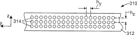
In another exemplary, the xsect of the optical element 310 that schematically shows as Fig. 3 B, fiber 314 is arranged in the two-dimensional array mode in matrix 312.In the illustrated embodiment, the spacing h between the adjacent fiber 314 on the y direction
yAnd the spacing h on the z direction between the adjacent fiber
zIdentical.But do not need so to schematically show the spacing h on the z direction as Fig. 3 C yet
zCan with the spacing h on the y direction
y Different.Optical element 310 can be a polarizer.
In another embodiment, for example as schematically showing among Fig. 3 D, fiber 314 can be setovered between adjacent two rows, forms hexagon and fills the fiber pattern of arranging.The another kind of regular pattern of fiber 314 can be adopted or the irregular pattern of fiber 314 can be adopted.
When effective, such arrangement mode is particularly useful for the light that is in second wave band (being different from first wave band) for the fiber that effectively is arranged in another row for the light that is in first wave band when the fiber that is arranged in a row.Consider this illustrative examples, wherein the fiber 314 among the first row 316a is effective for the reflect polarized light that is in the ruddiness bandwidth, and the fiber 314 among the second row 316b is effective for the reflect polarized light that is in the blue light bandwidth.Therefore, if with the mixed light illumination optical element 310 of ruddiness and blue light, the first row 316a of fiber 314 will see through all blue lights while transmissions with angle θ
1The ruddiness of polarization.The second row 316b of fiber 314 will be through with angle θ
1The transmission simultaneously of the ruddiness of polarization is parallel to angle θ
2The blue light of polarization.If angle θ
1And θ
2Differ 90 degree, element 310 is in transmission the ruddiness and the blue light that is on the vertical polarization attitude of a certain polarization state.The polarization direction of the blue light that is reflected equally, also with the polarization direction quadrature of the ruddiness that is reflected.Be appreciated that and fiber 314 row of varying number can be arranged with angle separately, and be used for separately colour band.
In some embodiments, the density of fiber 314 can be constant in optical element 300 and optical element 310, perhaps can change in optical element 300 and optical element 310.For example, the density of fiber 314 begins to reduce from a side of optical element 300 and optical element 310, also can otherwise change.For this characteristic further is shown, Fig. 3 F schematically shows the embodiment of optical element 310, and wherein the density of fiber 314 changes along the direction of traversing element 310.Particularly, for along traversing all positions of the direction y direction of element 310, the interval on the y direction between the adjacent fiber is not a constant.Fig. 3 G schematically shows optical element 310, and wherein the density of fiber 314 changes along the rip cutting direction of element 310.Particularly, for all positions along element 310 rip cutting direction z directions, the interval on the z direction between the adjacent fiber is not a constant.May have other variant, for example, the interval between the adjacent fiber may change on y direction and z direction simultaneously.
Fig. 3 H schematically shows another embodiment, and wherein optical element 320 has the polymer fiber 324 that embeds matrix 322.In this particular, centre distance reduces between the adjacent fiber 324 in zone, and this zone is positioned at this figure middle part (for the adjacent area of both sides).Therefore, this regional fill factor, curve factor increases, the mark of element 320 cross-sectional areas that fill factor, curve factor is promptly occupied by fiber 24.This variation of fill factor, curve factor can be used for (for example) and improve the uniformity of light of being launched and seen through element 320 by light source 326.For example, when element 320 was contained in the direct-view screen that is illuminated by discrete light source, this may be important: in this device, importantly provide the illumination uniform image for spectators.In the time of after light source places even diffusing globe, the light that sees through diffusing globe is the highest in the brightness of the top of light source.The variation of fill factor, curve factor can be used to increase the amount of diffusion directly over the light source 326 as shown in Fig. 3 H, thereby reduces the heterogeneity of transmitted intensity.
Optical element of the present invention can have flat surfaces, for example the flat surfaces that is parallel to the xy plane as shown in Figure 1A and Figure 1B.This element also can comprise one or more patterned surface, so that required optical effect to be provided, makes light see through polarizer or by polarizer reflection.For example, in the exemplary that schematically shows as Fig. 3 I, optical element 330 (can be polarizer) is formed by the matrix 332 that comprises number of polymers fiber 334 and may have one or more curved surface 336.Curved surface 336 provides focal power (focusing on or out of focus) for the light that sees through surface 336.In the embodiment that illustrates, ray 338 is represented the light example, and its polarization direction is parallel to the axis of homology of optical element 330 and is focused on by crooked refractive surface 336.In other exemplary, the incidence surface that light passes element 330 enters element 330, what this incidence surface can be for bending, perhaps can be other surface structure.In addition, exit surface can have surface structure, and transmitted ray sees through this surface and penetrates optical element 330.The example of surface structure comprises the structure such as fresnel lens structure etc.This structure also can provide focal power for the light that sees through patterned surface.
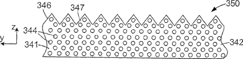
Except bending area or for replacing bending area, the patterned surface of incidence surface and/or exit surface also can comprise the straight burr zone.For example, in another exemplary, schematically show as Fig. 3 J, the optical element 340 that is formed by the matrix 342 that comprises polymer fiber 334 can have prismatic structures surface 346, and this surface is called as brightness and strengthens the surface.Brightness strengthens the LCD that the surface is generally used for for example back lighting, with the cone angle of the light that reduces to shine display board, thereby increases a last brightness for the observer.Non-normal incidence shown in the figure to two light 348 and 349 of element 340 as an example.Light 348 is in the polarization state by element 340 transmissions, and turns to the z axle by patterned surface 346.Light 349 is in by element 340 irreflexive polarization states.Brightness enhancing surface is set makes prism structure parallel with fiber 344, and parallel with the x axle as shown in the figure.In other embodiments, prism structure is provided with other angle with respect to machine direction.For example, rib ridge and y axle be arranged in parallel, perpendicular to fiber, perhaps with x axle and y axle with certain angle setting.
Can adopt suitable method on matrix, to form patterned surface.For example, solidify this matrix in stromal surface when surface such as the instrument of tools for micro replication etc. contacts, this tool surfaces produces required form on the polymer substrate surface.
Polymer fiber can be present in the zones of different of optical element.As Fig. 3 J, polymer fiber 344 is not positioned at the structure 347 that is formed by patterned surface 346, but only is positioned at the main body 341 of element 340.In other embodiments, the distribution difference of polymer fiber 344.For example, in optical element 350, schematically show as Fig. 3 K, polymer fiber 344 is positioned at the main body 341 of element 350 and the structure 347 that is formed by patterned surface 346.In another example, schematically show as Fig. 3 L, polymer fiber 344 only is arranged in the structure 347 of element 360 rather than the main body 341 of element 360.
Schematically show another exemplary of the present invention as Fig. 3 M, wherein element 370 has the polymer fiber 374 in matrix 372.In this particular, some fibre 374a does not embed in the matrix 372 fully, but exposes the surface 376 of matrix 372.
In some exemplary, place the polymer fiber in the polarizer to comprise some different types of polymeric materials, comprise at least a birefringent material and another kind of material (for example non-substantially birefringent material).These different materials can be arranged by different way, for example adopt orderly alternating layer, and perhaps the fine fibre with a kind of material places " pond " other material.The several different exemplary of the polymer fiber that comprises a plurality of interior birefringence interfaces are discussed below.The birefringence that host material has can not have birefringence less than the birefringent material of fiber, perhaps can have the birefringence of opposite nature.For example, as n in the birefringent material in the fruit fiber
xN
y, so may n in the host material
yN
x
In preferred exemplary, birefringent material is a kind of like this material, and it is refraction index changing after orientation.Like this, after the fiber orientation, produce the coupling or the mismatch of refractive index along direction of orientation.Careful control orientation parameter and other operating conditions, the positive birefringence of birefringent material or negative birefringence can be used for introducing on to dead axle the diffuse reflection or the transmission of one or two polarized lights.Relative ratio between transmission and the diffuse reflection is relevant with multiple factor, for example (but being not limited to), in the fiber on the size of the concentration at birefringence interface, fiber, the birefringence interface refringence square, size and shape and the incident light wavelength or the wavelength coverage at birefringence interface.
Scattering of light degree along the influence of the value of refractive index match on the specific axis or mismatch along this polarization.In general, scattered power and refractive index mismatch square is directly proportional.So, big more along the refractive index mismatch of specific axis, strong more along the scattering of light of this polarization.On the contrary, when along the refractive index mismatch of specific axis hour, and transmission that pass this body volume more little along the scattering of light degree of this polarization becomes specular transmission more.
If when the refractive index of the refractive index of certain non-birefringent material and birefringent material is complementary, the direction of an electric field incident light that is parallel to this polarization does not pass fiber with will having scattering so, and irrelevant with size, shape and the density of birefringent material part.In addition, if along this refractive index the refractive index match of the polymer substrate in the also basic and polarizer main body, light will not pass this main body with having scattering substantially so.At the intent of the present invention, when the difference of two refractive indexes during less than 0.05 (preferably less than 0.03,0.02 or 0.01), two refractive indexes are mated substantially.
If the refractive index between birefringent material and the non-birefringent material does not match along certain axle, fibre scattering or reflection are along the light of this polarization so.By the value decision of scatterer refractive index mismatch, the given cross sectional dimensions that this scatterer had is greater than about λ/30 at least in part for the intensity of this scattering, and wherein λ is the light wavelength that incides in the polarizer.Accurate size, shape and the arrangement at mismatch interface play decision from this interface to the various direction scatterings or the effect of reflecting how much light.If the density of scattering layer and thickness deficiency, according to the multiple scattering theory, incident ray can be reflected or absorb, rather than transmission, and irrelevant with the details of scatterer size and shape.
Before using polarizer, preferably, the stretched processing of fiber and permission size on the cross directional stretch in-plane direction are loose, and the refringence between birefringent material and the non-birefringent material is relatively large and less relatively along two other orthogonal axes along first like this.Electromagnetic radiation for different polarization states has produced big optical anisotropy like this.
Some polarizers in the scope of the invention are oval scattering polarizers.Usually, oval scattering polarizer adopts and has refringence the fiber of (along the birefringent material of draw direction and non-stretching direction and the refringence between the non-birefringent material), and can diffuse transmission or a kind of polarized light of diffuse reflection.Birefringent material in the fiber also can form and matrix material between the birefringence interface, in this case, these interfaces also can comprise stretch and the cross directional stretch direction on refractive index mismatch.
The ratio of forward scattering and back scattering depends on the refringence between birefringent material and the non-birefringent material, the concentration at birefringence interface, the size at birefringence interface and the gross thickness of shape and fiber.Usually, the refractive index of oval scatterer between birefringent material and non-birefringent material is less relatively.
Preferably choose the degree of orientation of the material that is used for fiber of the present invention and these materials, like this, birefringent material in the fiber of finishing and non-birefringent material have at least one such axle, and the refractive index relevant with this is equal substantially.The coupling of the refractive index relevant with this makes reflection of light does not take place substantially that this axle is (but optionally) crosscut direction of orientation usually on this plane of polarization.
An exemplary that has interior birefringence interface and can be used to the polymer fiber of more above-mentioned polarizer embodiments is a multi-layer fiber.Multi-layer fiber is to comprise the different polymeric materials of multilayer and wherein at least one is the fiber of birefringent material.In some exemplary, multi-layer fiber comprises the alternating layer of a plurality of first materials and second material, wherein first material is optically isotropic and second material is birefringent, and its refractive index along refractive index on the orthogonal axes and isotropic material is different with first material is roughly the same along the refractive index of an axle for second material.Such structure was for example being carried out more detailed the discussion in the U.S. Patent No. 5,882,774.
Fig. 4 A schematically shows the xsect of an exemplary of multi-layer fiber 400.Fiber 400 comprises the alternating layer of first material 402 and second material 404.First material be birefringent and second material for isotropic substantially, the interface between the adjacent two layers 406 is birefringent like this.In this particular, interface 406 may be substantially of the plane and extends along the length direction of fiber 400.
According to the required optical characteristics of fiber 400, fiber 400 can form layer and the different size with varying number.For example fiber 400 can form have about 10 layers to hundreds of layer and have the corresponding thickness scope.To the width of fiber 400 without limits, the preferred value of width can be at 5 μ m in the scope of about 5000 μ m, although fiber width also can exceed this scope.
As mentioned above, the example that can be used as the suitable polymeric material of birefringent material comprises PET, PEN and multiple its multipolymer.Some examples that can be used as the suitable polymeric material of non-birefringent material comprise aforesaid optical isotropy material.
Can adopt the multi-layer fiber of other structure.For example, another exemplary of multi-layer fiber 420 can be formed by first material 422 that replaces and the concentric layer of second material 424, and wherein first material 422 is birefringent, and second material 424 is isotropic.In this exemplary embodiment, fiber 420 comprises between alternating layer 422 and 424 and along concentric birefringence interface 426 that fiber 420 extends.
The skin 428 of fiber 420 can be formed with one of second material, be formed by the polymeric material identical with the polymer substrate material therefor of polarizer by first material, or is formed by certain other material.
Also can adopt multi-layer fiber with variety classes xsect.Such example is a multi-layer fiber 440, the xsect that schematically shows as Fig. 4 C.This fiber comprises a plurality of alternating layers of first material 442 and second material 444, wherein first material 442 be birefringent and second material 444 for optically isotropic.The birefringence interface 446 that forms between the different layers has flat 446a and sweep 446b and extends along fiber 440.The certain cross sectional of different layers mainly by the decision of the shape of the feed piece (feedblock) that is used for coextrusion fiber 440 and also by fiber 440 any subsequently form the step decision.
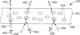
When multi-layer fiber comprised birefringence interface and its birefringence interface have flat on fiber cross section, the orientation that can be controlled at flat in the polarizer was to provide the selected effect in the certain limit.For example, in the exemplary of polarizer 450, schematically show as Fig. 4 D, polarizer 450 comprises the matrix 452 that has embedded fiber 454, and the birefringence interface of fiber 454 and the surface 456 of polarizer 450 are arranged in parallel.When incident light 458 was nonpolarized light, polarizer saw through the light 460 that is in a kind of polarization state and reflects the light 462 that is in the vertical polarization attitude.In the embodiment that illustrates, polarization direction reflected light 462 is parallel with plan with plane, figure place is vertical in the polarization direction of transmitted light 460.
In this exemplary, because being arranged as, the birefringence interface of fiber 454 is parallel to each other, reflected light 462 can comprise the composition of a large amount of direct reflections.For example because the cause of surface effect and diffraction effect, also because the cause of the deviation of strict collimation between the fiber 454, reflected light 462 also can comprise the scattering composition.In addition, because that the birefringence interface is arranged as is parallel with surperficial 456, so polarizer 450 becomes the reflection of light mirror that is in the polarization by reflection attitude in a way.
Fig. 4 E schematically shows the xsect of another exemplary polarizer 470.In this polarizer 470, fiber 454 is aligned to the flat at its birefringence interface almost is parallel to each other.Yet in this case, the flat at birefringence interface 456 is not arranged in parallel with the surface, but with surface 456 non-parallel arrangements.Non-polarized incident light 458 makes and is in light 460 transmissions of transmission-polarizing attitude and is in light 462 reflections of polarization by reflection attitude.In this case, when incident light impinges perpendicularly on surperficially 456 the time, reflected light 462 is reflected from the non-perpendicular direction on surface 456 usually.Can suppose that reflected light 462 is directed to a side of polarizer 470.
Schematically show the xsect of another exemplary polarizer 480 among Fig. 4 F.In this polarizer 480, fiber 454 is not to arrange in all parallel mode of the flat at birefringence interface, but traverses polarizer 480 with required location feature location.For convenience, definition angle θ is useful, and this angle is the angle that forms between the normal 484 on the normal 482 of flat at birefringence interface and surface 456.The θ value can be traversed polarizer 480 and be changed.In the embodiment that illustrates, the orientation of the fiber 454 in close polarizer 480 left sides makes the θ value be+θ
0Like this, the light 462L from this partial reflection of polarizer 480 is directed to the right side.The orientation of the fiber 454 on close polarizer 480 right sides makes the θ value be-θ
0, like this, be directed to the left side from the light 462R of this partial reflection of polarizer 480.At the polarizer middle part, the normal 482 of the flat at birefringence interface and the normal 484 substantially parallel (being θ=0) on surface 456 are so be reflected with the incident angle on the surface 456 substantially by the light 462C of polarizer 480 middle parts reflection.
What be appreciated that is to select θ to traverse the mode that polarizer 480 changes, thereby comes reflection ray with predetermined distribution.For example, in the embodiment that illustrates, reflected light focuses on before polarizer substantially.In another unshowned exemplary, the flat at birefringence interface can be oriented to and make reflected light focus in a side of polarizer, rather than in the polarizer prefocusing.
Fig. 4 G schematically shows another exemplary polarizer 490.In this polarizer 490, the flat random orientation at the birefringence interface of different fibers 454.Therefore, reflected light 462 is a diffuse reflection form more or less.
Being understandable that, can selecting the relative orientation of the flat at birefringence interface to make that reflected light is direct reflection or a diffuse reflection form more or less, perhaps is the reflected version of direct reflection and diffusing characteristic diffuser combination.
In some exemplary, fiber 454 along its length with respect to the surface 456 be maintained fixed towards.In other exemplary, some or whole fiber 454 can be along its length direction twisting.
Another exemplary with the polymer fiber at interior birefringence interface is a composition fiber, and it comprises the many scattering fibers that are dispersed in the polymkeric substance filling material.Fig. 5 A schematically shows the xsect of exemplary composition fiber example.Composition fiber 500 comprises many scattering fibers 502, and its filling material 504 is filled between the scattering fiber 502.In some embodiments, at least one in scattering fiber 502 or the filling material 504 is birefringent.For example, in some exemplary, at least some scattering fibers 502 can be made and filling material material 504 can be for non-birefringent by birefringent material.In other exemplary, scattering fiber 502 can be birefringent for non-birefringent filling material material 504.In other embodiments, scattering fiber 502 and filling material 504 can be birefringent.In these different variants, each interface 508 is the interfaces between birefringent material and the another kind of material between the material of scattering fiber 502 and the filling material material 504, promptly be the birefringence interface, and can make preferential reflection of the light that is in selected polarization state or scattering.In each of these different embodiments, the polymer substrate that composition fiber embeds wherein can be for optically isotropic or birefringence.
In some of the other embodiments, fiber 500 can be made by isotropic scattering fiber 502 and isotropy filling material material 504.In this case, the matrix that has wherein embedded fiber 500 is birefringent.
Optionally, composition fiber can have outer 506.Outer 506 can be used for (for example) influences composition fiber and has wherein embedded adhesion between the polymer substrate of composition fiber.In some embodiments, outer 506 can make by the material that increases the adhesion between composition fiber and the polymer substrate (for example vibrin coating, silane coating or other be used to increase the priming paint of the adhesion between polymer fiber and the polymer substrate).In other embodiments, outer 506 can make by the material that reduces adhesion between polymer fiber and the polymer substrate on every side (for example fluoro carbon materials, silicone material etc.).In some embodiments, can adopt outer 506 the antireflection function is provided, for example by between fiber 500 and polymer substrate on every side, providing some refractive index match to realize.
From the xsect of composition fiber, scattering fiber can be provided with at random, for example the exemplary that Fig. 5 A-Fig. 5 C schematically shows.Scattering fiber can adopt other xsect spread pattern.For example, scattering fiber 502 can be arranged in the xsect of composition fiber 530 regularly.For example, shown in Fig. 5 D, exemplary fiber 530 illustrates the scattering fiber of arranging with two-dimensional array form 502, the spacing d of the adjacent scattering fiber 502 on the y direction
ySpacing d with adjacent scattering fiber 502 on the z direction
zIdentical.In exemplary fiber 540, shown in Fig. 5 E, scattering fiber 502 is arranged with two-dimensional array form, wherein the spacing d on the y direction
yWith the spacing d on the z direction
z Different.Scattering fiber 502 among Fig. 5 D and Fig. 5 E is arranged as rectangular grid patterns, is appreciated that rectangular grid patterns comprises the square net pattern of Fig. 5 D.The interval of adjacent scattering fiber 502 can for (for example) in the scope from 50nm to 500nm, wherein composition fiber 530,540 is used for visible-range.
In other exemplary, scattering fiber 502 can form other pattern.For example, arranging scattering fiber makes it occupy some (but not being whole) positions in the regular array.In addition, may between adjacent scattering fiber or scattering fiber group, introduce space or gap.Can select the size and the spectral characteristic of distribution in such group or space and gap to be needed especially.For example thereby some arrangements of scattering fiber can be used as photonic crystal for the light in the particular range of wavelengths and obtain spectrum optionally reflection and/or transmission.Be filed on February 28th, 2005, title is for " composite polymer fibers (COMPOSITE POLYMERFIBERS) ", total U.S. Patent application No.11/068, and photonic crystal photon fiber further has been discussed among 158 (the attorney docket No.60371US002).
Other exemplary of composition fiber is described now, shown in it to the non exhaustive selection that may arrange of scattering fiber.
The exemplary exemplary that composition fiber 560 is shown among Fig. 5 H, some scattering fibers 502 are regularly arranged in the peripheral region at the center of fiber 560, but the middle part of fiber 560 does not have scattering fiber.In another embodiment of composition fiber 565, schematically show as Fig. 5 I, scattering fiber 502 is arranged in the concentric ring 506.Size and gap length and/or concentric ring size that can selective scattering fiber 502, to obtain specific optical property, for example transmission and/or reflecting properties.In the example shown in Fig. 5 I, shown in the position of scattering fiber ring of living in set by hexagonal mesh.This is not a necessary condition, and scattering fiber 502 can form concentric circles, schematically shows as Fig. 5 J.
In some embodiments, scattering fiber 502 needn't be identical size entirely.For example, the embodiment composition fiber 570 and 575 shown in Fig. 5 J and Fig. 5 K, composition fiber can comprise the scattering fiber of varying cross-section size.In these particular, the xsect of scattering fiber 502a is more relatively large than the xsect of scattering fiber 502b.Scattering fiber 502 can be divided into the group of at least two kinds of different sizes, and in fact, scattering fiber 502 can size have nothing in common with each other.In addition, for example shown in Fig. 5 I, scattering fiber 502 can be positioned at the middle part of composition fiber, and perhaps composition fiber middle part does not have scattering fiber 502: for example, shown in Fig. 5 J, scattering fiber 502a be positioned at composition fiber 570 around and not at the middle part.In fact, the size of scattering fiber 502 can be a scope rather than single value.In addition, different scattering fibers 502 can be made by different materials.
As mentioned above, composition fiber is not required to be circle, and can have non-circular cross sections.In the accompanying drawing, Fig. 6 A and Fig. 6 B illustrate non-circular composition fiber 600,610, and it comprises the scattering fiber 502 of squarely and hexagon pattern respectively.Whether for non-circular fiber, can make its scattering fiber 502 be positioned at each point place on the regular grid pattern, but all positions on the lattice all need relevant with scattering fiber 502.For example, the non-circular composition fiber 620 that Fig. 6 C schematically shows comprises the scattering fiber 502 that places hexagonal mesh point place, but has some gaps 612 between the fiber.In addition, the pattern that is formed by scattering fiber 502 does not have axis of symmetry.
Fig. 6 D and Fig. 6 E schematically show the non-circular composition fiber 630,640 of other exemplary.The xsect of these exemplary non-circular composition fibers 630,640 is square and comprises the scattering fiber 502 that is arranged in different exemplary patterns.Scattering fiber 502 in the composition fiber 630 is arranged in the hexagonal mesh pattern, and wherein the scattering fiber 502 in the composition fiber 640 is arranged in the square node pattern.In each case, has the gap in the arrangement mode of scattering fiber 502.
Scope intention of the present invention contains all spread patterns of composition fiber inscattering fiber.In some exemplary, can set the relative position of scattering fiber, the size of scattering fiber and the refringence between scattering fiber and the filling material material, make composition fiber under (for example) reflection and/or transmission situation, have required spectral selectivity.This spectral selectivity example includes but is not limited to reflection and transmission.In some embodiments of composition fiber, the position of scattering fiber on xsect can cause the non-coherent scattering of incident light.In other embodiments, thus the position of scattering fiber can cause the coherence effect of scattered light obtains the photonic crystal characteristic.The average density of scattering fiber in composition fiber can change on a large scale, for example greater than 1% to about 95%, is preferably about 10% to about 90%, and more preferably about 10% is about 50%, although scattering fiber density also can be beyond these scopes.Be filed on February 28th, 2005, title is for " composite polymer fibers (COMPOSITE POLYMER FIBERS) ", total U.S. Patent application No.11/068, among 158 (the attorney docket No.60371US002) composition fiber has been discussed further.
The size of scattering fiber 502 has significant impact to scattering.Fig. 7 illustrates the curve as the scattering efficiency of the function of scattering fiber mean radius (the proportional optical thickness of normalization (normalized scaled optical thickness) (NSOT)).NSOT is provided by following formula
NSOT=τ(1-g)/(tf)
Wherein τ is optical thickness and equals tk, and wherein k is the extinction cross-section (inverse of delustring mean free path) of per unit volume, and t is the thickness of scatterer, and f is the volume fraction of scatterer, and g is an asymmetry parameter.The g value is+1 for pure forward scattering, is-1 for pure back scattering, and is 0 for forward direction and back to the scattering that equates.Be used to obtain curve calculation assumption incident light wavelength in a vacuum be 550nm.
As can be seen, the scattering efficiency peak value is approximately the 150nm place at radius, and scattering efficiency to be approximately half value of maximal value be the scope place of about 50nm to 1000nm at radius.Scattering fiber can have any required cross sectional dimensions, but for its spectrum is the light of centre wavelength with 550nm, cross sectional dimensions can more preferably arrive in the scope of about 1000nm at about 100nm at about 50nm in the scope of about 2000nm.When scattering fiber had circular basically xsect, cross sectional dimensions was a diameter, and can be the width of scattering fiber for non-circular fiber cross section.When composition fiber is used for lambda1-wavelength outside limit of visible spectrum when (for example ultraviolet range or infrared spectral range), the size of scattering fiber can be different.Usually, scattering fiber cross sectional dimensions preferred range is that about 4 λ are arrived in about λ/10, and wherein λ is a light wavelength in a vacuum.When light wavelength was a scope, the λ value was taken as the intermediate value of wavelength coverage, but composition fiber also can have the scattering fiber of multiple size.
If scattering fiber is too thin, for example less than about 1/30 of optical wavelength in the composition fiber, the perhaps light of against vacuum medium wavelength 550nm, less than about 0.012 μ m, if and the density of scattering fiber is enough big, for example in the scope of about 60%-80% of composition fiber volume, polarizer can be used as the medium with effective refractive index so, along arbitrarily to this effective refractive index of dead axle roughly between scattering fiber refractive index and filling material refractive index.In this case, almost there is not light to be scattered.When the xsect size of scattering fiber becomes bigger when a lot of than wavelength, for example when becoming about at least 3 times or more times of wavelength, scattering efficiency becomes very low and produces the iris effect.
The cross sectional dimensions of scattering fiber can change according to the required purposes of optical material.Like this, for example, the size of scattering fiber can change according to the light wavelength of being paid close attention in the application-specific, and scattering or visible light transmissive, ultraviolet light and infrared light require to use different size.Yet, usually, in the material size of scattering fiber should by approximately greater than be in the material the concern wavelength coverage light minimum wavelength 1/30.
At the upper limit place of required size scope, the average-size of scattering fiber preferably be equal to or less than be in the material the twice of the light wavelength in the wavelength coverage of paying close attention to, preferably, less than 0.5 of required wavelength.
The density influence of composition fiber inscattering fiber produces the amount of scattering.What come in handy is, between the scattering fiber centre distance be about λ/10 to about 2 λ, wherein λ is the centre wavelength or the mean wavelength of incident ray wavelength in a vacuum.
The xsect of scattering fiber may be circle, but needn't and can have other shape of cross section for circle.In the example composition fiber 650 that schematically shows as Fig. 6 F, scattering fiber 652 has square cross section.Can adopt other shape of cross section, regular and irregular polygon for example, for example triangle, square or hexagon or have the shape of cross section of bent limit and straight flange concurrently.The shape of cross section of scattering fiber may be by the shape decision of extrusion die, perhaps by processing decision behind the optical element after extruding.Its intention is not to be the scattering fiber with these shape of cross sections shown in the accompanying drawing in order to limit to the present invention.
When the centre distance of fiber was inhomogeneous, it was useful adopting the scattering fiber with non-circular cross sections, because allow scattering fiber to occupy the more most of of composition fiber transverse cross-sectional area like this.For example, centre distance is the twice of centre distance on the z direction on rectangular node and the y direction if scattering fiber is arranged in, if scattering fiber has that length is the twice of length on the z direction on non-circular cross-section and its y direction so, be that circular situation is compared with scattering fiber then, scattering fiber has occupied the bigger xsect of composition fiber.
Fig. 6 G-Fig. 6 I schematically shows other exemplary arrangement of the scattering fiber with non-circular cross sections.Non-circular scattering fiber can be arranged in and make their shape of cross section arrange with random direction.In other embodiments, the xsect of scattering fiber can align mutually.For example, among Fig. 6 G, composition fiber 660 is formed by the filling material 504 that has embedded scattering fiber 662, and this scattering fiber 662 has non-circular cross-section.In this particular,, make that their major axis of non-circular cross-section is parallel with the y axle with scattering fiber 662 alignment.
Scattering fiber does not need to be arranged in makes their xsect all align, but different scattering fibers can have different alignment thereof in the composition fiber.In the exemplary composition fiber 670 that in Fig. 6 H, schematically shows, scattering fiber 672 has non-circular cross-section, and some fibre 672a is arranged in and makes that their major axis is parallel with the z axle, and other fibers 672b is arranged in and makes that their minor axis is parallel with the z axle simultaneously.Only about half of scattering fiber 672 is aimed on all directions.In addition, fiber 672a group and fiber 672b group are regularly arranged in the xsect of composition fiber 670.Be understandable that fiber 672a group and fiber 672b group also can irregular alignments in the xsect of composition fiber 670.
Shown in embodiment other variants can be arranged.For example not every scattering fiber must have same cross-sectional shape, size and arrange.In addition, can be aligned the xsect of scattering fiber, in composition fiber, to form pattern.Fig. 6 I schematically shows a kind of particular instance of this composition fiber 680.Scattering fiber embeds in the filling material 504, and this scattering fiber has two kinds of varying cross-section shapes, i.e. oval fibres 682 and circular fiber 684.In the illustrated embodiment, oval fibres 682 is arranged in and makes the minor axis of their non-circular cross-sections towards nearest circular fiber 684.Scattering fiber can adopt other pattern.
When scattering fiber had non-circular cross sections, the mode that scattering fiber can not twisted placed in the composition fiber, make so a certain surface of scattering fiber along scattering fiber length always towards a certain surface of composition fiber.In other exemplary, scattering fiber can be in twisting be placed on composition fiber, and like this along the different parts place on the scattering fiber length, a certain surface of scattering fiber can be towards the different surfaces of composition fiber.In many embodiments of composition fiber, the birefringence interface can or can be plane and misalignment for curved surface.In such embodiments, light at the birefringence boundary reflection to many different directions, so composition fiber can be described as light scatter.
Though refractive index mismatch is the main dependence factor of the scattering that polarization is relevant in the promotion composition fiber, the shape of cross section of composition fiber also can influence scattering.For example, when the scattering fiber xsect was ellipse, the shape of non-circular cross-section may cause the asymmetric diffusion of rear orientation light and forward scattering light.This effect can increase or reduce the scattered quantum that refractive index mismatch causes.
In some embodiments, scattering fiber can have skin-core structure, its SMIS is made by identical or different materials with skin, and perhaps core wherein is a hollow.Like this, for example, scattering fiber can be a hollow fiber, has even or non-homogeneous xsect.The inner space of fiber can be for sky, perhaps can be occupied by suitable medium (can be solid, liquid or gas, and can be organic or inorganic).Can consider that birefringence refringence at the interface selects the refractive index of this medium, to obtain the reflection or the scattering of required degree at the interface in birefringence.Suitable isotropy and birefringent polymer material have been discussed above.
A kind of method of making composition fiber is that the feed piece that is used to make composition fiber comes many scattering fibers of coextrusion, and composition fiber is also referred to as " fabric of island-in-sea type " fiber sometimes.At fibre science and technical manual: hi-tech pars fibrosa D (the 3rd volume; Lewin and Preston (editor), Marcel Dekker, 1996, ISBN 0-8247-9470-2) in gone through this method.Can adopt and comprise described those other fibre structure and the cross-sectional distribution of this list of references.Through after extruding, composition fiber can be stretched so that the birefringent material orientation.Be the U.S. Patent application No.11/068 of " COMPOSITE POLYMER OPTICAL FILMSWITH CO-CONTINUOUS PHASES " at title, described the method that coextrusion comprises the element of scattering fiber among 159 (the attorney docket No.60401US002) in more detail.
Example
In the example of coextrusion composition fiber, assembled feed piece to obtain two charging apertures and about 1000 " islands " outlet with 118 Laser Processing sheets and 11 vertical milling sheets.In the feed piece, polymer path is all isometric substantially.The xsect of the composition fiber of gained coextrusion shown in the photo of Figure 14.Composition fiber comprises PEN (90%)/PET (10%) multipolymer, and it is distributed in PETG copolyesters filling material " the sea " (Eastar that is provided by the Eastman Chemical company that is positioned at tennessee,USA Kingsport city as scattering fiber " island "
TM6763) lining.The about 200 μ m of the composition fiber diameter of extruding.Composition fiber is not stretched, and diameter can arrive about 25 μ m when still keeping its geometric configuration to stretch, and promptly its diameter reduces about 87%.After stretching like this, the interval between the scattering fiber will be 500nm.The cross sectional dimensions of scattering fiber will be by the flow rate ratio decision of two kinds of different polymeric materials.
Comprise the fibrous inner structure of multi-ply construction (coaxial and plane form) and many little scattering fibers in composition fiber (" island " fiber) by employing, perhaps pass through to adopt other method, as mentioned above can be so that polymer fiber has suitable optical property by the birefringence interface.The method that another kind is used to produce required inner structure (it comprises the polymeric birefringent interface in fiber) is for adopting immiscible two kinds of polymkeric substance (one of them is for birefringent at least) and they being extruded or cast or be shaped to fiber.Produce external phase and disperse phase through handling.Through processing or orientation subsequently, depend on the inner structure of polymer fiber, disperse phase can have shaft-like or layer structure.In addition, polymeric material can be oriented and make between two materials refractive index match on a polarization direction and have relatively large mismatch on another polarization direction.U.S. Patent No. 6,141, in 149 more detailed description the generation of disperse phase in membrane matrix.
This kind birefringent polymer fibers can be called as the disperse phase fiber.Schematically show the example of disperse phase fiber 800 among Fig. 8 A, promptly in external phase 804, have disperse phase 802.End face 806 is xsects, in order to the random distribution of disperse phase part 802 on fiber 800 xsects to be shown.Interface between matrix 804 and the disperse phase 802 is the birefringence interface, and Polarization-Sensitive reflection or scattering are taking place at the interface.
Disperse phase also can be formed by liquid crystal droplet, liquid crystal polymer or polymkeric substance.Can be that disperse phase can be made up of air (microcavity) for the another kind of mode of selecting for use.Under any circumstance, the interface between intrastitial disperse phase of disperse phase and the external phase can cause the optical characteristics that needs, and comprises polarization by reflection.
In the another kind of method of form dielectric grid polymer fiber, fiber can form by the mode similar to the generation type of composition fiber, and wherein first polymkeric substance is as filling material, and still second polymkeric substance and terpolymer are as scattering fiber.In some embodiments, second polymkeric substance and terpolymer are not dissolved each other, and at least one of second polymkeric substance and terpolymer is birefringent.Can mix and extrude second polymkeric substance and terpolymer and become the interior scattering fiber of composition fiber.After treatment, first polymkeric substance forms the filling material part of composition fiber, and scattering fiber comprises external phase and disperse phase, and external phase and disperse phase are obtained by second polymkeric substance and terpolymer respectively.This fiber is called as the disperse phase composition fiber.Fig. 8 B schematically shows the example of disperse phase composition fiber 850, and this example illustrates the scattering fiber 852 that comprises disperse phase 854.Scattering fiber 852 is surrounded by filling material 856.In other embodiments, scattering fiber can be made by second polymkeric substance and the 3rd material, and wherein the 3rd material is liquid crystal material, liquid crystal polymer or polymkeric substance.
Similarly, coaxial multi-layer fiber and non-coaxial multi-layer fiber can be made by alternating layer, and wherein a kind of layer comprises first polymkeric substance and second kind of layer comprises two kinds of immiscible polymkeric substance or mixtures of material.In these cases after treatment, produce such alternating layer: the some of them layer comprises first polymkeric substance and other layers comprise disperse phase and external phase.Preferably, external phase and/or disperse phase are birefringent.Through follow-up processing or orientation, second kind of interior disperse phase of layer can have shaft-like or hierarchy.
Is similar to the intrastitial scattering fiber of layering or the dimensional requirement in birefringence zone in all different embodiments.According to required operation wavelength or wavelength coverage, the size of the fiber that zooms in or out suitably or the thickness in multi-layered devices middle level are to obtain system's required size ratio, and this system comprises layer or the fiber that comprises external phase and disperse phase.
With reference to figure 9 the another kind of polymer fiber that can be used for polarizer of the present invention is described.Fiber forms yarn 900.In some embodiments of yarn 900, fiber is formed by many birefringent polymer fibers 902 twisted together, for example realizes by a large amount of multi-layer fibers of twisted, disperse phase fiber, composition fiber and/or disperse phase composition fiber.Can form yarn 900 by fiber milling with orientation, perhaps can be by the isotropic fiber twisted is formed yarn 900, wherein fiber is made by the material that can be orientated, and stretch yarn 900 is to be orientated the material that can be orientated then.
Some potteries also have enough little crystalline size, if when embedding their in the polymer substrate of the refractive index with suitable coupling, they can be rendered as transparent.Can derive from the Nextel of the 3M company that is positioned at St.Paul city, Minn.
TMCeramic fiber is the example of this material, and can be used as line, yarn and fabric pad use.At document
Chemistry Of Glasses second edition(A.Paul.Chapman and Hall, 1990) and
Introduction to The Ceramics second editionSuitable pottery or glass ceramic material have been further described in (W.D.Kingery, John Wiley and Sons, 1976).
The suitable birefringent polymer material that is used in the yarn 900 includes but is not limited to: the polymkeric substance that comprises PET, PEN; The multipolymer that comprises terephthalate and/or naphthalate.In other methods, yarn 900 can comprise the birefringent fiber of twisted, for example multilayer or composition fiber.
Usually, extend along the direction of fiber at the birefringence interface of polymer fiber.In some exemplary, birefringent fiber and x axle be arranged in parallel, and the major part that diffuses like this is dispersed into the plane y-z plane vertical with fiber, and does not almost have scattering in the x-z plane.
With reference to figure 10A-Figure 10 D, a kind of method of making polarizer of the present invention is discussed now.Schematically show as Figure 10 A, polymer fiber 1002 is arranged on first polymeric layer 1004.As Figure 10 B, the second polymer layer 1006 can water and cast from the polymer fiber 1002.First polymeric layer 1004 and the second polymer layer 1006 can be made by the same polymer material, perhaps can be made by different materials.If desired, can adopt several different methods (for example, heating and pressurization, solvent coating and drying, in-situ polymerization or its combination) to make between the second polymer layer 1006 infiltrated fibers 1002.
Also the part of fiber 1002 as one or more fabric can be arranged on the ground floor 1004.Schematically show fabric 1206 among Figure 12, wherein polymer fiber 1002 forms warp and transverse fiber 1208 formation parallels.Transverse fiber 1208 can be made by suitable organic or inorganic fibers, can be for example polymer fiber (for example isotropy and/or birefringent polymer fibers) or natural fiber (for example cotton yarn, silkworm yarn or hemp).In other exemplary, transverse fiber 1208 can be glass fibre, for example E-glass or S-glass fibre, aforesaid glass-ceramic fibre or ceramic fiber.The refractive index of transverse fiber 1208 can be substantially and the refractive index match of on every side polymer substrate, makes transverse fiber reduce for the optical effect that sees through the light in the polarizer.In addition, not all meridional fibers need be for comprising the polymer fiber at birefringence interface.For example, some meridional fibers to be also can being isotropic fiber, and can be formed by the fiber identical with the transverse fiber kind.In some embodiments, meridional fibers 1002 can be for having the fiber at birefringence interface, and the effect that reflection or scattering are in the polarized light of another specific wavelength band is played at this birefringence interface.
Can adopt weaving of any appropriate to handle and form fabric.For example, fabric can be plain cloth, twills, satin fabric or certain other fabric as shown in the figure.In some exemplary, the birefringent fiber 1002 in the fabric is more flat relatively, for example the part xsect that schematically shows as Figure 13 A.Notice that this figure meets the agreement that birefringent fiber wherein 1002 is basic and the x direction is arranged in parallel.In some exemplary, polymer fiber (for example composition fiber or multi-layer fiber) in fabric, keep single towards and without twisting.
In other embodiments, the polymer fiber 1002 in the fabric does not need for flat.Figure 13 B schematically shows in the fabric 1206 the part xsect as example.Importantly, notice that the view among this figure is different with Figure 13 A.Figure 13 A illustrates the side of transverse fiber 1208, and Figure 13 B illustrates the side of polymer fiber 1002.This coordinate axis is consistent with used coordinate axis in the described accompanying drawing of preamble, thus polymer fiber 1002 that direction is set is basic parallel with the x axle.But because polymer fiber 1002 rises and falls fabric 1206 in, the birefringence interface of polymer fiber 1002 entirely and the strictness of x axle be arranged in parallel.Correspondingly, can be by the light of fiber 1002 reflections or scattering with the different angles scattering in the x-z plane.In this accompanying drawing, light 1302 incides fiber 1002, and its direction is perpendicular to the x axle, and the part of light 1302 reflects with angle [alpha], be incident on " following domatic " or " go up domatic " of polymer fiber 1002 according to light 1302, its one-component is on positive x direction or negative x direction.Like this, polymer fiber 1002 also can be with the reflected light diffusion in the x-z plane.Diffuse reflection degree in the x-z plane depends on the shape of fabric interpolymer fiber 1002: not parallel with the x direction part of polymer fiber 1002 is many more, and the angular distribution of light in the x-z plane is big more.
Can form polarizer with batch process or continuous processing mode.In handling continuously, preferably, birefringent fiber 1002 (preferably in bundle or fabric) is placed on first polymeric layer 1004, then the second polymer layer 1006 can direct casting on birefringent fiber 1002.Can solidify or solidify the second layer 1006 then.
If desired, can increase the succeeding layer of polymer fiber 1002 extra plays and polymeric material 1008.For example Figure 10 C and Figure 10 D are illustrated in and add one group of polymer fiber 1002 on the second polymer layer 1006 and apply terpolymer layer 1008.
In the other method of Gong selecting for use of making polarizer, the polymer film 1004 with certain required optics, physics or character of surface can be used as the substrate that fiber 1002 is set.Can apply thermoplasticity or thermoset resin or curable compositions as second polymer film 1006 to see through one or more layers fiber 1002, can apply second substrate 1008 then, to form sandwich structure around second polymer film 1006 that forms at fiber 1002 with by resin or curable compositions.Make curable resin curing, sclerosis or generation chemical reaction to form lamination then.In this case, substrate 1004,1008 can be made or can be made by different materials by same material (such as thermoplastic resin, thermoset resin or curable compositions etc.).Can adopt a large amount of contact adhesives and hotmelt to replace thermoplasticity or thermoset resin or curable compositions to be used for the second layer 1006.In some embodiments, first substrate 1004 and second substrate 1008 can tight adhesion in the thermoplasticity that comprises fiber 1002 or thermoset resin or curable compositions 1006.In other embodiments, first substrate 1004 and second substrate 1008 can be removed.
In another manufacturing has illustrative methods more than the polarizer of one deck birefringent fiber, can be in a single step two-layer or more multi-layered fiber be arranged at above first polymeric layer, then second layer polymeric material be cast on the fiber as polymer substrate.
Have in the illustrative methods of polarizer of composition fiber in another manufacturing, can remove the filling material of composition fiber, for example realize by filling material being dissolved in the solvent before in composition fiber embedded polymer thing matrix.Then can be with polymer substrate as the filling material between the scattering fiber of composition fiber.This method is particularly useful when composition fiber is the form of bundle or fabric.
The appropriate method of making composition fiber comprises extrudes the composition fiber with birefringence scattering fiber and solubility filling material.Suitable water-soluble filling material comprises polyvinylpyrrolidone, cellulose acetate and polyvinyl alcohol (PVA).Suitable polyvinyl alcohol (PVA) comprises the polyvinyl alcohol (PVA) of being made by polyvinyl acetate hydrolysis (degree is about 70% to 95%).
Scattering fiber can be extruded with array way, is orientated by adding hot-extrudable array and applying suitable tension, makes scattering fiber be stretched to certain extensibility to obtain required refractive index value.
The scattering fiber orientation array that is used to form composition fiber can form yarn.Optionally, yarn also can be in conjunction with the fiber of other kind.Preferably, by forming fibrous bundle or fiber weaving being formed fabric, yarn is orientated on single direction.Can remove the soluble polymer filling material by extruding the back at any stage cleaning yarn of making yarn.
Scattering fiber after the cleaning can be immersed by fluid (preferably curable resin fluid).Can adopt any appropriate technology hardening resin, for example can comprise the matrix of fiber with formation by heat curing and/or radiation curing resin.In some exemplary, cured resin is so that matrix has flat surface.In other exemplary, can cured resin on one or more surface, to obtain desired structure.For example, can be with resin solidification when resin surface contacts with the microstructured surface of tools for micro replication.The example of suitable microstructured surface comprises the metal surface of machining, the replisome of electroforming or molded polymer film.The example that is formed at the suitable microstructure of stromal surface comprises linear prismatic structures, non-linear prism structure, Fresnel surface and lenticule etc.
Embodiments more of the present invention can be used for (for example) liquid crystal display (LCD) system and other polarization display system.For example, above-mentioned reflective polarizer based on fiber can be used to make the light generation polarization that sends and propagate into the LCD screen from LCD system back light.Such system includes but is not limited to: LCD-TV and LCD display monitor central monitoring system, mobile telephone display and other electronic equipment, and for example by digital camera and the video camera of LCD screen to user's display message.
Should not be considered as the present invention and be only limited to above-mentioned particular instance, but should think and the present invention includes all aspects of the present invention that clearly propose as in the appended claims.After reading this instructions, it is evident that concerning those skilled in the art in the invention the present invention is applicable to various modifications, equivalent processes and multiple structure.Claims are intended to comprise these modifications and design.
Claims (10)
1. optical body, this optical body comprises:
Polymer substrate; With
Place many polymer fibers in the described polymer substrate, wherein at least one described polymer fiber comprises a plurality of birefringence interfaces that are used for reflection ray, described birefringence interface is formed between first polymeric material and second polymeric material, at least one is a birefringence in described first polymeric material and second polymeric material, extend in the inside of at least one described polymer fiber and along the axle of described at least one polymer fiber at described birefringence interface, described polymer fiber is oriented as basic parallel with first, be different from along being parallel to second the light of direction polarization in described birefringence refringence at the interface along the light that is parallel to described first direction polarization in described birefringence refringence at the interface, described second with described first quadrature.
2. optical body according to claim 1, wherein said polymer fiber comprises at least one composition fiber, and described at least one composition fiber comprises the many scattering polymer fibers of being made by described first polymeric material that embed in described second polymeric material.
3. optical body according to claim 2, wherein at least some described scattering polymer fibers are arranged in regular pattern on the xsect of described composition fiber.
4. optical body according to claim 2, wherein at least one described scattering polymer fiber comprises the disperse phase that the terpolymer material in the external phase that is in described second polymeric material formation constitutes.
5. optical body according to claim 1, wherein said polymer fiber comprise the alternating layer of described first polymeric material and described second polymeric material.
6. optical body according to claim 5, the described alternating layer of wherein said first polymeric material and described second polymeric material is a concentric arrangement.
7. optical body according to claim 1, wherein said polymer fiber comprise at least a disperse phase fiber, and described disperse phase fiber comprises the disperse phase that described first polymeric material in the external phase that is in described second polymeric material formation constitutes.
8. optical body according to claim 1, this optical body also comprises fabric, and this fabric is placed in the described polymer substrate, and described fabric comprises described many polymer fibers.
9. optical body according to claim 1, wherein said polymer substrate forms the layer with at least one patterned surface.
10. optical body, this optical body comprises:
Optical material, it has first refractive index n along first
x, along having second refractive index n perpendicular to described first second
yWith
The polymer fiber that extends, it is parallel to described first and places in the described optical material; Described polymer fiber comprises first birefringent material, and this first birefringent material is along described first extension, and has first refractive index n along described first
1x, have second refractive index n along described second
1y, n wherein
1xBe different from n
1yThe polymer fiber of described extension comprises second material, and this second material is along described first extension, and has first refractive index n along described first
2x, have second refractive index n along described second
2yDescribed optical body to along the incident scattering of light of described first polarization with different to incident scattering of light along described second polarization.
Applications Claiming Priority (2)
| Application Number | Priority Date | Filing Date | Title |
|---|---|---|---|
| US11/068,157 | 2005-02-28 | ||
| US11/068,157 US7356229B2 (en) | 2005-02-28 | 2005-02-28 | Reflective polarizers containing polymer fibers |
Publications (2)
| Publication Number | Publication Date |
|---|---|
| CN101128759A CN101128759A (en) | 2008-02-20 |
| CN100504462C true CN100504462C (en) | 2009-06-24 |
Family
ID=36593664
Family Applications (1)
| Application Number | Title | Priority Date | Filing Date |
|---|---|---|---|
| CNB2006800063733A Expired - Fee Related CN100504462C (en) | 2005-02-28 | 2006-02-15 | Reflective polarizer containing polymer fibers |
Country Status (10)
| Country | Link |
|---|---|
| US (2) | US7356229B2 (en) |
| EP (2) | EP2166384B1 (en) |
| JP (1) | JP4805959B2 (en) |
| KR (1) | KR101237596B1 (en) |
| CN (1) | CN100504462C (en) |
| AT (1) | ATE456813T1 (en) |
| DE (1) | DE602006012021D1 (en) |
| MY (1) | MY142969A (en) |
| TW (1) | TW200641411A (en) |
| WO (1) | WO2006093660A1 (en) |
Families Citing this family (86)
| Publication number | Priority date | Publication date | Assignee | Title |
|---|---|---|---|---|
| TWI341339B (en) | 2004-03-30 | 2011-05-01 | Teijin Fibers Ltd | Island-in-sea type composite fibers and process for producing same |
| US7997771B2 (en) | 2004-06-01 | 2011-08-16 | 3M Innovative Properties Company | LED array systems |
| JP4671811B2 (en) * | 2004-11-05 | 2011-04-20 | 日立オートモティブシステムズ株式会社 | Finger authentication device |
| WO2007044028A2 (en) * | 2004-11-30 | 2007-04-19 | Agoura Technologies, Inc. | Applications and fabrication techniques for large scale wire grid polarizers |
| US7356231B2 (en) * | 2005-02-28 | 2008-04-08 | 3M Innovative Properties Company | Composite polymer fibers |
| US7356229B2 (en) * | 2005-02-28 | 2008-04-08 | 3M Innovative Properties Company | Reflective polarizers containing polymer fibers |
| US20060257678A1 (en) * | 2005-05-10 | 2006-11-16 | Benson Olester Jr | Fiber reinforced optical films |
| US8023065B2 (en) * | 2005-06-24 | 2011-09-20 | 3M Innovative Properties Company | Optical element for lateral light spreading in edge-lit displays and system using same |
| US7322731B2 (en) * | 2005-06-24 | 2008-01-29 | 3M Innovative Properties Company | Color mixing illumination light unit and system using same |
| US7903194B2 (en) * | 2005-06-24 | 2011-03-08 | 3M Innovative Properties Company | Optical element for lateral light spreading in back-lit displays and system using same |
| EP1912469A4 (en) * | 2005-08-02 | 2009-01-07 | Teijin Fibers Ltd | Speaker formed with screen as a unitary block |
| US20070153384A1 (en) * | 2005-12-30 | 2007-07-05 | Ouderkirk Andrew J | Reinforced reflective polarizer films |
| US20070153162A1 (en) * | 2005-12-30 | 2007-07-05 | Wright Robin E | Reinforced reflective polarizer films |
| US20070237938A1 (en) * | 2006-03-31 | 2007-10-11 | 3M Innovative Properties Company | Reinforced Optical Films |
| US20080274293A1 (en) * | 2006-03-31 | 2008-11-06 | 3M Innovative Properties Company | Spiral Multilayer Fibers |
| US20070236938A1 (en) * | 2006-03-31 | 2007-10-11 | 3M Innovative Properties Company | Structured Composite Optical Films |
| US7327923B2 (en) * | 2006-03-31 | 2008-02-05 | 3M Innovative Properties Company | Spiral multilayer fibers |
| US20070236939A1 (en) * | 2006-03-31 | 2007-10-11 | 3M Innovative Properties Company | Structured Composite Optical Films |
| US20070281143A1 (en) * | 2006-06-05 | 2007-12-06 | Aylward Peter T | Diffusely-reflecting element and method of making |
| US20070281157A1 (en) * | 2006-06-05 | 2007-12-06 | Laney Thomas M | Reflective polarizer, fiber, and process for making |
| US20080057277A1 (en) * | 2006-08-30 | 2008-03-06 | 3M Innovative Properties Company | Polymer fiber polarizers |
| US7773834B2 (en) | 2006-08-30 | 2010-08-10 | 3M Innovative Properties Company | Multilayer polarizing fibers and polarizers using same |
| US7599592B2 (en) * | 2006-08-30 | 2009-10-06 | 3M Innovative Properties Company | Polymer fiber polarizers with aligned fibers |
| US20080055724A1 (en) * | 2006-08-30 | 2008-03-06 | 3M Innovative Properties Company | Optical devices containing birefringent polymer fibers |
| JP4924114B2 (en) * | 2007-03-09 | 2012-04-25 | 株式会社ニコン | Image processing program and image processing method |
| EP2160644B1 (en) | 2007-05-20 | 2019-05-01 | 3M Innovative Properties Company | Semi-specular components in hollow cavity light recycling backlights |
| JP5336475B2 (en) | 2007-05-20 | 2013-11-06 | スリーエム イノベイティブ プロパティズ カンパニー | Optical recycling hollow cavity type display backlight |
| US9028108B2 (en) | 2007-05-20 | 2015-05-12 | 3M Innovative Properties Company | Collimating light injectors for edge-lit backlights |
| EP2487535A1 (en) | 2007-05-20 | 2012-08-15 | 3M Innovative Properties Company | Design parameters for backlights, which have a thin hollow cavity and recycle the light |
| CN101589183B (en) * | 2007-06-19 | 2011-12-07 | 日东电工株式会社 | Polarizing fiber, polarizing element, polarizing plate, layered optical film, and image display |
| EP2170591A1 (en) * | 2007-07-03 | 2010-04-07 | 3M Innovative Properties Company | Method of forming composite optical film |
| JP5314013B2 (en) * | 2007-07-03 | 2013-10-16 | スリーエム イノベイティブ プロパティズ カンパニー | Backlight assembly having a transmissive optical film (OPTICAL FILM) |
| US8848132B2 (en) | 2008-02-07 | 2014-09-30 | 3M Innovative Properties Company | Hollow backlight with structured films |
| KR20100126389A (en) | 2008-02-22 | 2010-12-01 | 쓰리엠 이노베이티브 프로퍼티즈 컴파니 | Backlights having selected output light flux distributions and display systems using same |
| KR20100126463A (en) * | 2008-03-05 | 2010-12-01 | 쓰리엠 이노베이티브 프로퍼티즈 컴파니 | Color shifting multilayer polymer fibers and security articles containing color shifting multilayer polymer fibers |
| JP5063579B2 (en) * | 2008-03-11 | 2012-10-31 | 日東電工株式会社 | Manufacturing method of light diffusion film |
| KR20090120074A (en) * | 2008-05-19 | 2009-11-24 | 웅진케미칼 주식회사 | Brightness enhancement film |
| EP2294478A2 (en) * | 2008-05-30 | 2011-03-16 | 3M Innovative Properties Company | Suspended optical film |
| JP5819723B2 (en) | 2008-06-04 | 2015-11-24 | スリーエム イノベイティブ プロパティズ カンパニー | Hollow backlight with tilted light source |
| JP2012507118A (en) | 2008-10-27 | 2012-03-22 | スリーエム イノベイティブ プロパティズ カンパニー | Semi-specular hollow backlight with gradient extraction |
| JP5245749B2 (en) * | 2008-11-19 | 2013-07-24 | 住友電気工業株式会社 | Phase plate and phase plate manufacturing method |
| KR101040930B1 (en) * | 2008-12-22 | 2011-06-16 | 웅진케미칼 주식회사 | High luminance multifunctional plate combined by diffusion plate, method of manufacturing thereof and liquid crystal display equipped with them |
| KR101040931B1 (en) * | 2008-12-23 | 2011-06-16 | 웅진케미칼 주식회사 | Slim multifunctional plate for lcd tv, method of manufacturing thereof and back light unit equipped with them |
| TWI404981B (en) * | 2009-01-30 | 2013-08-11 | Woongjin Chemical Co Ltd | Optical-modulation object |
| WO2010087598A2 (en) * | 2009-01-30 | 2010-08-05 | 웅진케미칼 주식회사 | Brightness enhancement film |
| KR100975351B1 (en) * | 2009-01-30 | 2010-08-11 | 웅진케미칼 주식회사 | Brightness enhancement film |
| KR100950949B1 (en) * | 2009-01-30 | 2010-04-02 | 웅진케미칼 주식회사 | Fabricating method of luminance-increasing woven fabric with double refraction sea-island fiber and fabricating method of luminance-increasing sheet and liquid crystal display using thereof |
| KR100950948B1 (en) * | 2009-01-30 | 2010-04-02 | 웅진케미칼 주식회사 | Luminance-increasing woven fabric using double refraction sea-island fiber and luminance-increasing sheet and liquid crystal display using thereof |
| KR100955471B1 (en) * | 2009-01-30 | 2010-04-30 | 웅진케미칼 주식회사 | Brightness enhancement film |
| KR100955474B1 (en) * | 2009-01-31 | 2010-04-30 | 웅진케미칼 주식회사 | Manufacturing method of brightness enhancement film |
| KR100955473B1 (en) * | 2009-01-31 | 2010-04-30 | 웅진케미칼 주식회사 | Method for manufacturing brightness enhancement film using vacuum hot press and brightness enhancement film prepared by the same |
| KR101040932B1 (en) * | 2009-02-06 | 2011-06-16 | 웅진케미칼 주식회사 | High luminance multifunctional plate and liquid crystal display equipped with them |
| KR101040933B1 (en) * | 2009-02-06 | 2011-06-16 | 웅진케미칼 주식회사 | High luminance multifunctional plate and liquid crystal display equipped with them |
| US9284108B2 (en) | 2009-02-23 | 2016-03-15 | Graphic Packaging International, Inc. | Plasma treated susceptor films |
| US20110011854A1 (en) * | 2009-02-23 | 2011-01-20 | Middleton Scott W | Low crystallinity susceptor films |
| KR101666570B1 (en) * | 2009-06-15 | 2016-10-17 | 삼성디스플레이 주식회사 | Liquid crystal display apparatus and method of manufacturing the same |
| KR101103378B1 (en) * | 2009-08-13 | 2012-01-06 | 웅진케미칼 주식회사 | Brightness enhancement film preparing and film prepared from the same |
| US20110075262A1 (en) * | 2009-09-28 | 2011-03-31 | Chao-Ying Lin | Asymmetric light diffuser and methods for manufacturing the same |
| CN102576119B (en) | 2009-10-24 | 2014-03-26 | 3M创新有限公司 | Light source and display system incorporating same |
| KR101729805B1 (en) | 2009-10-24 | 2017-04-24 | 쓰리엠 이노베이티브 프로퍼티즈 컴파니 | Gradient low index article and method |
| EP2491440A4 (en) | 2009-10-24 | 2018-05-02 | 3M Innovative Properties Company | Voided diffuser |
| KR101716922B1 (en) | 2009-12-08 | 2017-03-15 | 쓰리엠 이노베이티브 프로퍼티즈 컴파니 | Optical constructions incorporating a light guide and low refractive index films |
| WO2011078434A1 (en) * | 2009-12-24 | 2011-06-30 | 웅진케미칼 주식회사 | Liquid crystal display apparatus |
| KR101167777B1 (en) * | 2010-04-02 | 2012-07-25 | 웅진케미칼 주식회사 | Liquid crystal display |
| SG184855A1 (en) | 2010-04-12 | 2012-11-29 | 3M Innovative Properties Co | Light directing film |
| KR20130092971A (en) | 2010-04-14 | 2013-08-21 | 쓰리엠 이노베이티브 프로퍼티즈 컴파니 | Patterned gradient polymer film and method |
| GB201008181D0 (en) * | 2010-05-17 | 2010-06-30 | Airbus Operations Ltd | A device for locating a first aerospace component relative to a second aerospace component |
| JP5585222B2 (en) * | 2010-06-08 | 2014-09-10 | トヨタ紡織株式会社 | Fiber structure and manufacturing method thereof |
| US8889572B2 (en) | 2010-09-29 | 2014-11-18 | Milliken & Company | Gradient nanofiber non-woven |
| US8795561B2 (en) | 2010-09-29 | 2014-08-05 | Milliken & Company | Process of forming a nanofiber non-woven containing particles |
| US8789981B2 (en) | 2010-10-01 | 2014-07-29 | 3M Innovative Properties Company | Light directing expandable envelope |
| US8559779B2 (en) | 2010-10-08 | 2013-10-15 | The Boeing Company | Transparent composites with organic fiber |
| WO2012108674A2 (en) * | 2011-02-09 | 2012-08-16 | 웅진케미칼 주식회사 | Method and apparatus for manufacturing a reflective polarizer having a dispersed polymer |
| SG194043A1 (en) | 2011-04-04 | 2013-11-29 | 3M Innovative Properties Co | Optical stack comprising adhesive |
| US9377575B2 (en) | 2012-10-17 | 2016-06-28 | Samsung Electronics Co., Ltd. | Light guide plate, planar light apparatus, and display device |
| WO2015005584A1 (en) * | 2013-07-10 | 2015-01-15 | 한국생산기술연구원 | Method for manufacturing oriented-fiber composite material, oriented-fiber composite material manufactured thereby, reflective polarizing light film comprising oriented-fiber composite material, and method for manufacturing reflective polarizing light film |
| US10928563B2 (en) | 2013-10-02 | 2021-02-23 | 3M Innovative Properties Company | Microstructured diffuser comprising first microstructured layer and coating, optical stacks, and method |
| US10113089B2 (en) | 2013-10-02 | 2018-10-30 | 3M Innovative Properties Company | Articles and methods comprising polyacrylate primer with nitrogen-containing polymer |
| US9850405B2 (en) | 2013-10-02 | 2017-12-26 | 3M Innovative Properties Company | Article comprising polyacrylate pressure sensitive primer and adhesive comprising polyacrylate component |
| US9442344B2 (en) * | 2014-06-02 | 2016-09-13 | Vadient Optics, Llc | Nanocomposite high order nonlinear optical-element |
| KR102303956B1 (en) * | 2014-09-30 | 2021-09-27 | 엘지디스플레이 주식회사 | Switchable polarization lens, the method of manufacturing the same, and 2-dimensional and 3-dimensional image display device using the same |
| CN104865629B (en) * | 2015-06-05 | 2017-09-29 | 京东方科技集团股份有限公司 | A kind of reflective polaroid and liquid crystal display device |
| KR102106810B1 (en) * | 2016-02-25 | 2020-05-06 | 한국생산기술연구원 | Manufacturing method of light-diffusing film and backlight unit |
| JP6683021B2 (en) * | 2016-06-02 | 2020-04-15 | 三菱電機株式会社 | Air purifier |
| CN110622048B (en) | 2017-03-02 | 2023-03-28 | 3M创新有限公司 | Dynamic reflective color film with low optical thickness sensitivity |
| KR102426438B1 (en) * | 2020-08-26 | 2022-07-27 | 도레이첨단소재 주식회사 | Optical film for enhancing contrast ratio and viewing angle, polarizing plate comprising the same, and liquid crystal display apparatus comprising the same |
Citations (6)
| Publication number | Priority date | Publication date | Assignee | Title |
|---|---|---|---|---|
| US2604817A (en) * | 1948-10-14 | 1952-07-29 | Du Pont | Light polarizing composition |
| CN1063449A (en) * | 1991-01-22 | 1992-08-12 | 唐化学原料公司 | lamellar polymeric body and preparation method thereof |
| US5882774A (en) * | 1993-12-21 | 1999-03-16 | Minnesota Mining And Manufacturing Company | Optical film |
| CN1212763A (en) * | 1996-02-29 | 1999-03-31 | 美国3M公司 | Optical film |
| CN1212761A (en) * | 1996-02-29 | 1999-03-31 | 美国3M公司 | Method for making optical film |
| CN1316060A (en) * | 1998-07-31 | 2001-10-03 | 3M创新有限公司 | Post-forming continuous/disperse phase optical bodies |
Family Cites Families (100)
| Publication number | Priority date | Publication date | Assignee | Title |
|---|---|---|---|---|
| US2403731A (en) * | 1943-04-01 | 1946-07-09 | Eastman Kodak Co | Beam splitter |
| US2687673A (en) * | 1949-04-04 | 1954-08-31 | Boone Philip | Textile material having oriented fibers |
| US4019844A (en) * | 1973-02-26 | 1977-04-26 | Toray Industries, Inc. | Apparatus for producing multiple layers conjugate fibers |
| JPS5641234A (en) * | 1979-09-10 | 1981-04-17 | Asahi Chem Ind Co Ltd | Novel molding dope composition |
| US4477522A (en) * | 1983-04-11 | 1984-10-16 | Sherwood Research Corporation | Reinforcing element and method of making the same |
| US4560411A (en) * | 1983-05-20 | 1985-12-24 | Bm Chemie Kunststoff Gmbh | Aggregate for concrete or mortar |
| US4666485A (en) | 1984-12-03 | 1987-05-19 | Owens-Corning Fiberglas Corporation | Method and apparatus for making tapered mineral and organic fibers |
| US5059482A (en) * | 1988-09-13 | 1991-10-22 | Kuraray Company, Ltd. | Composite fiber and process for producing the same |
| US4963151A (en) * | 1988-12-28 | 1990-10-16 | Trustees Of The University Of Pennsylvania | Reinforced bone cement, method of production thereof and reinforcing fiber bundles therefor |
| US5047288A (en) * | 1989-03-31 | 1991-09-10 | Kuraray Company Limited | Nonwoven fabric comprising single filaments and filament bundles that yield improved impact resistant molded articles |
| US5486949A (en) * | 1989-06-20 | 1996-01-23 | The Dow Chemical Company | Birefringent interference polarizer |
| US5251065A (en) * | 1991-07-31 | 1993-10-05 | Kuraray Co., Ltd. | Polarizing screen and projector using the same |
| JP3013551B2 (en) | 1991-10-23 | 2000-02-28 | 住友化学工業株式会社 | Reflective screen |
| US5269995A (en) * | 1992-10-02 | 1993-12-14 | The Dow Chemical Company | Coextrusion of multilayer articles using protective boundary layers and apparatus therefor |
| CA2105026C (en) | 1993-04-29 | 2003-12-16 | Henry Louis Griesbach Iii | Shaped nonwoven fabric and method for making the same |
| CN1099945C (en) * | 1993-05-03 | 2003-01-29 | 美国3M公司 | Reinforcing elements for castable compositions |
| DE4318140C2 (en) | 1993-06-01 | 1996-07-18 | Fraunhofer Ges Forschung | Method for assigning the coupling-in ends of the individual optical fibers of an optical fiber bundle to the coupling-out ends of these optical fibers |
| US5389324A (en) * | 1993-06-07 | 1995-02-14 | The Dow Chemical Company | Layer thickness gradient control in multilayer polymeric bodies |
| KR0142032B1 (en) * | 1993-09-24 | 1998-07-01 | 마쓰오 히로또 | Polarizing screen |
| US5423932A (en) * | 1993-12-02 | 1995-06-13 | American Velodur Metal, Inc. | Apparatus for sealing leaks |
| US5629055A (en) * | 1994-02-14 | 1997-05-13 | Pulp And Paper Research Institute Of Canada | Solidified liquid crystals of cellulose with optically variable properties |
| JPH08226011A (en) * | 1995-02-16 | 1996-09-03 | Tanaka Kikinzoku Kogyo Kk | Spinneret for producing modified cross-section fiber capable of embodying optical function |
| US5751388A (en) * | 1995-04-07 | 1998-05-12 | Honeywell Inc. | High efficiency polarized display |
| US5877829A (en) * | 1995-11-14 | 1999-03-02 | Sharp Kabushiki Kaisha | Liquid crystal display apparatus having adjustable viewing angle characteristics |
| EP0883820B1 (en) * | 1996-02-29 | 2002-01-09 | Minnesota Mining And Manufacturing Company | An optical body with co-continuous phases |
| US5867316A (en) * | 1996-02-29 | 1999-02-02 | Minnesota Mining And Manufacturing Company | Multilayer film having a continuous and disperse phase |
| JP3851380B2 (en) | 1996-05-16 | 2006-11-29 | グンゼ株式会社 | Light diffusing sheet and manufacturing method thereof |
| WO1998035248A1 (en) * | 1997-02-11 | 1998-08-13 | Massachusetts Institute Of Technology | Polymeric photonic band gap materials |
| US6075915A (en) * | 1997-03-29 | 2000-06-13 | Koops; Hans W. P. | In-fiber photonic crystals and systems |
| DE69820206T2 (en) * | 1997-04-11 | 2004-11-04 | Nissan Motor Co., Ltd., Yokohama | Optical interference fiber and its use |
| EP0877103A3 (en) * | 1997-04-28 | 1999-02-10 | Nissan Motor Company, Limited | Fiber structure, cloths using same, and textile goods |
| KR100312148B1 (en) * | 1997-05-02 | 2001-12-12 | 하나와 요시카즈 | Fibers with Optical Function |
| US7226966B2 (en) | 2001-08-03 | 2007-06-05 | Nanogram Corporation | Structures incorporating polymer-inorganic particle blends |
| WO1999018268A1 (en) * | 1997-10-02 | 1999-04-15 | Nissan Motor Co., Ltd. | Fiber structure and textile using same |
| JPH11124734A (en) * | 1997-10-17 | 1999-05-11 | Teijin Ltd | Fibrous structure |
| US20010012149A1 (en) * | 1997-10-30 | 2001-08-09 | Shawn-Yu Lin | Optical elements comprising photonic crystals and applications thereof |
| JPH11241223A (en) * | 1997-12-25 | 1999-09-07 | Nissan Motor Co Ltd | Coloring conjugate short fiber and coloring structure binding the same fiber |
| US6531230B1 (en) * | 1998-01-13 | 2003-03-11 | 3M Innovative Properties Company | Color shifting film |
| JP2002517794A (en) | 1998-06-09 | 2002-06-18 | クリスタル フィブレ アクティーゼルスカブ | Optical bandgap fiber |
| WO2000006506A1 (en) * | 1998-07-30 | 2000-02-10 | Corning Incorporated | Method of fabricating photonic structures |
| JP2000052399A (en) | 1998-08-06 | 2000-02-22 | Mitsubishi Rayon Co Ltd | Manufacture of optical control element |
| US6139626A (en) | 1998-09-04 | 2000-10-31 | Nec Research Institute, Inc. | Three-dimensionally patterned materials and methods for manufacturing same using nanocrystals |
| US6630231B2 (en) * | 1999-02-05 | 2003-10-07 | 3M Innovative Properties Company | Composite articles reinforced with highly oriented microfibers |
| JP4115030B2 (en) | 1999-02-23 | 2008-07-09 | ダイセル化学工業株式会社 | Transmission type light scattering sheet and method for producing the same |
| CA2368789A1 (en) * | 1999-03-30 | 2000-10-12 | Crystal Fibre A/S | Polarisation preserving optical fibre |
| US6301421B1 (en) * | 1999-05-27 | 2001-10-09 | Trw Inc. | Photonic crystal fiber lasers and amplifiers for high power |
| US6498869B1 (en) * | 1999-06-14 | 2002-12-24 | Xiaotian Steve Yao | Devices for depolarizing polarized light |
| JP2001031774A (en) | 1999-07-21 | 2001-02-06 | Daicel Chem Ind Ltd | Transmission-type light-scattering sheet and its production |
| US6239907B1 (en) * | 1999-09-03 | 2001-05-29 | 3M Innovative Properties Company | Rear projection screen using birefringent optical film for asymmetric light scattering |
| GB9929345D0 (en) | 1999-12-10 | 2000-02-02 | Univ Bath | Improvements in and related to photonic-crystal fibres and photonic-crystal fibe devices |
| US6559007B1 (en) | 2000-04-06 | 2003-05-06 | Micron Technology, Inc. | Method for forming flash memory device having a tunnel dielectric comprising nitrided oxide |
| JP4214660B2 (en) | 2000-04-11 | 2009-01-28 | ソニー株式会社 | Direct-view display device |
| US6433919B1 (en) * | 2000-05-19 | 2002-08-13 | Wisconsin Alumni Research Foundation | Method and apparatus for wavelength conversion and switching |
| US6580540B1 (en) | 2000-06-02 | 2003-06-17 | Northrop Grumman Corporation | Time compensation architectures for controlling timing of optical signals |
| JP3365760B2 (en) * | 2000-06-07 | 2003-01-14 | 帝人株式会社 | Colored structure |
| EP1315987A4 (en) * | 2000-08-15 | 2005-06-29 | Corning Inc | Active photonic crystal waveguide device |
| US6674949B2 (en) * | 2000-08-15 | 2004-01-06 | Corning Incorporated | Active photonic crystal waveguide device and method |
| US7314751B2 (en) * | 2000-10-30 | 2008-01-01 | The Charles Stark Draper Laboratory, Inc. | Fluorescence detection system including a photonic band gap structure |
| AU2002214944A1 (en) * | 2000-11-10 | 2002-05-21 | Crystal Fibre A/S | Optical fibres with special bending and dispersion properties |
| US6529676B2 (en) * | 2000-12-08 | 2003-03-04 | Lucent Technologies Inc. | Waveguide incorporating tunable scattering material |
| JP2002182013A (en) | 2000-12-12 | 2002-06-26 | Toray Ind Inc | Laminated light diffusing film |
| US20020130988A1 (en) * | 2001-01-18 | 2002-09-19 | Crawford Gregory P. | Electrically controllable, variable reflecting element |
| EP1231488B1 (en) * | 2001-02-09 | 2010-03-31 | Panasonic Corporation | Optical device |
| US20020154403A1 (en) * | 2001-04-23 | 2002-10-24 | Trotter, Donald M. | Photonic crystal optical isolator |
| US20020181911A1 (en) * | 2001-04-30 | 2002-12-05 | Wadsworth William John | Optical material and a method for its production |
| AU2002317703A1 (en) * | 2001-06-08 | 2002-12-23 | Crystal Fibre A/S | Photonic bandgap fibre, and use thereof |
| WO2002101422A2 (en) * | 2001-06-13 | 2002-12-19 | Samsung Electronics Co., Ltd. | Method for fabricating optical fiber preform using extrusion die |
| US7272285B2 (en) * | 2001-07-16 | 2007-09-18 | Massachusetts Institute Of Technology | Fiber waveguides and methods of making the same |
| WO2003009026A1 (en) | 2001-07-20 | 2003-01-30 | The University Of Sydney | Constructing preforms from capillaries and canes |
| JP2003119623A (en) * | 2001-08-06 | 2003-04-23 | Nissan Motor Co Ltd | Structure with light reflective function |
| US6707957B1 (en) | 2001-12-18 | 2004-03-16 | Nortel Networks Limited | Compensating for polarisation mode dispersion in optical transmission fibers |
| GB2384319A (en) | 2002-01-19 | 2003-07-23 | Marconi Optical Components Ltd | Polarisation converter for photonic crystal waveguide |
| KR100912851B1 (en) * | 2002-01-25 | 2009-08-18 | 스미또모 베이크라이트 가부시키가이샤 | Transparent composite composition |
| AU2003211873B2 (en) * | 2002-01-25 | 2008-05-22 | Sumitomo Bakelite Co., Ltd. | Transparent composite composition |
| AU2003216121A1 (en) | 2002-01-30 | 2003-09-02 | Photon-X, Inc. | Microresonators made of nanoparticles with halogenated polymer coating embedded in halogenated polymer host matrix |
| US6782148B2 (en) | 2002-03-15 | 2004-08-24 | Fitel Usa Corp. | Modifying birefringence in optical fibers |
| KR100451689B1 (en) * | 2002-04-30 | 2004-10-11 | 삼성전자주식회사 | Reflective display device using photonic crystal |
| JP2004125919A (en) * | 2002-09-30 | 2004-04-22 | Mitsui Chemicals Inc | Polarizing and splitting element |
| JP2004151271A (en) * | 2002-10-30 | 2004-05-27 | Nissan Motor Co Ltd | Structure having light reflection function |
| EP1420276A1 (en) * | 2002-11-15 | 2004-05-19 | Alcatel | Polarization-preserving photonic crystal fibers |
| WO2004046777A1 (en) | 2002-11-21 | 2004-06-03 | Cactus Fiber Pty Ltd | Microstructured polymer signal guiding element |
| KR20050099996A (en) * | 2003-02-10 | 2005-10-17 | 코닌클리즈케 필립스 일렉트로닉스 엔.브이. | Display illumination system and manufacturing method thereof |
| US6873777B2 (en) * | 2003-03-10 | 2005-03-29 | Japan Aviation Electronics Industry Limited | Two-dimensional photonic crystal device |
| US7082147B2 (en) * | 2003-03-24 | 2006-07-25 | Eastman Kodak Company | Organic fiber laser system and method |
| ATE554412T1 (en) | 2003-07-11 | 2012-05-15 | Fujifilm Corp | OPTICAL PLASTIC FIBERS AND PROCESSES FOR THEIR PRODUCTION |
| JP2005133028A (en) | 2003-10-31 | 2005-05-26 | Sumitomo Bakelite Co Ltd | Plastic composite transparent sheet and display element using it |
| JP2005153273A (en) * | 2003-11-25 | 2005-06-16 | Nitto Denko Corp | Resin sheet, liquid crystal cell substrate, liquid crystal display device, substrate for electroluminescence display device, electroluminnescence display device and substrate for solar cell |
| KR20050058634A (en) * | 2003-12-12 | 2005-06-17 | 삼성전자주식회사 | Information storage medium containing multiple format video data, and reproducing apparatus thereof |
| US20050201715A1 (en) * | 2004-03-29 | 2005-09-15 | Panorama Flat Ltd. | System, method, and computer program product for magneto-optic device display |
| US7224854B2 (en) * | 2004-02-12 | 2007-05-29 | Panorama Labs Pty. Ltd. | System, method, and computer program product for structured waveguide including polarizer region |
| US7050686B2 (en) * | 2004-08-05 | 2006-05-23 | Nufern | Fiber optic article with inner region |
| JP2006179379A (en) | 2004-12-24 | 2006-07-06 | Toyoda Gosei Co Ltd | Ring-shaped light-emitting body |
| DE202005003124U1 (en) * | 2005-02-26 | 2006-07-06 | Weidmüller Interface GmbH & Co. KG | Distributor with contact inserts and guide sleeves |
| US7362943B2 (en) * | 2005-02-28 | 2008-04-22 | 3M Innovative Properties Company | Polymeric photonic crystals with co-continuous phases |
| US7356229B2 (en) * | 2005-02-28 | 2008-04-08 | 3M Innovative Properties Company | Reflective polarizers containing polymer fibers |
| US7356231B2 (en) * | 2005-02-28 | 2008-04-08 | 3M Innovative Properties Company | Composite polymer fibers |
| US7386212B2 (en) * | 2005-02-28 | 2008-06-10 | 3M Innovative Properties Company | Polymer photonic crystal fibers |
| US20060193578A1 (en) * | 2005-02-28 | 2006-08-31 | Ouderkirk Andrew J | Composite polymeric optical films with co-continuous phases |
| US7406239B2 (en) * | 2005-02-28 | 2008-07-29 | 3M Innovative Properties Company | Optical elements containing a polymer fiber weave |
| US20080057277A1 (en) * | 2006-08-30 | 2008-03-06 | 3M Innovative Properties Company | Polymer fiber polarizers |
-
2005
- 2005-02-28 US US11/068,157 patent/US7356229B2/en active Active
-
2006
- 2006-02-15 DE DE602006012021T patent/DE602006012021D1/en active Active
- 2006-02-15 EP EP09179921A patent/EP2166384B1/en not_active Not-in-force
- 2006-02-15 JP JP2007558039A patent/JP4805959B2/en not_active Expired - Fee Related
- 2006-02-15 WO PCT/US2006/005199 patent/WO2006093660A1/en active Application Filing
- 2006-02-15 EP EP06720744A patent/EP1859305B1/en active Active
- 2006-02-15 CN CNB2006800063733A patent/CN100504462C/en not_active Expired - Fee Related
- 2006-02-15 KR KR1020077022014A patent/KR101237596B1/en not_active IP Right Cessation
- 2006-02-15 AT AT06720744T patent/ATE456813T1/en not_active IP Right Cessation
- 2006-02-27 MY MYPI20060826A patent/MY142969A/en unknown
- 2006-02-27 TW TW095106667A patent/TW200641411A/en unknown
-
2008
- 2008-03-18 US US12/050,243 patent/US7526164B2/en not_active Expired - Fee Related
Patent Citations (6)
| Publication number | Priority date | Publication date | Assignee | Title |
|---|---|---|---|---|
| US2604817A (en) * | 1948-10-14 | 1952-07-29 | Du Pont | Light polarizing composition |
| CN1063449A (en) * | 1991-01-22 | 1992-08-12 | 唐化学原料公司 | lamellar polymeric body and preparation method thereof |
| US5882774A (en) * | 1993-12-21 | 1999-03-16 | Minnesota Mining And Manufacturing Company | Optical film |
| CN1212763A (en) * | 1996-02-29 | 1999-03-31 | 美国3M公司 | Optical film |
| CN1212761A (en) * | 1996-02-29 | 1999-03-31 | 美国3M公司 | Method for making optical film |
| CN1316060A (en) * | 1998-07-31 | 2001-10-03 | 3M创新有限公司 | Post-forming continuous/disperse phase optical bodies |
Also Published As
| Publication number | Publication date |
|---|---|
| EP2166384A1 (en) | 2010-03-24 |
| KR20070114776A (en) | 2007-12-04 |
| WO2006093660A1 (en) | 2006-09-08 |
| JP2008532088A (en) | 2008-08-14 |
| US7526164B2 (en) | 2009-04-28 |
| EP2166384B1 (en) | 2012-11-07 |
| EP1859305B1 (en) | 2010-01-27 |
| CN101128759A (en) | 2008-02-20 |
| TW200641411A (en) | 2006-12-01 |
| US20060193577A1 (en) | 2006-08-31 |
| US7356229B2 (en) | 2008-04-08 |
| DE602006012021D1 (en) | 2010-03-18 |
| MY142969A (en) | 2011-01-31 |
| JP4805959B2 (en) | 2011-11-02 |
| KR101237596B1 (en) | 2013-02-26 |
| EP1859305A1 (en) | 2007-11-28 |
| US20080165419A1 (en) | 2008-07-10 |
| ATE456813T1 (en) | 2010-02-15 |
Similar Documents
| Publication | Publication Date | Title |
|---|---|---|
| CN100504462C (en) | Reflective polarizer containing polymer fibers | |
| CN100573197C (en) | The optical element that contains polymer fiber weave | |
| CN101128757B (en) | Polymer photonic crystal fibers | |
| CN100582815C (en) | Composite polymer fibers | |
| CN101128758B (en) | Composite polymeric optical films with co-continuous phases | |
| US7362943B2 (en) | Polymeric photonic crystals with co-continuous phases | |
| CN101506698B (en) | Optical devices containing birefringent polymer fibers |
Legal Events
| Date | Code | Title | Description |
|---|---|---|---|
| C06 | Publication | ||
| PB01 | Publication | ||
| C10 | Entry into substantive examination | ||
| SE01 | Entry into force of request for substantive examination | ||
| C14 | Grant of patent or utility model | ||
| GR01 | Patent grant | ||
| CF01 | Termination of patent right due to non-payment of annual fee | ||
| CF01 | Termination of patent right due to non-payment of annual fee |
Granted publication date: 20090624 Termination date: 20210215 |