CN100521038C - Method of forming microstructures on a substrate and a microstructured assembly used for same - Google Patents
Method of forming microstructures on a substrate and a microstructured assembly used for same Download PDFInfo
- Publication number
- CN100521038C CN100521038C CNB2004800322279A CN200480032227A CN100521038C CN 100521038 C CN100521038 C CN 100521038C CN B2004800322279 A CNB2004800322279 A CN B2004800322279A CN 200480032227 A CN200480032227 A CN 200480032227A CN 100521038 C CN100521038 C CN 100521038C
- Authority
- CN
- China
- Prior art keywords
- rib
- group
- curable materials
- substantially parallel
- substrate
- Prior art date
- Legal status (The legal status is an assumption and is not a legal conclusion. Google has not performed a legal analysis and makes no representation as to the accuracy of the status listed.)
- Expired - Fee Related
Links
Images


Classifications
-
- C—CHEMISTRY; METALLURGY
- C03—GLASS; MINERAL OR SLAG WOOL
- C03C—CHEMICAL COMPOSITION OF GLASSES, GLAZES OR VITREOUS ENAMELS; SURFACE TREATMENT OF GLASS; SURFACE TREATMENT OF FIBRES OR FILAMENTS MADE FROM GLASS, MINERALS OR SLAGS; JOINING GLASS TO GLASS OR OTHER MATERIALS
- C03C17/00—Surface treatment of glass, not in the form of fibres or filaments, by coating
- C03C17/006—Surface treatment of glass, not in the form of fibres or filaments, by coating with materials of composite character
- C03C17/008—Surface treatment of glass, not in the form of fibres or filaments, by coating with materials of composite character comprising a mixture of materials covered by two or more of the groups C03C17/02, C03C17/06, C03C17/22 and C03C17/28
-
- H—ELECTRICITY
- H01—ELECTRIC ELEMENTS
- H01J—ELECTRIC DISCHARGE TUBES OR DISCHARGE LAMPS
- H01J9/00—Apparatus or processes specially adapted for the manufacture, installation, removal, maintenance of electric discharge tubes, discharge lamps, or parts thereof; Recovery of material from discharge tubes or lamps
- H01J9/24—Manufacture or joining of vessels, leading-in conductors or bases
-
- B—PERFORMING OPERATIONS; TRANSPORTING
- B29—WORKING OF PLASTICS; WORKING OF SUBSTANCES IN A PLASTIC STATE IN GENERAL
- B29C—SHAPING OR JOINING OF PLASTICS; SHAPING OF MATERIAL IN A PLASTIC STATE, NOT OTHERWISE PROVIDED FOR; AFTER-TREATMENT OF THE SHAPED PRODUCTS, e.g. REPAIRING
- B29C33/00—Moulds or cores; Details thereof or accessories therefor
- B29C33/42—Moulds or cores; Details thereof or accessories therefor characterised by the shape of the moulding surface, e.g. ribs or grooves
- B29C33/424—Moulding surfaces provided with means for marking or patterning
-
- B—PERFORMING OPERATIONS; TRANSPORTING
- B32—LAYERED PRODUCTS
- B32B—LAYERED PRODUCTS, i.e. PRODUCTS BUILT-UP OF STRATA OF FLAT OR NON-FLAT, e.g. CELLULAR OR HONEYCOMB, FORM
- B32B17/00—Layered products essentially comprising sheet glass, or glass, slag, or like fibres
- B32B17/06—Layered products essentially comprising sheet glass, or glass, slag, or like fibres comprising glass as the main or only constituent of a layer, next to another layer of a specific material
-
- H—ELECTRICITY
- H01—ELECTRIC ELEMENTS
- H01J—ELECTRIC DISCHARGE TUBES OR DISCHARGE LAMPS
- H01J11/00—Gas-filled discharge tubes with alternating current induction of the discharge, e.g. alternating current plasma display panels [AC-PDP]; Gas-filled discharge tubes without any main electrode inside the vessel; Gas-filled discharge tubes with at least one main electrode outside the vessel
- H01J11/10—AC-PDPs with at least one main electrode being out of contact with the plasma
- H01J11/12—AC-PDPs with at least one main electrode being out of contact with the plasma with main electrodes provided on both sides of the discharge space
-
- H—ELECTRICITY
- H01—ELECTRIC ELEMENTS
- H01J—ELECTRIC DISCHARGE TUBES OR DISCHARGE LAMPS
- H01J11/00—Gas-filled discharge tubes with alternating current induction of the discharge, e.g. alternating current plasma display panels [AC-PDP]; Gas-filled discharge tubes without any main electrode inside the vessel; Gas-filled discharge tubes with at least one main electrode outside the vessel
- H01J11/20—Constructional details
- H01J11/34—Vessels, containers or parts thereof, e.g. substrates
- H01J11/36—Spacers, barriers, ribs, partitions or the like
-
- H—ELECTRICITY
- H01—ELECTRIC ELEMENTS
- H01J—ELECTRIC DISCHARGE TUBES OR DISCHARGE LAMPS
- H01J9/00—Apparatus or processes specially adapted for the manufacture, installation, removal, maintenance of electric discharge tubes, discharge lamps, or parts thereof; Recovery of material from discharge tubes or lamps
- H01J9/24—Manufacture or joining of vessels, leading-in conductors or bases
- H01J9/241—Manufacture or joining of vessels, leading-in conductors or bases the vessel being for a flat panel display
- H01J9/242—Spacers between faceplate and backplate
-
- B—PERFORMING OPERATIONS; TRANSPORTING
- B29—WORKING OF PLASTICS; WORKING OF SUBSTANCES IN A PLASTIC STATE IN GENERAL
- B29C—SHAPING OR JOINING OF PLASTICS; SHAPING OF MATERIAL IN A PLASTIC STATE, NOT OTHERWISE PROVIDED FOR; AFTER-TREATMENT OF THE SHAPED PRODUCTS, e.g. REPAIRING
- B29C33/00—Moulds or cores; Details thereof or accessories therefor
- B29C33/10—Moulds or cores; Details thereof or accessories therefor with incorporated venting means
-
- B—PERFORMING OPERATIONS; TRANSPORTING
- B29—WORKING OF PLASTICS; WORKING OF SUBSTANCES IN A PLASTIC STATE IN GENERAL
- B29L—INDEXING SCHEME ASSOCIATED WITH SUBCLASS B29C, RELATING TO PARTICULAR ARTICLES
- B29L2031/00—Other particular articles
- B29L2031/34—Electrical apparatus, e.g. sparking plugs or parts thereof
- B29L2031/3475—Displays, monitors, TV-sets, computer screens
-
- C—CHEMISTRY; METALLURGY
- C03—GLASS; MINERAL OR SLAG WOOL
- C03C—CHEMICAL COMPOSITION OF GLASSES, GLAZES OR VITREOUS ENAMELS; SURFACE TREATMENT OF GLASS; SURFACE TREATMENT OF FIBRES OR FILAMENTS MADE FROM GLASS, MINERALS OR SLAGS; JOINING GLASS TO GLASS OR OTHER MATERIALS
- C03C2218/00—Methods for coating glass
- C03C2218/10—Deposition methods
- C03C2218/11—Deposition methods from solutions or suspensions
- C03C2218/119—Deposition methods from solutions or suspensions by printing
-
- C—CHEMISTRY; METALLURGY
- C09—DYES; PAINTS; POLISHES; NATURAL RESINS; ADHESIVES; COMPOSITIONS NOT OTHERWISE PROVIDED FOR; APPLICATIONS OF MATERIALS NOT OTHERWISE PROVIDED FOR
- C09K—MATERIALS FOR MISCELLANEOUS APPLICATIONS, NOT PROVIDED FOR ELSEWHERE
- C09K2323/00—Functional layers of liquid crystal optical display excluding electroactive liquid crystal layer characterised by chemical composition
- C09K2323/02—Alignment layer characterised by chemical composition
- C09K2323/021—Inorganic, e.g. glass or silicon oxide
-
- H—ELECTRICITY
- H01—ELECTRIC ELEMENTS
- H01J—ELECTRIC DISCHARGE TUBES OR DISCHARGE LAMPS
- H01J2211/00—Plasma display panels with alternate current induction of the discharge, e.g. AC-PDPs
- H01J2211/20—Constructional details
- H01J2211/34—Vessels, containers or parts thereof, e.g. substrates
- H01J2211/36—Spacers, barriers, ribs, partitions or the like
- H01J2211/361—Spacers, barriers, ribs, partitions or the like characterized by the shape
-
- Y—GENERAL TAGGING OF NEW TECHNOLOGICAL DEVELOPMENTS; GENERAL TAGGING OF CROSS-SECTIONAL TECHNOLOGIES SPANNING OVER SEVERAL SECTIONS OF THE IPC; TECHNICAL SUBJECTS COVERED BY FORMER USPC CROSS-REFERENCE ART COLLECTIONS [XRACs] AND DIGESTS
- Y10—TECHNICAL SUBJECTS COVERED BY FORMER USPC
- Y10T—TECHNICAL SUBJECTS COVERED BY FORMER US CLASSIFICATION
- Y10T428/00—Stock material or miscellaneous articles
- Y10T428/24—Structurally defined web or sheet [e.g., overall dimension, etc.]
- Y10T428/24355—Continuous and nonuniform or irregular surface on layer or component [e.g., roofing, etc.]
-
- Y—GENERAL TAGGING OF NEW TECHNOLOGICAL DEVELOPMENTS; GENERAL TAGGING OF CROSS-SECTIONAL TECHNOLOGIES SPANNING OVER SEVERAL SECTIONS OF THE IPC; TECHNICAL SUBJECTS COVERED BY FORMER USPC CROSS-REFERENCE ART COLLECTIONS [XRACs] AND DIGESTS
- Y10—TECHNICAL SUBJECTS COVERED BY FORMER USPC
- Y10T—TECHNICAL SUBJECTS COVERED BY FORMER US CLASSIFICATION
- Y10T428/00—Stock material or miscellaneous articles
- Y10T428/24—Structurally defined web or sheet [e.g., overall dimension, etc.]
- Y10T428/24628—Nonplanar uniform thickness material
Abstract
A method of forming microstructures on a substrate is disclosed. A microstructured assembly that may be used in the method for forming microstructures on a substrate is also disclosed. The methods and assemblies of the present disclosure can reduce the amount of air entrapped in barrier ribs formed on substrates used in Plasma Display devices.
Description
Technical field
Present invention relates in general to microstructure elements.More particularly, the present invention relates on substrate, form the method for bubble-free micro-structural basically.
Background technology
The progress of Display Technique comprises the development of plasma display (PDP) and plasma addressed liquid crystal (PALC) display, has excited people to form the interest of electric insulation ceramics every rib on glass substrate.Pottery is opened each unit separation every rib, and in these unit, the electric field that inert gas can be applied between the comparative electrode excites.Gas discharge emission ultraviolet ray (UV) radiation in the unit.In the situation of PDP, the inwall of unit scribbles fluorescent material, and when fluorescent material during by the UV radiation excitation, it sends redness, green and blue visible light.The size of each unit has been determined the size of the image-forming component in the display (pixel).For example, PDP and PALC display can be used as the display that is used for high definition television (HDTV) or other digital and electronic display unit.
Can be direct die pressing every the method that rib is formed on the glass substrate with pottery, this method relates to flat rigid mould is rolled on substrate, glass is set between mould and substrate or pottery forms composition.Making glass or pottery form composition then solidifies and removes this mould.At last, make every rib fusion or sintering by firing under about 1600 ℃ temperature at about 550 ℃.Glass or pottery form composition and have the micron-sized glass powder particles that is dispersed in the organic binder bond.Use organic binder bond to allow do not solidifying under the slaking state (green state), thereby glass particle is fired on the correct position of substrate every rib.Yet, in application, need have few defects or crack or not have defective or crack high-precision evenly every rib such as the PDP substrate.These requirements may propose challenge, especially in the process of removing rigid mould in rib of slaking state never.
PDP is common by a kind of arrangement in two kinds of graph style every rib.One type is called " flagpole pattern ".This flagpole pattern is simple, and may make on a large scale than being easier to.
Can use the flexible resin(a) mould come molded have flagpole pattern every rib.Make the resin mould as follows.At first, photoresist is filled into have with to make in the metal mother of identical figure of rib figure and shape.Next, cover this photoresist and it is solidified, photoresist and this film after the curing are become one with plastic film.Then, this film is peeled off from metal mother to form the flexible resin(a) mould with photoresist.
The rib figure of another kind of type is called " trellis figure ".Compare with flagpole pattern, the trellis figure can be used to improve the vertical resolution of PDP, because be limited better from the ultraviolet ray of discharge display cells, thereby leaks into the less likely of adjacent cells.In addition, when using the trellis figure, fluorescent material can be executed on the relatively big zone that is applied to discharge display cells every rib.
Said method can be on patterned substrate molded and form ceramic microstructures for example strip or trellis every the rib figure.For example, the title of authorizing to people such as Chiu is the U.S. Patent No. 6 of " METHOD FORPRECISE MOLDING AND ALIGNMENT OF STRUCTURES ON ASUBSTRATE USING A STRETCHABLE MOLD ", 247,986 B1 and the title of authorizing to people such as Chiu are the U.S. Patent Publication No.2003/0098528 A1 of " METHOD FOR FORMINGMICROSTRUCTURE ON A SUBSTRATES USING A MOLD ", have described on the substrate of electrode patternization molded ceramic every rib microstructures with arrangement.This pottery especially can be used for wherein by generate between electrode of opposite plasma addressed or illuminates the electronic console of pixel every rib microstructures, for example PDP and PALC display.
Though mould can be used to make the rib with trellis figure, remove rigid mould and can damage these ribs usually.Can use flexible mold as herein described and come molded trellis figure rib, thereby can avoid damaging these ribs.Yet according to existing molding technique, very difficult manufacturing can solve the mould of the problem of infringement rib when removing mould.Except the problem of the demoulding (de-molding) time infringement rib, preferably, bubble is remained in the mould.Air pocket can produce is enough to destroy effectively the successional defective of rib.Minute bubbles do not have such destructiveness, but do not wish that they exist.
For the trellis figure, problem is the infringement to cross rib (these ribs are perpendicular to the axle of removing flexible mold).In addition, need the timber material to have sufficiently high viscosity, make that it still can keep the rib shape after removing mould.Yet, because heavy viscous material has low flowability, so the very difficult bubble of eliminating up hill and dale in the mould transverse groove.
Summary of the invention
Generally speaking, the present invention relates on substrate, form the method for micro-structural.The invention still further relates to the microstructure elements that to use with disclosed method.
An advantage of the present invention is, compare with two step pressure method, use such method can remove bubble, that is: only exert pressure once along first direction with roller or analog, described two step pressure method also comprise moving along second direction with roller or analog carries out exerting pressure the second time.Another advantage of the present invention is, uses the technology that does not adopt vacuum plant, also can remove bubble.For example, the vacuum die arrangement arrives at the most only several centimetres with the size restrictions of machinable panel.On the other hand, the techniques described herein can be made the rib figure on large substrates.
On the one hand, the invention provides the method that on substrate, forms micro-structural.This method is included in curable materials is set on the substrate, and wherein, described curable materials has less than 12, the viscosity of 000cps.This method also comprises: from first end of described substrate, described curable materials is contacted with flexible mold; Advance by basic contact velocity uniformly and apply basic contact pressure uniformly along first direction.In addition, this method comprises uses described mould that described curable materials is formed the trellis figure, wherein, described trellis figure comprises first group of rib arranging by described first direction and second group of rib arranging by second direction, described second direction and described first direction perpendicular, the pitch of wherein said first group of rib is less than 500 μ m.This method also comprises to be made described curable materials curing and removes described mould.
On the other hand, the invention provides a kind of microstructure elements, this microstructure elements comprises substrate and flexible mold, and described flexible mold has micro-structure surface, and described micro-structure surface is surperficial relative with described substrate.Described assembly also comprises the curable materials between the micro-structure surface that is arranged at described substrate and described flexible mold, and wherein, the described micro-structure surface of described mould is formed at and produces the trellis figure in the described curable materials.Described trellis figure comprises first group of rib arranging by first direction and second group of rib arranging by second direction, and described second direction is vertical substantially with described first direction, and wherein, the pitch of described first group of rib is less than 500 μ m.Described curable materials has less than 12, the viscosity of 000cps.In addition, described curable materials does not have air pocket basically.
Summarize and do not mean that more than of the present invention and set forth each disclosed embodiment of the present invention or each execution mode.Drawings and detailed description are subsequently more specifically for example understood these embodiment.
Description of drawings
Fig. 1 is the schematic diagram of trellis figure every an embodiment of rib assembly.
Fig. 2 a-e is the schematic diagram of an embodiment of the method for formation micro-structural on substrate.
Fig. 3 is the schematic diagram in the path of bubble institute warp when bubble is removed from curable materials.
Fig. 4 a-c is the schematic diagram of an embodiment of flexible mold.
Though the present invention is carried out various modifications and replacement easily, its details is illustrated and is described in detail by the example in the accompanying drawing.Yet, should be understood that and not attempt to limit the invention to described these specific embodiments.On the contrary, the present invention includes all modifications, replacement and the equivalents thereof that falls within the spirit and scope of the present invention.
Embodiment
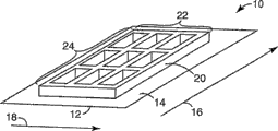
Fig. 1 is the schematic diagram of trellis figure every an embodiment of rib assembly 10.Assembly 10 comprises substrate 12 and places trellis figure 20 on the first type surface 14 of substrate 12.Trellis figure 20 comprises first group of rib 22 arranging by first direction 16 and second group of rib 24 arranging by second direction 18.First group of rib is parallel to each other.Similarly, second group of rib is also parallel to each other.Second group of rib and first group of rib intersect to form a plurality of unit.In at least some preferred embodiments, first group of rib pressed first direction 16 and arranged, and second group of rib arranged by second direction 18, and second direction is vertical substantially with first direction.
Generally speaking, plasma display (PDP) can comprise multiple base component.Be directed in the metacoxal plate assembly (for example assembly 10) that deviates from the beholder and can comprise metacoxal plate (for example substrate 12), this metacoxal plate on its first type surface or in be formed with independently addressable parallel pole (not shown in figure 1).Metacoxal plate can by various compositions for example glass form.Micro-structural (for example the trellis figure 20) is formed on the first type surface of metacoxal plate, and comprises every flank, describedly place between the electrode every flank, and the region separation that will wherein be provided with the fluorescent material of redness (R), green (G) and blueness (B) is opened.PDP also can comprise the prebasal plate assembly, and the prebasal plate assembly comprises glass substrate and one group of independently addressable parallel pole.These preceding electrodes are also referred to as keeps electrode, and itself and rear electrode vertically are orientated, and rear electrode is also referred to as addressing electrode.
In the display of finished product, inert gas can be filled in the zone between prebasal plate assembly and the metacoxal plate assembly.In order to illuminate pixel, the electric field of keeping between electrode and the addressing electrode that is applied to intersection has enough intensity to excite the intert-gas atoms between them.The intert-gas atoms emission UV radiation that is excited, described UV radiation causes red, the green or blue visible light of fluorescent material emission.
Can be preferably, metacoxal plate is transparent glass substrate.Usually, use for PDP, metacoxal plate is made by soda-lime glass, can be randomly, and the essentially no alkali metal of described soda-lime glass.Exist in substrate under the alkali-metal situation, the temperature that reaches during the processing can cause the electrode material migration.This migration can produce conductive path between electrode, thereby makes the adjacent electrode short circuit or produce the electrical interference of not expecting (being called " crosstalking ") between electrode.The glass substrate that prebasal plate is normally transparent, it can have identical with metacoxal plate or approximately uniform thermal coefficient of expansion.
Electrode is the electric conducting material of strip.These electrodes by electric conducting material for example the conduction melt of copper, aluminium or argentiferous form.Especially have under the situation of transparent display floater in hope, these electrodes can also be transparent electric conducting material, for example tin indium oxide.Electrode forms figure on metacoxal plate and prebasal plate.For example, electrode can form parallel band, and the spacing that band is separated by is that about 120 μ m are to 360 μ m, width is that about 50 μ m are to 75 μ m, thickness be about 2 μ m to 15 μ m, its length is crossed over whole effective viewing area, this length range can be from several centimetres to tens centimetres.In some instances, according to the structure of micro-structural, the width of electrode can be narrower or wideer than 75 μ m than 50 μ m.
In certain embodiments, have the width of about 120 μ m usually every flank among the PDP to the height of 140 μ m and about 20 μ m to 75 μ m.Can preferably be complementary every the pitch (number of per unit length) of rib and the pitch of electrode.In other embodiments, can be greater than or less than the pitch of electrode in the mould every the pitch of rib, and mould can stretch so that rib and electrode alignment, as the title of authorizing to people such as Chiu is the U.S. Patent No. 6 of " METHOD FORPRECISE MOLDING AND ALIGNMENT OF STRUCTURES ON ASUB STRATE USING A STRETCHABLE MOLD ", 247,986 B1 are described.
When using the techniques described herein with when forming micro-structural (for example be used for PDP every rib) on the substrate, the curable materials that is used to form micro-structural can be slurry or paste, as the title of authorizing to people such as Dillon is the U.S. Patent No. 6 of " CURABLE SLURRY FOR FORMINGCERAMIC MICROSTRUCTURES ON A SUBSTRA TEU SING AMOLD ", 352,763 B1 are described.Shown in aspect in, the techniques described herein can comprise uses the slurry comprise ceramic powders, curable organic binder bond and diluent, for example U.S. Patent No. 6,352, the slurry described in 763 B1.When binding agent during, can use mould with the slurry setting be arranged on the substrate at its initial uncured state.After cured binders, slurry is at least under the semi-rigid state, thus the shape that can keep it to be molded.The rigid state of this curing is called not slaking state, is called as " not slaking " as the ceramic material that is shaped before being sintered.When slurry is cured, never remove mould in the micro-structural of slaking state.Subsequently, can make the material degreasing of slaking state not and/or fire.When the material of slaking state not is heated to binding agent can be diffused into the temperature of material surface and volatilization the time, degreasing takes place or burnout.Usually, after the degreasing, temperature is elevated to predetermined firing temperature, so that the particle sintering or the fusion of ceramic powders.After firing, this material can be described as fires material.Here, fire micro-structural and be called ceramic microstructures.
Generally speaking, the techniques described herein form micro-structural with mould usually.Mould can be the flexomer sheet, and described flexomer sheet has smooth surface and relative micro-structure surface.Can make mould by the compression molded thermoplastic of conventional tool that use has a microstructure graph.In certain embodiments, mould also can be made by curable materials, and described curable materials is cast and is cured on the thin flexible polymeric film.For example, can use the title of authorizing to people such as Lu is the U.S. Patent No. 5 of " MICROSTRUCTURE-BEARING COMPOSITEPLASTIC ARTICLES AND METHOD OF MAKING ", 175,030, the title of authorizing to Lu is the U.S. Patent No. 5 of " METHOD OF MOLDINGMICROSTRUCTURE BEARING COMPOSITE PLASTIC ARTICLES ", 183,597 and authorize to people's such as Chiu title and form the micro-structural mould for disclosed technology among the U.S. Patent Publication No.2003/0098528 of " METHODFOR FORMING MICROSTRUCTURES ON A SUBSTRATE USING AMOLD ".
Fig. 2 a-e is the schematic diagram of an embodiment of the method for formation micro-structural on substrate.In Fig. 2 a, the device 100 that is used for molded micro-structural on substrate is shown.Device 100 comprises substrate 110, flexible mold 130 and milling roller 140.Substrate 110 can be any substrate as herein described.Flexible mold 130 comprises flexible backing 132 and the micro-structure surface on the first type surface of flexible backing 132 134.Micro-structure surface 134 comprises that rib forms zone 136 and groove forms zone 138.Flexible mold 130 among this embodiment is constructed and arranged to form barrier zones (for example, Fig. 2 e's every rib 124) on substrate 110.
Usually, can provide roller 140 or other device for exerting to come supply pressure, form in the zone 136 with the micro-structure surface 134 interior ribs that force the part curable materials to enter mould 130 to mould 130 and curable materials (for example, the curable materials 120 of Fig. 2 b).
Shown in Fig. 2 b, curable materials 120 is arranged on the first type surface 112 of substrate 110.Usually, use can produce the coating technique of basic uniform coating, and for example scraper type coating, silk screen printing, extrusion coated and oppositely gravure coating (reverse gravure coating) are coated on curable materials 120 on the substrate 110.Curable materials 120 can comprise any suitable a kind of material or multiple material as described herein.
Generally speaking, the varied in thickness of curable materials 120 is no more than 10%.Can be preferably, the varied in thickness of curable materials 120 is no more than 5%.Can be more preferably, the varied in thickness of curable materials 120 is no more than 2%.In one embodiment, the average thickness of curable materials 120 is about 75 μ m.In another embodiment, the average thickness of curable materials 120 can be about 50 μ m.
Can be preferably, hope has the zone (for example zone 116) of the substrate 110 of trellis figure thereon accurately to be determined in advance, and curable materials 120 only is arranged on this zone.The zone (for example, marginal portion 114) that the substrate 110 of curable materials 120 is not set thereon can be used for the processing in the course of processing, and is used at this assembly being used under the situation of PDP being electrically connected.
In Fig. 2 b-c, when when direction 150 is exerted pressure to mould 130, mould 130 is from first end, the 118 contact curable materials 120 of substrate 110.Can use roller 140 to exert pressure, make mould 130 contact curable materials 120 from first end 118 of substrate 110 to mould 130.Can make mould 130 contact curable materials 120 along direction 150 with any suitable contact velocity.Can be preferably, mould 130 is with the basic contact of contact velocity uniformly curable materials 120.In addition, can apply any suitable contact pressure and give mould 130, make this mould contact curable materials.Can preferably apply basic contact pressure uniformly and give mould 130.Make curable materials 120 distortion, thereby the rib of filling the micro-structure surface 134 of flexible mold 130 forms zone 136.Can be preferably, select contact velocity and contact pressure to make curable materials 120 can below the micro-structure surface 134 of flexible mold 130, all not be extruded, thereby in curable materials 120, keep and form regional 138 corresponding trench regions (for example, the trench region 126 of Fig. 2 e) with groove.
When mould 130 contact curable materials 120, curable materials forms trellis figure (for example, the trellis figure 20 of Fig. 1).For example, Fig. 2 d illustrates an embodiment of microstructure elements 160.Microstructure elements 160 comprises substrate 110, flexible mold 130 and curable materials 120.The micro-structure surface 134 of mould 130 is formed at and produces the trellis figure in the curable materials 120.In certain embodiments, the trellis figure comprises first group of rib (for example, first of Fig. 1 group of rib 22) of arranging by first direction (for example, the direction among Fig. 1 16) and (for example presses second direction, the second direction 18 of Fig. 1) second group of rib of Pai Lieing (for example, second of Fig. 1 group of rib 24).In addition, the trellis figure can comprise trench region 126.Shown in Fig. 2 d, rib 124 is included in second group of rib, yet first group of rib is not illustrated.
In Fig. 2 d, curable materials 120 is cured to form rib 124 on the first type surface 112 of substrate 110.According to used binding agent, can be cured material 120 by variety of way.For example, can use one or more solidification equipments that visible light, ultraviolet ray, e bundle radiation or other forms of radiation are provided, perhaps by being heating and curing or coming material is cured from the molten condition cooled and solidified.For radiation curing, radiation can be passed through substrate 110, propagate by mould 130 or by substrate 110 and mould 130.Preferably, selected cure system helps curing materials 120 is adhered to substrate 110.
After the curing materials 120, can remove mould 130 (for example, by mould being rolled onto receiving element for example on the roller).Flexible mold can help to remove mould, because this mould can be shelled back, makes knockout press can concentrate on the less surf zone.Can be preferably, release materials is involved as the coating on the patterned surface of mould, perhaps is included in harden(ing)by itself with in the material that forms the trellis figure.When forming the structure of high aspect ratio, it is more important that release materials becomes.The structure of high aspect ratio makes the demoulding more difficult, and can cause damaging micro-structural.
After removing mould 130, remaining is the substrate 110 that is stained with the micro-structural of a plurality of sclerosis thereon.According to application, this can be a finished product.In other application, such as the substrate with a plurality of micro-structurals, this hardened material comprises the binding agent that preferably is removed by degreasing at high temperature.After the binding agent degreasing or burnouting, the ceramic microstructures of slaking state is not fired so that the glass particle fusion in the material of micro-structural or make the ceramic particle sintering.This has strengthened the strength and stiffness of micro-structural.When the micro-structural densification, in sintering procedure, also can shrink.The micro-structural of firing keeps its position and pitch according to the substrate figure.
For the PDP display application, phosphor material powder is applied between the barrier zones (barrier region) of micro-structural.Substrate can be installed in the display assembly then.This relates to aims at the metacoxal plate with addressing electrode, micro-structural and fluorescent material having the prebasal plate of keeping electrode, makes that to keep electrode vertical with addressing electrode.These comparative electrodes intersect processes area limiting the pixel of display.Then, when substrate bonding during together and in the sealing of its edge, found time in the space between the substrate, and fill inert gas.
Be known as, also can use substrate to form other goods with molded micro-structural.For example, can use molded micro-structural to be formed for capillary channel such as electrophoresis plate etc.In addition, molded micro-structural can be used for plasma scope or produces in other application of light.
When mould contact curable materials, air may be absorbed between the micro-structure surface and curable materials of mould.Form bubble in the micro-structural that the air that is absorbed in like this may form again in curable materials.Can preferably all air that are absorbed in be removed between mould and curable materials.
In this application, " minute bubbles " are meant the bubble of size less than half rib height (or other microstructure features size).It is not preferred having this minute bubbles, but may not can destroy the continuity of rib or other microstructure features, thereby can not reduce functional significantly." air pocket " is meant and is of a size of the high or higher bubble of about half rib.Air pocket can destroy the continuity of rib or other microstructure features, thereby reduces functional significantly.In this application, speech " defective " is meant impaired rib or structure, for example, and the rib that breaks or have the rib of disappearance part, and air pocket.
A kind of method that the air that is absorbed in can be removed is by groove, and these grooves form the micro-structure surface of mould in certain embodiments.For example, Fig. 3 be the flexible mold with micro-structure surface put on curable materials during, the schematic diagram in the path of bubble institute warp when removing bubble.In Fig. 3, the flexible mold (not shown) applies along first direction 212.The trellis figure 220 that forms in curable materials 216 comprises first group of rib 222 arranging by first direction 212.Trellis figure 220 also comprises second group of rib 224 arranging by second direction 214.First bubble 230 is shown schematically in the rib 226 of second group of rib 224.For first bubble 230 that will escape in during applying flexible mold, it must be moved in the rib and the zone between the mould of first group of rib 222, makes its along the direction that applies flexible mold, and promptly first direction 212, extrude from curable materials 216.Qian Yi bubble is schematically illustrated as second bubble 232 like this.
Can help a kind of technology that the air that is absorbed in is removed can be comprised that the rib of control mould micro-structure surface forms some size of zone (being groove).
Fig. 4 a-c is the schematic diagram of flexible mold 300.As further described herein, flexible mold 300 puts on the curable materials along direction 310.Flexible mold 300 has the negative-appearing image of the trellis figure that will form in curable materials, flexible mold 300 will have rib and form the zone, forms regional middle rib assembly at described rib and will have rib.Mould 300 comprises that first group of rib forms the 320 and second groups of ribs in zone and form zone 330.Should understand like this, the rib of mould 300 forms the zone 320 and 330 will form rib in curable materials, and described rib has with respective rib and forms regional essentially identical shape and size.Notice that first group of rib forms zone 320 and arrange by first direction 310, second group of rib forms zone 330 and arranges by second direction 312.In certain embodiments, first group of rib form zone 320 needn't to form zone 330 identical with second group of rib on shape and size.
Shown in Fig. 4 b, each rib that first group of rib forms zone 320 forms the zone and has A/F 322 and bottom width 234.In addition, shown in Fig. 4 c, each rib that second group of rib forms zone 330 forms the zone and has A/F 332 and bottom width 334.In other embodiments, rib forms the zone and can have the A/F that equates with bottom width dimensionally.Perhaps, form the 320 and second groups of ribs in zone for first group of rib and form one or more ribs in one of zone 330 or that these two groups of ribs form in the zone and form the zone, A/F can be greater than bottom width.In addition, the sidewall that rib forms the zone can be any suitable shape, and is for example curved surface shaped, straight, paraboloidal.The sidewall that each rib forms the zone can also have net grain surface or patterned surface.
Each rib that first group of rib forms zone 320 forms the zone and has the degree of depth 328.Similarly, second group of rib each rib of forming zone 330 forms the zone and has the degree of depth 338.Form the 320 or second groups of ribs in zone for first group of rib and form zone 330, the degree of depth that each rib forms the zone can be identical.Perhaps, first group of rib form the degree of depth that each rib that the 320 or second groups of ribs in zone form zone 330 forms the zone may be different.
In addition, first group of rib each rib of forming zone 320 form the zone can have with first group in other rib form the identical shape and size in zone; Perhaps, first group of rib rib of forming zone 320 forms the zone and can have different shape and size.In other embodiments, second group of rib forms zone 330 and can comprise and have identical shaped and rib size forms the zone, and perhaps rib forms the zone and can have different shape and size.
Each rib that first group of rib forms zone 320 forms the zone and has mean breadth, and this mean breadth is half of A/F 322 and bottom width 324 sums.Similarly, to form the mean breadth in zone be half of A/F 332 and bottom width 334 sums to second group of rib each rib of forming zone 330.Each rib that first group of rib forms zone 320 forms the mean breadth that the mean breadth in zone and each rib that second group of rib forms zone 330 form the zone and needn't equate.
First group of rib forms zone 320 to have 326, the second groups of ribs of pitch and forms zone 330 and have pitch 336.First group of rib forms the pitch 326 in zone 320 and pitch 336 that second group of rib forms zone 330 can equate.In certain embodiments, first group of rib pitch 326 of forming zone 320 can be greater than or less than the pitch 336 that second group of rib forms zone 330.
There is Several Factors to influence and from curable materials, removes bubble.For example, the viscosity of curable materials, first group of rib form the removal that the pitch 326 in zone 320 and pitch 336 that second group of rib forms zone 330 may influence bubble.Other parameter also has influence.For example, second group of rib each rib of forming zone 330 mean breadth of forming the zone and first group of rib each rib of forming zone 320 ratio, rib of forming the mean breadth in zone coating thickness of forming the shape in zone and curable materials may influence the formation and the removal of bubble.Another such parameter is (roller) load and pressure that is applied when flexible mold is applied to curing materials and speed or the speed that applies (roller moves).
In order to help prevent bubble to form, can be preferably, the viscosity of curable materials is less than 12,000cps.In addition, can be preferably, first group of rib forms the pitch in zone 320 less than 500 μ m.Can be more preferably, first group of rib forms the pitch in zone less than 300 μ m.
In addition, can be preferably, the ratio that each rib that the mean breadth that each rib that second group of rib forms zone 330 forms the zone and first group of rib form the zone forms the mean breadth in zone is at least 1.5.Though do not wish to be subject to any theory, but be known as, each rib that forms zone 320 with respect to first group of rib forms regional width, second group of rib of broadening forms zone each rib of 330 and forms the zone and can change the pressure drop in each passage during applying flexible mold, makes even littler bubble is escaped by path schematically illustrated among Fig. 3.Those skilled in the art should be understood that, if necessary, each rib that second group of rib formed the zone forms ratio that the mean breadth in zone and each rib that first group of rib forms the zone form the mean breadth in zone and increases to and surpass 1.5, can little by little eliminate more and more littler bubble like this.
In addition, the length in the path that bubble must process in order to escape by path schematically illustrated among Fig. 3 can further influence and remove bubble from curable materials.For example, in certain embodiments, first group of rib forms the distance from bottom while arriving in zone 320 can be less than 150 μ m or greater than 300 μ m.Those skilled in the art should be understood that, if this distance is less than 150 μ m, may be to removing the ratio that each rib that mean breadth that each rib that the effective second group of rib of bubble form zone 330 forms the zone and first group of rib form zone 320 forms regional mean breadth less than 1.5.On the contrary, if this distance less than 300 μ m, may be to effectively removing this required ratio of bubble greater than 1.5.
Another factor that can influence bubble removal is the amount that was arranged on the curable materials on the substrate before flexible mold contact curable materials.As further described herein, curable materials is arranged on a certain zone (for example, the zone 116 of the substrate 110 shown in Fig. 2 b) of substrate, will form trellis rib figure on this zone.The rib that can alternative condition makes the amount of the curable materials extruded below the micro-structure surface of flexible mold be substantially equal to be squeezed into micro-structure surface forms the amount of the curable materials the zone.The first group rib corresponding with first group of rib arranging by first direction forms the zone provides air duct, and bubble can be escaped from by this air duct.
Yet,, can before the feeding flexible mold, form a pile curable materials if the amount of the curable materials of extruding substantially exceeds the amount that rib forms the curable materials the zone that is squeezed into below the micro-structure surface of flexible mold.This causes the situation of " paste overflows ".When setting up heap, one or more ribs that second group of rib forms zone (for example second of Fig. 4 a group of rib forms zone 330) form the zone and are filled disorderly.First group of rib forms the zone provides air duct, and bubble can be escaped from (for example, referring to Fig. 3) by this air duct.Yet the one or more ribs that form the zone when second group of rib form the zone when being filled disorderly, and it is blocked to form this air duct that the zone provides by first group of rib; Thereby some bubbles may not can be escaped from fully.
The amount that not only is arranged on the curable materials on the substrate influences bubble removal, and the viscosity of curable materials and the speed that moves by roller applied pressure or load and roller also may influence bubble removal.For example, the viscosity of too low curable materials also may cause paste to overflow.
Example
Example 1
Required size according to the trellis graphic assembly that will make prepares metal mold.Metal mold has micro-structure surface, and this micro-structure surface has that first group of rib arranging by first direction forms the zone and second group of rib arranging by second direction forms the zone, described second direction and described first direction perpendicular.It is 300 μ m that first group of rib forms regional pitch.The height that each rib that first group of rib forms the zone forms the zone is 208 μ m, and A/F is 55 μ m, and bottom width is 115 μ m.The size that these ribs form the zone will form the rib that cone angle is 82 degree.This cone angle is the angle in the rib bottom.Rib with equal A/F and bottom width forms the zone and will form the rib that cone angle is 90 degree.It is 500 μ m that second group of rib forms regional pitch.The height that each rib forms the zone is 208 μ m, and A/F is 37 μ m, and bottom width is 160 μ m, and this will produce the rib cone angle of 75 degree.
Aliphatic urethane acrylate oligomer (the Photomer6010 for preparing 99% weight
TM, make by Henkel company) and the 2-hydroxy-2-methyl-1-phenyl-propane-1-ketone of 1% weight (Darocure 1173
TM, make by Ciba-Gigy company) mixture as light trigger.The mixture that exceeds complete filling mould micro-structure surface aequum slightly is arranged between PET film and the metal mold.This mixture was cured by the radiation that is exposed to wavelength 300-400nm in 30 seconds.The urethane acrylate polymer of Gu Huaing is attached on the PET film forcefully thus, and peels off from metal mold to obtain flexible, transparent plastics mould with the PET film.Rib in this flexible mold form the zone have with metal mold in rib form the identical shape and size in zone.
The preparation ceramic paste is to use as curable materials in method of moulding.With 21.0g bisphenol-A diglycidyl ether type dimethylacrylate (deriving from Kyoeisha Chemical company); 9.0g dimethacrylate triethyleneglycol ester (deriving from Wako Pure ChemicalIndustries company); 30.0g as 1 of diluent; 3-butanediol (deriving from Wako PureChemical Industries company); 0.3g as two (2 of initator; 4; the 6-trimethylbenzoyl)-(Irgacure 819 for phenylphosphorous acid oxide (phenylphospheneoxide); make by Ciba-Geigy company); 3.0g as the phosphate type polyoxy alkyl polyols (POCA) (phosphated polyoxyalkyl polyol) of surfactant and the mixture (RFW-030 of 180.0g glass dust and ceramic particle; make by Asahi Glass company) mix, obtain photo curable ceramic paste.This paste viscosity is 6000cps (under 22 ℃, measuring axle (spindle) with the tachometric survey of 20rpm with No.5 on Brookfield viscometer).
Ceramic paste is coated with 200 μ m on glass substrate thick, then, uses roller that flexible mold is applied on this paste along first direction.Then, this assembly is exposed to following 30 seconds of the radiation of wavelength 400-500nm to solidify this paste.Along first direction this flexible mold is peeled off from substrate.Make substrate then and solidify the rib assembly 550 ℃ of following sintering 1 hour to burn the organic moiety of these ribs.After the sintering, use light microscope that these ribs are assessed.The successional air pocket that is enough to destroy significantly rib in the infringement of rib or the rib is regarded as defective.Sometimes, cross rib just above observe very little bubble.These minute bubbles are similar on the magnitude high less than rib, so they can not destroy the continuity of rib significantly.On this sample, do not observe defective.On this sample, observe minute bubbles.
Defect rank in this example and other example is defined as the ratio of the rib hop count order in the defective number that is detected and the second direction rib group in microscopical visible range (diameter 7.5mm).On seven zones of selecting at random of sample, carry out this measurement, and report these seven results' mean value.The defect rank of example 1 is 0.0%.
Example 2 and 3
Described according to example 1, make flexible mold.By changing the viscosity that solids content (glass dust and ceramic particle) changes paste.In example 2, solids content is 90.0g, and in example 3, solids content is 145.0g.All other components aspect type and loading with example 1 in identical.For example 2, paste viscosity is 1800cps, and for example 3, paste viscosity is 4800cps.
Make trellis figure rib assembly according to the method identical with example 1.Measure defect rank by microscopy.Example 2 and 3 defect rank are 0.0%.In these samples, observe minute bubbles.
Comparative example 1 and 2
Described according to example 1, make flexible mold.By changing the viscosity that solids content (glass dust and ceramic particle) changes paste.In comparative example 1, solids content is 220.0g, and in comparative example 2, solids content is 270.0g.All other components aspect type and loading with example 1 in identical.For comparative example 1, paste viscosity is 12,600cps, and for comparative example 2, paste viscosity is 27,300cps.
Make trellis figure rib assembly according to the method identical with example 1.Measure defect rank by microscopy.For comparative example 1, defect rank is 0.1%, and for comparative example 2, defect rank is 3.3%.In these samples, also observe minute bubbles.
Comparative example 3
Except the first direction of mould and second direction are put upside down, described according to example 1, make flexible mold and ceramic paste.Therefore, the pitch of first direction is 500 μ m.Paste viscosity is 6000cps.Make trellis figure rib assembly according to the method identical with example 1.Measure defect rank by microscopy.In this sample, observe a lot of defectives.
All crossing members (cross member) all have defective, and the defect rank in this explanation comparative example 3 is 100%.In this sample, also observe minute bubbles.
Example 4
Use and example 1 identical materials, preparation has the flexiplast mould of trellis figure micro-structure surface.
Micro-structure surface in this mould is corresponding with the rib with following size.The pitch of the rib of first group of rib is 300 μ m, and height is 200 μ m, and A/F is 50 μ m, and bottom width is 100 μ m.The pitch of the rib of second group of rib is 500 μ m, and height is 200 μ m, and A/F is 150 μ m, and bottom width is 220 μ m.
Therefore, the mean breadth of each rib of first group of rib is (50+100)/2=75, and the mean breadth of each rib of second group of rib is (150+220)/2=185.So the mean breadth of each rib of second group of rib is 185/75 or about 2.5 with the ratio of the mean breadth of each rib of first group of rib.
The preparation ceramic paste is to use as curable materials in method of moulding.With 21.0g bisphenol-A diglycidyl ether type dimethylacrylate (deriving from Kyoeisha Chemical company); 9.0g dimethacrylate triethyleneglycol ester (deriving from Wako Pure ChemicalIndustries company); 30.0g as 1 of diluent; 3-butanediol (deriving from Wako PureChemical Industries company); 0.2g as two (2 of initator; 4; the 6-trimethylbenzoyl)-(Irgacure 819 for phenylphosphorous acid oxide (phenylphospheneoxide); make by Ciba-Geigy company); 1.5g phosphate type polyoxy alkyl polyols (POCA) (phosphated polyoxyalkyl polyol) and 1.5g neopelex (NeoPelex #25 as surfactant; make by Kao company); and the mixture (RFW-030 of 270.0g glass dust and ceramic particle; make by Asahi Glass company) mix, obtain photo curable ceramic paste.This paste viscosity is 7300cps (under 22 ℃, measuring axle with the tachometric survey of 20rpm with No.5 on Brookfield viscometer).
It is thick with blade coating machine this ceramic paste to be coated with 130 μ m on glass substrate, then, uses rubber rollers that flexible mold is applied on this paste along first direction.
Then, this assembly is exposed to following 30 seconds of the radiation of wavelength 400-500nm to solidify this paste.Along first direction this flexible mold is peeled off from substrate.
Size by near the bubble of the microscopy rib top of measuring second group of rib on 18 points.This average bubble size is summarized in the table 1.In example 4, do not observe defective and minute bubbles.
Example 5 and 6
Preparation has the flexiplast mould that the rib different with example 4 forms region shape.
Describe below with these ribs and form the corresponding rib shape of region shape.
Example 5:
The pitch of the rib of first group of rib is 300 μ m, and height is 200 μ m, and A/F is 50 μ m, and bottom width is 100 μ m.The pitch of the rib of second group of rib is 500 μ m, and height is 200 μ m, and A/F is 125 μ m, and bottom width is 190 μ m.
Therefore, the mean breadth of each rib of first group of rib is (50+100)/2=75, and the mean breadth of each rib of second group of rib is (125+190)/2=157.5.So the mean breadth of each rib of second group of rib is 157.5/75=2.1 with the ratio of the mean breadth of each rib of first group of rib.
Example 6:
The pitch of the rib of first group of rib is 300 μ m, and height is 200 μ m, and A/F is 50 μ m, and bottom width is 100 μ m.The pitch of the rib of second group of rib is 500 μ m, and height is 200 μ m, and A/F is 100 μ m, and bottom width is 170 μ m.
Therefore, the mean breadth of each rib of first group of rib is (50+100)/2=75, and the mean breadth of each rib of second group of rib is (100+170)/2=135.So the mean breadth of each rib of second group of rib is 135/75=1.8 with the ratio of the mean breadth of each rib of first group of rib.
As described in example 4, use mould to form trellis figure rib.Size by near the bubble of the microscopy rib top of measuring second group of rib on 18 points.This average bubble size is summarized in the table 1.In example 5 and 6, do not observe defective and minute bubbles.
Example 7 and 8
Preparation has the flexiplast mould that the rib different with example 4 forms region shape.
Describe below with these ribs and form the corresponding rib shape of region shape.
Example 7:
The pitch of the rib of first group of rib is 300 μ m, and height is 200 μ m, and A/F is 50 μ m, and bottom width is 100 μ m.The pitch of the rib of second group of rib is 500 μ m, and height is 200 μ m, and A/F is 75 μ m, and bottom width is 140 μ m.
Therefore, the mean breadth of each rib of first group of rib is (50+100)/2=75, and the mean breadth of each rib of second group of rib is (75+140)/2=107.5.So the mean breadth of each rib of second group of rib is 107.5/75=1.4 with the ratio of the mean breadth of each rib of first group of rib.
Example 8:
The pitch of the rib of first group of rib is 300 μ m, and height is 200 μ m, and A/F is 60 μ m, and bottom width is 120 μ m.The pitch of the rib of second group of rib is 500 μ m, and height is 200 μ m, and A/F is 60 μ m, and bottom width is 110 μ m.
Therefore, the mean breadth of each rib of first group of rib is (60+120)/2=90, and the mean breadth of each rib of second group of rib is (60+110)/2=85.So the mean breadth of each rib of second group of rib is 85/90=0.94 with the ratio of the mean breadth of each rib of first group of rib.
As described in example 4, use mould to form trellis figure rib.Size by near the bubble of the microscopy rib top of measuring second group of rib on 18 points.This average bubble size is summarized in the table 1.The mean size of the bubble in the example 7 and 8 is respectively 18 μ m and 25 μ m.Yet, in these samples, do not observe defective.
Table 1
Ratio bubble size
| Example 4 | 2.5 | 0 micron |
| Example 5 | 2.1 | 0 micron |
| Example 6 | 1.8 | 0 micron |
| Example 7 | 1.4 | 18 microns |
| Example 8 | 0.9 | 25 microns |
Example 9
Required size by trellis graphic assembly to be made prepares metal mold.Metal mold has micro-structure surface, and this micro-structure surface has that first group of rib arranging by first direction forms the zone and second group of rib arranging by second direction forms the zone, second direction and first direction perpendicular.It is 300 μ m that first group of rib forms regional pitch.The height that each rib that first group of rib forms the zone forms the zone is 200 μ m, and A/F is 60 μ m, and bottom width is 120 μ m.The pitch that each rib that second group of rib forms the zone forms the zone is 500 μ m, and height is 200 μ m, and A/F is 40 μ m, and bottom width is 160 μ m, thereby produces the rib cone angles of 75 degree.
Aliphatic urethane acrylate oligomer (the Photomer6010 for preparing 99% weight
TM, make by Henkel company) and the 2-hydroxy-2-methyl-1-phenyl-propane-1-ketone of 1% weight (Darocure 1173
TM, make by Ciba-Gigy company) mixture as light trigger.The mixture that exceeds complete filling mould micro-structural aequum slightly is arranged between PET film and the metal mold.This mixture was cured by the radiation that is exposed to wavelength 300-400nm in 30 seconds.The urethane acrylate polymer of Gu Huaing is attached on the PET film forcefully thus, and peels off from metal mold to obtain flexible, transparent plastics mould with the PET film.Groove in this flexible mold has and identical shape and size of rib in the metal mold.
The preparation ceramic paste is to use as curable materials in method of moulding.With 21.0g bisphenol-A diglycidyl ether type dimethylacrylate (deriving from Kyoeisha Chemical company); 9.0g dimethacrylate triethyleneglycol ester (deriving from Wako Pure ChemicalIndustries company); 30.0g as 1 of diluent; 3-butanediol (deriving from Wako PureChemical Industries company); 0.2g as two (2 of initator; 4; the 6-trimethylbenzoyl)-(Irgacure 819 for phenylphosphorous acid oxide (phenylphospheneoxide); make by Ciba-Geigy company); 1.5g phosphate type polyoxy alkyl polyols (POCA) (phosphated polyoxyalkyl polyol) and 1.5g neopelex (NeoPelex #25 as surfactant; make by Kao company); and the mixture (RFW-030 of 270.0g glass dust and ceramic particle; make by Asahi Glass company) mix, obtain photo curable ceramic paste.This paste viscosity is 7300cps (under 22 ℃, measuring axle with the tachometric survey of 20rpm with No.5 on Brookfield viscometer).
It is thick with blade coating machine this ceramic paste to be coated with 110 μ m on glass substrate.Spreading area is the rectangle of the 950 * 540mm corresponding with the trellis graphics field of mould.Use the roller of 30kg, diameter 200mm, flexible mold is applied on the paste layer of 110 micron thickness along first direction with the speed of 42mm/s.Because do not provide additional load, be 30kg/950mm or about 0.032kg/mm so give the total load of mould to mould.Then, this assembly is exposed to following 30 seconds of the radiation of wavelength 400-500nm to solidify this paste.Flexible mold is peeled off from substrate along first direction.
The difference that applies the paste spreading area before the flexible mold and apply the paste spreading area after the flexible mold by measurement obtains owing to apply the amount that paste that step produces overflows.The sample of example 9 does not show difference before applying flexible mold and in the paste spreading area afterwards, this shows that the condition of example 9 can not produce the situation of " paste overflows ".
After removing mould, the assembly that makes substrate and trellis figure rib is 550 ℃ of following sintering 1 hour, to burn the organic moiety of these ribs.
After the sintering, measure defective by the light microscope method.Defective (is not all observed in whole zone at the sample of example 9 on 950 * 540mm).In this sample, observe minute bubbles.
Example 10 and 11
Described according to example 9, make flexiplast mould and photo curable ceramic paste.It is thick with blade coating machine this ceramic paste to be coated with 110 μ m on glass substrate.Spreading area is the rectangle of the 950 * 540mm corresponding with the trellis graphics field of mould.Then, flexible mold is applied on the paste layer of 110 micron thickness along first direction.For example 10, use the roller of 30kg, diameter 200mm with the speed of 20mm/s.For example 11, use the roller of 100kg, diameter 200mm with the speed of 42mm/s.Because do not provide additional load to mould, so for example 10, giving the total load of mould is 30kg/950mm or about 0.032kg/mm, for example 11, giving the total load of mould is 100kg/950mm or about 0.105kg/mm.Then, this assembly is exposed to following 30 seconds of the radiation of wavelength 400-500nm to solidify this paste.Flexible mold is peeled off from substrate along first direction.
The difference that applies the paste spreading area before the flexible mold and apply the paste spreading area after the flexible mold by measurement obtains owing to apply the amount that paste that step produces overflows.Example 10 and 11 sample do not show difference before applying flexible mold and in the paste spreading area afterwards, this shows that the condition of example 10 and 11 can not produce the situation of " paste overflows ".
After removing mould, the assembly that makes substrate and trellis figure rib is 550 ℃ of following sintering 1 hour, to burn the organic moiety of these ribs.
After the sintering, measure defective by the light microscope method.Defective (is not all observed in whole zone at the sample of example 10 and 11 on 950 * 540mm).In this sample, observe minute bubbles.
Comparative example 4
Described according to example 9, make the flexiplast mould.Reduce paste viscosity by the content that reduces RFW-030 in the paste.Use 180.0g RFW-030 to replace used 270.0g RFW-030 in the example 9.The content of other composition of all in the paste is identical.Viscosity is 3000cps.
It is thick with blade coating machine this ceramic paste to be coated with 110 μ m on glass substrate.Spreading area is the rectangle of the 950 * 540mm corresponding with the trellis graphics field of mould.Then, use the roller of 100kg, diameter 200mm, flexible mold is applied on the paste layer of 110 micron thickness along first direction with the speed of 20mm/s.Because do not provide additional load, be 100kg/950mm or about 0.105kg/mm so give the total load of mould to mould.Then, this assembly is exposed to following 30 seconds of the radiation of wavelength 400-500nm to solidify this paste.Flexible mold is peeled off from substrate along first direction.
The difference that applies the paste spreading area before the flexible mold and apply the paste spreading area after the flexible mold by measurement obtains owing to apply the amount that paste that step produces overflows.The sample of comparative example 4 shows before applying flexible mold and there is difference greater than 50mm in paste spreading area afterwards on first direction, and this shows that the condition of comparative example 4 can be called as " paste overflows " condition.
After removing mould, the assembly that makes substrate and trellis figure rib is 550 ℃ of following sintering 1 hour, to burn the organic moiety of these ribs.
After the sintering, measure defective by the light microscope method.Whole zone at the sample of comparative example 4 (is observed on 950 * 540mm) and is surpassed 100 defectives.In this sample, also observe minute bubbles.
All lists of references and publication that this paper quoted are all incorporated among the present invention by reference.Exemplary embodiment of the present invention has been discussed, and with reference within the scope of the invention various may the distortion.For those skilled in the art, without departing from the scope of the invention, these and other distortion in the present invention and to revise will be conspicuous should be understood like this, and the present invention is not limited to the exemplary embodiment that this paper sets forth.Therefore, the claim that is provided below the present invention only is subjected to limits.
Claims (11)
1. method that on substrate, forms micro-structural, this method comprises:
Curable materials is arranged on the substrate, and wherein, described curable materials has less than 12, the viscosity of 000cps;
From first end of described substrate, described curable materials is contacted with flexible mold, advance by basic contact velocity uniformly and apply basic contact pressure uniformly along first direction;
Use described mould that described curable materials is formed the trellis figure, wherein, described trellis figure comprises first group of substantially parallel rib and second group of substantially parallel rib, described second group of substantially parallel rib intersects with described first group of substantially parallel rib, and the ratio of the mean breadth of each rib in the mean breadth of each rib in described second group of substantially parallel rib and the described first group of substantially parallel rib is at least 1.5, and the pitch of wherein said first group of substantially parallel rib is less than 500 μ m;
Described curable materials is solidified; And
Remove described mould.
2. method according to claim 1, wherein, described first group of substantially parallel rib pressed first direction and arranged, and described second group of substantially parallel rib arranged by second direction, described second direction and described first direction perpendicular.
3. method according to claim 1 also is included in to remove and fires described curable materials after the described mould.
4. method according to claim 3, wherein, the described curable materials after firing does not have impaired rib or structure basically and is not of a size of the high or higher bubble of half rib basically.
5. method according to claim 1, wherein, the pitch of described first group of substantially parallel rib is less than 300 μ m.
6. method according to claim 1, wherein, a plurality of ribs in described first group of substantially parallel rib connect by middle trench region, and wherein, described middle trench region has basic center thickness uniformly.
7 methods according to claim 1, wherein, a plurality of ribs in described second group of substantially parallel rib connect by middle trench region, and wherein, described middle trench region has basic center thickness uniformly.
8. method according to claim 1, wherein, described curable materials comprises ceramic material.
9. method according to claim 1 wherein, contacts described curable materials and is included in launches described flexible mold when first end of described substrate begins to contact described curable materials.
10. method according to claim 9 wherein, is removed described flexible mold and is comprised described flexible mold is rolled onto on the receiving element.
11. a microstructure elements comprises:
Substrate;
Flexible mold, described flexible mold has micro-structure surface, and described micro-structure surface is surperficial relative with described substrate;
Curable materials, described curable materials places between the micro-structure surface of described substrate and described flexible mold, wherein, the described micro-structure surface of described mould is formed at and produces the trellis figure in the described curable materials, wherein said trellis figure comprises first group of substantially parallel rib and second group of substantially parallel rib, described second group of substantially parallel rib intersects with described first group of substantially parallel rib, and the ratio of the mean breadth of each rib in the mean breadth of each rib in described second group of substantially parallel rib and the described first group of substantially parallel rib is at least 1.5, the pitch of wherein said first group of substantially parallel rib is less than 500 μ m, the viscosity of wherein said curable materials is less than 12,000cps, and wherein said curable materials is not of a size of the high or higher bubble of half rib basically.
Applications Claiming Priority (2)
| Application Number | Priority Date | Filing Date | Title |
|---|---|---|---|
| US10/698,200 | 2003-10-31 | ||
| US10/698,200 US7288013B2 (en) | 2003-10-31 | 2003-10-31 | Method of forming microstructures on a substrate and a microstructured assembly used for same |
Publications (2)
| Publication Number | Publication Date |
|---|---|
| CN1875448A CN1875448A (en) | 2006-12-06 |
| CN100521038C true CN100521038C (en) | 2009-07-29 |
Family
ID=34550565
Family Applications (1)
| Application Number | Title | Priority Date | Filing Date |
|---|---|---|---|
| CNB2004800322279A Expired - Fee Related CN100521038C (en) | 2003-10-31 | 2004-10-08 | Method of forming microstructures on a substrate and a microstructured assembly used for same |
Country Status (8)
| Country | Link |
|---|---|
| US (2) | US7288013B2 (en) |
| EP (1) | EP1685074A2 (en) |
| JP (1) | JP2007513467A (en) |
| KR (1) | KR20060096069A (en) |
| CN (1) | CN100521038C (en) |
| CA (1) | CA2543518A1 (en) |
| TW (1) | TW200519415A (en) |
| WO (1) | WO2005042427A2 (en) |
Families Citing this family (26)
| Publication number | Priority date | Publication date | Assignee | Title |
|---|---|---|---|---|
| US6761607B2 (en) * | 2000-01-11 | 2004-07-13 | 3M Innovative Properties Company | Apparatus, mold and method for producing substrate for plasma display panel |
| US7288013B2 (en) * | 2003-10-31 | 2007-10-30 | 3M Innovative Properties Company | Method of forming microstructures on a substrate and a microstructured assembly used for same |
| JP2005288933A (en) * | 2004-04-01 | 2005-10-20 | Three M Innovative Properties Co | Flexible molding die and its manufacturing method |
| JP4647258B2 (en) * | 2004-07-29 | 2011-03-09 | 株式会社日立製作所 | Molding material transfer method, substrate structure |
| WO2006026142A1 (en) * | 2004-08-26 | 2006-03-09 | 3M Innovative Properties Company | Method of forming microstructures with a discrete mold provided on a roller |
| JP2008511122A (en) * | 2004-08-26 | 2008-04-10 | スリーエム イノベイティブ プロパティズ カンパニー | Method for forming microstructures in multiple separate molds |
| CN101010772A (en) * | 2004-08-26 | 2007-08-01 | 3M创新有限公司 | Method of forming microstructures with a template |
| JP2006147584A (en) * | 2004-11-23 | 2006-06-08 | Lg Electronics Inc | Plasma display panel |
| US20070018363A1 (en) * | 2005-07-20 | 2007-01-25 | 3M Innovative Properties Company | Methods of aligning mold and articles |
| US20070018348A1 (en) * | 2005-07-20 | 2007-01-25 | 3M Innovative Properties Company | Aligned mold comprising support |
| TWI265543B (en) * | 2005-11-22 | 2006-11-01 | Marketech Int Corp | The manufacturing method of the shadow mask of an opposed discharge plasma display panel |
| JP2007147829A (en) * | 2005-11-25 | 2007-06-14 | Brother Ind Ltd | Method for manufacturing partition wall and substrate in electrophoretic display medium, and electrophoretic display medium |
| US20070126158A1 (en) * | 2005-12-01 | 2007-06-07 | 3M Innovative Properties Company | Method of cleaning polymeric mold |
| KR100761137B1 (en) * | 2006-01-05 | 2007-09-21 | 엘지전자 주식회사 | Plasma Display Panel |
| US20080036114A1 (en) * | 2006-08-14 | 2008-02-14 | 3M Innovative Properties Company | Mold having surface modified non-molding regions |
| JP2008085323A (en) * | 2006-08-31 | 2008-04-10 | National Institute Of Advanced Industrial & Technology | Transparent electrode substrate for solar cell |
| US20080093776A1 (en) * | 2006-10-05 | 2008-04-24 | 3M Innovative Properties Company | Method of molding ultraviolet cured microstructures and molds |
| KR20100026454A (en) * | 2008-08-29 | 2010-03-10 | 삼성전기주식회사 | Manufacturing method of ceramic green sheet and manufacturing method of multilayer ceramic circuit board |
| WO2010030032A1 (en) * | 2008-09-12 | 2010-03-18 | 日本碍子株式会社 | Manufacturing method for three-dimensional molded parts |
| WO2011068884A2 (en) * | 2009-12-01 | 2011-06-09 | University Of Massachusetts | A system for producing patterned silicon carbide structures |
| TW201341211A (en) * | 2012-04-12 | 2013-10-16 | Inhon Internat Co Ltd | Method of fabricating in-mold release film |
| CN110908238A (en) | 2012-09-06 | 2020-03-24 | Ev 集团 E·索尔纳有限责任公司 | Structural stamp, apparatus and method for imprinting |
| US8936461B2 (en) * | 2013-03-14 | 2015-01-20 | Dominic Palazzolo | Transfer device and method of using |
| DE102013107909B4 (en) * | 2013-07-24 | 2015-04-09 | Schott Ag | Method and system for embossing a structure on a substrate coated with a lacquer |
| DE102014113854A1 (en) * | 2014-09-24 | 2016-03-24 | Ev Group E. Thallner Gmbh | Method for producing a glass optical element |
| JP7325533B2 (en) | 2019-11-28 | 2023-08-14 | 京セラ株式会社 | mirror |
Family Cites Families (33)
| Publication number | Priority date | Publication date | Assignee | Title |
|---|---|---|---|---|
| US5352478A (en) | 1982-02-10 | 1994-10-04 | Dai Nippon Insatsu Kabushiki Kaisha | Plasma display panel and method of manufacturing same |
| JP2774279B2 (en) | 1988-05-12 | 1998-07-09 | 大日本印刷株式会社 | Manufacturing method of lens sheet |
| US5175030A (en) | 1989-02-10 | 1992-12-29 | Minnesota Mining And Manufacturing Company | Microstructure-bearing composite plastic articles and method of making |
| US5183597A (en) | 1989-02-10 | 1993-02-02 | Minnesota Mining And Manufacturing Company | Method of molding microstructure bearing composite plastic articles |
| EP0382260B1 (en) | 1989-02-10 | 1995-05-03 | Dai Nippon Insatsu Kabushiki Kaisha | Plasma display panel and method of manufacturing same |
| JP2837875B2 (en) | 1989-06-06 | 1998-12-16 | 大日本印刷株式会社 | Manufacturing method of lens sheet |
| JP3114988B2 (en) | 1990-09-21 | 2000-12-04 | 大日本印刷株式会社 | Lens sheet manufacturing equipment |
| US5601468A (en) | 1991-10-14 | 1997-02-11 | Dai Nippon Printing Co., Ltd. | Plasma display panel and method for forming fluorescent screens of the same |
| JP3591910B2 (en) * | 1995-03-30 | 2004-11-24 | 大日本印刷株式会社 | Manufacturing method of cell barrier for plasma display panel |
| JP3791022B2 (en) | 1995-06-26 | 2006-06-28 | 旭硝子株式会社 | Method for forming partition wall on substrate |
| JPH09283017A (en) | 1996-04-11 | 1997-10-31 | Matsushita Electric Ind Co Ltd | Gas discharge panel, manufacture thereof, and device for manufacturing gas discharge panel |
| US5853446A (en) | 1996-04-16 | 1998-12-29 | Corning Incorporated | Method for forming glass rib structures |
| TW353762B (en) | 1996-10-21 | 1999-03-01 | Dainippon Printing Co Ltd | Transfer sheet, and pattern-forming method |
| JPH11339668A (en) * | 1998-05-27 | 1999-12-10 | Toray Ind Inc | Plasma display and its manufacture |
| JPH11213874A (en) * | 1998-01-28 | 1999-08-06 | Hitachi Chem Co Ltd | Manufacture of barrier for plasma display panel |
| JP2000021303A (en) | 1998-07-06 | 2000-01-21 | Hitachi Ltd | Gas discharge type plane display device and manufacture therefor |
| JP2000137442A (en) | 1998-08-26 | 2000-05-16 | Sumitomo Chem Co Ltd | Optical filter for display |
| US6352763B1 (en) | 1998-12-23 | 2002-03-05 | 3M Innovative Properties Company | Curable slurry for forming ceramic microstructures on a substrate using a mold |
| US6247986B1 (en) | 1998-12-23 | 2001-06-19 | 3M Innovative Properties Company | Method for precise molding and alignment of structures on a substrate using a stretchable mold |
| EP1216482B1 (en) | 1999-09-13 | 2007-06-06 | 3M Innovative Properties Company | Barrier rib formation on substrate for plasma display panels |
| JP4082545B2 (en) * | 2000-01-11 | 2008-04-30 | スリーエム イノベイティブ プロパティズ カンパニー | Apparatus, mold and method for manufacturing substrate for plasma display panel |
| US6761607B2 (en) | 2000-01-11 | 2004-07-13 | 3M Innovative Properties Company | Apparatus, mold and method for producing substrate for plasma display panel |
| JP3532146B2 (en) | 2000-08-09 | 2004-05-31 | 住友ゴム工業株式会社 | Transparent electromagnetic wave shielding member and method of manufacturing the same |
| JP2003132805A (en) * | 2001-08-14 | 2003-05-09 | Sony Corp | Plasma display device |
| US7033534B2 (en) | 2001-10-09 | 2006-04-25 | 3M Innovative Properties Company | Method for forming microstructures on a substrate using a mold |
| US7176492B2 (en) | 2001-10-09 | 2007-02-13 | 3M Innovative Properties Company | Method for forming ceramic microstructures on a substrate using a mold and articles formed by the method |
| JP4326190B2 (en) | 2002-07-10 | 2009-09-02 | スリーエム イノベイティブ プロパティズ カンパニー | Flexible mold and manufacturing method thereof |
| JP3986386B2 (en) | 2002-07-17 | 2007-10-03 | スリーエム イノベイティブ プロパティズ カンパニー | Manufacturing method of fine structure |
| JP4179853B2 (en) | 2002-11-13 | 2008-11-12 | スリーエム イノベイティブ プロパティズ カンパニー | Flexible mold and method for producing fine structure |
| US20060225463A1 (en) * | 2003-07-31 | 2006-10-12 | Takaki Sugimoto | Master mold for duplicating fine structure and production method thereof |
| JP2005066836A (en) * | 2003-08-22 | 2005-03-17 | Three M Innovative Properties Co | Flexible mold, its manufacturing method and fine structure manufacture method |
| US7288013B2 (en) * | 2003-10-31 | 2007-10-30 | 3M Innovative Properties Company | Method of forming microstructures on a substrate and a microstructured assembly used for same |
| JP2005288933A (en) * | 2004-04-01 | 2005-10-20 | Three M Innovative Properties Co | Flexible molding die and its manufacturing method |
-
2003
- 2003-10-31 US US10/698,200 patent/US7288013B2/en not_active Expired - Fee Related
-
2004
- 2004-10-08 EP EP04816912A patent/EP1685074A2/en not_active Withdrawn
- 2004-10-08 WO PCT/US2004/033170 patent/WO2005042427A2/en active Application Filing
- 2004-10-08 CA CA002543518A patent/CA2543518A1/en not_active Abandoned
- 2004-10-08 JP JP2006538030A patent/JP2007513467A/en active Pending
- 2004-10-08 CN CNB2004800322279A patent/CN100521038C/en not_active Expired - Fee Related
- 2004-10-08 KR KR1020067008238A patent/KR20060096069A/en not_active Application Discontinuation
- 2004-10-29 TW TW093133059A patent/TW200519415A/en unknown
-
2007
- 2007-08-29 US US11/846,784 patent/US20110039040A9/en not_active Abandoned
Also Published As
| Publication number | Publication date |
|---|---|
| US20110039040A9 (en) | 2011-02-17 |
| WO2005042427A3 (en) | 2005-07-07 |
| US20090061116A1 (en) | 2009-03-05 |
| KR20060096069A (en) | 2006-09-05 |
| JP2007513467A (en) | 2007-05-24 |
| US7288013B2 (en) | 2007-10-30 |
| WO2005042427A2 (en) | 2005-05-12 |
| US20050093202A1 (en) | 2005-05-05 |
| EP1685074A2 (en) | 2006-08-02 |
| CN1875448A (en) | 2006-12-06 |
| TW200519415A (en) | 2005-06-16 |
| CA2543518A1 (en) | 2005-05-12 |
Similar Documents
| Publication | Publication Date | Title |
|---|---|---|
| CN100521038C (en) | Method of forming microstructures on a substrate and a microstructured assembly used for same | |
| CN100575035C (en) | Flexible mould and method thereof | |
| US7033534B2 (en) | Method for forming microstructures on a substrate using a mold | |
| CN1230856C (en) | Method for precise molding and alignment of structures on substrate using stretchable mold | |
| CN101160639B (en) | Method of reusing flexible mold and microstructure precursor composition | |
| CN100481302C (en) | Method for forming ceramic microstructures on a substrate using a mold and articles formed by the method | |
| US20060043637A1 (en) | Methods of forming barrier rib microstructures with a mold | |
| CN1728319A (en) | Molding material transfer method and substrat structure | |
| US20060043634A1 (en) | Method of forming microstructures with a discrete mold provided on a roller | |
| US7670543B2 (en) | Method of forming microstructures with a template | |
| CN101228607A (en) | Methods of aligning mold and articles | |
| JP2001035390A (en) | Powdery barrier rib baking material and barrier rib forming method for discharge display device | |
| CN101010771A (en) | Method of forming microstructures with multiple discrete molds | |
| KR100262746B1 (en) | A manufacturing method of plasma display panel using metallic mould | |
| JP2006147228A (en) | Method and device for manufacturing plasma display panel | |
| CN101501809A (en) | Mold having surface modified non-molding regions | |
| CN101010770A (en) | Method of forming barrier rib microstructures with a mold |
Legal Events
| Date | Code | Title | Description |
|---|---|---|---|
| C06 | Publication | ||
| PB01 | Publication | ||
| C10 | Entry into substantive examination | ||
| SE01 | Entry into force of request for substantive examination | ||
| C14 | Grant of patent or utility model | ||
| GR01 | Patent grant | ||
| C17 | Cessation of patent right | ||
| CF01 | Termination of patent right due to non-payment of annual fee |
Granted publication date: 20090729 Termination date: 20111008 |