CN100522109C - Prosthetic foot with tunable performance - Google Patents
Prosthetic foot with tunable performance Download PDFInfo
- Publication number
- CN100522109C CN100522109C CNB028110625A CN02811062A CN100522109C CN 100522109 C CN100522109 C CN 100522109C CN B028110625 A CNB028110625 A CN B028110625A CN 02811062 A CN02811062 A CN 02811062A CN 100522109 C CN100522109 C CN 100522109C
- Authority
- CN
- China
- Prior art keywords
- foot
- draconis
- false
- shin
- shank shin
- Prior art date
- Legal status (The legal status is an assumption and is not a legal conclusion. Google has not performed a legal analysis and makes no representation as to the accuracy of the status listed.)
- Expired - Fee Related
Links
- HBXMXWAUUSOMQC-MQWKRIRWSA-N CC1=CCC(C2)[C@H]2C1 Chemical compound CC1=CCC(C2)[C@H]2C1 HBXMXWAUUSOMQC-MQWKRIRWSA-N 0.000 description 1
Images


Classifications
-
- A—HUMAN NECESSITIES
- A61—MEDICAL OR VETERINARY SCIENCE; HYGIENE
- A61F—FILTERS IMPLANTABLE INTO BLOOD VESSELS; PROSTHESES; DEVICES PROVIDING PATENCY TO, OR PREVENTING COLLAPSING OF, TUBULAR STRUCTURES OF THE BODY, e.g. STENTS; ORTHOPAEDIC, NURSING OR CONTRACEPTIVE DEVICES; FOMENTATION; TREATMENT OR PROTECTION OF EYES OR EARS; BANDAGES, DRESSINGS OR ABSORBENT PADS; FIRST-AID KITS
- A61F2/00—Filters implantable into blood vessels; Prostheses, i.e. artificial substitutes or replacements for parts of the body; Appliances for connecting them with the body; Devices providing patency to, or preventing collapsing of, tubular structures of the body, e.g. stents
- A61F2/50—Prostheses not implantable in the body
- A61F2/60—Artificial legs or feet or parts thereof
- A61F2/66—Feet; Ankle joints
-
- A—HUMAN NECESSITIES
- A61—MEDICAL OR VETERINARY SCIENCE; HYGIENE
- A61F—FILTERS IMPLANTABLE INTO BLOOD VESSELS; PROSTHESES; DEVICES PROVIDING PATENCY TO, OR PREVENTING COLLAPSING OF, TUBULAR STRUCTURES OF THE BODY, e.g. STENTS; ORTHOPAEDIC, NURSING OR CONTRACEPTIVE DEVICES; FOMENTATION; TREATMENT OR PROTECTION OF EYES OR EARS; BANDAGES, DRESSINGS OR ABSORBENT PADS; FIRST-AID KITS
- A61F2/00—Filters implantable into blood vessels; Prostheses, i.e. artificial substitutes or replacements for parts of the body; Appliances for connecting them with the body; Devices providing patency to, or preventing collapsing of, tubular structures of the body, e.g. stents
- A61F2/50—Prostheses not implantable in the body
- A61F2/60—Artificial legs or feet or parts thereof
-
- A—HUMAN NECESSITIES
- A61—MEDICAL OR VETERINARY SCIENCE; HYGIENE
- A61F—FILTERS IMPLANTABLE INTO BLOOD VESSELS; PROSTHESES; DEVICES PROVIDING PATENCY TO, OR PREVENTING COLLAPSING OF, TUBULAR STRUCTURES OF THE BODY, e.g. STENTS; ORTHOPAEDIC, NURSING OR CONTRACEPTIVE DEVICES; FOMENTATION; TREATMENT OR PROTECTION OF EYES OR EARS; BANDAGES, DRESSINGS OR ABSORBENT PADS; FIRST-AID KITS
- A61F2/00—Filters implantable into blood vessels; Prostheses, i.e. artificial substitutes or replacements for parts of the body; Appliances for connecting them with the body; Devices providing patency to, or preventing collapsing of, tubular structures of the body, e.g. stents
- A61F2/50—Prostheses not implantable in the body
- A61F2/68—Operating or control means
- A61F2/74—Operating or control means fluid, i.e. hydraulic or pneumatic
-
- A—HUMAN NECESSITIES
- A61—MEDICAL OR VETERINARY SCIENCE; HYGIENE
- A61F—FILTERS IMPLANTABLE INTO BLOOD VESSELS; PROSTHESES; DEVICES PROVIDING PATENCY TO, OR PREVENTING COLLAPSING OF, TUBULAR STRUCTURES OF THE BODY, e.g. STENTS; ORTHOPAEDIC, NURSING OR CONTRACEPTIVE DEVICES; FOMENTATION; TREATMENT OR PROTECTION OF EYES OR EARS; BANDAGES, DRESSINGS OR ABSORBENT PADS; FIRST-AID KITS
- A61F2/00—Filters implantable into blood vessels; Prostheses, i.e. artificial substitutes or replacements for parts of the body; Appliances for connecting them with the body; Devices providing patency to, or preventing collapsing of, tubular structures of the body, e.g. stents
- A61F2/50—Prostheses not implantable in the body
- A61F2/76—Means for assembling, fitting or testing prostheses, e.g. for measuring or balancing, e.g. alignment means
-
- A—HUMAN NECESSITIES
- A61—MEDICAL OR VETERINARY SCIENCE; HYGIENE
- A61K—PREPARATIONS FOR MEDICAL, DENTAL OR TOILETRY PURPOSES
- A61K9/00—Medicinal preparations characterised by special physical form
- A61K9/48—Preparations in capsules, e.g. of gelatin, of chocolate
- A61K9/4816—Wall or shell material
-
- A—HUMAN NECESSITIES
- A61—MEDICAL OR VETERINARY SCIENCE; HYGIENE
- A61F—FILTERS IMPLANTABLE INTO BLOOD VESSELS; PROSTHESES; DEVICES PROVIDING PATENCY TO, OR PREVENTING COLLAPSING OF, TUBULAR STRUCTURES OF THE BODY, e.g. STENTS; ORTHOPAEDIC, NURSING OR CONTRACEPTIVE DEVICES; FOMENTATION; TREATMENT OR PROTECTION OF EYES OR EARS; BANDAGES, DRESSINGS OR ABSORBENT PADS; FIRST-AID KITS
- A61F2/00—Filters implantable into blood vessels; Prostheses, i.e. artificial substitutes or replacements for parts of the body; Appliances for connecting them with the body; Devices providing patency to, or preventing collapsing of, tubular structures of the body, e.g. stents
- A61F2/50—Prostheses not implantable in the body
- A61F2/60—Artificial legs or feet or parts thereof
- A61F2/66—Feet; Ankle joints
- A61F2/6607—Ankle joints
-
- A—HUMAN NECESSITIES
- A61—MEDICAL OR VETERINARY SCIENCE; HYGIENE
- A61F—FILTERS IMPLANTABLE INTO BLOOD VESSELS; PROSTHESES; DEVICES PROVIDING PATENCY TO, OR PREVENTING COLLAPSING OF, TUBULAR STRUCTURES OF THE BODY, e.g. STENTS; ORTHOPAEDIC, NURSING OR CONTRACEPTIVE DEVICES; FOMENTATION; TREATMENT OR PROTECTION OF EYES OR EARS; BANDAGES, DRESSINGS OR ABSORBENT PADS; FIRST-AID KITS
- A61F2/00—Filters implantable into blood vessels; Prostheses, i.e. artificial substitutes or replacements for parts of the body; Appliances for connecting them with the body; Devices providing patency to, or preventing collapsing of, tubular structures of the body, e.g. stents
- A61F2/02—Prostheses implantable into the body
- A61F2/30—Joints
- A61F2002/30001—Additional features of subject-matter classified in A61F2/28, A61F2/30 and subgroups thereof
- A61F2002/30316—The prosthesis having different structural features at different locations within the same prosthesis; Connections between prosthetic parts; Special structural features of bone or joint prostheses not otherwise provided for
- A61F2002/30329—Connections or couplings between prosthetic parts, e.g. between modular parts; Connecting elements
- A61F2002/30433—Connections or couplings between prosthetic parts, e.g. between modular parts; Connecting elements using additional screws, bolts, dowels, rivets or washers e.g. connecting screws
-
- A—HUMAN NECESSITIES
- A61—MEDICAL OR VETERINARY SCIENCE; HYGIENE
- A61F—FILTERS IMPLANTABLE INTO BLOOD VESSELS; PROSTHESES; DEVICES PROVIDING PATENCY TO, OR PREVENTING COLLAPSING OF, TUBULAR STRUCTURES OF THE BODY, e.g. STENTS; ORTHOPAEDIC, NURSING OR CONTRACEPTIVE DEVICES; FOMENTATION; TREATMENT OR PROTECTION OF EYES OR EARS; BANDAGES, DRESSINGS OR ABSORBENT PADS; FIRST-AID KITS
- A61F2/00—Filters implantable into blood vessels; Prostheses, i.e. artificial substitutes or replacements for parts of the body; Appliances for connecting them with the body; Devices providing patency to, or preventing collapsing of, tubular structures of the body, e.g. stents
- A61F2/02—Prostheses implantable into the body
- A61F2/30—Joints
- A61F2002/30001—Additional features of subject-matter classified in A61F2/28, A61F2/30 and subgroups thereof
- A61F2002/30316—The prosthesis having different structural features at different locations within the same prosthesis; Connections between prosthetic parts; Special structural features of bone or joint prostheses not otherwise provided for
- A61F2002/30329—Connections or couplings between prosthetic parts, e.g. between modular parts; Connecting elements
- A61F2002/30462—Connections or couplings between prosthetic parts, e.g. between modular parts; Connecting elements retained or tied with a rope, string, thread, wire or cable
-
- A—HUMAN NECESSITIES
- A61—MEDICAL OR VETERINARY SCIENCE; HYGIENE
- A61F—FILTERS IMPLANTABLE INTO BLOOD VESSELS; PROSTHESES; DEVICES PROVIDING PATENCY TO, OR PREVENTING COLLAPSING OF, TUBULAR STRUCTURES OF THE BODY, e.g. STENTS; ORTHOPAEDIC, NURSING OR CONTRACEPTIVE DEVICES; FOMENTATION; TREATMENT OR PROTECTION OF EYES OR EARS; BANDAGES, DRESSINGS OR ABSORBENT PADS; FIRST-AID KITS
- A61F2/00—Filters implantable into blood vessels; Prostheses, i.e. artificial substitutes or replacements for parts of the body; Appliances for connecting them with the body; Devices providing patency to, or preventing collapsing of, tubular structures of the body, e.g. stents
- A61F2/50—Prostheses not implantable in the body
- A61F2002/5001—Cosmetic coverings
-
- A—HUMAN NECESSITIES
- A61—MEDICAL OR VETERINARY SCIENCE; HYGIENE
- A61F—FILTERS IMPLANTABLE INTO BLOOD VESSELS; PROSTHESES; DEVICES PROVIDING PATENCY TO, OR PREVENTING COLLAPSING OF, TUBULAR STRUCTURES OF THE BODY, e.g. STENTS; ORTHOPAEDIC, NURSING OR CONTRACEPTIVE DEVICES; FOMENTATION; TREATMENT OR PROTECTION OF EYES OR EARS; BANDAGES, DRESSINGS OR ABSORBENT PADS; FIRST-AID KITS
- A61F2/00—Filters implantable into blood vessels; Prostheses, i.e. artificial substitutes or replacements for parts of the body; Appliances for connecting them with the body; Devices providing patency to, or preventing collapsing of, tubular structures of the body, e.g. stents
- A61F2/50—Prostheses not implantable in the body
- A61F2002/5003—Prostheses not implantable in the body having damping means, e.g. shock absorbers
- A61F2002/5006—Dampers, e.g. hydraulic damper
-
- A—HUMAN NECESSITIES
- A61—MEDICAL OR VETERINARY SCIENCE; HYGIENE
- A61F—FILTERS IMPLANTABLE INTO BLOOD VESSELS; PROSTHESES; DEVICES PROVIDING PATENCY TO, OR PREVENTING COLLAPSING OF, TUBULAR STRUCTURES OF THE BODY, e.g. STENTS; ORTHOPAEDIC, NURSING OR CONTRACEPTIVE DEVICES; FOMENTATION; TREATMENT OR PROTECTION OF EYES OR EARS; BANDAGES, DRESSINGS OR ABSORBENT PADS; FIRST-AID KITS
- A61F2/00—Filters implantable into blood vessels; Prostheses, i.e. artificial substitutes or replacements for parts of the body; Appliances for connecting them with the body; Devices providing patency to, or preventing collapsing of, tubular structures of the body, e.g. stents
- A61F2/50—Prostheses not implantable in the body
- A61F2002/5007—Prostheses not implantable in the body having elastic means different from springs, e.g. including an elastomeric insert
- A61F2002/5009—Prostheses not implantable in the body having elastic means different from springs, e.g. including an elastomeric insert having two or more elastomeric blocks
-
- A—HUMAN NECESSITIES
- A61—MEDICAL OR VETERINARY SCIENCE; HYGIENE
- A61F—FILTERS IMPLANTABLE INTO BLOOD VESSELS; PROSTHESES; DEVICES PROVIDING PATENCY TO, OR PREVENTING COLLAPSING OF, TUBULAR STRUCTURES OF THE BODY, e.g. STENTS; ORTHOPAEDIC, NURSING OR CONTRACEPTIVE DEVICES; FOMENTATION; TREATMENT OR PROTECTION OF EYES OR EARS; BANDAGES, DRESSINGS OR ABSORBENT PADS; FIRST-AID KITS
- A61F2/00—Filters implantable into blood vessels; Prostheses, i.e. artificial substitutes or replacements for parts of the body; Appliances for connecting them with the body; Devices providing patency to, or preventing collapsing of, tubular structures of the body, e.g. stents
- A61F2/50—Prostheses not implantable in the body
- A61F2002/5016—Prostheses not implantable in the body adjustable
- A61F2002/503—Prostheses not implantable in the body adjustable for adjusting elasticity, flexibility, spring rate or mechanical tension
-
- A—HUMAN NECESSITIES
- A61—MEDICAL OR VETERINARY SCIENCE; HYGIENE
- A61F—FILTERS IMPLANTABLE INTO BLOOD VESSELS; PROSTHESES; DEVICES PROVIDING PATENCY TO, OR PREVENTING COLLAPSING OF, TUBULAR STRUCTURES OF THE BODY, e.g. STENTS; ORTHOPAEDIC, NURSING OR CONTRACEPTIVE DEVICES; FOMENTATION; TREATMENT OR PROTECTION OF EYES OR EARS; BANDAGES, DRESSINGS OR ABSORBENT PADS; FIRST-AID KITS
- A61F2/00—Filters implantable into blood vessels; Prostheses, i.e. artificial substitutes or replacements for parts of the body; Appliances for connecting them with the body; Devices providing patency to, or preventing collapsing of, tubular structures of the body, e.g. stents
- A61F2/50—Prostheses not implantable in the body
- A61F2002/5016—Prostheses not implantable in the body adjustable
- A61F2002/5032—Prostheses not implantable in the body adjustable for adjusting fluid pressure
-
- A—HUMAN NECESSITIES
- A61—MEDICAL OR VETERINARY SCIENCE; HYGIENE
- A61F—FILTERS IMPLANTABLE INTO BLOOD VESSELS; PROSTHESES; DEVICES PROVIDING PATENCY TO, OR PREVENTING COLLAPSING OF, TUBULAR STRUCTURES OF THE BODY, e.g. STENTS; ORTHOPAEDIC, NURSING OR CONTRACEPTIVE DEVICES; FOMENTATION; TREATMENT OR PROTECTION OF EYES OR EARS; BANDAGES, DRESSINGS OR ABSORBENT PADS; FIRST-AID KITS
- A61F2/00—Filters implantable into blood vessels; Prostheses, i.e. artificial substitutes or replacements for parts of the body; Appliances for connecting them with the body; Devices providing patency to, or preventing collapsing of, tubular structures of the body, e.g. stents
- A61F2/50—Prostheses not implantable in the body
- A61F2002/5016—Prostheses not implantable in the body adjustable
- A61F2002/5033—Prostheses not implantable in the body adjustable for adjusting damping
-
- A—HUMAN NECESSITIES
- A61—MEDICAL OR VETERINARY SCIENCE; HYGIENE
- A61F—FILTERS IMPLANTABLE INTO BLOOD VESSELS; PROSTHESES; DEVICES PROVIDING PATENCY TO, OR PREVENTING COLLAPSING OF, TUBULAR STRUCTURES OF THE BODY, e.g. STENTS; ORTHOPAEDIC, NURSING OR CONTRACEPTIVE DEVICES; FOMENTATION; TREATMENT OR PROTECTION OF EYES OR EARS; BANDAGES, DRESSINGS OR ABSORBENT PADS; FIRST-AID KITS
- A61F2/00—Filters implantable into blood vessels; Prostheses, i.e. artificial substitutes or replacements for parts of the body; Appliances for connecting them with the body; Devices providing patency to, or preventing collapsing of, tubular structures of the body, e.g. stents
- A61F2/50—Prostheses not implantable in the body
- A61F2002/5072—Prostheses not implantable in the body having spring elements
- A61F2002/5073—Helical springs, e.g. having at least one helical spring
- A61F2002/5075—Multiple spring systems including two or more helical springs
-
- A—HUMAN NECESSITIES
- A61—MEDICAL OR VETERINARY SCIENCE; HYGIENE
- A61F—FILTERS IMPLANTABLE INTO BLOOD VESSELS; PROSTHESES; DEVICES PROVIDING PATENCY TO, OR PREVENTING COLLAPSING OF, TUBULAR STRUCTURES OF THE BODY, e.g. STENTS; ORTHOPAEDIC, NURSING OR CONTRACEPTIVE DEVICES; FOMENTATION; TREATMENT OR PROTECTION OF EYES OR EARS; BANDAGES, DRESSINGS OR ABSORBENT PADS; FIRST-AID KITS
- A61F2/00—Filters implantable into blood vessels; Prostheses, i.e. artificial substitutes or replacements for parts of the body; Appliances for connecting them with the body; Devices providing patency to, or preventing collapsing of, tubular structures of the body, e.g. stents
- A61F2/50—Prostheses not implantable in the body
- A61F2002/5072—Prostheses not implantable in the body having spring elements
- A61F2002/5079—Leaf springs
-
- A—HUMAN NECESSITIES
- A61—MEDICAL OR VETERINARY SCIENCE; HYGIENE
- A61F—FILTERS IMPLANTABLE INTO BLOOD VESSELS; PROSTHESES; DEVICES PROVIDING PATENCY TO, OR PREVENTING COLLAPSING OF, TUBULAR STRUCTURES OF THE BODY, e.g. STENTS; ORTHOPAEDIC, NURSING OR CONTRACEPTIVE DEVICES; FOMENTATION; TREATMENT OR PROTECTION OF EYES OR EARS; BANDAGES, DRESSINGS OR ABSORBENT PADS; FIRST-AID KITS
- A61F2/00—Filters implantable into blood vessels; Prostheses, i.e. artificial substitutes or replacements for parts of the body; Appliances for connecting them with the body; Devices providing patency to, or preventing collapsing of, tubular structures of the body, e.g. stents
- A61F2/50—Prostheses not implantable in the body
- A61F2002/5081—Additional features
- A61F2002/5083—Additional features modular
-
- A—HUMAN NECESSITIES
- A61—MEDICAL OR VETERINARY SCIENCE; HYGIENE
- A61F—FILTERS IMPLANTABLE INTO BLOOD VESSELS; PROSTHESES; DEVICES PROVIDING PATENCY TO, OR PREVENTING COLLAPSING OF, TUBULAR STRUCTURES OF THE BODY, e.g. STENTS; ORTHOPAEDIC, NURSING OR CONTRACEPTIVE DEVICES; FOMENTATION; TREATMENT OR PROTECTION OF EYES OR EARS; BANDAGES, DRESSINGS OR ABSORBENT PADS; FIRST-AID KITS
- A61F2/00—Filters implantable into blood vessels; Prostheses, i.e. artificial substitutes or replacements for parts of the body; Appliances for connecting them with the body; Devices providing patency to, or preventing collapsing of, tubular structures of the body, e.g. stents
- A61F2/50—Prostheses not implantable in the body
- A61F2/60—Artificial legs or feet or parts thereof
- A61F2002/607—Lower legs
-
- A—HUMAN NECESSITIES
- A61—MEDICAL OR VETERINARY SCIENCE; HYGIENE
- A61F—FILTERS IMPLANTABLE INTO BLOOD VESSELS; PROSTHESES; DEVICES PROVIDING PATENCY TO, OR PREVENTING COLLAPSING OF, TUBULAR STRUCTURES OF THE BODY, e.g. STENTS; ORTHOPAEDIC, NURSING OR CONTRACEPTIVE DEVICES; FOMENTATION; TREATMENT OR PROTECTION OF EYES OR EARS; BANDAGES, DRESSINGS OR ABSORBENT PADS; FIRST-AID KITS
- A61F2/00—Filters implantable into blood vessels; Prostheses, i.e. artificial substitutes or replacements for parts of the body; Appliances for connecting them with the body; Devices providing patency to, or preventing collapsing of, tubular structures of the body, e.g. stents
- A61F2/50—Prostheses not implantable in the body
- A61F2/60—Artificial legs or feet or parts thereof
- A61F2/66—Feet; Ankle joints
- A61F2002/6614—Feet
- A61F2002/6621—Toes
- A61F2002/6628—Big toes
-
- A—HUMAN NECESSITIES
- A61—MEDICAL OR VETERINARY SCIENCE; HYGIENE
- A61F—FILTERS IMPLANTABLE INTO BLOOD VESSELS; PROSTHESES; DEVICES PROVIDING PATENCY TO, OR PREVENTING COLLAPSING OF, TUBULAR STRUCTURES OF THE BODY, e.g. STENTS; ORTHOPAEDIC, NURSING OR CONTRACEPTIVE DEVICES; FOMENTATION; TREATMENT OR PROTECTION OF EYES OR EARS; BANDAGES, DRESSINGS OR ABSORBENT PADS; FIRST-AID KITS
- A61F2/00—Filters implantable into blood vessels; Prostheses, i.e. artificial substitutes or replacements for parts of the body; Appliances for connecting them with the body; Devices providing patency to, or preventing collapsing of, tubular structures of the body, e.g. stents
- A61F2/50—Prostheses not implantable in the body
- A61F2/60—Artificial legs or feet or parts thereof
- A61F2/66—Feet; Ankle joints
- A61F2002/6614—Feet
- A61F2002/6635—Metatarsals
-
- A—HUMAN NECESSITIES
- A61—MEDICAL OR VETERINARY SCIENCE; HYGIENE
- A61F—FILTERS IMPLANTABLE INTO BLOOD VESSELS; PROSTHESES; DEVICES PROVIDING PATENCY TO, OR PREVENTING COLLAPSING OF, TUBULAR STRUCTURES OF THE BODY, e.g. STENTS; ORTHOPAEDIC, NURSING OR CONTRACEPTIVE DEVICES; FOMENTATION; TREATMENT OR PROTECTION OF EYES OR EARS; BANDAGES, DRESSINGS OR ABSORBENT PADS; FIRST-AID KITS
- A61F2/00—Filters implantable into blood vessels; Prostheses, i.e. artificial substitutes or replacements for parts of the body; Appliances for connecting them with the body; Devices providing patency to, or preventing collapsing of, tubular structures of the body, e.g. stents
- A61F2/50—Prostheses not implantable in the body
- A61F2/60—Artificial legs or feet or parts thereof
- A61F2/66—Feet; Ankle joints
- A61F2002/6614—Feet
- A61F2002/6642—Heels
-
- A—HUMAN NECESSITIES
- A61—MEDICAL OR VETERINARY SCIENCE; HYGIENE
- A61F—FILTERS IMPLANTABLE INTO BLOOD VESSELS; PROSTHESES; DEVICES PROVIDING PATENCY TO, OR PREVENTING COLLAPSING OF, TUBULAR STRUCTURES OF THE BODY, e.g. STENTS; ORTHOPAEDIC, NURSING OR CONTRACEPTIVE DEVICES; FOMENTATION; TREATMENT OR PROTECTION OF EYES OR EARS; BANDAGES, DRESSINGS OR ABSORBENT PADS; FIRST-AID KITS
- A61F2/00—Filters implantable into blood vessels; Prostheses, i.e. artificial substitutes or replacements for parts of the body; Appliances for connecting them with the body; Devices providing patency to, or preventing collapsing of, tubular structures of the body, e.g. stents
- A61F2/50—Prostheses not implantable in the body
- A61F2/60—Artificial legs or feet or parts thereof
- A61F2/66—Feet; Ankle joints
- A61F2002/6614—Feet
- A61F2002/665—Soles
-
- A—HUMAN NECESSITIES
- A61—MEDICAL OR VETERINARY SCIENCE; HYGIENE
- A61F—FILTERS IMPLANTABLE INTO BLOOD VESSELS; PROSTHESES; DEVICES PROVIDING PATENCY TO, OR PREVENTING COLLAPSING OF, TUBULAR STRUCTURES OF THE BODY, e.g. STENTS; ORTHOPAEDIC, NURSING OR CONTRACEPTIVE DEVICES; FOMENTATION; TREATMENT OR PROTECTION OF EYES OR EARS; BANDAGES, DRESSINGS OR ABSORBENT PADS; FIRST-AID KITS
- A61F2/00—Filters implantable into blood vessels; Prostheses, i.e. artificial substitutes or replacements for parts of the body; Appliances for connecting them with the body; Devices providing patency to, or preventing collapsing of, tubular structures of the body, e.g. stents
- A61F2/50—Prostheses not implantable in the body
- A61F2/60—Artificial legs or feet or parts thereof
- A61F2/66—Feet; Ankle joints
- A61F2002/6614—Feet
- A61F2002/6657—Feet having a plate-like or strip-like spring element, e.g. an energy-storing cantilever spring keel
- A61F2002/6664—Dual structures made of two connected cantilevered leaf springs
-
- A—HUMAN NECESSITIES
- A61—MEDICAL OR VETERINARY SCIENCE; HYGIENE
- A61F—FILTERS IMPLANTABLE INTO BLOOD VESSELS; PROSTHESES; DEVICES PROVIDING PATENCY TO, OR PREVENTING COLLAPSING OF, TUBULAR STRUCTURES OF THE BODY, e.g. STENTS; ORTHOPAEDIC, NURSING OR CONTRACEPTIVE DEVICES; FOMENTATION; TREATMENT OR PROTECTION OF EYES OR EARS; BANDAGES, DRESSINGS OR ABSORBENT PADS; FIRST-AID KITS
- A61F2/00—Filters implantable into blood vessels; Prostheses, i.e. artificial substitutes or replacements for parts of the body; Appliances for connecting them with the body; Devices providing patency to, or preventing collapsing of, tubular structures of the body, e.g. stents
- A61F2/50—Prostheses not implantable in the body
- A61F2/60—Artificial legs or feet or parts thereof
- A61F2/66—Feet; Ankle joints
- A61F2002/6614—Feet
- A61F2002/6657—Feet having a plate-like or strip-like spring element, e.g. an energy-storing cantilever spring keel
- A61F2002/6671—C-shaped
-
- A—HUMAN NECESSITIES
- A61—MEDICAL OR VETERINARY SCIENCE; HYGIENE
- A61F—FILTERS IMPLANTABLE INTO BLOOD VESSELS; PROSTHESES; DEVICES PROVIDING PATENCY TO, OR PREVENTING COLLAPSING OF, TUBULAR STRUCTURES OF THE BODY, e.g. STENTS; ORTHOPAEDIC, NURSING OR CONTRACEPTIVE DEVICES; FOMENTATION; TREATMENT OR PROTECTION OF EYES OR EARS; BANDAGES, DRESSINGS OR ABSORBENT PADS; FIRST-AID KITS
- A61F2/00—Filters implantable into blood vessels; Prostheses, i.e. artificial substitutes or replacements for parts of the body; Appliances for connecting them with the body; Devices providing patency to, or preventing collapsing of, tubular structures of the body, e.g. stents
- A61F2/50—Prostheses not implantable in the body
- A61F2/60—Artificial legs or feet or parts thereof
- A61F2/66—Feet; Ankle joints
- A61F2002/6614—Feet
- A61F2002/6657—Feet having a plate-like or strip-like spring element, e.g. an energy-storing cantilever spring keel
- A61F2002/6678—L-shaped
-
- A—HUMAN NECESSITIES
- A61—MEDICAL OR VETERINARY SCIENCE; HYGIENE
- A61F—FILTERS IMPLANTABLE INTO BLOOD VESSELS; PROSTHESES; DEVICES PROVIDING PATENCY TO, OR PREVENTING COLLAPSING OF, TUBULAR STRUCTURES OF THE BODY, e.g. STENTS; ORTHOPAEDIC, NURSING OR CONTRACEPTIVE DEVICES; FOMENTATION; TREATMENT OR PROTECTION OF EYES OR EARS; BANDAGES, DRESSINGS OR ABSORBENT PADS; FIRST-AID KITS
- A61F2/00—Filters implantable into blood vessels; Prostheses, i.e. artificial substitutes or replacements for parts of the body; Appliances for connecting them with the body; Devices providing patency to, or preventing collapsing of, tubular structures of the body, e.g. stents
- A61F2/50—Prostheses not implantable in the body
- A61F2/60—Artificial legs or feet or parts thereof
- A61F2/66—Feet; Ankle joints
- A61F2002/6614—Feet
- A61F2002/6657—Feet having a plate-like or strip-like spring element, e.g. an energy-storing cantilever spring keel
- A61F2002/6685—S-shaped
-
- A—HUMAN NECESSITIES
- A61—MEDICAL OR VETERINARY SCIENCE; HYGIENE
- A61F—FILTERS IMPLANTABLE INTO BLOOD VESSELS; PROSTHESES; DEVICES PROVIDING PATENCY TO, OR PREVENTING COLLAPSING OF, TUBULAR STRUCTURES OF THE BODY, e.g. STENTS; ORTHOPAEDIC, NURSING OR CONTRACEPTIVE DEVICES; FOMENTATION; TREATMENT OR PROTECTION OF EYES OR EARS; BANDAGES, DRESSINGS OR ABSORBENT PADS; FIRST-AID KITS
- A61F2/00—Filters implantable into blood vessels; Prostheses, i.e. artificial substitutes or replacements for parts of the body; Appliances for connecting them with the body; Devices providing patency to, or preventing collapsing of, tubular structures of the body, e.g. stents
- A61F2/50—Prostheses not implantable in the body
- A61F2/68—Operating or control means
- A61F2/70—Operating or control means electrical
- A61F2002/704—Operating or control means electrical computer-controlled, e.g. robotic control
-
- A—HUMAN NECESSITIES
- A61—MEDICAL OR VETERINARY SCIENCE; HYGIENE
- A61F—FILTERS IMPLANTABLE INTO BLOOD VESSELS; PROSTHESES; DEVICES PROVIDING PATENCY TO, OR PREVENTING COLLAPSING OF, TUBULAR STRUCTURES OF THE BODY, e.g. STENTS; ORTHOPAEDIC, NURSING OR CONTRACEPTIVE DEVICES; FOMENTATION; TREATMENT OR PROTECTION OF EYES OR EARS; BANDAGES, DRESSINGS OR ABSORBENT PADS; FIRST-AID KITS
- A61F2/00—Filters implantable into blood vessels; Prostheses, i.e. artificial substitutes or replacements for parts of the body; Appliances for connecting them with the body; Devices providing patency to, or preventing collapsing of, tubular structures of the body, e.g. stents
- A61F2/50—Prostheses not implantable in the body
- A61F2/76—Means for assembling, fitting or testing prostheses, e.g. for measuring or balancing, e.g. alignment means
- A61F2002/7615—Measuring means
-
- A—HUMAN NECESSITIES
- A61—MEDICAL OR VETERINARY SCIENCE; HYGIENE
- A61F—FILTERS IMPLANTABLE INTO BLOOD VESSELS; PROSTHESES; DEVICES PROVIDING PATENCY TO, OR PREVENTING COLLAPSING OF, TUBULAR STRUCTURES OF THE BODY, e.g. STENTS; ORTHOPAEDIC, NURSING OR CONTRACEPTIVE DEVICES; FOMENTATION; TREATMENT OR PROTECTION OF EYES OR EARS; BANDAGES, DRESSINGS OR ABSORBENT PADS; FIRST-AID KITS
- A61F2220/00—Fixations or connections for prostheses classified in groups A61F2/00 - A61F2/26 or A61F2/82 or A61F9/00 or A61F11/00 or subgroups thereof
- A61F2220/0025—Connections or couplings between prosthetic parts, e.g. between modular parts; Connecting elements
- A61F2220/0041—Connections or couplings between prosthetic parts, e.g. between modular parts; Connecting elements using additional screws, bolts, dowels or rivets, e.g. connecting screws
-
- A—HUMAN NECESSITIES
- A61—MEDICAL OR VETERINARY SCIENCE; HYGIENE
- A61F—FILTERS IMPLANTABLE INTO BLOOD VESSELS; PROSTHESES; DEVICES PROVIDING PATENCY TO, OR PREVENTING COLLAPSING OF, TUBULAR STRUCTURES OF THE BODY, e.g. STENTS; ORTHOPAEDIC, NURSING OR CONTRACEPTIVE DEVICES; FOMENTATION; TREATMENT OR PROTECTION OF EYES OR EARS; BANDAGES, DRESSINGS OR ABSORBENT PADS; FIRST-AID KITS
- A61F2220/00—Fixations or connections for prostheses classified in groups A61F2/00 - A61F2/26 or A61F2/82 or A61F9/00 or A61F11/00 or subgroups thereof
- A61F2220/0025—Connections or couplings between prosthetic parts, e.g. between modular parts; Connecting elements
- A61F2220/0075—Connections or couplings between prosthetic parts, e.g. between modular parts; Connecting elements sutured, ligatured or stitched, retained or tied with a rope, string, thread, wire or cable
Abstract
A prosthetic foot (1) incorporate a foot keel (2) and a calf shank (6) connected to the foot keel (2) to form an ankle joint area of the prosthetic foot (1). The foot keel (2) has forefoot (3) and hindfoot portions (4) and a relatively long midfoot portion (5) extending between and upwardly arched from the forefoot (3) and hindfoot portions (4). The calf shank (6) includes a downward convexly curved lower end (7) which is attached at a portion thereo f to the keel midfoot portion (5) by way of an adjustable fastener (8) arrangement. The foot has biplanar motion capability and, in a preferred form, also has high low dynamic response characteristics. The adjustable fastener (8) arrangement permits adjustment of t he alignment of the calf shank (6) and the foot keel (2) with respect to one another in the longitudinal direction of the foot keel (2) for tuning the performance of the prosthetic foot (1).
Description
Technical field
The present invention relates to provide the false foot of high-performance of the dynamic response capability of improvement, these abilities are machine-processed relevant with the application of force.
Background technology
Martin etc. have disclosed a kind of artificial feet without joints that is used on the artificial leg in United States Patent (USP) 5897594.Different with former scheme, wherein, described false foot has a kind of rigid structure that has the joint, so that the function of simulation ankle joint, the artificial feet without joints of Martin etc. has adopted the elastic foot insertion parts, and these parts are installed in foot model inside.This insertion parts has the design that is substantially C shape along the vertical section, its opening backward, and with its top C-limbs supportings artificial limb load, by its underpart C-limbs with described load transfer to the leaf spring that is attached thereto.See that from below described leaf spring has the design of protrusion, and be parallel to its bottom extension substantially, surpass described foot insertion parts forward, enter the tiptoe district.The invention of Martin etc. is based on the purpose of improving artificial feet without joints, take into account the calcaneal impact of buffering, elasticity, heel-to-the toe walking, and lateral stability, therefore so that walk in the mode of nature with it, its objective is user can normally be walked, can have sports again and be engaged in motion.But, the dynamic response feature of this known artificial foot is limited.Need a kind of high-performance false foot with the application machine design that has improved, it can improve amputee's motor capacity, for example comprises the activity such as running, jump, hurry up, start, stop and crossing over.
VanL-Phillips has proposed another kind of false foot, it is said that this false foot has the amputee and is engaged in multiple active motility and mobility, and these are movable because be subjected to the restriction of the structural limitations and the corresponding performance of existing artificial limb, can't carry out in the past.It is said that race, jumping and other activities that existing false foot can be engaged in can be used in the mode identical with normal foot by user according to reports.For example, referring to United States Patent (USP) 6071313; 5993488; 5899944; 5800569; 5800568; 5728177; 5728176; 5824112; 5593457; 5514185; 5181932; With 4822363.
Summary of the invention
In order to make the amputation athlete obtain the performance of higher level, need a kind of high-performance false foot with the application device that has improved, this foot may be better than the foot of human body, and may be better than existing false foot.The amputation athlete is interested is to have high performance false foot, and this false foot has the application device that has improved, the height dynamic response, and alignment adjustable, and may finely tune, so that improve the level and the vertical component of motion, this itself may be a kind of special duty.
False foot of the present invention has satisfied above-mentioned requirements.A kind of embodiment disclosed according to this paper, false foot of the present invention comprises the foot Os Draconis of a longitudinal extension, at one end have a foot leading portion part, have foot back segment part at opposite end, and the long foot stage casing part of between foot leading portion and foot back segment part, extending and upwards arching upward.The shank shin that comprises a curved lower end of protruding downwards also is provided.With a kind of adjustable fastening structure the curved lower end of described shank shin is connected the foot stage casing part that upwards arches upward of described foot Os Draconis, so that form the ankle joint position of this vacation foot.
Described adjustable fastening structure can be adjusted shank shin and the alignment relative to each other of foot Os Draconis along the longitudinal direction of foot Os Draconis, so that adjust the performance of described false foot.The curved lower end of the downward protrusion by adjusting opposite foot Os Draconis foot stage casing part that upwards arches upward and shank shin is alignd longitudinally along the foot Os Draconis relative to each other, changed the dynamic response feature and the motion output of described foot, so that satisfy the demand/special requirement of ideal horizontal and vertical lines motion.Disclosed the false foot of a kind of multipurpose, it has high and low dynamic response capability, and the biplane motion feature, and it has improved the amputee's who is engaged in motion and/or recreation function result.Also disclosed a kind of false foot that is particularly suitable for hurrying up.
After disclosed embodiment of the present invention and accompanying drawing are elaborated, these and other purposes, the feature and advantage that the present invention may be better understood.
Description of drawings
Fig. 1 is two adjacent radius of curvature R 1 one by one of expression foot Os Draconis of false foot of the present invention and shank shin and the sketch map of R2, it has produced the dynamic response capability and the motion output of foot in gait in the direction of arrow B, the described direction of arrow is perpendicular to the tangent line A that connects two radiuses.
Fig. 2 is the sketch map that is similar to Fig. 1, but being aligned in the false foot of the present invention of above two radiuses of its expression changes, so that improve the horizontal component of the dynamic response capability of this foot in gait and motion output, and the reduction vertical component, so as perpendicular to the arrow B 1 of tangent line A1 than under state shown in Figure 1, more being tending towards level.
Fig. 3 is the side view of the false foot of an embodiment of the present invention, and it has pylon adapter and the pylon that is connected with it, is used for foot is fixed on amputee's lower limb lower end.
Fig. 4 is the front view with false foot of pylon adapter shown in Figure 3 and pylon.
Fig. 5 is the vertical view of embodiment shown in Fig. 3 and 4.
Fig. 6 is the side view of the of the present invention another kind of foot Os Draconis that are particularly suitable for hurrying up, and it can be used in the false foot of the present invention.
Fig. 7 is the vertical view of foot Os Draconis shown in Figure 6.
Fig. 8 is the upward view of the foot Os Draconis of false foot shown in Figure 3, and it provides height dynamic response feature, and biplanar motion capability.
Fig. 9 is the side view that is used to be particularly suitable for other foot Os Draconis of the present invention of the false foot that the amputee hurries up, and described amputee has the Symes amputation of foot.
Figure 10 is the vertical view of foot Os Draconis shown in Figure 9.
Figure 11 is the another kind of version of foot Os Draconis that is used for Symes amputee's the false foot of the present invention, and these foot Os Draconis make described false foot have height dynamic response feature, and biplanar motion capability.
Figure 12 is the vertical view of foot Os Draconis shown in Figure 11.
Figure 13 is the side view of foot Os Draconis of the present invention, and wherein, it partly is diminishing that the thickness of Os Draconis tapered portion is assigned to the foot back segment from the foot center section part of Os Draconis.
Figure 14 is the side view of the foot Os Draconis of another kind of form, and wherein, described thickness partly dwindles to foot leading portion part and foot back segment simultaneously from the foot stage casing part of foot Os Draconis.
Figure 15 be the false foot of the present invention from slightly by the side view of last part to the shank shin front of parabolic shape, the thickness of described shank shin dwindles to its upper end.
Figure 16 is the side view that is similar to Figure 15, and but, what its was represented is the another kind of shank shin that dwindles to top and bottom simultaneously from the centre.
Figure 17 is the side view that is used for the C-shape shank shin of described false foot, and the thickness of this shank shin attenuates to top and bottom from the intermediate portion simultaneously.
Figure 18 is the side view of another kind of example that is used for the C-shape shank shin of described false foot, and the thickness of described shank shin is diminishing to its upper end from the intermediate portion.
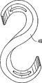
Figure 19 is the side view that is used for the S-shape shank shin of described false foot, and its thickness is diminishing to two ends from the centre part.
Figure 20 is the another kind of example of S shape shank shin, and its thickness only dwindles in the top.
Figure 21 is the side view that is used for the J-shaped shank shin of the false foot of the present invention, and it all attenuates at each end.
Figure 22 is the sketch map that is similar to Figure 21, and but, what its was represented is that its thickness is only at the diminishing J-shaped shank of the direction shin towards its upper end.
Figure 23 be of the present invention adjust use in the fastening structure be used for the shank shin is connected the aluminum on the foot Os Draconis shown in Figure 3 or the side view that leans on slightly of plastics link.
Figure 24 is used in shown in Fig. 3-5 on the false foot, is used for foot is connected on the pylon so that be connected the side of the pylon adapter on amputee's the lower limb and the positive sketch map of deflection slightly.
Figure 25 is the side view that is similar to the false foot of another kind of the present invention of Fig. 3, but but expression be to use link with two release fasteners, described securing member longitudinal separation ground is connected to described parts on shank shin and the foot Os Draconis.
Figure 26 is the enlarged side view of link shown in Figure 25.
Figure 27 is the enlarged side view of the shank shin of false foot shown in Figure 25.
The specific embodiment
Referring to accompanying drawing, false foot 1 in embodiment shown in Fig. 3-5 comprises the foot Os Draconis 2 of longitudinal extension, have a foot leading portion part 3 at the one end, have foot back segment part 4, and extend the foot stage casing part 5 that upwards arches upward between foot leading portion part and the foot back segment part at its opposite end.In an embodiment, foot stage casing part 5 is bending protruding upward on the whole longitudinal extent between foot leading portion part and the foot back segment part.
By releasable securing member 8 and link 11, the axial shank shin 6 of foot 1 part in its curved lower end of protruding downwards 7 is connected on the approaching posterior face of described Os Draconis foot stage casing part 5.In the present embodiment, securing member 8 is the bolt with nuts and washers just, but, also can be releasable clip or other securing members, is used for when fastening this securing member the shank shin located reliably and remain on the foot Os Draconis.
Referring to Fig. 8, on the approaching rear surface of the foot stage casing of Os Draconis part 5, formed the hole 9 of a longitudinal extension.For example, as shown in figure 15, on the lower end 7 of the bending of shank shin 6, formed the hole 10 of a longitudinal extension equally.Releasable securing member 8 extends through hole 9 and 10, they can adjust shank shin and the alignment relative to each other of foot Os Draconis on the longitudinal direction of A-A shown in Figure 5, at this moment, securing member 8 be unclamp or discharge adapt to specific task so that the performance of described false foot adjusted to.Therefore, the hole 9 and 10 of securing member 8, link 11 and longitudinal extension has constituted a kind of adjustable fastening structure, is used for the shank shin is connected the foot Os Draconis, so that form the ankle joint position of false foot.
Adjust the effect of the alignment of shank shin 6 and foot Os Draconis 2 from Fig. 1 and 2 as can be seen, wherein, two radius Rs 1 one by one and R2 represent the curved surface adjacent, in opposite directions, that arch upward or that protrude of foot Os Draconis mid portion 5 and shank shin 6.When such two radiuses be considered to one by another the time, in Fig. 1, have motor capacity perpendicular to tangent line A, in Fig. 2, have motor capacity perpendicular to tangent line A1, described tangent line draws between above two radiuses.Mutual relation between these two radiuses has determined the direction of motion output.As a result, the dynamic response force of foot 1 is used this relation that depends on.The radius of depression is big more, and dynamic response capability is high more.But, radius is more little, and its reaction is fast more.
The shank shin on the false foot of the present invention and the alignment capabilities of foot Os Draconis make described radius to shift, so that influence level or the vertical linearity speed of described foot in motor activity.For example, in order to improve the horizontal linearity speed ability of false foot 1, the change that can align is so that influence the relation of shank shin radius and foot Os Draconis radius.In other words, in order to improve the horizontal linearity velocity characteristic, compared to Figure 1, make that in Fig. 2 the bottom radius R2 of foot Os Draconis is more farther than its original position.Changed the dynamic response feature thus, and made the motion output of foot 1 more trend towards horizontal direction, consequently, can obtain bigger horizontal linearity speed by applying identical power.
The amputee can find each the active setting value that satisfies his/her needs by taking exercise because these need with the horizontal and vertical lines velocity correlation.For example, the high jumper needs higher vertical commencing height with the basket baller than the sprinter.Link 11 is alignment links (referring to Fig. 3,4 and 23) of plastics or metallic aluminium, is clipped between the foot Os Draconis 2 and shank shin 6 of connection.Releasable secure component 8 extends through the hole 12 in the link.Described link extends along the coupling part approaching, the rear surface of shank shin and described Os Draconis foot stage casing part 5.
The lower end 7 of the bending of shank shin 6 is parabolic shapes, and this parabolical minimum profile curvature radius is positioned at its lower end, and at first on described parabolic shape forward, then extend upward.As shown in Figure 3, by the shank shin be bent to form one towards after depression.The advantage of described parabolic shape is, it has higher dynamic response feature, and it can produce the horizontal linearity speed of the improvement relevant with bigger radius near-end, has less radius of curvature in its lower end simultaneously, so that have response feature faster.Explain that as Fig. 1 and 2 described parabolic shape bigger radius of curvature in the top makes tangent line A along with the change of alignment keeps vertically more, this can produce the horizontal linearity speed of having improved.
In the present embodiment, the foot leading portion of foot Os Draconis 2, foot stage casing and foot back segment partly are made of a slice elastomeric material.For example, can adopt the solid material of plastic nature, it during deflection, has the feature that keeps shape under the effect of ground reaction force.Specifically, can will be that the extruding plastic that uses of trade mark or the polyurethane copolymer of the degassing are used to produce the foot Os Draconis and produce the shank shin with the stacked high strength graphite of thermosetting epoxy resin or with Delran.The service quality relevant with described material provides high strength and lightweight and minimized creep.Described thermosetting epoxy resin is to adopt the artificial limb industry standard laminated under vacuum condition.Polyurethane copolymer can be injected die, and can carry out machined the plastic of extruding.Employed each material all has its merits and demerits.
The physical features that described elastomeric material is relevant with hardness, elasticity and intensity all is by the decision of the thickness of this material.For the material of equal densities, the thin thicker easier deflection of material of material.Employed material, and physical features is relevant with the hardness of the flexible characteristic of false foot Os Draconis and shank shin.In the embodiment of Fig. 3-5, the thickness of foot Os Draconis and shank shin is uniform or symmetric, but, as mentioned below, thickness along described part length direction can change, as by making foot back segment position and foot leading portion position become thinner, and more responsive to the deflection at position, foot stage casing.
Has arc longitudinally for the false foot 1 with height dynamic response capability being provided, foot stage casing part 5 being made, so that this vertical arcual inside part has higher dynamic response capability than described vertical arcual Outboard Sections.For this reason, in described embodiment, the radius in its outside of the radius ratio of the inside part of described vertical arc-shaped recess is big.The rear end 17 of foot back segment part 4 is arcuate shape of being bent upwards, and it can be reacted to the counteracting force on ground during heel is subjected to absorbing the bump that ballistic compression stress causes.The heel that is formed by foot back segment part 4 has a rear outside turning 18, and it more leans on the back with more in the outer part than inside corner 19, so that promote the foot back segment to turn up in the initial contact phase of gait.The shape of the front end 20 of foot leading portion part 3 is the arcs that are bent upwards, so that anthropomorphic dummy's toe lifts the dorsiflex state of the position that toe leaves at the heel of the back stance phase of gait.Below foot leading portion and foot back segment, provide rubber or foam pad 53 and 54 as padded coaming.
Produced the biplanar motion capability of the improvement of described false foot by inboard that extends through the foot leading portion part 3 between its back side and the plantar surfaces of toe and expansion joints hole, the outside 21 and 22. Expansion joints 23 and 24 extends to the forward edge of described foot leading portion part forward from a corresponding hole, so that form inboard, the middle part and the expansion strut 25-27 outside, these pillars produced the foot Os Draconis foot leading portion part improvement biplanar motion capability. Expansion joints hole 21 and 22 is that the line B-B in Fig. 5 is localized in transverse plane, it is that longitudinal axis A-A with the foot Os Draconis is 25 °-35 ° α angle and extends, inboard expansion joints hole 21 is more forward than expansion joints hole 22, the outside, the expansion joints hole 21 and 22 that projects on the sagittal plane is to tilt with the relative described transverse plane in 45 ° angle, makes the back side in described hole more forward than plantar surfaces of toe.By this structure, distance from releasable secure component 8 to expansion joints hole, the outside 22 is shorter than the distance from releasable secure component to inboard expansion joints hole 21, the Outboard Sections of so false foot 1 has short toe lever than inside part, so that make foot stage casing part have the height dynamic response capability.
The front portion of the foot back segment part 4 of foot Os Draconis 2 also comprises an expansion joints hole 28 of extending by the foot back segment part between its back side and the plantar surfaces of toe 4.Expansion joints 29 28 extends rearward to the back edge of foot back segment part from the hole, so that form expansion strut 30 and 31.Produced thus described false foot foot back segment part improvement biplanar motion capability.
As shown in Figure 3, the foot stage casing part 5 of foot Os Draconis 2 and the back side of foot leading portion part 3 have formed the depression 32 that makes progress, and it has just simulated the function of the 5th axis of movement (ray axis ofmotion) of people's foot like this.In other words, depression 32 has a longitudinal axis C-C, longitudinal axis A-the A of it and foot Os Draconis is the β angle of 20-35 degree, its inside part is more forward than the outside, so that the 5th axial-movement in the promotion gait, as the axis that slowly runs (low gear axis of rotation) of the inclination of second to the 5th sole of the foot portion of people's foot.
When the amputee steps in the inboard of foot or during the outside, just is appreciated that the importance of biplanar motion capability in uneven local walking or as the athlete.The direction of ground force vector changes over the plane, component that has forward from the direction of sagittal.Ground can be along the direction inside thruster described foot opposite with the described foot of outside thruster.Consequently, the shank shin tilts to the inside, and its weight is applied on the inside structure of described foot Os Draconis.At this pressure, dorsiflex (upward deflecting) and upset take place in the inboard expansion joints pillar 25 of foot Os Draconis 2 and 31, and outside expansion joints pillar 27 and 30 is to plantar flexed (deflecting down) and upset.This motion is attempted the plantar surfaces of toe of foot plate is placed on (plantar surfaces of toe grade) on the ground.
Referring to Fig. 6 and 7, another kind of foot Os Draconis 33 of the present invention can be used on the false foot of the present invention especially for the foot Os Draconis of hurrying up.To become can only be sagittal plane orientation to the center of gravity of human body when hurrying up.Described false foot needn't have low dynamic response feature.As a result, do not need the foot leading portion of foot Os Draconis 2, the longitudinal axis of foot stage casing female to have the outside direction of rotation of 35 degree.On the contrary, the longitudinal axis D-D direction of described depression can become and be parallel to horizontal frontal plane, shown in Fig. 6 and 7.This makes the foot of hurrying up to react along the direction of sagittal.In addition, expansion joints hole 34 and 35 directions at foot leading portion and foot stage casing part E-E along the line are parallel to horizontal frontal plane, and promptly apertura lateralis 35 is proal, and with inboard aperture 34 being aligneds and be parallel to described horizontal frontal plane.The front end 36 of foot Os Draconis 33 also is parallel to described horizontal frontal plane.The rear end heel part 37 of described foot Os Draconis also is parallel to described horizontal frontal plane.This change has produced negative effect to the multipurpose ability of described false foot.But, its performance characteristic becomes and more can be fit to special duty.The another kind of dash foot Os Draconis 33 changes in the toe axis district of the foot leading portion part of described foot, and wherein, the dorsiflex of the degree of 15 on the foot Os Draconis 2 is increased to the dorsiflex of the 25-40 degree of foot Os Draconis 33.
Fig. 9 and 10 expressions are used for the of the present invention another kind of foot Os Draconis 38 of false foot, and this false foot is specially adapted to amputee through the Symes amputation of the foot use of hurrying up.For this reason, the foot center section part branch of foot Os Draconis 38 comprises the depression that makes progress 39 at a rear portion, and wherein, the lower end of the bending of described shank shin is connected with described foot Os Draconis by releasable securing member.This foot Os Draconis can be used by all lower extremity amputees.Foot Os Draconis 38 are adapted on the long residual limbs that Symes level amputee is correlated with.Its performance characteristic is, and is obviously faster aspect dynamic response capability.Its use is not to be that other amputation of this level is peculiar.It can be used in all tibias and the femur amputation.Foot Os Draconis 40 among Figure 11 and 12 the embodiment also have the depression 41 that is used for the Symes amputee, and described foot Os Draconis make described false foot have height dynamic response feature, and biplanar motion capability, are similar to the embodiment in Fig. 3-5 and 8.
The functional character of some kinds of foot Os Draconis of false foot 1 is relevant with its shape and design feature, because they are relevant with the physical features of depression, outstanding, radius size, expansion, compression and material, all these features are with relevant to the retroaction of ground force when walking, race and the jump activity.
Foot Os Draconis 42 among Figure 13 are similar to the embodiment in Fig. 3-5 and 8, and different is that the rear portion that the thickness of foot Os Draconis is assigned to the foot back segment from the foot center section part diminishes.The thickness of the foot Os Draconis 43 among Figure 14 reduces gradually in its front-end and back-end or dwindles.In shank shin 44 in Figure 14 and the shank shin 45 among Figure 16 similar varied in thickness has been shown, described shank shin can be used on the false foot 1.Each design of foot Os Draconis and shank shin has produced different function results, because these functions result and horizontal and vertical lines velocity correlation, they are that the performance of improving in the task relevant with various motions is peculiar.The adjustment of the setting between capability of multiple calf shank configurations and foot Os Draconis and the shank shin, produced a kind of false foot shank shin relation, it makes amputee and/or prosthetist have and regulates false foot so that obtain the ability of specific one optimum performance in multiple motion and recreation.
Other shank shins that are used for false foot 1 have been shown in Figure 17-22, and have comprised C shape shank shin 46 and 47, S shape shank shin 48 and 49 and J-shaped shank shin 50 and 51.The upper end of shank shin can also have vertical end, has connected a taper connection plate at this near-end.A male cone (strobilus masculinus) body bolt can be connected the vertical end of shank shin and pass this vertical end.Can also in the elongated hole of the near-end of shank shin and far-end, provide plastics or Al filler, so that receive described near-end male cone (strobilus masculinus) body and distal foot Os Draconis.False foot of the present invention is a kind of modular system, is preferably made by Standardisation Cell or size, so that have motility and multiple use.
The activity of running that all are relevant with runway is all carried out in the counterclockwise direction.Another kind of selectional feature of the present invention has been considered the power that acts on the foot that moves along this crooked route.When object when crooked route moves, entad acceleration is towards center of rotation.Newton's third law is applicable to this energy.This is a kind of equating and opposite effect.Therefore, for each " entad " power, there is " centrifugal " power.The effect of centripetal force is towards center of rotation, and its counteracting force, action of centrifugal force is away from center of rotation.If the curve of athlete on runway run, centripetal force pulls to described center of curve with the athlete, and centrifugal force pulls to it away from described center of curve simultaneously.Tend to the centrifugal force that makes the runner outward-dipping in order to offset, runner's health slopes inwardly.If the rotation direction of runner on runway is anticlockwise words always, its left side is exactly the inboard of runway.Consequently, according to feature of the present invention, can the ratio right side that do in the left side of the false foot shank of left and right side shin is thinner, and can improve the athletic bend performance of amputation.
In some kinds of embodiments, foot Os Draconis 2,33,38,42,43 all is 29 centimeter length, at Fig. 3,4 and 5, and proportional with footwear 1 in the sketch map of some different shank shins and foot Os Draconis.But, the technical staff is understandable that the specific dimensions of false foot can change according to the amputee's that this foot is housed the bodily form, body weight and other features.
To discuss below in the walking of gait cycle and the operation of the false foot 1 of stance phase of running.With three law of motions of the newton that the law of inertia, acceleration and active force-the counteracting force law is relevant, be the basis of motion-promotion force of foot 2.According to Newton's third law, i.e. active force-counteracting force law, as can be known the ground thrust that pushes away described foot and the foot thrust that pushes away ground equate and direction opposite.This power is called as ground reaction force.To people walking, run and multiple scientific research has been carried out in the jump activity.Force plate research is told us, has occurred Newton's third law in gait.By above-mentioned research, we have understood the direction that ground pushes away foot.
The active stance phase of walking/run can further be divided into and slow down and accelerated period.When false foot touched ground, foot pushed away ground forward, and ground equally along opposite direction toward pushing back foot, ground is to the false foot of pusher in other words.This power makes described false foot move.The walking and the active stance phase analysis of running start from the contact point at the rear outside turning 18 among Fig. 3 and Figure 18, this turning than the more inclined to one side back of the inside part of foot and the outside some.This skew when beginning to contact causes the foot upset, and makes shank shin generation plantar flexed.The shank shin is being sought a kind of position always, so that shift body weight by its shin, for example, it tends to make its long vertical member to be in the position opposite with ground force.This mobile backward just plantar flexed is so that the reason opposite with ground reaction force, and described ground reaction force is to the described foot of pusher.Described ground force causes the compression of shank shin, and its near-end is moved backward.The compression of the compact radius of shank shin bottom, the bending of anthropomorphic dummy's ankle joint plantar, and by compression the foot leading portion is reduced on the ground.Meanwhile, upwards press by compression the back on the top of foot Os Draconis 2.These two kinds of compression stresses all play a part shock absorber.In case the shank shin stops to move to the plantar flexed state, and by ground to the pusher foot, further strengthened this impact absorption by the rear outside heel 18 of biasing, it can cause foot upset, it plays a part shock absorber equally.
The compression member of foot Os Draconis and shank shin begins unloading subsequently, seeks its original-shape in other words, and discharges energy stored---and this can cause the near-end of shank shin to travel forward in the mode of quickening.When shank shin during near its vertical initial state, ground force pushes away foot vertically upward from changing over to the pusher foot.Because false foot has rear portion and anterior plantar surfaces of toe weight bearing district, and these districts are that arc mid portion by nonweight-bearing length connects, and can cause by expansion long arc mid portion being loaded from the power of the vertical direction of artificial limb.Rear portion and anterior load-bearing surface separate.The arc mid portion of the length that there is described foot in the trying hard to keep of described vertical direction, this moment ground force from vertical direction transfer to forwards to.The shank shin expands, similar ankle dorsal flexion.This can cause false foot rotation to depart from the load-bearing surface, vola of front.The arc of the length in foot stage casing changes over expansion from being compressed.Like this vertical compression force energy that stores is released into the swelliong power of having improved.
The arc of the length of foot Os Draconis and shank shin can be resisted the expansion of its corresponding construction.As a result, limited the shank shin and pushed ahead, and foot begins to rotate the weight bearing area that departs from anterior plantar surfaces of toe.The expansion of the foot stage casing part of described foot Os Draconis has and Fig. 3-5 and 8, Figure 11 and 12, the height responding ability that the foot Os Draconis of Figure 13 and 14 illustrated embodiment are the same.Because the foot stage casing foot leading portion transition portion of described foot Os Draconis, the long axis of foot outwards departs from 25 °-35 ° relatively, and the inboard long arc arc longer than the outside is longer.This point is important because on normal foot, quickening or between deceleration phase, use be the inside part of foot.
The long inboard arc of described false foot has higher dynamic response feature than the outside.When walking or running, used the short toe lever in the outside with slower speed.Body's center of gravity is by sinusoidal space motion.It moves inboard, the outside, near-end and far-end.When walking or running with slower speed, the degree ratio that body's center of gravity moves more trends towards the inboard and the outside when walking or running fast.In addition, momentum or inertia are lower, and it is lower to overcome the ability of higher dynamic response capability.False foot of the present invention is fit to adopt described principle in the mode of application machine.
When the power on ground pushed away false foot forward, this vacation foot was to pusher ground, and when heel began to lift, the arcual forward profile of the length of foot stage casing part vertically was applied to the power of these backward directions on its plantar surfaces of toe.This is the most effective and the most useful mode that applies this power.Kindred circumstances can appear in the rear portion of the foot back segment part of false foot.Its shape makes also that when beginning to contact ground force backward is opposite with plantar surfaces of toe perpendicular to the foot Os Draconis of the direction that applies power.
In the late period that heel lifts, toe leaves the walking and the motion of running, the axis district dorsiflex 15-35 degree of foot leading portion part.This position of the feasible ground force compressing foot forward of this upwardly extending radian.To the resistance of this compression stress less than to the expansion of the shaking peroid that occurs in false step attitude and run and the resistance that seamlessly transits.In later stages of stance phase, segment length's arc discharges the energy of its preservation in expansible shank shin and the expansible foot, strengthens the thrust to amputee's centre of body weight.
In several embodiments of mentioning in front, the rear portion of the foot back segment of foot Os Draconis and foot leading portion part combines expansion joints hole and expansion joints pillar.The direction in described expansion joints hole plays a part the mitered hinge, and has improved biplanar motion capability, so that improve the overall contact characteristic of the plantar surfaces of toe of foot when the walking of uneven place.
The dynamic response capability of the Symes foot Os Draconis shown in Fig. 9-12 is obviously different because this ability and walking, run relevant with the jump activity.Described foot Os Draconis are in 4 different aspects difference to some extent.There is a depression comprising the rear portion of closing on, so that can adapt to the Symes distal residual limb shape better than the plane in foot stage casing part.The corresponding front and rear radius that described alignment depression needs arc-shaped feet Os Draconis mid portion is more deep and size is littler.As a result, all foot stage casing long arc radiuses and foot back segment radius are compacter and littler.This has obviously influenced the dynamic response feature.Less radius has produced lower dynamic response potentiality.But, described false foot to above-mentioned all walkings, run and jumping ground forces is made faster reaction.The result obtains having the foot faster of low dynamic response.
Use false foot of the present invention, change the task specificity exercise performance that to be improved by alignment, because described alignment changes the vertical and horizontal component that can influence every motion.Described people's foot is multi-functional unit, and it can be walked, runs and jump.On the other hand, people's tibia fibula shank shin structure is not multi-functional unit.It is a kind of simple lever, it walking, run and the jump activity in be parallel to it vertical near-end-distal direction apply its power.It is a kind of incompressible structure, and does not have the potentiality of preserving energy.On the other hand, false foot of the present invention has dynamic response capability, because this dynamic response capability is walked with motion, the active horizontal and vertical lines velocity component of running and jump is relevant, and is better than human tibia and fibula.As a result, there is the probability of improving amputee's athletic performance.For this reason,, unclamped securing member 8, and adjusted shank shin and the alignment relative to each other of foot Os Draconis along the longitudinal direction of foot Os Draconis according to the present invention.This variation as illustrated in fig. 1 and 2.With securing member 8 the shank shin is fixed on the adjustment position of foot Os Draconis then.At this conditioning period, the bolt of secure component 8 is one or two slip in relative, the hole 9 and 10 that is long, longitudinal extension on relative foot Os Draconis and the shank shin respectively.
Can improve a kind of so in this way change of alignment Change Example of the runner makes him when hurrying up the foot plane performance characteristic when beginning kiss the earth, wherein, the relative shank shin of foot Os Draconis is to front slide, and the vola is crooked on described shank shin.This new relation has been improved the horizontal component of running.In other words, shank shin vola is to the foot bending, and foot contacts with ground with the foot flat condition, and opposite with the heel contact of beginning, the ground horse back is to the pusher foot, and foot is to push away ground forward.Cause shank shin (by expand) and move downward fast forward thus.Produce dynamic response force by expanding, this mechanical resistance hinders the direction of shank shin initial movement.As a result, foot rotates above sole of the foot portion plantar surface weight bearing area.This causes the foot stage casing demi-inflation of described foot Os Draconis, and it is bigger than the resistance of compression.The shank shin expands and part expansible clean effect in foot stage casing is that further pushing ahead of shank shin stoped, this can make the knee expansion apparatus of user's body and buttocks expansion apparatus in more effective mode forward with to the near-end center of gravity (speed of promptly improving the standard) of moving.In this case, more more make progress forward under the situation than heel toe runner, this heel toe runner's shank shin pushes ahead when being subjected to beginning that to have a resistance of shank shin of bigger dorsiflex (vertically) than the flat runner of foot littler.
In order to study the function of dash foot, to the alignment change of shank shin and foot Os Draconis.The advantage of described foot Os Draconis is that the longitudinal axis orientation of its all depressions all is parallel to horizontal frontal plane.The shank shin is a plantar flexed, and slides backward on the foot Os Draconis.Compare with flat foot runner, this has further reduced the far-end circular arc, for example, has the multipurpose foot Os Draconis that are similar to shown in Fig. 3-5 and 8.As a result, have bigger horizontal movement potential energy and dynamic response aspect its improved horizontal capability.
The dash man has bigger motion, power and momentum (inertia) scope, and momentum is a motive power.Because be shorter than the acceleration time deceleration time of its stance phase, obtained higher horizontal linearity speed.This means that when beginning to contact when the toe kiss the earth, ground is to the pusher foot, and foot pushes away ground forward.Flat running player comes comparison with the initial foot that contacts, and has more energetically shank shin with momentum and is forced to produce bigger crooked and move downward.The result of described power is to load by the arc-shaped recess of expansion to the length of foot, and by expanding the shank shin is loaded.The degree that described expansive force is resisted greater than mentioned before every other with the relevant power of running.As a result, the dynamic response capability of described foot is directly proportional with applied force.The reaction of people's tibia fibula shank shin is only relevant with energy force potential energy, and it is a kind of straight structure, and can not storage power.When dash, the expansive force on the false foot of the present invention greater than mentioned before every other with the walking and the relevant power of running.As a result, compare with the human body function, the dynamic response capability of described foot is directly proportional with applied force, and can strengthen amputation sporter's exercise performance.
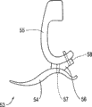
In shank shin 55 upper ends a slotted hole 59 is set, is used to hold pylon 15.In case after including in the described hole, just can by tight a bolt 60 and 61 with the pylon fixation clamp on the shank shin, the lateral margin freely 62 and 63 along described hole with the shank shin is pulled in together.Can adjust this pylon connection easily by unclamping described bolt, the relative shank shin of pylon is flexible to the position that needs, and, again described pylon is clamped to described adjustment state by the described bolt of tensioning.
Explanation to embodiment leaves it at that.Although the present invention is illustrated in conjunction with multiple declaration embodiment, should be understood that those skilled in the art can visualize multiple other improvement and embodiment, these improve and embodiment belongs to the design and the scope of the principle of the invention.More particularly, under the premise of the concept of the present invention, in the scope of above-mentioned explanation, accompanying drawing and appended claims is feasible to the building block of combinative structure of the present invention and/or the rational changes and improvements of layout.Except the changes and improvements to building block and/or layout, other purposes also are conspicuous for a person skilled in the art.
Claims (72)
1. false foot comprises:
The foot Os Draconis of a longitudinal extension;
An elastic integrally formed shank shin, this shank shin is connected in the lower end of shin on the foot Os Draconis so that vertically this shin and foot Os Draconis are located relative to each other securely along the foot Os Draconis, this shin extends upward from the foot Os Draconis in the mode of curve basically, so that ankle joint position that forms false foot and the following artificial limb part that is used for the approximate vertical orientation of lower limb more than the ankle joint position that supporting structure on people's lower limb deformed limb is connected;
Wherein, from at least a portion of upwardly extending this shin of foot Os Draconis is towards preceding outstanding bending, and wherein, the artificial limb part of the lower limb of ankle joint position and shin response ground reaction force thereon during gait is compressible and expandable, improves the dynamic response of the false foot in the gait so that store and release energy.
2. false foot as claimed in claim 1, it also comprises and is used to adjust described shank shin and described foot Os Draconis relative to each other along the device of alignment longitudinally of described foot Os Draconis, thereby adjust the performance of described false foot for particular task, wherein, the described device that is used for adjusting alignment comprises the hole of the longitudinal extension at least one of described foot Os Draconis and described shank shin, and a releasable securing member extends through described hole, thereby adjustably described shank shin is connected on the described foot Os Draconis so that adjust described alignment.
3. false foot as claimed in claim 2, wherein, each in described foot Os Draconis and the described shank shin is provided with the hole of longitudinal extension, and described releasable securing member extends through this hole.
4. false foot as claimed in claim 1, it also comprises the link between described shank shin and described foot Os Draconis, and releasable securing member extends through the hole in the described link so that by this link described shank shin is connected on the described foot Os Draconis.
5. false foot as claimed in claim 4, wherein, described releasable securing member is connected to described link on the described foot Os Draconis, and wherein, be provided with another releasable securing member, this another releasable securing member is connected to described link on the described shank shin, so that described shank shin is connected on the described foot Os Draconis.
6. false foot as claimed in claim 5, wherein, on the described direction longitudinally of described foot Os Draconis, described releasable securing member and described another releasable securing member are spaced apart from each other in described link.
7. false foot as claimed in claim 6, wherein, after described another releasable securing member more leans on than described releasable securing member.
8. false foot as claimed in claim 1, wherein, described is parabolic shape towards preceding outstanding sweep, described parabolical minimum profile curvature radius is positioned at the lower end of shank shin, and extends upward in described parabolic shape.
9. false foot as claimed in claim 1, wherein, described shank shin is a S shape, the described towards preceding outstanding sweep of described shank shin formed at the bottom of described S shape.
10. false foot as claimed in claim 1, wherein, described shank shin is a J-shaped, the described towards preceding outstanding sweep of described shank shin formed at the bottom of described J-shaped.
11. false foot as claimed in claim 1, wherein, it is corresponding free end that in the end of two perpendicular separations of described shank shin each is highlighted rounding, this free end extends on identical direction along the foot Os Draconis of described longitudinal extension, and the straight relatively upstanding portion of described shank shin that connects the end of described rounding is positioned on the side opposite with a described free-ended side of this shank shin.
12. false foot as claimed in claim 1, wherein, the shank shin that forms the following artificial limb part of lower limb extends upward in the mode of curve basically, and this curve back-flexing merges with the straight vertical upper with the shank shin.
13. false foot as claimed in claim 1, wherein, described foot Os Draconis at one end have a foot leading portion part, has foot back segment part at opposite end, and the foot stage casing part that upwards arches upward between described foot leading portion part and foot back segment part, and wherein, each in described foot leading portion part and the described foot back segment part is crooked to being recessed on.
14. false foot as claimed in claim 1, wherein, described foot Os Draconis at one end have a foot leading portion part, has foot back segment part at opposite end, and the foot stage casing part that upwards arches upward between described foot leading portion part and foot back segment part, and wherein, the described foot stage casing part of described foot Os Draconis projects upwards crooked on the whole longitudinal extent between described foot leading portion part and the described foot back segment part.
15. false foot as claimed in claim 1, wherein, described foot Os Draconis at one end have a foot leading portion part, has foot back segment part at opposite end, and the foot stage casing part that upwards arches upward between described foot leading portion part and foot back segment part, and wherein, the described foot center section part branch of described foot Os Draconis comprise a rear portion, towards last depression, in this depression, the described curved lower end of described shank shin is connected on the described foot Os Draconis.
16. false foot as claimed in claim 1, wherein, described foot Os Draconis at one end have a foot leading portion part, has foot back segment part at opposite end, and the foot stage casing part that upwards arches upward between described foot leading portion part and foot back segment part, and wherein, described foot back segment partly comprises a heel that has the rear outside turning, this rear outside turning more leans on the back with in the outer part than the inside corner of heel, so that promote the partial switching of foot back segment during the initial contact phase of gait.
17. false foot as claimed in claim 1, wherein, described foot Os Draconis at one end have a foot leading portion part, has foot back segment part at opposite end, and the foot stage casing part that upwards arches upward between described foot leading portion part and foot back segment part, and wherein, the plantar surfaces of toe of the foot stage casing part of described foot Os Draconis has arcuate depression longitudinally, and the radius of its inside part is greater than the radius of its Outboard Sections.
18. false foot as claimed in claim 1, wherein, described foot Os Draconis at one end have a foot leading portion part, has foot back segment part at opposite end, and the foot stage casing part that upwards arches upward between described foot leading portion part and foot back segment part, and wherein, the posterior components of the described foot stage casing part of described foot Os Draconis and described foot leading portion part is formed with towards last depression, the function of the 5th axis of movement of this depression anthropomorphic dummy foot, the longitudinal axis of described depression is oriented and becomes 20 °-35 ° angle with the longitudinal axis of foot Os Draconis, inboard more forward so that promote the 5th axial-movement in the gait than the outside, as the axis that slowly runs of the inclination of second to the 5th sole of the foot portion in people's foot.
19. false foot as claimed in claim 1, wherein, described foot Os Draconis at one end have a foot leading portion part, has foot back segment part at opposite end, and the foot stage casing part that upwards arches upward between described foot leading portion part and foot back segment part, and wherein, the rear portion of the foot leading portion of described Os Draconis part comprises the inboard that extends through the described foot leading portion part between its dorsal part and the plantar surface and the expansion joints hole in the outside, expansion joints is from the more corresponding leading edge that extends to foot leading portion part forward in described hole, so that form inboard, the expansion strut in the centre and the outside, these pillars have produced the biplanar motion capability of the foot leading portion improvement partly of described foot Os Draconis.
20. false foot as claimed in claim 19, wherein, along a line location, this line becomes 25 °-35 ° angle to extend with the longitudinal axis of foot Os Draconis in transverse plane in described expansion joints hole, and the expansion joints hole in the inboard expansion joints boring ratio outside is more forward.
21. false foot as claimed in claim 19 wherein, is projected in described expansion joints hole and transverse plane angle inclination at 45 on the sagittal plane, the posterior components in these holes is more forward than vola part.
22. false foot as claimed in claim 19, wherein, distance from releasable securing member to expansion joints hole, the outside is shorter than the distance from releasable securing member to inboard expansion joints hole, make the Outboard Sections of false foot have shorter toe lever, so that can access the high and low dynamic response of foot stage casing part than inside part.
23. false foot as claimed in claim 1, wherein, the front end of described foot Os Draconis is configured as the arc that is bent upwards, so that the people's of dorsiflex toe takes place on the position that the heel lift toe in late period of standing of gait leaves in simulation.
24. false foot as claimed in claim 1, wherein, described foot Os Draconis at one end have a foot leading portion part, has foot back segment part at opposite end, and the foot stage casing part that upwards arches upward between described foot leading portion part and foot back segment part, and wherein, the rear portion of the foot leading portion part of described Os Draconis comprises at least one the expansion joints hole that extends through the described foot leading portion part between its dorsal part and the plantar surface, expansion joints extends to the leading edge of foot leading portion part forward from described expansion joints hole, so that form a plurality of expansion strut, these pillars have produced the biplanar motion capability of the foot leading portion improvement partly of described foot.
25. false foot as claimed in claim 1, wherein, described foot Os Draconis at one end have a foot leading portion part, has foot back segment part at opposite end, and the foot stage casing part that upwards arches upward between described foot leading portion part and foot back segment part, and wherein, the described foot leading portion of described Os Draconis, foot stage casing and foot back segment part are formed by single piece of resilient material.
26. false foot as claimed in claim 25, wherein, described elastomeric material is semirigid plastics.
27. false foot as claimed in claim 1, wherein, described foot Os Draconis are formed by the semi-rigid material that has vertical arcuate section, this arcuate section is configured as and produces the dynamic response capability of described foot in gait, make the inside part of vertical arcuate section have higher relatively dynamic response capability, and the Outboard Sections of described vertical arcuate section have relatively low dynamic response capability.
28. false foot as claimed in claim 1, wherein, the rear end of described foot Os Draconis is configured as the arc that is bent upwards, and it is had an effect with ground reaction force in the ballistic process of the heel that compression causes, so that absorbing vibration.
29. false foot as claimed in claim 1, wherein, described foot Os Draconis at one end have a foot leading portion part, has foot back segment part at opposite end, and the foot stage casing part that upwards arches upward between described foot leading portion part and foot back segment part, and wherein, the front portion of the foot back segment part of described Os Draconis comprises the expansion joints hole that extends through the described foot back segment part between its dorsal part and the plantar surface, expansion joints extends rearward to the back edge of foot back segment part from described expansion joints hole, so that form a plurality of expansion strut, these pillars have produced the biplanar motion capability of the foot back segment improvement partly of described foot.
30. a false foot comprises:
The foot Os Draconis of a longitudinal extension, these foot Os Draconis at one end have a foot leading portion part, have foot back segment part at opposite end, and the relatively long foot stage casing part of extending and upwards arching upward between described foot leading portion part and foot back segment part;
One comprises the shank shin towards preceding outstanding curved lower end; And
An adjustable fastening structure, this fastening structure is connected to the described curved lower end of described shank shin on the described foot stage casing part of described Os Draconis, so that form the ankle joint position of described false foot; And
Wherein, described adjustable fastening structure can be adjusted described shank shin and described foot Os Draconis relative to each other along the alignment longitudinally of described foot Os Draconis, thereby adjusts the performance of described false foot.
31. false foot as claimed in claim 30, wherein, described adjustable fastening structure comprises at least one releasable securing member and the link between described shank shin and described Os Draconis, and described link and described at least one adjustable securing member are connected to described shank shin on the described foot Os Draconis.
32. false foot as claimed in claim 31, wherein, described adjustable fastening structure comprises the hole of the longitudinal extension in each of described shank shin and described foot Os Draconis, corresponding releasable securing member is being admitted in these holes, and make described shank shin and described Os Draconis on certain adjusting range, vertically to slide relative to each other, thereby adjust the performance of described false foot along described.
33. false foot as claimed in claim 30, wherein, extend to the front upper place from described lower end the lower end of the described outstanding bending of described shank shin.
34. false foot as claimed in claim 1, the adapter that it also comprises the upper end that is connected to the shank shin is used for false foot is connected to supporting structure on people's lower limb deformed limb.
35. false foot as claimed in claim 1, wherein, the foot Os Draconis have an anterior plantar surfaces of toe weight bearing area, and this weight bearing area comprises the expansion strut that the lateral spacing of the biplanar motion capability that has produced the foot Os Draconis is opened.
36. false foot as claimed in claim 1, wherein, the shank shin is formed by single piece of resilient material.
37. false foot as claimed in claim 1, wherein, the foot Os Draconis have rear portion and anterior plantar surfaces of toe weight bearing area, and extend between these weight bearing areas at nonweight-bearing middle part.
38. false foot as claimed in claim 37, wherein, this front portion plantar surfaces of toe weight bearing area be oriented with the longitudinal axis of foot Os Draconis at angle, it is inboard than more forward outside it.
39. false foot as claimed in claim 1, wherein, this shin extends upward in the mode of curve basically above the ankle joint position.
40. false foot as claimed in claim 1, wherein, this shin has straight vertical upper.
41. false foot as claimed in claim 1, wherein, these foot Os Draconis comprise foot leading portion part, foot stage casing part and foot back segment part.
42. false foot as claimed in claim 1, wherein, anthropomorphic dummy's ankle joint plantar bending of ankle joint position and dorsiflex.
43. a shank shin that is used for false foot, it comprises:
Elongated, semirigid elastomeric element, end at described parts has towards preceding outstanding sweep so that be connected with the foot Os Draconis, thereby form the ankle position towards preceding outstanding bending of false foot, the opposite end of described parts has the device that is used for described shank shin is connected to the supporting structure on amputee's the lower limb, and wherein, the described of a described end place of described parts is provided with an adjustable fastening structure towards preceding outstanding sweep, be used for during using false foot, parts being connected to the foot Os Draconis, this adjustable fastening structure makes that false foot user can be along vertical change shank shin of foot Os Draconis alignment situation with respect to described foot Os Draconis, so that adjust the performance of false foot.
44. shank shin as claimed in claim 43, wherein, described fastening structure comprises the hole of the longitudinal extension in the described outstanding sweep of described parts, is used for the securing member that described shank shin is connected on the foot Os Draconis can be slided along the hole of this longitudinal extension.
45. shank shin as claimed in claim 43, wherein, described is parabolic shape towards preceding outstanding sweep.
46. shank shin as claimed in claim 43, wherein, described shank shin is a S shape.
47. shank shin as claimed in claim 43, wherein, described shank shin is a J-shaped.
48. shank shin as claimed in claim 43, wherein, it is the corresponding free ends of described parts that in a described end of described shank shank spare and the described opposite end each is highlighted rounding along identical direction, and wherein, the straight relatively part of described parts is connected with the end of described rounding on a side opposite with described free end one side of described parts.
49. an adjustment is used for the method for performance of the false foot of particular task, wherein, described false foot comprises the foot Os Draconis of a longitudinal extension, described foot Os Draconis at one end have a foot leading portion part, has foot back segment part at opposite end, and the relatively long foot stage casing part of between described foot leading portion part and foot back segment part, extending and upwards arching upward, and comprise towards the shank shin of preceding outstanding curved lower end and being connected on the described foot Os Draconis by adjustable fastening structure at its part place, so that form the ankle joint position of described false foot, said method comprising the steps of: adjust described shank shin and described foot Os Draconis relative to each other along the alignment longitudinally of described foot Os Draconis, and on adjusted position, utilize described fastening structure that described shank shin and described foot Os Draconis is fixed to one another.
50. the shank shin that the foot Os Draconis in false foot use, this shank shin comprises:
Have the elongated resilient member that is used for the lower end that is connected with the foot Os Draconis of false foot, the outstanding curved lower towards preceding of described parts extends upward from the foot Os Draconis, thereby forms the ankle joint position of false foot; And
Wherein, described parts extend upward in the mode of curve basically above the ankle joint position, so that above the ankle joint position, form the following artificial limb part of lower limb, this ankle joint position can respond ground reaction force thereon and expand and compress during walking, so that store and release energy, thereby improve the dynamic response of false foot in gait.
51. shank shin as claimed in claim 50, it also comprises the adapter that is connected to this upper parts of components, and the supporting structure that is used on the lower limb deformed limb with the amputee is connected.
52. shank shin as claimed in claim 50, wherein, above the ankle joint position with the upwardly extending described parts back-flexing of mode of curve basically, so that merge with the straight vertical upper of these parts.
53. shank shin as claimed in claim 50, wherein, the parts of ankle joint position top are still towards preceding outstanding bending.
54. shank shin as claimed in claim 53, wherein, the outstanding curved lower of these parts has less relatively radius of curvature than the outstanding bending part of top, ankle joint position.
55. shank shin as claimed in claim 50, wherein, these parts are J-shapeds, the bottom of described J-shaped form described parts towards preceding outstanding curved lower.
56. shank shin as claimed in claim 50, wherein, these parts are parabolic shapes.
57. merge as the straight vertical upper of claim 50 with these parts.
58. shank shin as claimed in claim 50, it also comprises a fastening structure so that the lower end of these parts is connected on the foot Os Draconis.
59. shank shin as claimed in claim 58, wherein, this fastening structure can change the effective length of shank shin, and changes the dynamic response capability of shank shin thus.
60. shank shin as claimed in claim 58, wherein, this fastening structure is adjustable, so that can adjust these parts and foot Os Draconis relative to each other along the alignment longitudinally of foot Os Draconis.
61. shank shin as claimed in claim 58, wherein, this fastening structure comprises and is used to adjust the device that vertically be connected to gradient foot Os Draconis on of these parts along the foot Os Draconis.
62. shank shin as claimed in claim 50, wherein, these parts are S shapes, the bottom of described S shape form described parts towards preceding outstanding curved lower.
63. shank shin as claimed in claim 50, wherein, it is corresponding free end that in the top and bottom of described parts each is highlighted rounding, this free end extends on identical direction along described foot Os Draconis, and the straight relatively upstanding portion of described parts that connects the end of described rounding is positioned on the side opposite with a described free-ended side of these parts.
64. shank shin as claimed in claim 50, wherein, these parts are formed by single piece of resilient material.
65. shank shin as claimed in claim 50, wherein, these parts are formed by the material with shape retention properties.
66. an artificial limb, it comprises:
Foot;
Ankle;
Be positioned at the elongated axial shin of the top of ankle;
Wherein, ankle and shin integral body form elastomeric element, this elastomeric element is connected in the parts lower end on the foot so that vertically these parts and foot are located relative to each other securely along foot, this elastomeric element in the ankle position be at least towards preceding outstanding bending and during gait, bend improve the dynamic response of the artificial limb in the gait so that store and release energy.
67. as the described artificial limb of claim 66, wherein, this shin has straight vertical upper.
68. as the described artificial limb of claim 66, wherein, this foot comprises the foot Os Draconis.
69. as the described artificial limb of claim 68, wherein, the lower end of this elastomeric element is connected on the foot Os Draconis.
70. a method of improving the dynamic response of the false foot in the gait, it comprises:
A kind of false foot is provided, and it comprises: the foot Os Draconis with longitudinal extension of foot leading portion part, foot stage casing part and foot back segment part; And elastic, axial, elongated, integrally formed shin, this shin is located and remains on the foot Os Draconis and one side outstanding sweep forward by this shin forwardly extends upward from the foot Os Draconis securely at lower end, so that form the ankle joint position of the false foot of anthropomorphic ankle joint plantar bending of bending die and dorsiflex, this shin tool has the curved basically part above the ankle joint position; And
The sweep response that during gait, utilizes elastic elongated shin thereon ground reaction force and store and release energy so that improve the dynamic response of false foot.
71. as the described method of claim 70, wherein, each sweep all is towards preceding outstanding bending.
72. as the described method of claim 70, wherein, the radius of curvature of the curved upper of this shin is more relatively large than the radius of curvature of the curved lower of this shin, so that increase dynamic response capability.
Applications Claiming Priority (2)
| Application Number | Priority Date | Filing Date | Title |
|---|---|---|---|
| US09/820,895 US6562075B2 (en) | 2001-03-30 | 2001-03-30 | Prosthetic foot with tunable performance |
| US09/820,895 | 2001-03-30 |
Publications (2)
| Publication Number | Publication Date |
|---|---|
| CN1512860A CN1512860A (en) | 2004-07-14 |
| CN100522109C true CN100522109C (en) | 2009-08-05 |
Family
ID=25231989
Family Applications (6)
| Application Number | Title | Priority Date | Filing Date |
|---|---|---|---|
| CNB028110625A Expired - Fee Related CN100522109C (en) | 2001-03-30 | 2002-03-08 | Prosthetic foot with tunable performance |
| CNB028110617A Expired - Fee Related CN100522108C (en) | 2001-03-30 | 2002-03-29 | Prosthetic foot with tunable performance |
| CNB028110609A Expired - Fee Related CN1287753C (en) | 2001-03-30 | 2002-03-29 | Prosthetic foot with tunable performance |
| CNB028110668A Expired - Fee Related CN100522110C (en) | 2001-03-30 | 2002-03-29 | Prosthetic foot with tunable performance |
| CNB028299337A Expired - Fee Related CN100444814C (en) | 2001-03-30 | 2002-09-26 | Prosthetic foot with tunable performance |
| CNB038265281A Expired - Fee Related CN100531686C (en) | 2001-03-30 | 2003-03-31 | Artificial foot with adjustable performance and reinforced vertical load-carrying/absorbing capacity |
Family Applications After (5)
| Application Number | Title | Priority Date | Filing Date |
|---|---|---|---|
| CNB028110617A Expired - Fee Related CN100522108C (en) | 2001-03-30 | 2002-03-29 | Prosthetic foot with tunable performance |
| CNB028110609A Expired - Fee Related CN1287753C (en) | 2001-03-30 | 2002-03-29 | Prosthetic foot with tunable performance |
| CNB028110668A Expired - Fee Related CN100522110C (en) | 2001-03-30 | 2002-03-29 | Prosthetic foot with tunable performance |
| CNB028299337A Expired - Fee Related CN100444814C (en) | 2001-03-30 | 2002-09-26 | Prosthetic foot with tunable performance |
| CNB038265281A Expired - Fee Related CN100531686C (en) | 2001-03-30 | 2003-03-31 | Artificial foot with adjustable performance and reinforced vertical load-carrying/absorbing capacity |
Country Status (13)
| Country | Link |
|---|---|
| US (5) | US6562075B2 (en) |
| EP (6) | EP1372547B1 (en) |
| JP (5) | JP4328095B2 (en) |
| CN (6) | CN100522109C (en) |
| AT (2) | ATE506036T1 (en) |
| AU (4) | AU2002255958A1 (en) |
| CA (6) | CA2446768C (en) |
| DE (2) | DE60239792D1 (en) |
| DK (1) | DK1372547T3 (en) |
| ES (1) | ES2364815T3 (en) |
| HK (4) | HK1065698A1 (en) |
| RU (4) | RU2305516C2 (en) |
| WO (6) | WO2002078577A1 (en) |
Families Citing this family (84)
| Publication number | Priority date | Publication date | Assignee | Title |
|---|---|---|---|---|
| US20060241783A1 (en) * | 2000-06-30 | 2006-10-26 | Christensen Roland J | Variable resistance cell |
| US7341603B2 (en) * | 2000-06-30 | 2008-03-11 | Applied Composite Technology, Inc. | Prosthetic foot with energy transfer including variable orifice |
| US7686848B2 (en) * | 2000-06-30 | 2010-03-30 | Freedom Innovations, Llc | Prosthetic foot with energy transfer |
| US20050216098A1 (en) * | 2000-06-30 | 2005-09-29 | Roland J. Christensen | Variable resistance cell |
| US7572299B2 (en) * | 2000-06-30 | 2009-08-11 | Freedom Innovations, Llc | Prosthetic foot with energy transfer |
| US7611543B2 (en) * | 2001-03-30 | 2009-11-03 | Bioquest Prosthetics, Llc | Prosthetic foot with tunable performance |
| US6562075B2 (en) * | 2001-03-30 | 2003-05-13 | Barry W. Townsend | Prosthetic foot with tunable performance |
| CA2432681A1 (en) * | 2000-12-22 | 2002-07-04 | Barry. W. Townsend | Prosthetic foot |
| US7410503B2 (en) * | 2001-03-30 | 2008-08-12 | Bioquest Prosthetics Llc | Prosthetic foot with tunable performance |
| US7108723B2 (en) * | 2000-12-22 | 2006-09-19 | Townsend Barry W | Prosthetic foot |
| US7954502B2 (en) * | 2001-03-30 | 2011-06-07 | Bioquest Prosthetics, Llc | Mobility assistance apparatus |
| US20070213841A1 (en) * | 2001-03-30 | 2007-09-13 | Townsend Barry W | Prosthetic foot with tunable performance |
| US7374578B2 (en) | 2001-03-30 | 2008-05-20 | Bioquest Prosthetics, Llc | Prosthetic foot with tunable performance |
| US7429272B2 (en) * | 2001-03-30 | 2008-09-30 | Bioquest Prosthetics Llc | Prosthetic foot with tunable performance |
| US8070829B2 (en) * | 2003-09-30 | 2011-12-06 | Bioquest Prosthetics Llc | Prosthetic foot with tunable performance |
| US20060185703A1 (en) * | 2001-03-30 | 2006-08-24 | Townsend Barry W | Mobility assistance apparatus |
| US7507259B2 (en) * | 2001-03-30 | 2009-03-24 | Bioquest Prosthetics, Llc | Prosthetic foot with tunable performance |
| US7578852B2 (en) * | 2001-03-30 | 2009-08-25 | Bioquest Prosthetics, Llc | Prosthetic foot with tunable performance and improved vertical load/shock absorption |
| US8236062B2 (en) | 2001-03-30 | 2012-08-07 | Bioquest Prosthetics Llc | Prosthetic foot with tunable performance |
| US7087065B2 (en) | 2001-10-04 | 2006-08-08 | Ethicon, Inc. | Mesh for pelvic floor repair |
| US6702859B1 (en) * | 2002-08-22 | 2004-03-09 | Aldo A. Laghi | Dynamic prosthetic foot with multiple load points and anterior/posterior upper sections |
| US6793683B1 (en) * | 2002-08-22 | 2004-09-21 | Aldo A. Laghi | Prosthetic foot with medial/lateral stabilization |
| US7917468B2 (en) * | 2005-08-01 | 2011-03-29 | Seven Networks, Inc. | Linking of personal information management data |
| US20070100465A1 (en) * | 2003-06-25 | 2007-05-03 | Egan Joseph S | Method of construction of moulded products |
| US8007544B2 (en) | 2003-08-15 | 2011-08-30 | Ossur Hf | Low profile prosthetic foot |
| US6942704B2 (en) * | 2003-08-29 | 2005-09-13 | S & L, Inc. | Prosthetic foot |
| US8574314B2 (en) * | 2003-09-30 | 2013-11-05 | Bioquest Prosthetics Llc | Resilient prosthetic and orthotic components which incorporate a plurality of sagittally oriented struts |
| US7520904B2 (en) * | 2003-10-21 | 2009-04-21 | Freedom Innovations, Llc | Prosthetic foot with an adjustable ankle and method |
| US7462201B2 (en) * | 2003-10-21 | 2008-12-09 | Freedom Innovations, Llc | Prosthetic foot with an adjustable ankle and method |
| JP2007530237A (en) * | 2004-04-01 | 2007-11-01 | ダブリュ タウンゼンド、バリー | Function adjustable prosthetic leg |
| US20050240284A1 (en) * | 2004-04-27 | 2005-10-27 | Allert Daniel A | Prosthetic foot devices |
| US7347877B2 (en) | 2004-05-28 | 2008-03-25 | össur hf | Foot prosthesis with resilient multi-axial ankle |
| US7581454B2 (en) * | 2004-05-28 | 2009-09-01 | össur hf | Method of measuring the performance of a prosthetic foot |
| DE102004031562A1 (en) * | 2004-06-29 | 2006-02-16 | Otto Bock Healthcare Ip Gmbh & Co. Kg | Artificial foot |
| EP1845906A1 (en) * | 2005-01-25 | 2007-10-24 | College Park Industries, Inc. | Sub-malleolar non-articulating prosthetic foot with improved dorsiflexion |
| US20060212131A1 (en) * | 2005-03-15 | 2006-09-21 | Curtis Michael J | Energy returning prosthetic foot |
| WO2006107329A1 (en) * | 2005-04-01 | 2006-10-12 | Townsend Barry W | Prosthetic foot with tunable performance |
| WO2007008803A2 (en) * | 2005-07-11 | 2007-01-18 | Ossur Hf | Energy returing prosthetic joint |
| US20070100466A1 (en) * | 2005-09-24 | 2007-05-03 | Allert Daniel A | Prosthetic foot devices |
| US20070169567A1 (en) * | 2006-01-20 | 2007-07-26 | Mts Systems Corporation | Duty cycle loading for orthopedic simulator |
| US7618464B2 (en) * | 2006-08-03 | 2009-11-17 | Freedom Innovations, Llc | Prosthetic foot with variable medial/lateral stiffness |
| US7824446B2 (en) * | 2006-12-06 | 2010-11-02 | Freedom Innovations, Llc | Prosthetic foot with longer upper forefoot and shorter lower forefoot |
| US7727285B2 (en) * | 2007-01-30 | 2010-06-01 | Freedom Innovations, Llc | Prosthetic foot with variable medial/lateral stiffness |
| US20080228288A1 (en) * | 2007-03-13 | 2008-09-18 | Ronald Harry Nelson | Composite Prosthetic Foot |
| US7794506B2 (en) * | 2007-09-18 | 2010-09-14 | Freedom Innovations, Llc | Multi-axial prosthetic ankle |
| US8034121B2 (en) * | 2008-04-18 | 2011-10-11 | Freedom Innovations, Llc | Prosthetic foot with two leaf-springs joined at heel and toe |
| US9011554B2 (en) * | 2008-07-25 | 2015-04-21 | Fillauer Composites Llc | High-performance multi-component prosthetic foot |
| DE102008060177A1 (en) * | 2008-12-02 | 2010-06-17 | Otto Bock Healthcare Gmbh | Artificial foot |
| WO2011106328A1 (en) * | 2010-02-23 | 2011-09-01 | össur hf | Metatarsal joint shape for prosthetic foot and control mechanism and system for same |
| WO2011106564A1 (en) * | 2010-02-26 | 2011-09-01 | össur hf | Prosthetic foot with a curved split |
| US8500825B2 (en) | 2010-06-29 | 2013-08-06 | Freedom Innovations, Llc | Prosthetic foot with floating forefoot keel |
| DE102010034893A1 (en) * | 2010-08-19 | 2012-02-23 | Medi Gmbh & Co. Kg | Foot prosthesis |
| US9060884B2 (en) | 2011-05-03 | 2015-06-23 | Victhom Human Bionics Inc. | Impedance simulating motion controller for orthotic and prosthetic applications |
| DE102011053765A1 (en) | 2011-09-20 | 2013-03-21 | Prosthetics-Solutions GmbH & Co KG | Foot spring assembly for foot prosthesis for connecting foot portion with artificial lower leg, has support body set between spring elements and on sub region on sides of spring layer and limiting compression of thickness of spring layer |
| US9028559B2 (en) | 2011-09-26 | 2015-05-12 | össur hf | Frictionless vertical suspension mechanism for prosthetic feet |
| WO2013049852A2 (en) * | 2011-09-29 | 2013-04-04 | Phillips L Van | Prosthetic energy storing and releasing apparatus and methods |
| US9017421B2 (en) | 2011-12-01 | 2015-04-28 | össur hf | Prosthetic foot with dual foot blades and vertically offset toe |
| US8961618B2 (en) | 2011-12-29 | 2015-02-24 | össur hf | Prosthetic foot with resilient heel |
| CN102700648B (en) * | 2012-06-14 | 2013-11-27 | 西北工业大学 | Adaptive deformation foot of kangaroo-simulated hopping robot |
| CN102717846A (en) * | 2012-06-21 | 2012-10-10 | 戴文钟 | Foot sole structure of robot |
| US20140005801A1 (en) | 2012-06-27 | 2014-01-02 | Ossur Hf | Alignment adapter for prosthetic sport feet |
| US9259343B2 (en) | 2012-07-06 | 2016-02-16 | Newman Technologies LLC | Device for mitigating plantar fasciitis |
| EP2879623B1 (en) | 2012-08-01 | 2019-11-27 | Ossur Hf | Prosthetic ankle module |
| EP2961355B1 (en) | 2013-02-26 | 2018-08-22 | Össur hf | Prosthetic foot with enhanced stability and elastic energy return |
| CN103239307B (en) * | 2013-04-24 | 2015-03-25 | 西南交通大学 | Method for detecting load bearing efficiency for power-assisted exoskeletons |
| KR101512233B1 (en) | 2013-08-07 | 2015-04-16 | 근로복지공단 | Multi shaft artificial foot with elastomer means |
| WO2015116840A1 (en) * | 2014-01-29 | 2015-08-06 | Ossur Hf | Prosthetic sport feet |
| DE102014006571B3 (en) * | 2014-05-07 | 2015-08-06 | Otto Bock Healthcare Gmbh | prosthetic |
| WO2016004090A1 (en) | 2014-06-30 | 2016-01-07 | össur hf | Prosthetic feet and foot covers |
| DE102014010938B4 (en) | 2014-07-28 | 2023-01-12 | Ottobock Se & Co. Kgaa | Prosthetic foot, system of prosthetic foot and a shoe and method for adjusting the heel height of a prosthetic foot |
| WO2016025618A1 (en) * | 2014-08-13 | 2016-02-18 | Altair Engineering, Inc. | Blade shroud design for a leg prosthetic |
| US10034782B2 (en) | 2014-09-19 | 2018-07-31 | össur hf | Variable stiffness prosthetic foot |
| USD795433S1 (en) | 2015-06-30 | 2017-08-22 | Össur Iceland Ehf | Prosthetic foot cover |
| CN105438310B (en) * | 2015-12-17 | 2017-09-08 | 常州大学 | Anthropomorphic robot two-freedom parallel connection shock resistance machinery foot |
| US10744022B2 (en) | 2016-10-18 | 2020-08-18 | Samsung Electronics Co., Ltd. | Force transmitting frame and motion assistance apparatus including the same |
| US10064781B2 (en) * | 2016-12-01 | 2018-09-04 | Össur Iceland Ehf | Crutch with energy storage and energy return |
| EP3518834B1 (en) | 2016-12-01 | 2021-08-04 | Össur Iceland EHF | Prosthetic feet having heel height adjustability |
| US10980648B1 (en) | 2017-09-15 | 2021-04-20 | Össur Iceland Ehf | Variable stiffness mechanism and limb support device incorporating the same |
| US11446164B1 (en) | 2017-09-15 | 2022-09-20 | Össur Iceland Ehf | Variable stiffness mechanisms |
| KR20190069804A (en) * | 2017-12-12 | 2019-06-20 | 주식회사 박의지 | prosthetic foot |
| USD915596S1 (en) | 2018-04-10 | 2021-04-06 | Össur Iceland Ehf | Prosthetic foot with tapered fasteners |
| CN108730395B (en) * | 2018-07-31 | 2020-03-13 | 东北大学 | Shock absorber with bionic ossicular chain structure |
| USD904617S1 (en) | 2018-09-10 | 2020-12-08 | Össur Iceland Ehf | Prosthetic foot |
| US20220017165A1 (en) * | 2018-12-03 | 2022-01-20 | Sony Group Corporation | Robot leg structure |
Citations (4)
| Publication number | Priority date | Publication date | Assignee | Title |
|---|---|---|---|---|
| US4645509A (en) * | 1984-06-11 | 1987-02-24 | Model & Instrument Development Corporation | Prosthetic foot having a cantilever spring keel |
| US5314499A (en) * | 1991-04-04 | 1994-05-24 | Collier Jr Milo S | Artificial limb including a shin, ankle and foot |
| US5653767A (en) * | 1992-11-17 | 1997-08-05 | Medonics, Llc | Prosthetic foot |
| US5776205A (en) * | 1991-02-28 | 1998-07-07 | Phillips; Van L. | Split foot prosthesis |
Family Cites Families (95)
| Publication number | Priority date | Publication date | Assignee | Title |
|---|---|---|---|---|
| DE295807C (en) * | ||||
| US640540A (en) | 1898-07-30 | 1900-01-02 | Richard E Daniels | Artificial lime. |
| US810180A (en) | 1905-05-02 | 1906-01-16 | Harris C Wintermute | Artificial limb. |
| DE325171C (en) * | 1919-08-19 | 1920-09-10 | Julius Fuchs Dr | Artificial foot |
| DE446938C (en) * | 1926-09-04 | 1927-07-08 | Koch Josef | Joint for artificial feet |
| US2453969A (en) | 1947-04-03 | 1948-11-16 | Edwin C Carter | Artificial limb |
| US3335428A (en) | 1964-11-02 | 1967-08-15 | Goodrich Co B F | Resilient prosthetic foot made from elastic polymers of different hardness |
| US4555817A (en) | 1983-07-18 | 1985-12-03 | Mckendrick Roderick W | Prosthetic foot and ankle joint |
| GB8508424D0 (en) * | 1985-04-01 | 1985-05-09 | Univ London | Slide module |
| US4822363A (en) | 1985-08-01 | 1989-04-18 | Phillips L Van | Modular composite prosthetic foot and leg |
| US5181932A (en) | 1989-04-13 | 1993-01-26 | Phillips L Van | Foot prosthesis having auxiliary ankle construction |
| GB8605026D0 (en) | 1986-02-28 | 1986-04-09 | Hanger & Co Ltd J E | Artificial foot |
| US4892554A (en) | 1987-12-21 | 1990-01-09 | Robinson David L | Prosthetic foot |
| FR2626463B1 (en) * | 1988-01-28 | 1992-06-19 | Espace Composites Sarl | REINFORCEMENT DEVICE FOR PROSTHETIC FOOT |
| US5112356A (en) * | 1988-03-04 | 1992-05-12 | Chas A. Blatchford & Sons Limited | Lower limb prosthesis with means for restricting dorsi-flexion |
| DE68914310T2 (en) | 1988-03-04 | 1994-07-14 | Blatchford & Sons Ltd | Prosthetic leg. |
| US5219365A (en) | 1988-03-31 | 1993-06-15 | Sabolich, Inc. | Prosthetic foot |
| US4959073A (en) | 1988-06-06 | 1990-09-25 | John Merlette | Foot prosthesis and method of making same |
| US4911724A (en) | 1988-07-26 | 1990-03-27 | J&J Orthotics Inc. | Energy responsive prosthetic leg |
| US5066305A (en) | 1988-10-25 | 1991-11-19 | Model & Instrument Development Corporation | Prosthetic foot having a low profile cantilever spring keel |
| FR2640499A1 (en) * | 1988-12-15 | 1990-06-22 | Palfray Michel | Novel prosthetic foot structure |
| US5290319A (en) | 1991-02-28 | 1994-03-01 | Phillips L Van | Prosthetic foot incorporating adjustable bladders |
| US5514186A (en) | 1989-04-13 | 1996-05-07 | Phillips; Van L. | Attachment construction for prosthesis |
| US5387246A (en) | 1989-04-13 | 1995-02-07 | Phillips; Van L. | Prosthetic ski leg |
| US6406500B1 (en) | 1989-04-13 | 2002-06-18 | Van L. Phillips | Foot prosthesis having curved forefoot |
| US4938776A (en) * | 1989-05-12 | 1990-07-03 | Masinter Robert A | Integrated ankle and foot prosthetic system |
| DE3918810A1 (en) | 1989-06-09 | 1990-12-13 | Bock Orthopaed Ind | JOINTLESS PROSTHESIC FOOT |
| SE466380B (en) * | 1989-06-30 | 1992-02-10 | Affa Ortopedi Ab | STUPID FOR FOOT PROTES |
| US5139525A (en) | 1989-07-31 | 1992-08-18 | Kristinsson Oessur | Prosthetic foot |
| US4994086A (en) | 1989-08-09 | 1991-02-19 | United States Manufacturing Company | Universal modular frame for above-knee endoskeletal prosthesis |
| US5217500A (en) | 1990-01-12 | 1993-06-08 | Phillips L Van | Prosthetic leg |
| US5019109A (en) | 1990-03-09 | 1991-05-28 | Voisin Jerome P | Multi-axial rotation system for artificial ankle |
| SE469780B (en) | 1990-04-02 | 1993-09-13 | Finn Gramnaes | Artificial foot and use of a ball screw and ball nut at such foot |
| US5376141A (en) | 1990-09-21 | 1994-12-27 | Phillips; Van L. | Low-profile symes foot prosthesis |
| US5549714A (en) | 1990-09-21 | 1996-08-27 | Phillips; Van L. | Symes foot prosthesis |
| DE4038063C2 (en) | 1990-11-29 | 1995-04-20 | Bock Orthopaed Ind | Articulated prosthetic foot |
| US5899944A (en) | 1991-02-28 | 1999-05-04 | Phillips; Van L. | Prosthetic foot incorporating compressible members |
| US6071313A (en) | 1991-02-28 | 2000-06-06 | Phillips; Van L. | Split foot prosthesis |
| DK0606383T3 (en) | 1991-09-30 | 1997-07-14 | L Van Phillips | Energy-saving stands of a foot prosthesis |
| US5258039A (en) | 1991-11-15 | 1993-11-02 | The National University Of Singapore | Energy storing composite prosthetic foot |
| US5312669A (en) | 1992-01-03 | 1994-05-17 | Becker Orthopedic Appliance Company | Thermoplastic composite reinforcement and method for orthotic, prosthetic and other devices |
| DE4209974C1 (en) | 1992-03-27 | 1993-04-15 | Otto Bock Orthopaedische Industrie Besitz- Und Verwaltungs-Kommanditgesellschaft, 3408 Duderstadt, De | |
| US5376139A (en) * | 1992-09-21 | 1994-12-27 | Pitkin; Mark R. | Artificial foot and ankle |
| EP0625033A1 (en) * | 1992-10-11 | 1994-11-23 | COMPOSITES-BUSCH & CIE | Foot prosthesis |
| WO1994010943A1 (en) | 1992-11-17 | 1994-05-26 | Allen Scott E | Coil spring prosthetic foot |
| US5443528A (en) | 1992-11-17 | 1995-08-22 | Allen; Scott | Coil spring prosthetic foot |
| US5482513A (en) | 1993-03-31 | 1996-01-09 | Wilson Michael T | Ankle joint with dedicated transverse rotator |
| TW267940B (en) | 1993-03-31 | 1996-01-11 | Phillips L Van | |
| US5443527A (en) | 1993-03-31 | 1995-08-22 | Wilson Michael T | Prosthetic food and three-way ankle joint |
| US5695526A (en) | 1993-10-12 | 1997-12-09 | Wilson Michael T | One-piece mechanically differentiated prosthetic foot and associated ankle joint with syme modification |
| DE9315665U1 (en) * | 1993-10-14 | 1993-12-09 | Ipos Gmbh & Co Kg | Ankle spring element for prosthetic legs and artificial foot |
| US5509937A (en) * | 1994-01-14 | 1996-04-23 | Universite De Montreal | Prosthetic foot with enhanced heel control |
| US5653768A (en) | 1994-01-21 | 1997-08-05 | Bruce Kania | Dual cantilevered leaf spring structure |
| GB2286125A (en) | 1994-01-27 | 1995-08-09 | Sen Jung Chen | Artificial foot |
| US5593456A (en) | 1994-05-17 | 1997-01-14 | Crp, Inc. | Foot and leg prosthesis and method of making same |
| US5509936A (en) * | 1994-06-30 | 1996-04-23 | Rappoport; Albert F. | Dual leaf spring strut system |
| TW386434U (en) | 1994-08-15 | 2000-04-01 | L Van Phillips | Prosthesis with foam block ankle |
| US6206934B1 (en) | 1998-04-10 | 2001-03-27 | Flex-Foot, Inc. | Ankle block with spring inserts |
| US5545230A (en) | 1994-10-11 | 1996-08-13 | Ohio Willow Wood Company | Prosthesis mounting adapter and method |
| FR2734151B1 (en) * | 1995-05-15 | 1997-11-14 | Corima | REACTIVE STRUCTURE OF PROSTHETIC FOOT |
| US5702488A (en) | 1995-09-12 | 1997-12-30 | Model & Instrument Development Corporation | Prosthetic pylon having an enclosed compressible volume of fluid to support a patient's weight |
| SE507814C2 (en) * | 1995-11-07 | 1998-07-20 | Gramtec Innovation Ab | Adjustable adapter for lower leg prostheses and way to mount an adjustable adapter |
| US5800568A (en) | 1996-02-16 | 1998-09-01 | Model & Instrument Development Corporation | Prosthetic ankle and walking system |
| US20020087216A1 (en) * | 1996-02-16 | 2002-07-04 | Atkinson Stewart L. | Prosthetic walking system |
| FR2745488B1 (en) | 1996-03-04 | 1998-07-31 | Corima | REACTIVE FOOT PROSTHESIS |
| US5746773A (en) | 1996-03-13 | 1998-05-05 | United States Manufacturing Company | C-shaped spring member for prosthetic limbs |
| US5766264A (en) | 1996-08-30 | 1998-06-16 | United States Manufacturing Company | Multi-axis prosthetic ankle joint |
| DE29707416U1 (en) | 1997-04-24 | 1998-08-27 | Bock Orthopaed Ind | Spring-elastic foot insert |
| DE29823435U1 (en) * | 1997-04-24 | 1999-07-29 | Bock Orthopaed Ind | Foot insert for an artificial foot |
| DE19717298C1 (en) | 1997-04-24 | 1998-05-07 | Bock Orthopaed Ind | Spring-elastic foot prosthesis insert |
| DE19718580A1 (en) * | 1997-05-05 | 1998-11-19 | Biedermann Motech Gmbh | Shaft adapter for connecting a stump socket to a prosthetic socket |
| US5879594A (en) * | 1997-07-10 | 1999-03-09 | Holtzman; Barry L. | Temperature responsive pressure splitter |
| US6228043B1 (en) | 1997-07-18 | 2001-05-08 | Barry W. Townsend | Shoe, ankle orthosis and method for protecting the ankle |
| US5944760A (en) | 1997-08-04 | 1999-08-31 | Roland J. Christensen Family Limited Partnership | Prosthetic foot with reinforcing member |
| US6241776B1 (en) | 1997-08-04 | 2001-06-05 | Roland Christensen | Prosthetic foot with reinforcing member |
| GB9724680D0 (en) | 1997-11-21 | 1998-01-21 | Blatchford & Sons Ltd | A foot and shin component for a lower limb prosthesis |
| DE29820904U1 (en) * | 1998-11-23 | 1999-04-29 | Schneider Urs | Prosthesis for leg amputees |
| US6206932B1 (en) | 1998-11-24 | 2001-03-27 | Timothy Johnson | Alignment device for a prosthetic limb |
| US6290730B1 (en) | 1999-03-26 | 2001-09-18 | Ohio Willow Wood Company | Artificial foot and ankle |
| US6602295B1 (en) | 1999-05-24 | 2003-08-05 | Ohio Willow Wood Company | Prosthetic foot having shock absorption |
| CA2277451A1 (en) | 1999-07-06 | 1999-11-24 | Robert Maurice Gabourie | Prosthetic foot providing plantar flexion and controlled dorsiflexion |
| US6187052B1 (en) | 1999-07-14 | 2001-02-13 | Joseph L. Molino | Prosthetic ankle joint |
| DE29920434U1 (en) | 1999-11-22 | 2000-04-06 | Goemed Orthopaedie Service Gmb | Foot for a prosthetic leg |
| KR100362736B1 (en) | 2000-04-03 | 2002-12-28 | 한국과학기술원 | Energy-storing prosthetic feet |
| WO2002002034A1 (en) * | 2000-06-30 | 2002-01-10 | Roland J. Christensen, As Operating Manager Of Rjc Development, Lc, General Partner Of The Roland J. Christensen Family Limited Partnership | Prosthetic foot |
| US6402790B1 (en) | 2000-07-20 | 2002-06-11 | Dogan Celebi | Angularly adjustable reversible prosthetic device |
| US20020077706A1 (en) | 2000-08-30 | 2002-06-20 | Phillips Van L. | Energy storing foot prosthesis with improved plantar flexion |
| WO2002022056A1 (en) * | 2000-09-15 | 2002-03-21 | Bjarni Ellert Isleifsson | Ankle joints |
| DE10049714B4 (en) * | 2000-10-07 | 2004-11-11 | Otto Bock Orthopädische Industrie Besitz-und Verwaltungs GmbH & Co.KG | Foot insert for an artificial foot |
| DE60142451D1 (en) | 2000-10-26 | 2010-08-05 | Ossur North America Inc | FUSES WITH FEDUCED ANKLE |
| US6443995B1 (en) | 2000-12-22 | 2002-09-03 | Barry W. Townsend | Prosthetic foot |
| US6562075B2 (en) | 2001-03-30 | 2003-05-13 | Barry W. Townsend | Prosthetic foot with tunable performance |
| US6712860B2 (en) | 2001-02-09 | 2004-03-30 | Otto Bock Healthcare Lp | Lower leg prosthesis |
| US20030009238A1 (en) | 2001-07-03 | 2003-01-09 | Whayne James G. | Artificial limbs incorporating superelastic supports |
| JP2003164066A (en) * | 2001-11-21 | 2003-06-06 | Hitachi Koki Co Ltd | Battery pack |
-
2001
- 2001-03-30 US US09/820,895 patent/US6562075B2/en not_active Expired - Lifetime
-
2002
- 2002-03-08 CA CA2446768A patent/CA2446768C/en not_active Expired - Fee Related
- 2002-03-08 JP JP2002576847A patent/JP4328095B2/en not_active Expired - Fee Related
- 2002-03-08 DE DE60239792T patent/DE60239792D1/en not_active Expired - Lifetime
- 2002-03-08 DK DK02713785.0T patent/DK1372547T3/en active
- 2002-03-08 CN CNB028110625A patent/CN100522109C/en not_active Expired - Fee Related
- 2002-03-08 WO PCT/US2002/006901 patent/WO2002078577A1/en active Application Filing
- 2002-03-08 RU RU2003131884/14A patent/RU2305516C2/en not_active IP Right Cessation
- 2002-03-08 AT AT02713785T patent/ATE506036T1/en not_active IP Right Cessation
- 2002-03-08 ES ES02713785T patent/ES2364815T3/en not_active Expired - Lifetime
- 2002-03-08 EP EP02713785A patent/EP1372547B1/en not_active Expired - Lifetime
- 2002-03-29 CA CA2442113A patent/CA2442113C/en not_active Expired - Fee Related
- 2002-03-29 WO PCT/US2002/009571 patent/WO2002078566A2/en not_active Application Discontinuation
- 2002-03-29 CN CNB028110617A patent/CN100522108C/en not_active Expired - Fee Related
- 2002-03-29 RU RU2003131887/14A patent/RU2291676C2/en active
- 2002-03-29 JP JP2002576837A patent/JP2004526508A/en active Pending
- 2002-03-29 DE DE60239263T patent/DE60239263D1/en not_active Expired - Lifetime
- 2002-03-29 CN CNB028110609A patent/CN1287753C/en not_active Expired - Fee Related
- 2002-03-29 RU RU2003131886/14A patent/RU2003131886A/en not_active Application Discontinuation
- 2002-03-29 EP EP02725392A patent/EP1372545A4/en not_active Withdrawn
- 2002-03-29 JP JP2002576848A patent/JP4185775B2/en not_active Expired - Fee Related
- 2002-03-29 US US10/473,680 patent/US7211115B2/en not_active Expired - Fee Related
- 2002-03-29 WO PCT/US2002/009589 patent/WO2002078578A1/en active Application Filing
- 2002-03-29 RU RU2003131885/14A patent/RU2289362C2/en active
- 2002-03-29 EP EP02733905A patent/EP1372546B1/en not_active Expired - Lifetime
- 2002-03-29 WO PCT/US2002/009573 patent/WO2002078567A2/en active Application Filing
- 2002-03-29 AU AU2002255958A patent/AU2002255958A1/en not_active Abandoned
- 2002-03-29 EP EP02757836A patent/EP1372548A4/en not_active Withdrawn
- 2002-03-29 AT AT02733905T patent/ATE499082T1/en not_active IP Right Cessation
- 2002-03-29 CN CNB028110668A patent/CN100522110C/en not_active Expired - Fee Related
- 2002-03-29 CA CA2442104A patent/CA2442104C/en not_active Expired - Fee Related
- 2002-03-29 AU AU2002305104A patent/AU2002305104A1/en not_active Abandoned
- 2002-03-29 JP JP2002576838A patent/JP4369125B2/en not_active Expired - Fee Related
- 2002-03-29 CA CA002442103A patent/CA2442103A1/en not_active Abandoned
- 2002-09-26 WO PCT/US2002/030471 patent/WO2004028416A1/en active Application Filing
- 2002-09-26 AU AU2002340009A patent/AU2002340009A1/en not_active Abandoned
- 2002-09-26 EP EP02778336A patent/EP1549265A4/en not_active Withdrawn
- 2002-09-26 CN CNB028299337A patent/CN100444814C/en not_active Expired - Fee Related
- 2002-09-26 JP JP2004539742A patent/JP4286222B2/en not_active Expired - Fee Related
- 2002-09-26 CA CA002500424A patent/CA2500424C/en not_active Expired - Fee Related
- 2002-10-04 US US10/263,795 patent/US7226485B2/en not_active Expired - Fee Related
-
2003
- 2003-03-31 CA CA002520808A patent/CA2520808C/en not_active Expired - Fee Related
- 2003-03-31 CN CNB038265281A patent/CN100531686C/en not_active Expired - Fee Related
- 2003-03-31 WO PCT/US2003/009506 patent/WO2004096104A1/en active Application Filing
- 2003-03-31 EP EP03714438A patent/EP1613250A4/en not_active Withdrawn
- 2003-03-31 AU AU2003218436A patent/AU2003218436A1/en not_active Abandoned
- 2003-04-08 US US10/408,107 patent/US7364593B2/en not_active Expired - Fee Related
-
2004
- 2004-11-02 HK HK04108621.6A patent/HK1065698A1/en not_active IP Right Cessation
- 2004-11-22 HK HK04109227.2A patent/HK1066159A1/en not_active IP Right Cessation
- 2004-11-26 HK HK04109350.1A patent/HK1066458A1/en not_active IP Right Cessation
-
2006
- 2006-04-07 HK HK06104283.2A patent/HK1084007A1/en not_active IP Right Cessation
-
2008
- 2008-03-28 US US12/057,607 patent/US7708784B2/en not_active Expired - Fee Related
Patent Citations (4)
| Publication number | Priority date | Publication date | Assignee | Title |
|---|---|---|---|---|
| US4645509A (en) * | 1984-06-11 | 1987-02-24 | Model & Instrument Development Corporation | Prosthetic foot having a cantilever spring keel |
| US5776205A (en) * | 1991-02-28 | 1998-07-07 | Phillips; Van L. | Split foot prosthesis |
| US5314499A (en) * | 1991-04-04 | 1994-05-24 | Collier Jr Milo S | Artificial limb including a shin, ankle and foot |
| US5653767A (en) * | 1992-11-17 | 1997-08-05 | Medonics, Llc | Prosthetic foot |
Also Published As
Similar Documents
| Publication | Publication Date | Title |
|---|---|---|
| CN100522109C (en) | Prosthetic foot with tunable performance | |
| US6029374A (en) | Shoe and foot prosthesis with bending beam spring structures | |
| RU2345737C2 (en) | Foot prosthesis with adjustable characteristics | |
| US20020082712A1 (en) | Prosthetic foot | |
| JP2007530246A (en) | Function adjustable prosthetic leg | |
| US20020143408A1 (en) | Prosthetic foot with tunable performance | |
| JP2007530237A (en) | Function adjustable prosthetic leg | |
| US7429272B2 (en) | Prosthetic foot with tunable performance | |
| JP4317822B2 (en) | Prosthetic leg that can be rotated with reduced vertical load / impact | |
| RU2294177C2 (en) | Foot prosthesis possessing controllable functional properties |
Legal Events
| Date | Code | Title | Description |
|---|---|---|---|
| C06 | Publication | ||
| PB01 | Publication | ||
| C10 | Entry into substantive examination | ||
| SE01 | Entry into force of request for substantive examination | ||
| REG | Reference to a national code |
Ref country code: HK Ref legal event code: DE Ref document number: 1065698 Country of ref document: HK |
|
| C14 | Grant of patent or utility model | ||
| GR01 | Patent grant | ||
| REG | Reference to a national code |
Ref country code: HK Ref legal event code: GR Ref document number: 1065698 Country of ref document: HK |
|
| C17 | Cessation of patent right | ||
| CF01 | Termination of patent right due to non-payment of annual fee |
Granted publication date: 20090805 Termination date: 20110308 |