CN100523826C - Assembly for electrically connecting a test component to a testing machine for testing electrical circuits on the test component - Google Patents
Assembly for electrically connecting a test component to a testing machine for testing electrical circuits on the test component Download PDFInfo
- Publication number
- CN100523826C CN100523826C CNB038166755A CN03816675A CN100523826C CN 100523826 C CN100523826 C CN 100523826C CN B038166755 A CNB038166755 A CN B038166755A CN 03816675 A CN03816675 A CN 03816675A CN 100523826 C CN100523826 C CN 100523826C
- Authority
- CN
- China
- Prior art keywords
- contactor
- electric
- terminal
- assembly
- conductor
- Prior art date
- Legal status (The legal status is an assumption and is not a legal conclusion. Google has not performed a legal analysis and makes no representation as to the accuracy of the status listed.)
- Expired - Fee Related
Links
Images


Classifications
-
- G—PHYSICS
- G01—MEASURING; TESTING
- G01R—MEASURING ELECTRIC VARIABLES; MEASURING MAGNETIC VARIABLES
- G01R1/00—Details of instruments or arrangements of the types included in groups G01R5/00 - G01R13/00 and G01R31/00
- G01R1/02—General constructional details
- G01R1/06—Measuring leads; Measuring probes
- G01R1/067—Measuring probes
- G01R1/073—Multiple probes
- G01R1/07307—Multiple probes with individual probe elements, e.g. needles, cantilever beams or bump contacts, fixed in relation to each other, e.g. bed of nails fixture or probe card
- G01R1/07364—Multiple probes with individual probe elements, e.g. needles, cantilever beams or bump contacts, fixed in relation to each other, e.g. bed of nails fixture or probe card with provisions for altering position, number or connection of probe tips; Adapting to differences in pitch
- G01R1/07378—Multiple probes with individual probe elements, e.g. needles, cantilever beams or bump contacts, fixed in relation to each other, e.g. bed of nails fixture or probe card with provisions for altering position, number or connection of probe tips; Adapting to differences in pitch using an intermediate adapter, e.g. space transformers
-
- G—PHYSICS
- G01—MEASURING; TESTING
- G01R—MEASURING ELECTRIC VARIABLES; MEASURING MAGNETIC VARIABLES
- G01R31/00—Arrangements for testing electric properties; Arrangements for locating electric faults; Arrangements for electrical testing characterised by what is being tested not provided for elsewhere
- G01R31/28—Testing of electronic circuits, e.g. by signal tracer
- G01R31/2851—Testing of integrated circuits [IC]
- G01R31/2886—Features relating to contacting the IC under test, e.g. probe heads; chucks
-
- G—PHYSICS
- G01—MEASURING; TESTING
- G01R—MEASURING ELECTRIC VARIABLES; MEASURING MAGNETIC VARIABLES
- G01R31/00—Arrangements for testing electric properties; Arrangements for locating electric faults; Arrangements for electrical testing characterised by what is being tested not provided for elsewhere
- G01R31/28—Testing of electronic circuits, e.g. by signal tracer
- G01R31/2851—Testing of integrated circuits [IC]
- G01R31/2855—Environmental, reliability or burn-in testing
- G01R31/286—External aspects, e.g. related to chambers, contacting devices or handlers
- G01R31/2863—Contacting devices, e.g. sockets, burn-in boards or mounting fixtures
Abstract
In one embodiment, the invention provides a test assembly for electrically connecting a test component to a testing machine for testing electrical circuits on the test component. The assembly comprises a contactor assembly to interconnect with the test component, a probe assembly to mechanically support the contactor assembly and electrically connect the contactor assembly to the testing machine, and a clamping mechanism comprising a first clamping member and a second clamping member, the clamping members being urged together to exert a clamping force to deform contactor bumps of an electrical connection between the probe assembly and the contactor assembly.
Description
Technical field
The present invention relates to testing apparatus.Especially, the present invention relates to be used to test the testing apparatus of the electronic circuit that comprises integrated circuit.
Background technology
When electron device when for example computer processor and storer manufacturing are finished, electron device will stand pre-burning and Electronic Testing with identification before shipment and remove the defectiveness device.Term " pre-burning " relates under predetermined temperature or temperature curve the operation of integrated circuit, typically is under the high temperature in high temperature furnace.Some work electrical bias levels and/or signal are in high temperature following time at electron device and are provided for electron device.The pressure that device stands during the pre-burning has been strengthened in the use of high temperature, thereby those will can break down during pre-burning by out of order critical device after service is provided to the user soon, and so can be not by shipment.
The testing apparatus that is used for the burn-in testing of electronic circuit generally comprises coupling arrangement, is used for that for example wafer or the integrated circuit of test on the base plate are electrically connected to the test probes circuit with electronic circuit to be tested.
Summary of the invention
In one embodiment, the invention provides a kind of proving installation, be used for test component is electrically connected to test machine with to the testing electrical circuits on the test component.Described device comprises and the interconnected contactor assembly of test component, the described contactor assembly of mechanical support and described contactor assembly is electrically connected to the probe assembly of test machine, and the clamp parts that comprise first clamp members and second clamp members, described clamp members is suppressed together applying clamp power, thereby makes the conducting block distortion that is electrically connected between probe assembly and the contactor assembly.
Description of drawings
The present invention is described with by way of example with reference to the accompanying drawings, wherein:
Fig. 1 is card extender (interposer), electric contactor and the structural drawing that comprises the wafer of circuit to be tested;
Fig. 2 is the structural drawing of contactor assembly according to an embodiment of the invention;
Fig. 3 is the structural drawing in the formation stage of contactor assembly in the displayed map 2;
Fig. 4 is the skeleton view that is connected to the evacuated panel of annulation according to an embodiment of the invention;
Fig. 5 is the evacuated panel among Fig. 4 and the top plan of annulation;
Fig. 6 is 6-6 a section among Fig. 5;
Fig. 7 shows the structural drawing that how to align with contactor at this fixing annulation and card extender according to one embodiment of the invention;
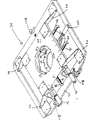
Fig. 8 is the skeleton view of alignment machine according to an embodiment of the invention;
Fig. 9 is the end-view that microscopical alignment machine has been installed on its that shows among Fig. 8;
Figure 10 is the skeleton view of the alignment machine among the Fig. 8 that is installed on the detecting plate;
Figure 11 is the end-view of Figure 10;
Figure 12 A is the structural drawing that shows the detecting plate of the flexible connector that in accordance with another embodiment of the present invention contactor assembly is electrically connected to detecting plate;
Figure 12 B is the structural drawing that shows the detecting plate of the flexible connector that according to an embodiment of the invention contactor assembly is electrically connected to detecting plate;
Figure 13 A is the side view of flexible connector among Figure 12 A;
Figure 13 B is the top plan of flexible connector end among Figure 12 A;
Figure 14 has shown the arrangement of the electric contacts on the electric contactor according to an embodiment of the invention;
Figure 15 and 16 is structural drawing of the different phase that shows that the electrical connection between the flexible electrical connector and electric contactor forms among Figure 12;
Figure 17 is the structural drawing that does not have electric connector among Figure 12 and show the detecting plate of reference mark on the contactor assembly; And
Figure 18 is the structural drawing of test probes assembly according to an embodiment of the invention.
Embodiment
Fig. 1 in the accompanying drawing has shown card extender 10 and electric contactor 26 according to an embodiment of the invention, and the two has formed contactor assembly together, is used for the electronic circuit on test case such as the wafer 32.
As shown in Figure 1, card extender 10 comprises the base plate with first side 12 and second side 14.Card extender 10 comprises some electric terminals 16 on first side 12.Card extender 10 also comprises resilient interconnection elements with the form of interconnection spring element 18.Each interconnection spring element 18 electric terminal on 12 16 from the side extends and ends at free end.The effect of each interconnection spring element 18 is that corresponding electric terminal has good electrical contact on feasible and the electric contactor 26.In other embodiments, resilient interconnection elements comprises spring needle and soft (compliant) conducting block.
Card extender comprises that also mechanical alignment stops 22 on side 12 and 14 is to prevent the interconnect over travel of spring element 18 and some zone that prevents card extender contact wafer 32.
Wafer 32 is shown as and comprises side 34, and described side 34 has electronic circuit to be tested.Wafer 32 has the electric terminal 36 on the side 34, can carry out and being electrically connected of described electronic circuit by described electric terminal 36.
Fig. 2 has shown contactor assembly 40 according to an embodiment of the invention.Described assembly 40 comprises card extender 10 and the fixation kit that exists with annulation 42 forms.Card extender is fixed on being scheduled to or aligned position with respect to electric contactor 26 by annulation 42.Can see that at described predetermined or aligned position, each interconnection spring element 18 produces distortion to electrically contact with the corresponding electric terminal 30 of electric contactor 26 corresponding to elastic force.Reach described precalculated position by mobile annulation 42 and the card extender 10 that wherein holds up to the side 28 that alignment stops 22 is run into electric contactor 26.In other embodiments, when interconnection spring element 18 (perhaps spring needle among other embodiment or soft conducting block) reaches described precalculated position when applying enough pressure, be positioned at appropriate position to keep in touch device 26.Therefore block 22 is optional.Space between card extender 10 and the electric contactor 26 is the length of each compressed interconnection spring element 18.
Fig. 3 has shown the phase one in the formation of contactor assembly 40.With reference to figure 3, evacuated panel 50 releasably be fixed to annulation 42 with respect to a surface side of 46 to form subassembly 51.Evacuated panel 50 can be connected to the pump (not shown) by hookup 54 and the flexible pipe 52 that is connected to hookup 54.During use, the zone 56 of pump between evacuated panel 50 and card extender 10 forms vacuum.This vacuum remains on sunk surface 44 with card extender 10.Shown in Figure 4 and 5, evacuated panel 50 is shaped so that the passage of fitting piece 43 to be provided.
Fig. 6 shown with among Fig. 5 along the cut-open view of 6-6 subassemblies 51 that obtain, as shown in Figure 6, card extender 10 is close to and is contained in the annulation 42.
Fig. 7 has shown the structural drawing of the alignment that how to realize card extender 10 and electric contactor 26.Card extender 10 is contained in the annulation 42 and moves on x, y or θ direction, thereby the reference mark 60 on the side 28 of the reference mark 58 on the side 12 of card extender 10 and electric contactor 26 is alignd.In case reference mark 58 is alignd with reference mark 60, annulation 42 with card extender 10 at Z direction superior displacement so that contact with contactor 26.Bolt 43 spirals that are arranged in hole 48 then enter the thread groove 68 of the complementation of electric contactor 26 formation.Reference mark 58,60 makes the electric terminal 30 on the electric contactor 26 align with interconnection spring element 18, and needn't be careful interconnection spring element 18.Each interconnection spring element in the x-y plane the position or do not influence described alignment procedure from the deviation of the firing angle on x-y plane.Electromechanical stop 22 on the side 18 of card extender 10 can be when forming assembly 40 restriction card extender 10 towards the moving of electric contactor 26, thereby each interconnection spring element 18 is in required compression.
Fig. 8 has shown the skeleton view of alignment machine 70 according to an embodiment of the invention, can be used for the combination of annulation 42 and card extender 10 is alignd with electric contactor 26.Alignment machine 70 comprises pedestal 72, and its geomery is for can place (see figure 10) on the detecting plate 152, and described detecting plate 152 can hold electric contactor 26 (seeing Figure 12 A) in use.Alignment machine 70 also comprises the platform or the flat board 74 of rise, and described platform or dull and stereotyped 74 is fixed to pedestal 72 by mounting bracket 76.Platform 74 Support brackets 78.Carriage 78 can be seen Fig. 9, has wherein shown the side view of alignment machine 70.Carriage 78 is fixed to the downside of platform 74 by the erecting device that comprises cantilever 88 and horizontal spring 90.Cantilever 88 is fixed to platform 74 and for an end of spring 90 provides support a little, the other end of spring 90 is fixed to the float plate 80 of carriage 78, as shown in Figure 9.
Carriage 78 further comprises the toroidal support 82 of the float plate 80 that is fixed to vertical member 84, and described vertical member 84 extends between toroidal support installing plate 82 and float plate 80.
The roller bearing 94 that is arranged between platform 74 and the float plate 80 allows float plate 80 slidably to place with respect to platform 74.Uprighting spring 95 forces float plate 80 contact roller bearings 94.Being appreciated that float plate 80 installs to be provided with for the spring of platform 74 can allow float plate 80 to move in the x-y plane.Moving through in such x-y plane adjusted parts and controlled, described adjustment parts comprise micrometer 96,98 and 100 in one embodiment, each micrometer can act on and force the one end to bear the edge of float plate 80, thereby causes the displacement of float plate 80.For example, as shown in Figure 9, an end 98.1 of micrometer 98 can be shifted with the edge of carrying float plate 80 in the y direction, thereby makes float plate 80 at y direction top offset.Because toroidal support 82 is connected to float plate 80 rigidly, the displacement of float plate 80 also can make correspondingly displacement of toroidal support 82.
During use, the suction by evacuated panel 50 and pump (not shown) assist in generating is fixed on the toroidal support 82 that card extender 10 in the annulation 42 is mechanically connected to carriage 78.Subsequently, alignment machine 70 places on the detecting plate 152 as shown in figure 10.In this position, annulation 42 and be fixed on the top that card extender 10 in the annulation 42 is located immediately at the electric connector 26 that is fixed in the detecting plate 152.
Can see the amplification system that comprises microscope 102 that is fixed to platform 74 among Fig. 9, described microscope 102 comprises visor parts 104 and base 106.
Microscope 102 amplifies the reference mark 58,60 on card extender 10 and the electric connector 26 respectively. Micrometer 96,98 and 100 can be worked with movable support bracket 78 then, described carriage 78 is with its carries annular thing 42 and card extender 10, thereby card extender 10 can be positioned at the predetermined or aligned position of electric connector 26 tops, and wherein the reference mark 58,60 on card extender 10 and the electric contactor 26 is alignd respectively.
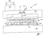
In case annulation 42 and card extender 10 are fixed to electric contactor 26, evacuated panel 50 and alignment machine 70 promptly are removed.Detecting plate 152 comprises external interface assembly 164, and described external interface assembly 164 comprises that a plurality of shapes are the electric connector of acusector pin 166, shown in Figure 12 A.Flexible connector 110 is electrically connected to interface module 164 with contactor assembly 40, and described interface module 164 is electrically connected to the burn-off chamber (not shown) of test machine subsequently by stitch 166.
Typically, piece 118.1,118.2 usefulness gold forms, and has about 100 microns width and about 60 microns height.Because gold can oxidation and can be born 150 ℃ to 350 ℃ temperature, so it is the preferred material of piece 118.Further, gold keeps its elasticity in 180 ℃ to 240 ℃ temperature range.Flexible connector 110 comprises layer 119, and described layer 119 covers line conductor 114.1 and 114.2.Layer 119 is made by non-conductive flexible material, as shown in figure 15.
Figure 15 has shown the structural drawing in the formation stage of the electrical connection between flexible connector 110 and the electric contacts 120.
Basically, in order to form the electrical connection between flexible connector 110 and the electric contactor 26, use clamp with second end, 116 clamps of flexible electrical connector 110 to electric contactor 26.Described clamp comprises first clamp members that occurs with metal elongated bars 122 forms of work hardening, and by second clamp members of electric contactor 26 decisions.The coefficient of thermal expansion coupling of the coefficient of thermal expansion of bonding jumper 122 and electric contactor 26.In one embodiment, the coefficient of thermal expansion of bonding jumper 122 is in 0.5ppm/ ℃ of the coefficient of thermal expansion of electric contactor 26.
Because set bolt 124, bonding jumper 122 and conducting block 118.1 may have different coefficient of thermal expansions with 118.2, and because the high temperature that reaches during the burn-in testing, set bolt 124 may be elongated during burn-in testing.This has caused the top 124.1 of set bolt 124 and the gap between the bonding jumper 122.
Be appreciated that such gap can reduce set bolt 124 and be applied to clamp power on the flexible connector 110.In order to compensate the trend that described gap produces, can or sandwich the expansion member 128 that resilient material is made in elongate metal bar 122 and flexible connector 110 middle insertions, as shown in figure 16.Be compressed under the clamp power effect that described expansion member 128 produces when set bolt 124 screws, and when set bolt 124 is elongated, can discharge or expand.Therefore, expansion member 128 has occupied any gap between top 124.1 and the bonding jumper 122, thereby has kept the clamp power of set bolt 124.Described expansion member is made by bearing in the burn-off chamber material of high temperature.Further, because the height of conducting block 118.1 and 118.2 may change, expansion member 128 makes flexible plate 112 discrepant distortion with compensation conducting block 118.1 and 118.2 variation highly.
Figure 12 A has shown another embodiment 110A of flexible connector.Except its every end has the conducting block that is similar to piece 118.1 and 118.2, flexible connector 110A and flexible connector 110 are similar.The end of flexible connector 110A as top described clamp to electric contactor 26, and clamp is to connector 121 in a similar manner in the opposite end of flexible connector 110A, and described connector 121 transmits electric signal and transmits electric signal to external interface 164 or from external interface.
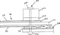
Figure 18 has shown the parts of test probes assembly 150 according to an embodiment of the invention.Test probes assembly 150 comprises detecting plate 152 and clamping plate 154, and the two defines space therebetween together, and this space is used to hold contactor assembly, for example the contactor assembly shown in Fig. 2 40.
During use, air is introduced in the chamber 160 forcing piston 158 to move in the z direction by flexible pipe 162, thereby makes contactor assembly 40 touch the side 34 of wafer 32 towards the mechanical alignment stops 22 of clamping plate 154 displacements on the side 14 of card extender 10.Form between annulation 42 and the clamping plate 154 is that the mobile contactor assembly 40 that makes that limits or control by piston 158 produces great displacement for the effect of the elastically deformable member of O shape ring 163.Therefore, moving of piston 158 do not need accurate control.Further, O shape ring 163 sealings that provide between annulation 42 and the clamping plate 154.O shape ring 163 is by being that annulation 42 adds that surface 46 that liner allows annulation 42 is not in the deviation of identical z-plane during towards clamping plate 154 displacements at annulation 42.In one embodiment, O shape ring 163 can replace the reacting force that spring can provide piston 158 to move with spring.In case the electromechanical stop 22 on the side 14 of card extender 10 touches the side 34 of wafer 32, the interconnection spring element is compressed with the good electrical contact between the electric terminal 36 of interconnection spring element 20 that reaches card extender 10 and wafer 32.Subsequently, flexible pipe 162 is removed.Probe assembly 152 also comprises fixed member, is used for loosely clamping plate 154 being fixed to detecting plate 152.Described fixed member is not presented among Figure 12, but comprise any suitable gripping mechanism, and for example U.S. Patent No. 6,340, and the motion hookup in 895 is incorporated into this with it as a reference.Test probes assembly 150 is inserted in the test burn-in chamber then, wherein is electrically connected stitch 166 and is contained in the complementary electrical slot.
Although the present invention is described with reference to specific example embodiment, yet obviously can carries out various modifications and change and do not deviate from the essence widely of the present invention that proposes in claims these embodiment.Therefore, this instructions and accompanying drawing should be considered to the example meaning but not limited significance.
Claims (23)
1. one kind is used for test component is electrically connected to test machine with the device to the testing electrical circuits on the test component, and described device comprises:
Contactor assembly comprises a plurality of first conductors; A plurality of the first terminals, each described the first terminal are connected to corresponding described first conductor; A plurality of resilient interconnection elements, each described resilient interconnection elements are connected to corresponding described first conductor, and have the end that electrically contacts described test component; And the supporting component that is used to support described contactor assembly;
Be positioned at the external interface assembly on the described supporting component, comprise that electric connector is used for being electrically connected with described test machine;
Flexible plate;
Be positioned on the described flexible plate and be electrically connected to flexibility second conductor of described external interface assembly;
A plurality of second terminals that are electrically connected to described flexible second conductor on the described flexible plate;
The a plurality of conducting blocks that are provided with between described first and second terminals; And
The clip that comprises first and second clamp members is used to force described first and second terminals adjacent to each other and make described conducting block produce deformation.
2. device according to claim 1, wherein each described the first terminal comprises the terminal bodies with straight surface of contact.
3. device according to claim 2, wherein said first clamp members comprises the elongate metal bar that extends beyond a conducting block.
4. device according to claim 3, wherein said bonding jumper are the work hardening metals that hardened steel is made.
5. device according to claim 3, wherein said second clamp members comprises the set bolt that is used for described bonding jumper is pushed to the surface of contact of described each terminal bodies.
6. device according to claim 5, it further comprises the expansion member in the described clip, wherein said expanding material is resilient material and is in the compression, and with the parallel direction of described set bolt the reducing of the clamp power that causes owing to described set bolt is elongated with compensation of expanding.
7. device according to claim 1, wherein said conducting block is made of gold.
8. device according to claim 1, wherein said conducting block have 60 microns height and 100 microns width.
9. device according to claim 8, wherein said expansion member comprises silicon rubber.
10. device according to claim 4, the maintenance assembly that electrically contacts that wherein said contactor assembly comprises card extender, electric contactor and keeps described card extender and electric contactor, wherein said a plurality of first conductor and the first terminal are positioned on the described electric contactor, described a plurality of interconnection spring element is positioned on the described card extender, and wherein said electric contactor and flexible plate comprise that reference mark on it is to help described first and second terminals of alignment.
11. device according to claim 10, the coefficient of thermal expansion of wherein said bonding jumper mate in 0.5ppm/ ℃ of the coefficient of thermal expansion of described contactor base plate.
12. device according to claim 10, wherein said electric contactor and described card extender have complementary reference mark to help the electric contacts on described resilient interconnection elements of alignment and the described electric contactor.
13. device according to claim 1, wherein said resilient interconnection elements comprises spring.
14. one kind is used for test component is electrically connected to test machine with the proving installation to the testing electrical circuits on the test component, described proving installation comprises:
Contactor assembly, comprise first electric conductor, be connected to a plurality of the first terminals of first end of described first electric conductor, be connected to a plurality of second terminals of second end of described first electric conductor, and the resilient interconnection elements that described the first terminal is electrically connected to described test component;
Probe assembly comprises the board component that supports described contactor assembly, and the interface module on the described board component, and described interface module comprises a plurality of external electric connectors that are used to be electrically connected to described test machine; Have first end that is connected to described interface module and with the flexible plate of the first end second opposed end, fexible conductor on the described flexible plate, described fexible conductor has the stem that is connected to described interface module and in the end at the second end place of described flexible plate, described end comprises a plurality of the 3rd terminals that align with described second terminal;
A plurality of electric contactor pieces between the described second and the 3rd terminal; And
The clamp parts that comprise first clamp members and second clamp members, described clamp members are suppressed together and to apply clamp power the described second and the 3rd terminal are moved together, thereby make contactor piece therebetween produce deformation.
15. proving installation according to claim 14, wherein said resilient interconnection elements comprises spring.
16. proving installation according to claim 14, wherein said first clamp members comprises that bonding jumper and described second clamp members comprise the surface in contact of each second terminal, and described clamp parts comprise that further set bolt and complementary nuts are to push described bonding jumper to described the 3rd terminal.
17. proving installation according to claim 15, wherein said clamp parts further comprise the expansion member between described set bolt top and described nut, described expansion member is made by the resilient material that is in the compression, and expands with compensation reducing owing to the elongated clamp power that causes of described set bolt along described set bolt axis.
18. proving installation according to claim 17, wherein said contactor assembly comprises electric contactor, described a plurality of first electric conductor, a plurality of the first terminal and a plurality of second terminal position thereon, described electric contactor and flexible plate have complementary reference mark to help alignment the described second and the 3rd terminal.
19. proving installation according to claim 18, wherein said conducting block are linked to described the 3rd terminal.
20. one kind is used for test component is connected to test machine with the unit to the testing electrical circuits on the test component, described unit comprises:
Supporting component is used to support contactor assembly to electrically contact with described test component, and wherein said contactor assembly comprises: a plurality of first conductors; A plurality of the first terminals, each described the first terminal are connected to corresponding described first conductor; A plurality of resilient interconnection elements, each described resilient interconnection elements are connected to corresponding described first conductor, and each described resilient interconnection elements has the end that electrically contacts described test component; And the supporting component that is used to support described contactor assembly;
External interface assembly on the described supporting component comprises a plurality of electric connectors that are used to be electrically connected to described test machine;
Flexible plate, have first end that is electrically connected to described interface module and with the described first end second opposed end;
Fexible conductor on the described flexible plate, described fexible conductor has the stem that is electrically connected to described interface module and in the end at the second end place of described flexible plate, described end comprises a plurality of terminals and a plurality of conducting block, each described conducting block is connected to a corresponding described terminal, and wherein said end can be connected to described contactor assembly and transmit electric signal between described contactor assembly and described test machine.
21. unit according to claim 20, wherein two conducting blocks are connected to each terminal by the lead-in wire connected mode.
22. unit according to claim 21, wherein said conducting block is made of gold.
23. unit according to claim 22, wherein said conducting block have 100 microns width and 60 microns height.
Applications Claiming Priority (4)
| Application Number | Priority Date | Filing Date | Title |
|---|---|---|---|
| US10/197,104 US6867608B2 (en) | 2002-07-16 | 2002-07-16 | Assembly for electrically connecting a test component to a testing machine for testing electrical circuits on the test component |
| US10/197,133 US6853209B1 (en) | 2002-07-16 | 2002-07-16 | Contactor assembly for testing electrical circuits |
| US10/197,104 | 2002-07-16 | ||
| US10/197,133 | 2002-07-16 |
Publications (2)
| Publication Number | Publication Date |
|---|---|
| CN1668929A CN1668929A (en) | 2005-09-14 |
| CN100523826C true CN100523826C (en) | 2009-08-05 |
Family
ID=30117843
Family Applications (1)
| Application Number | Title | Priority Date | Filing Date |
|---|---|---|---|
| CNB038166755A Expired - Fee Related CN100523826C (en) | 2002-07-16 | 2003-07-15 | Assembly for electrically connecting a test component to a testing machine for testing electrical circuits on the test component |
Country Status (6)
| Country | Link |
|---|---|
| EP (1) | EP1523685A2 (en) |
| JP (1) | JP2005533254A (en) |
| KR (1) | KR20050029215A (en) |
| CN (1) | CN100523826C (en) |
| AU (1) | AU2003249276A1 (en) |
| WO (1) | WO2004008163A2 (en) |
Families Citing this family (17)
| Publication number | Priority date | Publication date | Assignee | Title |
|---|---|---|---|---|
| KR100956472B1 (en) | 2005-04-27 | 2010-05-07 | 에어 테스트 시스템즈 | Appratus for testing electronic devices |
| CN101051067B (en) * | 2006-04-03 | 2010-08-11 | 航天科工防御技术研究试验中心 | Comprehensive detection control device design method for electric connector |
| MY152599A (en) | 2007-02-14 | 2014-10-31 | Eles Semiconductor Equipment S P A | Test of electronic devices at package level using test boards without sockets |
| EP1959265A1 (en) * | 2007-02-16 | 2008-08-20 | Eles Semiconductor Equipment S.P.A. | Testing integrated circuits on a wafer with a cartridge leaving exposed a surface thereof |
| US7557594B2 (en) * | 2007-08-14 | 2009-07-07 | Electro Scientific Industries, Inc. | Automated contact alignment tool |
| US7800382B2 (en) | 2007-12-19 | 2010-09-21 | AEHR Test Ststems | System for testing an integrated circuit of a device and its method of use |
| CN101545926B (en) * | 2008-03-25 | 2011-05-11 | 旺矽科技股份有限公司 | Probe testing device |
| DE102009012021B4 (en) * | 2009-03-10 | 2011-02-03 | Fraunhofer-Gesellschaft zur Förderung der angewandten Forschung e.V. | Measuring device for the electrical measurement of a measurement structure that can be electrically contacted on one side of a measurement side |
| TWI440412B (en) * | 2011-12-28 | 2014-06-01 | Princo Corp | Package method of thin multi-layer substrate |
| CN103808969A (en) * | 2012-11-08 | 2014-05-21 | 富泰华工业(深圳)有限公司 | Tool for bearing to-be-tested electronic device |
| CN103808979A (en) * | 2012-11-08 | 2014-05-21 | 富泰华工业(深圳)有限公司 | Tool for bearing to-be-tested electronic device |
| CN105548859A (en) * | 2015-12-09 | 2016-05-04 | 上海精密计量测试研究所 | Testing equipment and method for environment testing |
| CN106200239B (en) * | 2016-09-14 | 2019-03-15 | 海信集团有限公司 | Ray machine lighting system |
| US10782316B2 (en) * | 2017-01-09 | 2020-09-22 | Delta Design, Inc. | Socket side thermal system |
| EP4290243A3 (en) | 2017-03-03 | 2024-02-28 | AEHR Test Systems | Electronics tester |
| US11835575B2 (en) | 2020-10-07 | 2023-12-05 | Aehr Test Systems | Electronics tester |
| KR20240027784A (en) | 2021-06-30 | 2024-03-04 | 델타 디자인, 인코포레이티드 | Temperature control system including contactor assembly |
Family Cites Families (5)
| Publication number | Priority date | Publication date | Assignee | Title |
|---|---|---|---|---|
| US5148103A (en) * | 1990-10-31 | 1992-09-15 | Hughes Aircraft Company | Apparatus for testing integrated circuits |
| JPH0763788A (en) * | 1993-08-21 | 1995-03-10 | Hewlett Packard Co <Hp> | Probe, electrical part / circuit inspecting device and electrical part / method of circuit inspection |
| US6028437A (en) * | 1997-05-19 | 2000-02-22 | Si Diamond Technology, Inc. | Probe head assembly |
| US6137297A (en) * | 1999-01-06 | 2000-10-24 | Vertest Systemsn Corp. | Electronic test probe interface assembly and method of manufacture |
| JP2001013208A (en) * | 1999-06-30 | 2001-01-19 | Mitsubishi Electric Corp | Semiconductor-testing tool |
-
2003
- 2003-07-15 KR KR1020057000799A patent/KR20050029215A/en not_active Application Discontinuation
- 2003-07-15 CN CNB038166755A patent/CN100523826C/en not_active Expired - Fee Related
- 2003-07-15 WO PCT/US2003/022125 patent/WO2004008163A2/en active Application Filing
- 2003-07-15 EP EP03764698A patent/EP1523685A2/en not_active Withdrawn
- 2003-07-15 AU AU2003249276A patent/AU2003249276A1/en not_active Abandoned
- 2003-07-15 JP JP2004521866A patent/JP2005533254A/en active Pending
Also Published As
| Publication number | Publication date |
|---|---|
| WO2004008163A3 (en) | 2004-06-10 |
| CN1668929A (en) | 2005-09-14 |
| KR20050029215A (en) | 2005-03-24 |
| WO2004008163A2 (en) | 2004-01-22 |
| JP2005533254A (en) | 2005-11-04 |
| AU2003249276A1 (en) | 2004-02-02 |
| AU2003249276A8 (en) | 2004-02-02 |
| EP1523685A2 (en) | 2005-04-20 |
Similar Documents
| Publication | Publication Date | Title |
|---|---|---|
| CN100523826C (en) | Assembly for electrically connecting a test component to a testing machine for testing electrical circuits on the test component | |
| US7511521B2 (en) | Assembly for electrically connecting a test component to a testing machine for testing electrical circuits on the test component | |
| US8134381B2 (en) | Connection board, probe card, and electronic device test apparatus comprising same | |
| US20050184745A1 (en) | Probe card | |
| KR100915643B1 (en) | Probe card | |
| US7541820B2 (en) | Probe card | |
| US20080284458A1 (en) | Method for Forming Connection Pin, Probe, Connection Pin, Probe Card and Method for Manufacturing Probe Card | |
| US7815473B2 (en) | Contact and connecting apparatus | |
| KR100975808B1 (en) | The fixture for circuit board inspection | |
| WO2005069019A1 (en) | Probe guard | |
| US7301358B2 (en) | Contactor assembly for testing electrical circuits | |
| KR101104287B1 (en) | Probe card | |
| KR102159672B1 (en) | Probe and Probe Block Using the Same | |
| US10712383B2 (en) | Inspection jig | |
| KR101147573B1 (en) | Semiconductor testing apparatus | |
| JP5643476B2 (en) | Double elastic mechanism probe card | |
| JP5244288B2 (en) | Inspection device | |
| TW201825917A (en) | Probe card assembly having die-level and pin-level compliance, and associated systems and methods | |
| KR100725456B1 (en) | Probe card for wafer test | |
| CN111751584A (en) | Electrical contact and probe card | |
| JP4056983B2 (en) | Probe card | |
| US11579170B2 (en) | Probe apparatus | |
| KR102386462B1 (en) | Probe card and apparatus for aligning thereof | |
| CN114594291A (en) | Probe apparatus | |
| KR20230076513A (en) | Probe card |
Legal Events
| Date | Code | Title | Description |
|---|---|---|---|
| C06 | Publication | ||
| PB01 | Publication | ||
| C10 | Entry into substantive examination | ||
| SE01 | Entry into force of request for substantive examination | ||
| C14 | Grant of patent or utility model | ||
| GR01 | Patent grant | ||
| C17 | Cessation of patent right | ||
| CF01 | Termination of patent right due to non-payment of annual fee |
Granted publication date: 20090805 Termination date: 20110715 |