CN100533997C - Electronic circuit and control method therefor - Google Patents
Electronic circuit and control method therefor Download PDFInfo
- Publication number
- CN100533997C CN100533997C CNB2004100749810A CN200410074981A CN100533997C CN 100533997 C CN100533997 C CN 100533997C CN B2004100749810 A CNB2004100749810 A CN B2004100749810A CN 200410074981 A CN200410074981 A CN 200410074981A CN 100533997 C CN100533997 C CN 100533997C
- Authority
- CN
- China
- Prior art keywords
- mentioned
- circuit
- sensor
- signal processing
- processing circuit
- Prior art date
- Legal status (The legal status is an assumption and is not a legal conclusion. Google has not performed a legal analysis and makes no representation as to the accuracy of the status listed.)
- Expired - Fee Related
Links
Images


Classifications
-
- H—ELECTRICITY
- H05—ELECTRIC TECHNIQUES NOT OTHERWISE PROVIDED FOR
- H05K—PRINTED CIRCUITS; CASINGS OR CONSTRUCTIONAL DETAILS OF ELECTRIC APPARATUS; MANUFACTURE OF ASSEMBLAGES OF ELECTRICAL COMPONENTS
- H05K1/00—Printed circuits
- H05K1/18—Printed circuits structurally associated with non-printed electric components
- H05K1/181—Printed circuits structurally associated with non-printed electric components associated with surface mounted components
-
- H—ELECTRICITY
- H05—ELECTRIC TECHNIQUES NOT OTHERWISE PROVIDED FOR
- H05K—PRINTED CIRCUITS; CASINGS OR CONSTRUCTIONAL DETAILS OF ELECTRIC APPARATUS; MANUFACTURE OF ASSEMBLAGES OF ELECTRICAL COMPONENTS
- H05K1/00—Printed circuits
- H05K1/02—Details
- H05K1/0213—Electrical arrangements not otherwise provided for
- H05K1/0216—Reduction of cross-talk, noise or electromagnetic interference
- H05K1/0218—Reduction of cross-talk, noise or electromagnetic interference by printed shielding conductors, ground planes or power plane
-
- H—ELECTRICITY
- H05—ELECTRIC TECHNIQUES NOT OTHERWISE PROVIDED FOR
- H05K—PRINTED CIRCUITS; CASINGS OR CONSTRUCTIONAL DETAILS OF ELECTRIC APPARATUS; MANUFACTURE OF ASSEMBLAGES OF ELECTRICAL COMPONENTS
- H05K1/00—Printed circuits
- H05K1/02—Details
- H05K1/0296—Conductive pattern lay-out details not covered by sub groups H05K1/02 - H05K1/0295
- H05K1/0298—Multilayer circuits
-
- H—ELECTRICITY
- H05—ELECTRIC TECHNIQUES NOT OTHERWISE PROVIDED FOR
- H05K—PRINTED CIRCUITS; CASINGS OR CONSTRUCTIONAL DETAILS OF ELECTRIC APPARATUS; MANUFACTURE OF ASSEMBLAGES OF ELECTRICAL COMPONENTS
- H05K2201/00—Indexing scheme relating to printed circuits covered by H05K1/00
- H05K2201/07—Electric details
- H05K2201/0707—Shielding
- H05K2201/0723—Shielding provided by an inner layer of PCB
-
- H—ELECTRICITY
- H05—ELECTRIC TECHNIQUES NOT OTHERWISE PROVIDED FOR
- H05K—PRINTED CIRCUITS; CASINGS OR CONSTRUCTIONAL DETAILS OF ELECTRIC APPARATUS; MANUFACTURE OF ASSEMBLAGES OF ELECTRICAL COMPONENTS
- H05K2201/00—Indexing scheme relating to printed circuits covered by H05K1/00
- H05K2201/10—Details of components or other objects attached to or integrated in a printed circuit board
- H05K2201/10007—Types of components
- H05K2201/10151—Sensor
-
- H—ELECTRICITY
- H05—ELECTRIC TECHNIQUES NOT OTHERWISE PROVIDED FOR
- H05K—PRINTED CIRCUITS; CASINGS OR CONSTRUCTIONAL DETAILS OF ELECTRIC APPARATUS; MANUFACTURE OF ASSEMBLAGES OF ELECTRICAL COMPONENTS
- H05K2201/00—Indexing scheme relating to printed circuits covered by H05K1/00
- H05K2201/10—Details of components or other objects attached to or integrated in a printed circuit board
- H05K2201/10613—Details of electrical connections of non-printed components, e.g. special leads
- H05K2201/10621—Components characterised by their electrical contacts
- H05K2201/10689—Leaded Integrated Circuit [IC] package, e.g. dual-in-line [DIL]
-
- H—ELECTRICITY
- H05—ELECTRIC TECHNIQUES NOT OTHERWISE PROVIDED FOR
- H05K—PRINTED CIRCUITS; CASINGS OR CONSTRUCTIONAL DETAILS OF ELECTRIC APPARATUS; MANUFACTURE OF ASSEMBLAGES OF ELECTRICAL COMPONENTS
- H05K2203/00—Indexing scheme relating to apparatus or processes for manufacturing printed circuits covered by H05K3/00
- H05K2203/15—Position of the PCB during processing
- H05K2203/1572—Processing both sides of a PCB by the same process; Providing a similar arrangement of components on both sides; Making interlayer connections from two sides
-
- Y—GENERAL TAGGING OF NEW TECHNOLOGICAL DEVELOPMENTS; GENERAL TAGGING OF CROSS-SECTIONAL TECHNOLOGIES SPANNING OVER SEVERAL SECTIONS OF THE IPC; TECHNICAL SUBJECTS COVERED BY FORMER USPC CROSS-REFERENCE ART COLLECTIONS [XRACs] AND DIGESTS
- Y02—TECHNOLOGIES OR APPLICATIONS FOR MITIGATION OR ADAPTATION AGAINST CLIMATE CHANGE
- Y02P—CLIMATE CHANGE MITIGATION TECHNOLOGIES IN THE PRODUCTION OR PROCESSING OF GOODS
- Y02P70/00—Climate change mitigation technologies in the production process for final industrial or consumer products
- Y02P70/50—Manufacturing or production processes characterised by the final manufactured product
Abstract
An electronic circuit, preferable as a sensor node, has a highly sensitive radio function and is capable of performing a low-power-consumption operation. The electronic device has a board; a connector for connecting a sensor; a first signal processor circuit receiving an input of sensor data from the sensor through the connector and forming transmission data; and a second signal processor circuit converting a transmission signal from the first signal processor circuit into a high-frequency signal. The connector and the first signal processor circuit are mounted on a first surface of the board, and the second signal processor circuit is mounted on a second surface of the board.
Description
Technical field
The present invention relates to electronic circuit with radio communication function.The electronic circuit that particularly relates to the small-sized and low consumpting power that is suitable for constructing sensor network system.
Background technology
In recent years, people are discussing by additional small circuit with radio communication function in transducer, in real time the various information of real world are taken into the network system (below, be called sensor network) of information processor.Consider application widely about sensor network, for example, also can consider by integrated radio-circuit, processor, transducer, the small circuit of the ring type of battery, invariably monitor pulse etc., to monitor that by radio communication the result is transmitted to diagnostic device, based on monitoring that the result judges the such medical applications of health status (non-patent literature 1 (Sokwoo Rhee etc. " Artifact-Resistant Power-EfficientDesign of Finger-Ring Plethysmographic Sensors ", IEEETransactions On Biomedical Engineering, Vol.48, No.7, July 2001, PP.795-805)).
But, in order to make sensor network practicability widely, the electronic circuit (below, be called sensor node) of power supplys such as carrying radio communication function, transducer and battery is safeguarded through not needing for a long time, and emission sensor data continuously, it is important that profile also reaches miniaturization.Therefore, developing because microminiature can be placed on sensor node Anywhere.In present stage, in the practicality, communicating battery ground does not use the time in about 1 year, but also needs to consider from maintenance cost and such two aspects easy to use.
Like this, requiring sensor node is microminiature low consumpting power simultaneously.For example, at non-patent literature 2 (Crossbow " Smarter Sensors In Silicon ", " online ", " retrieval on February 16th, 2004 ", internet<URL:http: //www.xbow.com/Support/Support_pdf_files/Motetraining/Hard ware.pdf 〉) in, introduced and be called " Mica2Dot ", the prototype of the Miniature Sensor node of the about 3cm of diameter.This Mica2Dot is made of the RF chip of integrated radio communication required function and the processor chips of low consumpting power.In this prototype, the time by 99% is holding state, only starts on 1% time discontinuous ground of remainder, makes working sensor, carries out the result is implemented the discontinuous operation of radio communication, can be with compact battery work about 1 year.In this sensor node, utilize as not needing to permit the frequency band of 260~470MHz, 902~928MHz etc. with regard to operable frequency band to carry out radio communication in the U.S..Generally, need to use the special transreceiver of being permitted and pass through pre-authentication, for utilizing, have very big restriction in order to carry out radio communication.Therefore, do not need the frequency of permitting because if utilize, then need not the expensive time and cost just can be provided with and easy construction systems, so be favourable with this frequency band.Particularly, maximum in U.S.'s regulation transmitting power, electric field strength is smaller or equal to 11mV/m in the 433MHz frequency band, in addition, in the 900MHz frequency band, smaller or equal to 50mV/m (all being on the place of leaving launch point 3m distance), even if in the frequency band that does not need to permit, by the frequency band that the setting that uses these transmitting powers relatively relaxes, can realize good communication performance and cost degradation.
; the electric wave rules are different because of country and region; for example; the electric wave rules such as the non-patent literature 3 (" く さ ん makes the little No Line of わ れ て い Ru Machine device " " online " " retrieval on February 17th, 2004 " of Japan; internet<URL:http: //www.circuitdesign.jp/jp/technical/technical_pdf/bijaku.p df.PDF 〉) middle record and narrate such, in the frequency band that does not need to permit, also not necessarily relax the electric field strength that allows.
Again, in non-patent literature 4 (" Data Sheet CR2032 " " online " " retrieval on February 21st, 2004 ", internet<URL:http: //www.maxell.co.jp/e/products/industrial/battery/pdf/CR203 2_DataSheet.pdf 〉) in, the miniature button cell that is suitable for as the power supply of sensor node is disclosed.
Summary of the invention
According to the present invention, a kind of electronic installation is provided, comprising: connector is used to connect transducer; The 1st signal processing circuit receives the sensing data of importing via above-mentioned connector from the sensor, forms according to the sensor data and sends data; The 2nd signal processing circuit will become high-frequency signal from the above-mentioned transmission data conversion of above-mentioned the 1st signal processing circuit; Imput output circuit receives the input of above-mentioned high-frequency signal, via antenna it is exported; And substrate, have first and above-mentioned the 2nd signal processing circuit of installation and above-mentioned imput output circuit second that above-mentioned connector and above-mentioned the 1st signal processing circuit are installed, wherein, above-mentioned first and above-mentioned second face become the surface and the back side of aforesaid substrate, so that the signal path between above-mentioned the 1st signal processing circuit and above-mentioned the 2nd signal processing circuit turns back.
Different because of country and region of essential electric wave resource (operable frequency band and maximum transmission power) as shown in the non-patent literature 3, do not need to permit as follows with regard to operable electric wave resource in Japan in the radio communication.
1. smaller or equal to 322MHz or more than or equal to the frequency band of 10GHz
On the distance of leaving launch point 3m, electric field strength is smaller or equal to 500 μ V/m
2. more than or equal to 322MHz and smaller or equal to the frequency band of 10GHz
On the distance of leaving launch point 3m, electric field strength is smaller or equal to 35 μ V/m.
This limits value is severe more than the limits value of the U.S..Therefore, the sensor node that designs in order to use the supposition high transmit power in severe electric wave restriction environment must make transmitting power ratio set point originally low., because be merely able to receive the low power of supposing more than original of power, so can not work well in reception one side.For example, if limit the sensor node that uses according to the electric wave limit design of the U.S., then in the situation of 900MHz frequency band, transmitting power must be cut to 35 μ V/m from 50mV/m according to the electric wave of Japan.That is, received-signal strength also must weaken 63dB (=20 * log (50mV/0.035mV)).
Minimum receiving sensitivity in general RF chip (minimum value of the signal level of the high-frequency wireless signals that can receive) is about-100dBm.When received-signal strength also weakens 63dB, may receive hardly.Specifically, exist on the distance that is trapped in several 10m transceiving device stably, even if the worry of the state of affairs that on the distance of number m, can not communicate.If the frequency of using is altered to 315MHz, then because allow 500 μ V/m, so what can improve situation as electric field strength.,, also worsened 40dB (=20 * log (50mV/0.5mV)), that is, can not avoid the deterioration of the distance that can communicate by letter even if in this case.
In order to improve receiving sensitivity, at first will make the RF chip have more high sensitivity, but let us think that it is difficult sensitivity will being brought up to more than this with the CMOS technology of present status.Therefore, (Low NoiseAmplifier LNA) appends to the input of RF chip to the high frequency low noise amplifier of implementing widely to add, and improves sensitivity of method.If by additional this amplifier, make the signal of reception amplify about 20dB, then in theory, can think the communication distance that can reach about 10m.
But, just so still inadequate in our actual tentative scope.Usually, in sensor node, because the restriction of size must be integrated in very little zone (~number cm angle) with processor chips and RF chip.On the other hand, such as everyone knows, as sensor node, carrying out in the situation of radio communication with faint high-frequency wireless signals, the radiated noise of from processor chip becomes to be hindered, and can not improve receiving sensitivity simply.Usually, digital circuit square wave switching signal.Square wave is made of the AC signal of all frequency contents, is comprising the extremely approaching signal of frequency band in the signal component that wherein uses in radio communication.On the other hand, in the RF chip, amplify very faint high-frequency wireless signals (typically smaller or equal to μ V magnitude), desired data are carried out demodulation.Therefore, even if the signal of digital circuit seldom, when getting back to the importation of RF chip, in the RF chip, can not normally carry out demodulation to high-frequency wireless signals from antenna.Further, even if diverse at first sight frequency content, by the input and output nonlinear characteristic of amplifying circuit LNA and the semiconductor device that uses in the RF chip internal, the signal of the synthetic frequency content that makes new advances noise signal occurred in the frequency band that receives object.Therefore, in the worst situation, what probably the amplifier LNA that appends in order to improve receiving sensitivity amplified is the radiated noise of from processor chip.So, in sensor node, must solve miniaturization and improve such two the opposite problems of receiving sensitivity.
In addition, adopt amplifier LNA that consumed power and then battery life are exerted an influence.Make amplifier LNA chip integral body be in holding state even if in amplifier LNA, possessing when use, suppress the function of consumed power, at the standby current of the about 10 μ A of holding state also maximum consumption.For to make sensor node be maintenance-free and can work for a long time, have to use button cell in the state of compactness.But the current capacity of this button cell etc. has only 200mA at most.Therefore, when in amplifier LNA, often consuming the electric current of about 10 μ A, be not merely able to continue about 2 years (2.28=200mAh/0.01mA/24h/365 days) even if do not carry out any work yet.In fact reduce according to the condition battery capacity, for example during low temperature battery capacity to reduce be well-known, this has further shortened battery life.
From battery life viewpoint its using method importantly.Shown in non-patent literature 4 like that, when in button cell, during the big electric current of continuous flow exceedance mA, battery capacity is worsened terrifically.Further, the inventor finds when using button cell by checking, do not suppress peak current even if use in the situation of button cell in (off and on) pulsedly, thereby makes the such problem of the extreme deterioration of battery capacity.In inventor's actual measurement, when consuming the electric current of about 10mA pulsedly, also observe same phenomenon.In sensor node so far, for example shown in the non-patent literature 2 like that, by duty ratio (in discontinuous operation, the running time and the ratio in the intermittently used time interval) is suppressed to smaller or equal to 1%, can reach the purpose that reduces the average consumed cur-rent extending battery life.So, reduce the mode that duty ratio is subdued average consumed cur-rent, because when producing big peak current, battery capacity is extremely worsened, so exist the worry that shortens battery life on the contrary.
In the RF chip that can realize with the semiconductor technology of present status, in receiving, emission needs the electric current of about 10mA, also need the electric current of about 5mA for the processor slice work that makes low consumpting power.Further, the electric current that in amplifier LNA, also needs 10mA.So in emission receives, need as a whole, the electric current of about 20mA.Therefore, as non-patent literature 2 disclosed, the low duty ratio with about 0.1% carried out work, even if the current sinking on apparent is suppressed to about 10 μ A, in fact exist because the deterioration phenomenon of the button cell capacity that causes by peak current, and make the worry that the life-span shortens considerably.Further, when considering the current sinking of transducer, actual battery life becomes shorter.In general sensor network is used,, can consider temperature sensor, acceleration transducer, optical pickocff etc. as transducer.Wherein, temperature sensor can obtain number μ A.But, in the pulse transducer of the optical pickocff that in non-patent literature 1, discloses, need the electric current of peak value mA.In addition, even if the current sinking of temperature sensor is number μ A, when often starting as before, because the current capacity of button cell is limited, so can not ignore the influence (, also only continuing 200mAh/5 μ A/24h/365 days=4.5 years) that gives working life even if in the situation of 5 μ A.
Therefore, according to the present invention, by doing one's utmost to get rid of The noise is improved actual effect by amplifier LNA receiving sensitivity, one side does one's utmost to suppress standby current simultaneously, one side also is suppressed at low value with peak current, reduce the deterioration phenomenon of the battery capacity of button cell, the sensor node of small-sized and long-life practicality is provided.
Further, in the present invention, by in sensor node, for extending battery life to greatest extent, synthetically a few NA/ transducers of processor controls chip/RF chip provide and standby current and peak current can be suppressed to minimal control mode.
Representational characteristics of the present invention are as follows.Electronic installation of the present invention has substrate, is used to connect the connector of transducer, passes through connector is accepted input from transducer transducer transmission of data, form the 1st signal processor circuit of emission data and will be transformed into the 2nd signal processor circuit of high-frequency signal from transmitting of the 1st signal processor circuit, connector and the 1st signal processor circuit are installed on the 1st of substrate, the 2nd signal processor circuit are installed on the 2nd of substrate.Therefore, the digital circuit that becomes noise-producing source is separated with high-frequency circuit.In order further to improve this effect, the noise shielding layer is set on substrate.Further, also work hard on all away from circuit that becomes noise-producing source and circuit to noise-sensitive in the configuration that makes each face.
Again, electronic installation has the discontinuous operation of carrying out, and can block the formation of the power supply that does not use circuit.For example, do not block power supply when high frequency low noise amplifier LNA does not receive work, the power supply that is truncated to transducer when reading work is supplied with.
Further, for having the button cell of using supply power, can implement inter-process simultaneously and receive the electronic installation of the formation of handling with the emission of external device (ED), when judging that the required current sinking of inter-process surpasses the scheduled current amount with the required current sinking sum of emission reception processing, implement above-mentioned inter-process and emission reception processing in different timings, when judging that current sinking that inter-process is required and emission receive when handling required current sinking sum and being no more than the scheduled current amount, implement inter-process and emission in the timing that repeats and receive and handle.Because battery life is worsened, so want presumptive current sinking decision work timing.
According to the present invention, can realize having practical communication distance performance, have the sensor node of practical working life.
Description of drawings
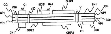
Fig. 1 is the figure of an execution mode (surface) of expression sensor node.
Fig. 2 is the figure of an execution mode (back side) of expression sensor node.
Fig. 3 is the figure of an execution mode (cross section) of expression sensor node.
Fig. 4 is the figure that expression is arranged on the ground plane layer in the substrate inside.
Fig. 5 is the figure that expression is arranged on the power plane layer in the substrate inside.
Fig. 6 is the figure of the details of expression interface IF1.
Fig. 7 is the figure of the configuration example of expression LED display monitor.
Fig. 8 is the figure of configuration example of the control circuit of expression HF switch and amplifier LNA.
Fig. 9 is the figure that is illustrated in the signal flow among the sensor node SN1.
Figure 10 (a)~(e) represents that respectively the power supply that can use blocks the figure of the configuration example of switch in sensor node SN1.
Figure 11 is used for and can makes sensor node carry out the flow diagram of the Poewr control method of work by low consumpting power.
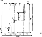
The figure of example of the current sinking waveform of the sensor node that Figure 12 is expression when the Poewr control method of application Figure 11.
The figure of example of the current sinking waveform of the sensor node that Figure 13 is expression when the Poewr control method of application Figure 11.
Figure 14 is the figure of comparative example of the current sinking waveform of the sensor node of expression when not using the Poewr control method of Figure 11.
Figure 15 is expression and the combine figure of the configuration example that the power supply board that uses and program write substrate of sensor node of the present invention.
Figure 16 is the figure of expression with the configuration example of the sensor node system of sensor node realization of the present invention.
Figure 17 is the figure that is illustrated in the sensor node system of Figure 16 from the configuration example of the data of sensor node emission of the present invention.
Label declaration
SN1...... sensor node, SIDE1...... the 1st of substrate the, SIDE2...... the 2nd of substrate the, CA, CB, CC, CD...... 4 of substrate angles, CHIP1, CHIP2...... semiconductor integrated circuit, C1, C2, C3, C4...... electric capacity, X1, X2, X3...... quartz vibrator or ceramic vibrator, ANT1...... antenna, LNA...... high frequency low noise amplifier, RFSW...... HF switch, MA...... high-frequency resistance match circuit, RF...... high-frequency circuit (comprises data modem, PLL, VCO etc.), OSC...... oscillating circuit, CON...... control circuit, the DISP......LED display monitor, CPU...... processor circuit, the ADC......A/D translation circuit, MEM, CMEM1...... memory, SIO...... serial communication circuit, TM1...... timer circuit, PIO...... programmable imput output circuit, the control circuit of LSC......RFSW/LNA, PS1, PS2, PS11, PS21, PS22...... power supply blocks switch, TS...... temperature sensor, CN1, CN2, CN3...... connector, VDD...... the 1st power line, VDD2...... the 2nd power line, VDD3...... the 3rd power line, the GND earth potential, IF1...... interface, V1, V2, V3, V4, V5, V6, V7, V10, V11, V13, V15, V21, V22, V23...... be used for the plating layer (through hole) that is connected with the inside with the surface of substrate, DS...... data signal line, CS...... control signal wire, the control signal wire of DC......LED display monitor, the reset signal line of RES......CHIP2, AP......A/D figure signal line, DP...... numeral I/O holding wire, AT...... temperature sensor output signal line, VP1...... be arranged on the 1st bus plane of substrate inside, GP1...... is arranged on the ground plane of substrate inside, VH10, VH11, VH13, VHI1, VH15...... in order to be arranged on the zone among the GP1 by plating, VH20, VH21, VH22, VH23, VHI1...... in order to be arranged on the zone among the VP1 by plating, MP1......P type MOS transistor, BP1......PNP type bipolar transistor, MN1......N type MOS transistor, BN1......NPN type bipolar transistor, IV10, IV20, IV21...... converter, R1, R2, R3, R4, R10...... resistance, the file from the result of the data of transducer is read in the SDATA...... storage, PDATA...... store about communication condition, the timer starting at interval, for the intrinsic id number of each sensor node, the file of the information of the current sinking value of each device, I0, I1, I2, I3, I4, I5, Ip0, Ip1, Ip2, Ip3...... current sinking value, SP1...... external sensor connector, SEN1, SEN2...... external sensor, PP1...... external power supply connector, REG1...... low-voltage adjuster, POR...... power-on reset circuit, BAT...... battery, SW1, SW2, SW3...... switch, the DBP...... program writes terminal, the VEX1...... external power cord, BS...... program write signal line, HDD1...... secondary storage device, DISP1...... display unit, NI1, NI10...... network interface, DB10...... database, the BA1...... button cell
Embodiment
Below, we simultaneously describe embodiments of the present invention in detail with reference to accompanying drawing at one side.In addition, the inscape of additional same numeral is represented identical or similar formation.
The circuit that Fig. 1 represents to constitute sensor node SN1 is installed in the appearance on the surperficial SIDE1 of substrate BO1, and Fig. 2 represents to be installed in the appearance on the back side SIDE2 of substrate BO1.As shown in Figure 1, on the surperficial SIDE1 of substrate BO1, high-frequency signal process chip VHIP1 (below, be called " RF chip "), the 1st quartz vibrator X1, HF switch RFSW, high frequency low noise amplifier LNA, match circuit MA, interface IF1, the display unit DISP relevant with the circuit on being installed in back side SIDE2 and capacitor C 1, C2, C3, C4 are installed.In addition, as shown in Figure 2, by be arranged on processor chips CHIP2, connector CN1,1st and 2nd power supply of the inside on the SIDE2 block switch (PS1, PS2), as internal sensor temperature sensor TS1, the 2nd and the 3rd quartz vibrator (X2, X3) and through interface IF1 control setting on surperficial SIDE1 switch RFSW and the RFSW/LNA control circuit LSC of amplifier LNA constitute.External sensor is connected with connector CN1.In addition, replacement quartz vibrator X1~X3 also can enough ceramic vibrators.
RF chip CHIP1 and processor chips CHIP2 interconnect by interface IF1.Processor chips CHIP2 internally transducer or through connector CN1 from external sensor collecting sensor data, give RF chip CHIP1 by interface IF1 with sensing data.RF chip CHIP1 is transformed into wireless signal with sensing data, is transmitted to the external wireless terminal of the outside that is arranged on sensor node SN1.In addition, on the contrary, receive wireless signal from the external wireless terminal.From the external wireless terminal, typically, the running parameter of the launch requirements of emission sensor data, the frequency of radio communication and transfer rate etc., give processor chips CHIP2 through interface IF1 with the data that sensor node SN1 receives, used in the setting when radio communication next time etc.
Shown in Figure 3 is the sectional view of sensor node SN1.As shown in Figure 3, in substrate BO1 inside, ground plane GP1 and power plane VP1 are set.The noise from generations such as processor chips CHIP2 that is sent to the high-frequency circuit that is installed on the surperficial SIDE1 as the shielding in the table of substrate BO1, is reduced in these 2 planes, improve the receiving sensitivity of actual effect.Ground plane GP1 connects with the plating layer (for example plating layer V20) that is connected with earth potential (reference potential) GND, is given ground potential GND.In addition, power plane VP1 connects with the plating layer that is connected with power line VDD (for example plating layer V10), is given power supply potential VDD.Fig. 4 and Fig. 5 are the figure that represents the plane formation of ground plane GP1 and power plane VP1 respectively.On ground plane GP1, (for example, V20) on the part in addition, plane layer is not set in the mode that does not contact with the plating layer at the plating layer that can be connected with ground.Shown in Figure 4, be used for plating layer hole VH10~15 by the plating layer that is connected with power supply potential VDD and be used for by the plating layer hole VHI1 of interface IF1 suitable with it.Equally, even if on power plane VP1, around the plating layer that is not connected, plane layer (Fig. 5) is not set yet with power plane VP1.
In addition, in Fig. 3, with in 2 layers the plane layer near the plane layer of RF chip CHIP1 as ground plane GP1, but it preferably has the formation of the source impedance of the ground plane GP1 of the high-frequency circuit that can reduce from surperficial SIDE1 when seeing.Again, plane layer is set on whole in the example of Fig. 4, Fig. 5 beyond the plating layer hole, but also can be with its part as the wiring layer of the inside SIDE2 or surperficial SIDE1.
Below, we simultaneously illustrate the processor chips CHIP2 on the inside SIDE2 that is installed in substrate BO1 simultaneously with reference to Fig. 2.Processor chips CHIP2 comprises memory circuitry MEM, processor circuit CPU, data imput output circuit SIO, A/D translation circuit ADC, timing generative circuit TIM and programmable imput output circuit PIO.These circuit blocks mutually combine by internal bus BU1, carry out exchanges data and control.
Memory circuitry MEM is made of the SRAM (Static random AccessMemory (static RAM)) of low consumpting power and the nonvolatile memory of wiping memory etc. soon.On memory circuitry MEM, carrying the software that is used for realizing the distinctive control mode of the present invention described later.Processor circuit CPU realizes desired work according to other circuit block in the software control processor chips CHIP2 that carries.
Data imput output circuit SIO is the imput output circuit of serial data, is used for sensing data is sent to RF chip CHIP1.Again, programmable imput output circuit PIO is the imput output circuit of parallel data, is mainly used in the required control data of mode of operation of emission/reception etc. of input and output control RF chip CHIP1.
External sensor is connected with connector CN1, but external sensor both can be exported analogue data, also can output digital data.By AD translation circuit ADC the sensing data AP of the transducer of analog type is transformed into numerical data.For example, in sensor node SN1, will be in the temperature sensor TS1 of analog type ensconce on the substrate BO1, by AD translation circuit ADC in the future the temperature data A T of autobiography sensor TS1 be transformed into digital quantity, be stored on the memory MEM when needing.On the other hand, the sensing data DP of numeric type is input to processor chips CHIP2, is stored on the memory MEM when needing by programmable imput output circuit PIO.
In addition, processor chips CHIP2 control RFSW/LNA control circuit LSC, the on/off of the power supply of enforcement amplifier LNA and the emission of HF switch RFSW receive switches.Further, processor chips CHIP2 control power supply blocks switch P S1, PS2, the on/off of the power supply of control temperature sensor TS1 and external sensor.Again, timing generative circuit TIM, from the frequency of oscillation of quartz vibrator X2 or X3, the timing that generation work is required, for example timer signal that uses in clock signal and the discontinuous operation described later.
In addition, processor chips CHIP2 separately uses 2 quartz vibrators for low consumpting power work.Quartz vibrator X2 is used for master clock, for example, is the above oscillator of number MHz.Current sinking when using master clock typically is several mA.On the other hand, quartz vibrator X3 is used to generate secondary clock and timer signal, for example, is made of the quartz vibrator of the ultralow consumed power type of the 32KHz that is used for wrist-watch.Processor chips CHIP2 by master clock X2 is stopped, driving processor chips by secondary clock X3 in the low consumpting power pattern, current sinking can be cut to smaller or equal to 10 μ A.Further, A/D translation circuit ADC, data imput output circuit SIO, programmable imput output circuit PIO, memory MEM stop supply to circuit block by the control according to from processor circuit CPU in the foregoing circuit piece, current sinking in the time of can be with standby is suppressed to very low, realizes the following standby current of number μ A.
Below, we simultaneously illustrate the RF chip CHIP1 on the surperficial SIDE1 that is installed in substrate BO1 simultaneously with reference to Fig. 1.RF chip CHIP1 is made of high frequency modulated demodulator circuit RF, oscillating circuit OSC and control circuit CON.(~315MHz) high-frequency wireless signals RFO is transmitted to the external wireless terminal will to be transformed into predetermined frequency band in high frequency modulated demodulator circuit RF from the sensing data DS that processor chips CHIP2 sends over.Again, by the high-frequency wireless signals of antenna ANT1 reception from the external wireless terminal, RF carries out demodulation by the high frequency modulated demodulator circuit.To give processor chips CHIP2 through the signal CS of demodulation through interface IF1.In addition, SN1 monitors receiving intensity at sensor node, will represent that through interface IF1 the signal AS of receiving intensity gives processor chips CHIP2 from the RSSI terminal of high frequency modulated demodulator circuit RF.
In addition, oscillating circuit OSC as the basis, generates the required clock signal of RF chip CHIP1 overall work and the high-frequency signal (carrier frequency signaling) of purpose wireless communication frequency band with the frequency of oscillation of quartz vibrator X1.
Further, by control circuit CON, correspondingly high frequency modulated demodulator circuit RF and oscillating circuit OSC are controlled with the control signal CS of processor chips CHIP2.Specifically, control such as transmits and receives at the frequency band inching of the switching of mode of operation and transmitting and receiving signal or transmitting power etc.Further, also can oscillating circuit OSC be stopped, making RF chip CHIP1 global transfer to holding state according to the control signal of from processor chip CHIP2.At this moment, typically the current sinking of RF chip CHIP1 can be cut to below the 1 μ A.
Our following explanation is about the work and the formation of other inscape.
By the RFEW/LNA control circuit LSC that is arranged on the SIDE2 of the back side HF switch RFSW is controlled.By the line between switched antenna ANT1 and the RF chip CHIP1, realize desired emission reception work.Specifically, make conducting between the RI terminal of HF switch RFSW and the RO2 terminal during emission.Make conducting between RI terminal and the RO1 terminal during reception again.
Amplifier LNA sets up as the outside of RF chip CHIP1, and will be amplified to by the very faint high-frequency wireless signals that antenna ANT1 receives can be by the level of RF chip CHIP1 demodulation.Here, outer attached amplifier LNA is the element that forms by the technical process different with RF chip CHIP1 in order to use.For cost degradation and low consumpting power work, wish that RF chip CHIP1 is made of cmos circuit.But, exist the big such problem of grid noise in cmos circuit on the other hand, be unfavorable for amplifying faint high-frequency wireless signals.Therefore, as amplifier LNA with the circuit that does not form with cmos compatible technical process, as outer attached circuit.Consider its amplifying power, wish that amplifier LNA is made of the such compound semiconductor of for example GaAs, SiGe or bipolar circuit.To be input to the input terminal LI of amplifier LNA by the high-frequency wireless signals that antenna ATN1 receives, export through lead-out terminal LO after amplifying with predetermined magnification ratio.In the time can not carrying out stable communication on the communication distance at about 10m in the 315MHz frequency band, it is gratifying that the magnification ratio of amplifier LNA is about 10~20dB.Again, because the current sinking of general amplifier is very big, thus by control start terminal LE, switch operating state and holding state, the current sinking in the time of can be with standby is cut to typically about 10 μ A.But, because in sensor node SN1, when often consuming the electric current of 10 μ A, also can give deep effect to battery life, constitute so be truncated to the mode that the power supply of amplifier LNA supplies with control in the present embodiment, can reach the purpose of the low consumpting powerization of sensor node SN1 according to from processor chip CHIP2.
Match circuit MA is the input and output impedance matching for the input and output impedance that makes RF chip CHIP1, HF switch RFSW and amplifier LNA, the circuit that makes high-frequency wireless signals can not have loss ground to transmit between these elements.Match circuit MA is made of the passive component of inductance, electric capacity, resistance or filter etc.
Fig. 6 is that expression is installed in the circuit on the surperficial SIDE1 and is installed in the figure of the circuit of the inside on the SIDE2 by the state of interface IF1 line.Interface IF1 receives switching controls line RC and a few NA power line of power line VDD VDD1 formation by data signal line DS, control signal wire CS, display unit (DISP) control line DC, LNA start terminal control line LC, RFSW emission.
Data signal line DS is the holding wire between the high frequency modulated demodulator circuit RF of the data imput output circuit SIO of connection processing device chip CHIP2 and RF chip CHIP1.Again, control signal wire CS is the holding wire of the control circuit CON of the programmable imput output circuit PIO of connection processing device chip CHIP2 and RF chip CHIP1.Data signal line DS is used for swap data between 2 chip blocks, and control signal wire CS is as the control line that switches the mode of operation of RF chip CHIP1 for processor chips CHIP2.Further, display unit control line DC is used to control display unit DISP.Fig. 7 represents the configuration example of display unit DISP.Display unit DISP by the converter IV10 of light-emitting diode LD10, driven for emitting lights diode LD10 and the resistance R 10 that is used to limit the electric current of light-emitting diode LD10 constitute.Display unit DISP for example, lights when with the success of the radio communication of external wireless terminal and when the abnormality that breaks down etc. when being provided with, by display unit control line DC to lighting or extinguishing and control.
Again, LNA start terminal control line LC, RFSW emission reception switching controls line RC and LNA power line VDD1 are controlled by RFSW/LNA control circuit LSC.In Fig. 8, represent the configuration example of this control circuit LSC.2 the input terminal LI1 of control circuit LSC and LI2 are controlled by the signal from the programmable imput output circuit PIO output of processor chips CHIP2.When starting amplifier LNA, be " 0 " by setting LI1, make power supply block switch P S20 and be in conducting state, make the power line CDD1 conducting of amplifier LNA.At this moment be that " 1 " and setting LNA starting control line LE are " 0 " when setting LI2, therefore make amplifier LNA activate.Meanwhile be set at " 0 ", and RFSW control line RS-2 be set at " 1 ", make HF switch RFSW conducting RX path, block transmission path by converter IV21 by the RFSW control line RS-1 that will have with control line LE same level.On the other hand, when LI2 is set at " 0 ", make amplifier LNA nonactive, and make HF switch RFSW conducting transmission path, block RX path.
Below we sum up the feature of present embodiment.
(1) separates on the surface and the inside of substrate BO1 by high-frequency circuit and the numerical portion in addition that will handle faint high-frequency wireless signals, reduce The noise, improve receiving sensitivity.As having illustrated in the background technology, exist when using sensor node, maximum transmission power is assigned the situation of severe restriction.In this case, receiving sensitivity deficiency in RF chip monomer need be augmented receiving sensitivity by outer attached high frequency low noise amplifier LNA.But,,, just can not amplify and want to amplify received signal when the revolution from the noise of numerical portion being entered when being suppressed to Min. even if this amplifier is set.For the revolution that suppresses noise enters, make RF unit and digital units separately have maximum effect at a distance in this case.But, in sensor node, do one's utmost to wish size, particularly surface area is little, surface area becomes big because the distance of high-frequency circuit and digital circuit increases institute, and this is undesirable.
Therefore, high-frequency circuit and digital circuit are separated on the table the inside of substrate, are provided with shielding effective ground plane of noise signal and power plane in substrate inside.At first, shielded by this ground plane, can do one's utmost to suppress noise and enter to the revolution of RF unit from the noise of digital circuit.Further, by direct configuration power plane below ground plane, can make between power plane and the ground plane to have direct capacitance.Can be with this direct capacitance as absorbing the shunt capacitance that to turn round the noise that enters high-frequency circuit from digital circuit effectively.Can will can enter the noise suppressed of high-frequency circuit to Min. from the digital circuit revolution by this direct capacitance through power circuit.Particularly, by as much as possible power plane and ground plane being launched on the one side of substrate BO1, can be suppressed to the impedance of power subsystem very little.As a result, for example, even if how many revolutions enter high-frequency circuit from the noise of digital circuit because source impedance is suppressed to very little, so also can be suppressed to the voltage amplitude of noise contribution very little.This is because the product representation of noise current that noise voltage is entered by revolution and source impedance.As mentioned above, enter how many noises, also noise voltage can be suppressed to and make the high-frequency circuit misoperation even if for example from the digital circuit to the high-frequency circuit, turn round, perhaps, below the level of shielding from the faint RF signal level of antenna.
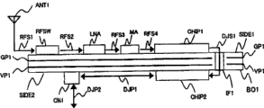
In the present embodiment, on the surface of substrate and these two faces of the inside, to high-density in the situation of installing component,, not only separate installed surface, and the allocation position on each installed surface is worked hard in order further to improve receiving sensitivity.As depicted in figs. 1 and 2, in the present embodiment, take to make the part of handling the faint high-frequency wireless signals of level in the such high-frequency circuit of input, amplifier LNA, HF switch RFSW and antenna ANT1 at the RF chip as far as possible away from the migration between " 0 "/" 1 " continually of the digital signal in the digital circuit, the configuration of the circuit that the noise generating capacity is big.Fig. 9 is the figure that understands this structure of ground explanation easily.
As shown in Figure 9, will be input to HF switch RFSW by the faint high-frequency wireless signals RFS1 that antenna ANT1 receives.In HF switch RFSW, select, will be input to amplifier LNA, it is amplified with predetermined magnification ratio through the high-frequency wireless signals RFS2 of decay somewhat.To import match circuit MA through the high-frequency wireless signals RFS3 that amplifies, will be input to RF chip CHIP1 through the high-frequency wireless signals RFS4 of impedance matching.In RF chip CHIP1, high-frequency wireless signals RFS4 is demodulated into digital signal DJS1, through interface IF1 it is taken into processor chips CHIP2.
In being called the such Wireless Telecom Equipment of WLAN, generally be used for the connector that communicates with digital signal, be used for and personal computer body exchange digital signal, in connector, exchange that high frequency ground moves between " 0 "/" 1 ", i.e. Gao Su digital signal.Therefore, exist the example that makes connector leave antenna at a distance.Relative therewith, in the sensor node SN1 of present embodiment, be that external sensor is connected with connector CN1, the signal DJP1 that exchanges between connector CN1 and processor chips CHIP2 moves very slow aerial signal, or than the digital signal of the clock signal low speed of processor chips CHIP2.Therefore, in the present embodiment connector CN1 is configured near the position the signal path of antenna ANT1~RF chip CHIP1, processor chips CHIP2 is configured on the signal path that the leaves antenna ANT1~RF chip CHIP1 position far away.If change performance, then so that the distance of connector CN1 and RF chip CHIP1 disposes connector CN1 than the mode of processor chips CHIP2 and the distance of RF chip CHIP1.Like this, component configuration shown in Figure 9 is the distinctive signal flow of capture sensor node well, becomes the component configuration that can realize compact in size simultaneously and improve receiving sensitivity.
(2) power supply is blocked in the power line of switch (please refer to Fig. 1,2,8) insertion high frequency low noise amplifier LNA the current sinking when suppressing standby.Generally, high frequency low noise amplifier LNA current sinking is big, even if also consume the electric current of about 10 μ A when standby.This current value is too big value for the sensor node that the restriction owing to size and purposes can not obtain sufficient power supply.But also exist the situation that does not have amplifier LNA can not reach the communication distance of practicality.
Therefore, as shown in Figure 8, power supply is blocked in the power line of switch P S20 insertion amplifier LNA the current sinking when subduing standby owing to this PS20.This power supply blocks switch, shown in Figure 10 (a)~(e), can use (a) to constitute by P-MOSFET MP1, (b) constitute by PNP bipolar transistor BP1, (c) constitute by N-MOSFET MN1, (d) constitute by npn bipolar transistor BN1, (e) intactly utilize the kind type of the output etc. of programmable imput output circuit PIO.In the whichever type, if control terminal SC1~5 that will drive from the lead-out terminal of the programmable imput output circuit PIO of processor chips CHIP2 are set on " 1 " or " 0 ", the power supply that then can be truncated to LNA is supplied with.In fact, although also flow through some leakage currents when switch element MP1~BN1 disconnects, Directory Value has the following magnitude of 0.1 μ A, and the leakage current in the time of can thinking this disconnection is to almost not influence of battery life.
On the other hand, during work, because the internal resistance of these switch elements MP1~BN1 is that some declines take place voltage.But, for example, the type of Figure 10 (a) etc., the internal resistance when switch element MP1 connects can be for 5 Ω about.As having stated, the current sinking in amplifier LNA when work is about 10mA, and the voltage that is caused by switch element MP1 descends and is about 50mV (=5 Ω * 10mA), be a negligible value.In addition, shown in Fig. 1 (e), when the output driving force of the programmable imput output circuit PIO of processor chips CHIP2 is very abundant, promptly during the current value more than the current value that in the time can fully supplying with work, needs, there is not the switch element shown in Figure 10 (a)~(d), power supply that yet can driving amplifier LNA.
So in the present embodiment, when not using amplifier LNA (beyond during reception), make power supply block switch P S20 and move to the state of blocking, when using amplifier LNA (during reception), make power supply block switch P S20 and move to conducting state.In fact, even if make power supply block switch from blocking state transition to conducting state, the internal circuit that also needs to wait for amplifier LNA reaches stable, typically needs about 1ms.But, the stand-by period of general sensor node SN1 and operating time relatively are very long, because relevant, suppose that operating time integral body is about about 1%, so can ignore the increase part of the consumed power that causes by the switching stand-by period to accepting state with situation.
(3) power supply is blocked in the power line of switch (please refer to Fig. 2) insertion transducer (built-in and attached) current sinking in the time that standby can being suppressed outward.We can say the current sinking when will the principle identical being applied to cut down the transducer standby with the 2nd feature of present embodiment.For example, as shown in Figure 2, the power line VDD2 of built-in temperature sensor TS1 can block switch P S1 by power supply and block power supply when the serviceability temperature transducer TS1 not.Now, developed the type (current sinking is about 5 μ A) of low consumpting power,, also can fully supply with the required electric current of work even if block the such type of switch P S1 Figure 10 (e) as power supply about temperature sensor.The type of Figure 10 (e) does not need to append discrete component, and adding cost ground is not realized.
In order to cut down the consumed power of outer attached transducer, also block the power line VDD3 (please refer to Fig. 2) that switch P S2 blocks the connector CN1 that connects outer attached transducer by power supply again.Generally, the consumed power of outer attached transducer when standby and when work all big than built-in temperature sensor.For example, need the current sinking of 1mA in acceleration transducer, again, the situation of not transferring to the function of holding state in the attached outside transducer self is a lot.Therefore, as present embodiment,, then be merely able to obtain about 1 week (8.3 days=200mAh/1mA/24h) working life with button cell expection if do not use power supply to block switch.Further take place when heavy-current discharge in the situation of battery capacity deterioration phenomenon, expection has only a few days at most.Relative therewith, by block only supply power in use of switch with power supply, when not using, block power supply, can improve battery life by leaps and bounds.
In the situation that attached transducer breaks down in short-circuit mode for a certain reason outside this being formed in also is effective.That is, outside outer attached transducer breaks down and do not block during the power supply of attached transducer, flow out big electric current from battery in instantaneous in short-circuit mode, battery is used up.But the power supply that has outer attached transducer in the present embodiment is in off-state usually, just drops into the such formation of power supply when just thinking to use transducer.Further, because by constituting the switch element supply power that power supply blocks switch, so also can be by the connection resistance of switch element electric current during with short circuit be suppressed to very low, and, by flowing through big electric current owing to short circuit, generation is descended by the voltage that inside battery resistance causes, can not guarantee that power supply blocks switch and returns automatically to off-state in order to make switch element keep connecting required bias voltage.
In the meantime, the output valve of attached transducer outside processor chips CHIP2 reads in through built-in AD translation circuit ADC, but because be in short-circuit condition, so can only read near the still exceptional value " 0 " current potential.Therefore, if give to give the such function of Control Software of carrying in processor chips, then can be absorbed in this situation of bad work from the outer attached transducer of this sensor node of external detection with being judged as unusual abnormal signal wireless transmission in this case.Further, in detecting the system of abnormal signal, also can to this sensor node send interrupt to use outside the control command of attached transducer, continue the work of sensor node in the mode of the outer attached transducer that do not use the generation problem.Further, as described later, if the id number from the memory circuitry MEM1 that is stored in processor chips CHIP2 can be isolated the sensor node that outer attached transducer breaks down, then also can processing and exchanging etc.
Below, the battery capacity of the button cell that the current sinking when our detailed description is used to avoid by work causes worsens the Poewr control method (please refer to Figure 11) of phenomenon.Sensor node after node and starting (P100) are set, are implemented initial setting program (P110), and is transferred to standby program (P120) immediately.In the early stage among the setting program P110, be stored in the PDATA file of running parameter in the non-volatile memories part in the memory circuitry MEM of processor chips CHIP2 etc. in advance according to storage, with the Working mode set of sensor node at desired state.In the PDATA file, for example storing transfer to operating state with several time intervals from holding state timer at interval, the frequency band of the transfer rate of radio communication, use and the information of intrinsic number assignment being given the id number etc. of each sensor node.Further, in mode of operation decision procedure described later (P200), used.Also the current sinking value with amplifier LNA, RF chip CHIP1, processor chips CHIP2, outer attached transducer etc. is stored in the PDATA file.In addition, among the setting program P110, processor chips CHIP2 works in the low consumpting power pattern in the early stage, also the clock X1 of the master clock X2 of disconnection process device chip CHIP2 and RF chip CHIP1.Again, the power supply that also is truncated to transducer and amplifier LNA is supplied with.
In standby program P120, have only the timing generative circuit TIM in the processor chips CHIP2 in running order, with working portion inhibition zone Min..By setting in this wise, the operating current in the time of can making standby typically can be cut to below the 5 μ A for number μ A.In addition, when the timer that takes place in the timer interval of setting inserts, transfer to following CPU starting sequence (P130) in occurring in initial setting program P110.If the insertion line of processor chips is connected with connector CN1 (Fig. 2),, also the start sensor node can connected under the requirement then by insertion from the outside again.
By CPU starting sequence P130, the master clock X2 of processor chips CHIP2 is connected, the processor circuit CPU in the starting CHIP2.After the starting, transfer to mode of operation determination procedure (P200).
In mode of operation determination procedure P200, by parameter/command analysis subprogram (P220),, read in the current sinking of each device from the PDATA file that has illustrated.At this moment, also can read in the order that receives that sends over from the external wireless terminal, for example launch requirements of sensing data etc.Order for example, is " the cranking temperature transducer is launched its result ".Parameter that following basis is read in and order are inferred in the subprogram (P230) at current sinking, infer and implement required current sinking.In timetable subprogram (P210), except satisfying requirement,, continue the start mode that decision read routine (P300) and data transmission receive program (P400) below so that the peak value of current sinking becomes minimum mode from the base station.
For example, in read routine P300, the current sinking when starting to work is about several mA, receives the required current sinking of data (10mA~when 20mA) comparing the external sensor that can not ignore, do not start data transmission simultaneously and receive program P400 with emission.Shown in Figure 12 is the waveform of the typical current sinking of sensor node at this moment.On the other hand, be built-in temperature sensor etc. at the transducer of starting, be only to consume in the situation of transducer of approximate number μ A electric current, start data transmission simultaneously and receive program P400.Shown in Figure 13 is and the typical current sinking waveform of this situation corresponding sensor node.By this power control, can reduce the peak value of current sinking.
The work of read routine P300 is as follows.At first, externally/built-in transducer judges and judges the classification of the transducer of starting in the subprogram (P310).Secondly by probe power promoter program (P320), if built-in transducer then is set at connection with PS1, if external sensor then is set at connection with PS2.Secondly, open in the subprogram (P330) at passage, for the sensor result of reading built-in or external sensor is opened required passage.For example, when reading shown in Figure 2 built-in temperature sensor TS1, the AD translation circuit ADC of start up process device chip CHIP2 is set in the state that can read in the input terminal I2 of ADC.Again, when the transducer of wanting to start is with connector CN1 shown in Figure 2 is connected external sensor, with the input terminal of the AD translation circuit ADC of correspondence, perhaps, the input and output terminal of programmable imput output circuit PIO is set in the desired mode of operation.So, be set in the state that can read from the data of transducer.And, read/write out in the subprogram (P340) at next sensing data, in fact, be stored among the file SDATA on the memory circuitry MEM by processor chips CHIP2 read sensor data.If desired sensing data is written out in the file SDATA with said sequence, then disconnect in the subprogram (P350) at next pathway closure/ADC, the AD translation circuit ADC and the programmable imput output circuit PIO that use are transferred to holding state, finish read routine P300.
Below, we illustrate that data transmission receives the work of program P400.At first the 1st, connect in the subprogram (P410) at clock X1, the clock X1 of RF chip CHIP1 is begun, starting RF chip CHIP1.At this moment, be to carry out with the form of RF chip regulation by processor chips CHIP2 starting RF chip CHIP1 through the control signal wire CS that has illustrated.Secondly judge subprogram (P420), which work in judging whether to launch or to receive by emission reception work.In this program, for example, at first from sensor node to the base station sensing data, after this sensor node is transferred to accepting state.Sensor node is standby in accepting state, till the affirmation improving backhaul that the base station is not received mistakenly the sensing data of emission from the base station is come.Implement above sequential control by subprogram P420.Below, we transmit and receive work at explanation.
When emission work, by subprogram P430, RFSW switches to emission state with HF switch.Through control signal wire CS the messaging parameter of the transfer rate used and frequency band etc. is sent to RF chip CHIP1 again.Then, by subprogram P440, the file SDATA pickup data on the memory MEM send to RF chip CHIP1 through data signal line DS, by radio communication sensing data are transmitted into the outside.
When receiving work, by subprogram P450, set the messaging parameter of HF switch RFSW and RF chip CHIP1, and the LNA power supply is blocked switch P S20 be set in conducting state, further, make the start terminal activate of LNA.Then, receive data, be written in the PDATA when needing by subprogram P460.
In addition, omit in order to simplify in the above description, but in fact, because the switching of the starting of amplifier LNA and HF switch RFSW, further, the starting of the clock X1 of RF chip CHIP1 respectively need be up to the stable time (typically, several 100 μ s~number ms), so need only suitable with this time etc. pending in each program.Equally, the clock of the dump of amplifier LNA and RF chip CHIP1 cuts off also need need the stand-by period to handle up to the stable time.
At last, if reception then in subprogram P470, stops clock X1 from the confirmation of receipt signal of base station, make RF chip CHIP1 get back to off-state.Further, in subprogram P140, stop the master clock X2 of processor chips CHIP2, transfer to standby program P120.
Like this, judge the current sinking that needs in the present embodiment, the mode that selection does not make the current capacity of button cell worsen in advance.That is, when transducer consumes the current sinking of number mA, start data transmission simultaneously and receive and transducer, will give button cell and make the deep heavy load that worsens of its battery capacity probably.Shown in Figure 14 is the waveform example of the current sinking in this situation.With the situation of application control mode of the present invention shown in Figure 12 relatively peak current (Ip3) become sizable value (Ip3〉Ip1).On the other hand, if relatively Figure 12 and Figure 14 then can see, in the control mode of Figure 12, because receive, so in order to finish the required time lengthening of a series of processing (Ttotal1〉Ttotal3) in the emission of the laggard line data of start sensor.Again, average consumed cur-rent, the situation of Figure 12 want somewhat big.But when as the power supply of sensor node SN1 during with the button cell of CR2032 etc., the current sinking that can use in the scope that battery capacity is worsened mostly is the 0.1mA magnitude most.On the other hand, the electric current of the need of work 10mA magnitude of sensor node.But, exist and make when using button cell that battery life is extreme to worsen such problem with this current value.For fear of this problem, in the scope of our checking, the peak value that suppresses current sinking is the most effective.That is, in order to realize long-life work in the sensor node of button cell work, the peak value of current sinking need be suppressed to alap value, this is absolutely necessary.Therefore, even if what increase average consumed cur-rent, consider that the control mode of present embodiment of the characteristic of button cell stably carries out work with button cell in also can be between long-term.
On the other hand, when the current sinking of transducer is about several μ A, make working sensor simultaneously, also change the peak value of current sinking hardly even if receive with the emission of data.That is, when start sensor, one side reads out the data one side emission sensor data from this transducer, can save the time that spends in a succession of operation.That is, because transfer to holding state in the short time, this can suppress battery consumption.
According to above such Poewr control method, can consider the work of the characteristic of button cell, the result can realize long-life work when button cell is worked.
Figure 15 represents to be made of 3 substrates the example of sensor node.Sensor node is by this structure base board BO1, and power supply board BO2 and Control Software write substrate BO3 and constitute.When common use, with the use that combines of this structure base board BO1 and power supply board BO2.When rewriting Control Software etc., this structure base board BO1 and Control Software are write the substrate BO3 use that combines again.Wherein, because the formation of this structure base board BO1 is identical with the sensor node SN1 that has illustrated, so we omit the detailed description to it.
Power supply board BO2 by the connector CN2 that is connected with this structure base board BO1, the sensor special passage SP1 that connects outer attached transducer, the power supply that blocks the power supply of sensor passage SP1 block switch P S21, power-on reset circuit POR1, manually reset switch SW2, external power supply connector PP1, power selection switch SW1, button cell BAT1, adjuster REG1 constitute.Power supply board BO2 will be from this structure base board of power supply BO1 of built-in button cell through connector CN2.Again, will be used for being configured in sensor passage SP1 from the holding wire of this structure base board BO1 pickup, can connect outer attached transducer through CN2.
Equally, Control Software write substrate BO3 by the connector CN3 that is connected with this structure base board BO1, the sensor special passage SP2 that connects outer attached transducer, the power supply that blocks the power supply of sensor passage SP2 block switch P S21, power-on reset circuit POR2, manually reset switch SW3, external power supply connector PP1, adjuster REG2 and the program rewriting passage DPB that carries on processor chips constitute.Substrate BO3 obtains power from the external power source that is connected with external power supply connector PP1, supplies with the required power of this structure base board BO1 work.Further, through program rewriting terminal DPB, rewrite the Control Software of carrying on the processor chips of this structure base board BO1.Signal line passes connector CN3, the CN1 of this program rewriting terminal are connected with the program rewriting terminal of processor chips, rewrite the Control Software of carrying through this terminal.
As described above, sensor node assigned on each substrate constitute, have following advantage.That is can unwanted program rewriting terminal not carried on this structure base board BO1 when, using usually yet.Therefore, can reduce the size of this structure base board.On the other hand, when affirmation/adjustment software work, be difficult to handle undersized sensor node on the contrary.By the such formation of Figure 15, also can rewrite to draw on the substrate and adjust required holding wire etc. in the unquestioned Control Software of size.That is, can cut down and spend in the time of adjusting in the operation, can significantly shorten the time that spends in the exploitation.
The sensor node of the present invention that is to use shown in Figure 16 is constructed the example of sensor network system.In Figure 16, SN1~SN6 is a sensor node of the present invention, for example, in order to control the air-conditioning of whole building, is dispersed in the whole building.The sensor node of these distributions carries out radio communication by radio communication with base station BS 1, sends the temperature data of reading.Base station BS 1 is made of antenna ANT1, wireless communication interface RF1, processor CPU1, memory MEM 1, secondary storage device STR1, display unit DISP1, user's interface device UI1 and network interface NI1.Wherein, secondary storage device STR1 typically, is made of hard disk etc.Again, display unit DISP1 is made of CRT etc., and user's interface device UI1 is made of keyboard/mouse etc.In Figure 17, represented in native system, to be transmitted to the data configuration of the sensing data of base station from sensor node.Base station BS 1 carries out radio communication through wave point/antenna with sensor node, reads the determination data of temperature etc.In base station BS 1, according to receiving determination data, the quality judging program QPR1 according to being stored on secondary storage device STR1 or the memory MEM 1 controls the temperature of whole building.Further, through network interface NI1,, can communicate with remote management server SV10 by being the wide area network network diagram WAN1 of representative with internet etc.
The sensor node of the application of the invention, at first, because receiving sensitivity is good, so, also can positively communicate with the base station even if the base station is positioned at a distance.That is,, import the required cost of sensor node system so can cut down significantly because can cut down the quantity of base station.Further, sensor node of the present invention because battery life is very long, can no problemly not carry out work continuously so do not need to change continually battery.That is, can cut down the maintenance cost in the sensor node system integral body significantly, can construct sensor node system with low cost with the function of wanting.
Therefore the sensor node that can provide according to the present invention can high sensitivity, low power consumption carries out work, can construct the sensor node system in the various different field.
Claims (7)
1. electronic installation comprises:
Connector is used to connect transducer;
The 1st signal processing circuit receives the sensing data of importing via above-mentioned connector from the sensor, forms according to the sensor data and sends data;
The 2nd signal processing circuit will become high-frequency signal from the above-mentioned transmission data conversion of above-mentioned the 1st signal processing circuit;
Imput output circuit receives the input of above-mentioned high-frequency signal, via antenna it is exported; With
Substrate has first and above-mentioned the 2nd signal processing circuit of installation and above-mentioned imput output circuit second that above-mentioned connector and above-mentioned the 1st signal processing circuit are installed,
Wherein, above-mentioned first and above-mentioned second face become the surface and the back side of aforesaid substrate, so that the signal path between above-mentioned the 1st signal processing circuit and above-mentioned the 2nd signal processing circuit turns back.
2. electronic installation according to claim 1, wherein:
On aforesaid substrate, be provided with and be suppressed at the screen that the noise that produces in above-mentioned the 1st signal processing circuit is sent to above-mentioned the 2nd signal processing circuit.
3. electronic installation according to claim 2, wherein:
As above-mentioned screen, the 1st plane layer that is given the 1st current potential and the 2nd plane layer that is given the 2nd current potential are set,
Above-mentioned the 1st current potential is the reference potential of above-mentioned the 1st signal processing circuit, and above-mentioned the 2nd current potential is the power supply potential of above-mentioned the 1st signal processing circuit.
4. electronic installation according to claim 3, wherein:
Form above-mentioned the 1st plane layer as than above-mentioned the 2nd plane layer more near the 2nd layer of aforesaid substrate.
5. electronic installation according to claim 2, wherein:
Above-mentioned screen is arranged on the inside of aforesaid substrate.
6. electronic installation according to claim 1, wherein:
Via above-mentioned connector power supply is offered the sensor,
Above-mentioned the 1st signal processing circuit is intermittently moved the sensor, when the sensor is failure to actuate, cuts off the power supply of the sensor is supplied with.
7. electronic installation according to claim 1 comprises:
Be built in the built-in sensors of above-mentioned electronic installation,
Above-mentioned the 1st signal processing circuit is intermittently moved above-mentioned built-in sensors, when above-mentioned built-in sensors is failure to actuate, cuts off the power supply of above-mentioned built-in sensors is supplied with.
Applications Claiming Priority (2)
| Application Number | Priority Date | Filing Date | Title |
|---|---|---|---|
| JP2004064973A JP4049112B2 (en) | 2004-03-09 | 2004-03-09 | Electronic equipment |
| JP2004064973 | 2004-03-09 |
Related Child Applications (1)
| Application Number | Title | Priority Date | Filing Date |
|---|---|---|---|
| CN2008100876640A Division CN101257768B (en) | 2004-03-09 | 2004-09-01 | Electronic circuit and its control method |
Publications (2)
| Publication Number | Publication Date |
|---|---|
| CN1667975A CN1667975A (en) | 2005-09-14 |
| CN100533997C true CN100533997C (en) | 2009-08-26 |
Family
ID=34918211
Family Applications (2)
| Application Number | Title | Priority Date | Filing Date |
|---|---|---|---|
| CN2008100876640A Expired - Fee Related CN101257768B (en) | 2004-03-09 | 2004-09-01 | Electronic circuit and its control method |
| CNB2004100749810A Expired - Fee Related CN100533997C (en) | 2004-03-09 | 2004-09-01 | Electronic circuit and control method therefor |
Family Applications Before (1)
| Application Number | Title | Priority Date | Filing Date |
|---|---|---|---|
| CN2008100876640A Expired - Fee Related CN101257768B (en) | 2004-03-09 | 2004-09-01 | Electronic circuit and its control method |
Country Status (3)
| Country | Link |
|---|---|
| US (2) | US7304857B2 (en) |
| JP (1) | JP4049112B2 (en) |
| CN (2) | CN101257768B (en) |
Families Citing this family (25)
| Publication number | Priority date | Publication date | Assignee | Title |
|---|---|---|---|---|
| DE102004008738A1 (en) * | 2004-02-23 | 2005-09-08 | BSH Bosch und Siemens Hausgeräte GmbH | Electronic assembly and method of making this |
| JP4552670B2 (en) * | 2005-01-31 | 2010-09-29 | 株式会社日立製作所 | Sensor node, base station, and sensor network system |
| JP4848732B2 (en) * | 2005-10-17 | 2011-12-28 | 株式会社日立製作所 | Terminal device |
| US8290747B2 (en) * | 2005-10-21 | 2012-10-16 | Microstrain, Inc. | Structural damage detection and analysis system |
| JP4800981B2 (en) * | 2006-02-08 | 2011-10-26 | セイコーインスツル株式会社 | Wireless communication device |
| JP5285842B2 (en) * | 2006-04-13 | 2013-09-11 | パナソニック株式会社 | Integrated circuit mounting board and power line communication device |
| US8118483B2 (en) * | 2006-06-21 | 2012-02-21 | Intel Corporation | Thermal sensor having toggle control |
| JP4814018B2 (en) | 2006-08-29 | 2011-11-09 | 株式会社日立製作所 | Sensor node |
| US20080225445A1 (en) * | 2007-03-14 | 2008-09-18 | Zippy Technology Corp. | Arc-discharge protection device with temperature detection mode |
| US8115629B2 (en) * | 2009-09-24 | 2012-02-14 | Microdata Corporation | Collective objects management system using R.F. object identification with multiple crystals |
| KR101049477B1 (en) | 2009-09-30 | 2011-07-15 | 제주대학교 산학협력단 | Sensor interface board assembly |
| JP5470556B2 (en) * | 2010-07-16 | 2014-04-16 | 伊原電子工業株式会社 | Biological signal detection device, control method thereof, and program |
| JP5269864B2 (en) * | 2010-12-07 | 2013-08-21 | 株式会社東芝 | Semiconductor device |
| US9258030B2 (en) | 2011-02-10 | 2016-02-09 | Mediatek Inc. | Wireless communication device |
| US9713093B2 (en) | 2011-02-10 | 2017-07-18 | Mediatek Inc. | Wireless communication device |
| US9369172B2 (en) | 2011-02-10 | 2016-06-14 | Mediatek Inc. | Wireless communication device |
| US8971378B2 (en) | 2011-02-10 | 2015-03-03 | Mediatek Inc. | Wireless communication device |
| JP5818310B2 (en) * | 2011-06-27 | 2015-11-18 | セイコーインスツル株式会社 | Sensor terminal, sensor system and method thereof |
| US20130039230A1 (en) * | 2011-08-09 | 2013-02-14 | Jaesik Lee | Method and Device for Wireless Broadcast Power-up Sequence in Wireless Sensor Network |
| CN104583897B (en) * | 2012-07-24 | 2017-12-26 | 瑞萨电子株式会社 | Semiconductor devices and electronic equipment |
| JP6340285B2 (en) | 2014-08-22 | 2018-06-06 | ルネサスエレクトロニクス株式会社 | Semiconductor device, electronic device and sensing method |
| JP6571358B2 (en) * | 2015-03-24 | 2019-09-04 | 三菱重工サーマルシステムズ株式会社 | Circuit board for power conversion and electric compressor |
| KR20160120496A (en) * | 2015-04-08 | 2016-10-18 | 삼성전기주식회사 | Mounting module |
| WO2018168500A1 (en) * | 2017-03-15 | 2018-09-20 | 株式会社村田製作所 | High frequency module and communication device |
| US11375607B2 (en) * | 2019-03-28 | 2022-06-28 | Apple Inc. | Mirrored voltage regulator for high-current applications and method the same |
Citations (4)
| Publication number | Priority date | Publication date | Assignee | Title |
|---|---|---|---|---|
| US5938956A (en) * | 1996-09-10 | 1999-08-17 | Micron Technology, Inc. | Circuit and method for heating an adhesive to package or rework a semiconductor die |
| US6064116A (en) * | 1997-06-06 | 2000-05-16 | Micron Technology, Inc. | Device for electrically or thermally coupling to the backsides of integrated circuit dice in chip-on-board applications |
| US6567703B1 (en) * | 2000-11-08 | 2003-05-20 | Medtronic, Inc. | Implantable medical device incorporating miniaturized circuit module |
| CN1461057A (en) * | 2002-05-23 | 2003-12-10 | 罗姆股份有限公司 | Image sensor assembly and its mfg. method |
Family Cites Families (26)
| Publication number | Priority date | Publication date | Assignee | Title |
|---|---|---|---|---|
| US4517535A (en) * | 1982-07-28 | 1985-05-14 | Dalmo Victor Operations, Bell Aerospace Textron, Div. Of Textron, Inc. | High speed high power step attenuator method and apparatus |
| US4616655A (en) * | 1984-01-20 | 1986-10-14 | Cordis Corporation | Implantable pulse generator having a single printed circuit board and a chip carrier |
| US5144548A (en) * | 1988-07-15 | 1992-09-01 | Iris Technologies, Inc. | Routing switcher |
| US5535274A (en) * | 1991-10-19 | 1996-07-09 | Cellport Labs, Inc. | Universal connection for cellular telephone interface |
| JPH1027987A (en) * | 1996-07-10 | 1998-01-27 | Hitachi Ltd | Low emi circuit board and low emi cable connector |
| US5781078A (en) * | 1996-12-05 | 1998-07-14 | Glenayre Electronics, Inc. | Filter enhancement using input-to-output ground isolation and shielding |
| KR100238408B1 (en) * | 1997-02-26 | 2000-01-15 | 김승찬 | Anti-theft system for computer |
| US6010257A (en) * | 1997-03-18 | 2000-01-04 | Comtec Information Systems Inc. | Miniature portable interactive printer |
| JPH117596A (en) | 1997-06-18 | 1999-01-12 | Penta Ocean Constr Co Ltd | Data detecting device and its power source managing method |
| WO1999013676A2 (en) * | 1997-09-12 | 1999-03-18 | Williams Wireless, Inc. | Wide area telemetry network |
| US6013876A (en) * | 1998-01-23 | 2000-01-11 | General Instrument Corporation | Method and device for electrically connecting circuits to opposite surfaces of a printed circuit board |
| JP3199039B2 (en) * | 1998-11-02 | 2001-08-13 | 日本電気株式会社 | Power consumption reduction circuit, wireless communication device using the same, and power consumption reduction method in wireless communication device |
| JP2001127652A (en) | 1999-10-22 | 2001-05-11 | Matsushita Electric Ind Co Ltd | High frequency radio |
| JP2001213008A (en) | 2000-02-03 | 2001-08-07 | Casio Comput Co Ltd | Gray scale print controller |
| JP2001232843A (en) | 2000-02-23 | 2001-08-28 | Alps Electric Co Ltd | Thermal printer and method of recording therefor |
| JP2001337931A (en) | 2000-05-29 | 2001-12-07 | Matsushita Electric Ind Co Ltd | Portable terminal device |
| US6487082B1 (en) * | 2000-07-20 | 2002-11-26 | Silicon Graphics, Inc. | Printed circuit board component packaging |
| JP4338885B2 (en) | 2000-08-22 | 2009-10-07 | パナソニック株式会社 | Mobile terminal device having wireless communication function and response method thereof |
| JP3642029B2 (en) | 2001-02-06 | 2005-04-27 | 日本電気株式会社 | Mobile phone |
| JP4274453B2 (en) | 2001-07-02 | 2009-06-10 | 横浜ゴム株式会社 | Vehicle tire monitoring system |
| US6672174B2 (en) * | 2001-07-23 | 2004-01-06 | Fidelica Microsystems, Inc. | Fingerprint image capture device with a passive sensor array |
| JP2003078279A (en) * | 2001-09-04 | 2003-03-14 | Konica Corp | Shielding method of printed board and device mounting printed board using that method |
| US8004854B2 (en) * | 2002-01-24 | 2011-08-23 | Adc Dsl Systems, Inc. | Electrical noise protection |
| JP2003234657A (en) | 2002-02-08 | 2003-08-22 | Sanyo Electric Co Ltd | Radio equipment |
| US6924496B2 (en) * | 2002-05-31 | 2005-08-02 | Fujitsu Limited | Fingerprint sensor and interconnect |
| US6903910B1 (en) * | 2004-08-06 | 2005-06-07 | Azijuth Networks, Inc. | Shielded enclosure with user-installable interface modules |
-
2004
- 2004-03-09 JP JP2004064973A patent/JP4049112B2/en not_active Expired - Fee Related
- 2004-09-01 CN CN2008100876640A patent/CN101257768B/en not_active Expired - Fee Related
- 2004-09-01 CN CNB2004100749810A patent/CN100533997C/en not_active Expired - Fee Related
- 2004-09-03 US US10/933,270 patent/US7304857B2/en not_active Expired - Fee Related
-
2007
- 2007-10-19 US US11/976,041 patent/US7663893B2/en not_active Expired - Fee Related
Patent Citations (4)
| Publication number | Priority date | Publication date | Assignee | Title |
|---|---|---|---|---|
| US5938956A (en) * | 1996-09-10 | 1999-08-17 | Micron Technology, Inc. | Circuit and method for heating an adhesive to package or rework a semiconductor die |
| US6064116A (en) * | 1997-06-06 | 2000-05-16 | Micron Technology, Inc. | Device for electrically or thermally coupling to the backsides of integrated circuit dice in chip-on-board applications |
| US6567703B1 (en) * | 2000-11-08 | 2003-05-20 | Medtronic, Inc. | Implantable medical device incorporating miniaturized circuit module |
| CN1461057A (en) * | 2002-05-23 | 2003-12-10 | 罗姆股份有限公司 | Image sensor assembly and its mfg. method |
Also Published As
| Publication number | Publication date |
|---|---|
| JP2005260291A (en) | 2005-09-22 |
| US20050200002A1 (en) | 2005-09-15 |
| US20080130253A1 (en) | 2008-06-05 |
| US7663893B2 (en) | 2010-02-16 |
| CN101257768A (en) | 2008-09-03 |
| US7304857B2 (en) | 2007-12-04 |
| CN101257768B (en) | 2012-02-22 |
| CN1667975A (en) | 2005-09-14 |
| JP4049112B2 (en) | 2008-02-20 |
Similar Documents
| Publication | Publication Date | Title |
|---|---|---|
| CN100533997C (en) | Electronic circuit and control method therefor | |
| US7593752B2 (en) | Sensor node, base station, and sensor network system | |
| TWI249709B (en) | Distributed RF coupled system | |
| JP5751384B2 (en) | Wireless communication device | |
| EP2928015B1 (en) | Radio frequency ic device and electronic apparatus | |
| US7321753B2 (en) | Wireless transmission circuit enabling modulation of radio frequency power amplification | |
| JP3651553B2 (en) | Mobile information processing device | |
| JP2006295729A (en) | Rfid tag and antenna arrangement method | |
| JP2006262055A (en) | Antenna module and portable information terminal provided with the same | |
| JP4301254B2 (en) | Electronic device and sensor network system | |
| KR101086856B1 (en) | Semiconductor Integrated Circuit Module and PCB Apparatus with the Same | |
| US11184053B2 (en) | Communication device and communication method | |
| JP2009153208A (en) | Electronic circuit and control method thereof | |
| US9820374B2 (en) | Use of hybrid PCB materials in printed circuit boards | |
| JP2009010994A (en) | Electronic circuit and its control method | |
| JP4985732B2 (en) | IC tag reading / writing device, electronic device, and IC tag reading / writing method | |
| JP2008289131A (en) | Transmitting device and electronic apparatus using the same | |
| US7327035B2 (en) | System and method for providing a low frequency filter pole | |
| CN215529012U (en) | Wireless communication circuit based on CC1101 chip | |
| JP4273995B2 (en) | Wireless circuit of home electrical equipment network control information terminal equipment | |
| US20230395973A1 (en) | Antenna switching circuitry set and electronic device | |
| US20230030534A1 (en) | Guard trace ground via optimization for high-speed signaling | |
| JP2000223931A (en) | Antenna device, electronic device provided with the same and electronic equipment | |
| CN109273825A (en) | Electronic equipment | |
| WO2002084893A1 (en) | Data processing terminal, terminal designing device and method, computer program, information storing medium |
Legal Events
| Date | Code | Title | Description |
|---|---|---|---|
| C06 | Publication | ||
| PB01 | Publication | ||
| C10 | Entry into substantive examination | ||
| SE01 | Entry into force of request for substantive examination | ||
| C14 | Grant of patent or utility model | ||
| GR01 | Patent grant | ||
| C17 | Cessation of patent right | ||
| CF01 | Termination of patent right due to non-payment of annual fee |
Granted publication date: 20090826 Termination date: 20130901 |