CN100555898C - The method and apparatus of in communication system, dynamically avoiding shared channel to disturb - Google Patents
The method and apparatus of in communication system, dynamically avoiding shared channel to disturb Download PDFInfo
- Publication number
- CN100555898C CN100555898C CN01823822.XA CN01823822A CN100555898C CN 100555898 C CN100555898 C CN 100555898C CN 01823822 A CN01823822 A CN 01823822A CN 100555898 C CN100555898 C CN 100555898C
- Authority
- CN
- China
- Prior art keywords
- medium
- control signal
- modulator
- transmission
- demodulator
- Prior art date
- Legal status (The legal status is an assumption and is not a legal conclusion. Google has not performed a legal analysis and makes no representation as to the accuracy of the status listed.)
- Expired - Fee Related
Links
Images


Classifications
-
- H—ELECTRICITY
- H04—ELECTRIC COMMUNICATION TECHNIQUE
- H04L—TRANSMISSION OF DIGITAL INFORMATION, e.g. TELEGRAPHIC COMMUNICATION
- H04L5/00—Arrangements affording multiple use of the transmission path
- H04L5/02—Channels characterised by the type of signal
- H04L5/06—Channels characterised by the type of signal the signals being represented by different frequencies
-
- H—ELECTRICITY
- H04—ELECTRIC COMMUNICATION TECHNIQUE
- H04B—TRANSMISSION
- H04B3/00—Line transmission systems
- H04B3/02—Details
- H04B3/46—Monitoring; Testing
- H04B3/487—Testing crosstalk effects
-
- H—ELECTRICITY
- H04—ELECTRIC COMMUNICATION TECHNIQUE
- H04L—TRANSMISSION OF DIGITAL INFORMATION, e.g. TELEGRAPHIC COMMUNICATION
- H04L5/00—Arrangements affording multiple use of the transmission path
- H04L5/14—Two-way operation using the same type of signal, i.e. duplex
- H04L5/143—Two-way operation using the same type of signal, i.e. duplex for modulated signals
Abstract
The present invention relates in communication system, to be used between transmission medium CH-X, the CH-Y of the uplink and downlink communication that is used for frequency spectrum, producing after the crosstalk method of dynamic assignment communication system frequency spectrum and closed equipment.Described method comprises the steps:-is detecting by the crosstalk CTI that transmission caused that produces on the transmission medium CH-Y that disturbs on the transmission medium CH-X that is disturbed.-medium control signal CS of transmission on the transmission medium CH-X that is disturbed.-producing the detection reproducing medium control signal CS ' reproduced on the transmission medium CH-Y that disturbs because of cross-talk.
Description
Technical field
The present invention relates to be used for the method and apparatus of dynamic assignment communication system frequency spectrum after producing interference between the transmission medium that uses frequency spectrum.
Background technology
Resource is handled and the resource use is the basis of any modern communications.Concerning Very-high-speed Digital Subscriber Line VDSL modulator-demodulator, this basic problem is represented by frequency planning.In VDSL, frequency planning must take in numerous aspects such as politics, economy and practices.Different frequency plannings is fit to the difference service that some operators support, practical problems has then been introduced a lot of subsidiary restrictions.The example of these practical problems aspects be used for the radio amateur the HAM frequency range the position and as the frequency planning of other broadband systems of ADSL (Asymmetric Digital Subscriber Line) (ADSL) and so on.Current, comprise that the modal system of VDSL has all used fixing spectrum allocation may.This will cause the underutilization of medium.
Signal transmission in the copper equipment can be subjected to cross-talk effects, this means the interference of the signal that the communication on the given line can be subjected to transmitting on the All other routes.Usually, the coupling meeting between circuit is along with frequency improves, but in fact described coupling also can the marked change with the circuit difference.Yet, enter the only just very strong usually of any given line from the cross-talk of a small amount of All other routes.
Modern digital subscribers feeder DSL system is designed to be subjected to the restriction of near-end crosstalk NEXT or far-end crosstalk FEXT.Concerning the system that is subjected to the FEXT restriction, promptly avoid NEXT in order to control cross-talk, be necessary to carry out frequency planning.The system that is subjected to the NEXT restriction is then without any need for spectrum management, but these systems still can benefit from transmit power management.In the system that is subjected to the FEXT restriction, usually the uplink and downlink traffic carrying capacity is assigned to different frequency ranges.If there is not this FDD, NEXT will greatly reduce the active volume in the network so.Similar to such multi-user interference, we can compare with the situation in the cellular radio communication system.Copper cash in the DSL system only can seriously disturb a small amount of adjacent lines, has played thus and the identical effect of directional antenna in the cellular system.Yet compare with FDD is only arranged, cellular radio system has complicated more resource allocation mechanism usually.Correspondingly, in copper equipment, lack efficient resource allocation mechanism, and this will cause the wretched insufficiency that utilizes of available resources.In U.S. Pat 6,167, a kind of method of distributing the uplink and downlink communication spectrum in variable mode is disclosed in 095.In this part United States Patent (USP), the uplink and downlink of frequency spectrum partly are to distribute according to the signal quality parameter of the expression line conditions that calculates.Before the frequency allocation in carrying out frequency spectrum, must characterize signal.Chaotic resource allocation might cause system crash.For fear of system crash, be necessary between modulator-demodulator, to coordinate.If there is not the present invention, so this coordination needs a central site (central site) of determining the uplink and downlink carrier frequency according to the circuit noise characteristic usually.
Summary of the invention
According to a kind of method that in communication system, is used for dynamic assignment communication system frequency spectrum after the crosstalk between the transmission medium of the uplink and downlink communication that is used for frequency spectrum of the present invention, said method comprising the steps of:
Detect the crosstalk owing to the coupling of the cross-talk between the medium on the transmission medium that is disturbed, wherein said crosstalk is to be caused by the transmission that produces the data on the transmission medium that disturbs, and described method is characterised in that following steps:
On the transmission medium that is disturbed, transmit a medium control signal as the result of the crosstalk of previous detection;
Producing the medium control signal that detects reproduction on the transmission medium that disturbs, the medium control signal of this reproduction is the reproduction owing to the medium control signal of cross-talk coupling.
According to a kind of equipment that in communication system, is used for dynamic assignment communication system frequency spectrum after the crosstalk between the transmission medium of the uplink and downlink communication that is used for frequency spectrum of the present invention, comprising:
Detect the device of crosstalk on the transmission medium that is disturbed, wherein said crosstalk is to be caused by the transmission that produces on the transmission medium that disturbs because of the cross-talk coupling between the medium, it is characterized in that:
Be used on the transmission medium that is disturbed, transmitting the device of a medium control signal as the result of the previous crosstalk that detects;
Be used at the device that produces the medium control signal that detection is reproduced on the transmission medium that disturbs, the medium control signal of this reproduction is the reproduction owing to the medium control signal of cross-talk coupling.
The invention solves those and relate to the problem of under the situation of not using the center Mediation Device, dynamically effectively distributing frequency spectrum.For making some medium notice possible disturbed condition, between medium, used the cross-talk coupling, solve this problem with this.The present invention has used such fact, if on first transmission medium that is disturbed, produced interference owing to produce the transmission cross-talk coupling of second transmission medium that disturbs, there is the cross-talk coupling so in the opposite direction equally, on this meaning, interference and cross-talk coupling are symmetrical.Because the symmetry of cross-talk coupling, the transmission meeting on first medium occurs as the interference on second medium by the cross-talk coupling.According to the present invention, after crosstalk, sent a medium control signal on the medium being disturbed.Then, described medium control signal will be reproduced and obtain detecting on the medium that produces interference.Default direction according to the rules or go up whether used relevant medium in the opposite direction with default side can be carried out different measurements.
In more detail, in first embodiment, crosstalk is to record on the employed transmission medium that is disturbed of modulator-demodulator pair set that is disturbed in communication system.In this system, can cause interference because of the cross-talk coupling by the transmission medium that produces the employed generation interference of the modulator-demodulator pair set that disturbs.The medium control signal then is to be sent on the medium that is disturbed by the modulator-demodulator pair set that is disturbed.Because cross-talk coupling, described medium control signal can be reproduced on the medium that produces interference and be detected by producing the modulator-demodulator pair set that disturbs.
In more detail, in a second embodiment, it is by transmitting in the frequency spectrum resource of receiving terminal modulator-demodulator on producing the transmission medium that disturbs that produces in the modulator-demodulator pair set that disturbs that data are avoided in conflict.It is to avoid occurring the conflict of strong NEXT interference mode that the purposes of data is avoided in conflict.Crosstalk then is to detect being disturbed on the employed transmission medium that is disturbed of modulator-demodulator pair set.Because the cross-talk coupling avoids data will cause interference in the conflict that produces on the medium that disturbs.The medium control signal is then by being disturbed the modulator-demodulator pair set to send being disturbed on the medium.Because cross-talk coupling, produce on the medium that disturbs will the reproducing medium control signal and described medium signal will record by producing the modulator-demodulator pair set that disturbs.
In more detail, the modulator-demodulator that is subjected to interference effect in the system is to being synchronous in time in the 3rd embodiment.Then, in the frequency spectrum that produces the transmission medium that disturbs, the receiving terminal modulator-demodulator in the modulator-demodulator pair set that so-called generation is disturbed sends conflict simultaneously and avoids data in predefined first group of time slot.Crosstalk is to detect on the transmission medium that is disturbed that is disturbed the modulator-demodulator pair set to use.Conflict from one of medium that produces interference avoids data to cause interference.The medium control signal is then being disturbed on the medium by being disturbed the modulator-demodulator pair set to send at predefined second group of time slot.Will reproduce described medium control signal and described medium control signal on the medium that produces interference is to record by producing the modulator-demodulator pair set that disturbs.
In more detail, another modulator-demodulator is right in the 4th embodiment, and just so-called noiseless modulator-demodulator is to detecting one second reproducing medium control signal.Described second control signal is from being disturbed the modulator-demodulator pair set to reproduce the above-mentioned medium control signal (referring to the embodiment of front) of being disturbed medium to send.In this embodiment, the medium control signal has comprised about the information of the transmission direction of the transmission medium that disturbed and because second cross-talk coupling and reproducing on noiseless medium.Because the transmission direction information that is transmitted, noiseless modulator-demodulator also can be measured selecting to ignore this signal, so that handle this situation.
If do not disturb other users, then the user in the system can dynamically take the capacity that they need, and on this meaning, the objective of the invention is to use the capacity in the network.
An advantage of the invention is and to come the flexible allocation capacity as required.
Another advantage then is not need the center Mediation Device.
Another advantage is to promote traffic loads under situation about not loosening the control of system in addition.For the total traffic load of appropriateness, its utilization to medium is planned much better than static frequency.By promoting traffic loads, performance will descend towards the direction of the performance of static frequency planning.
To come the present invention is made a more detailed description by those preferred embodiments that combines with attached drawings now.
Description of drawings
Figure 1A shows is the schematic block diagram that has comprised the right communication system of those modulator-demodulators with receiving terminal modulator-demodulator and transmitting terminal modulator-demodulator.
What Figure 1B showed is the frequency spectrum that is divided into one group of illustrative different frequency channel, and wherein each frequency channels all has the default direction of regulation.
What Fig. 2 showed is a schematic block diagram with modulator-demodulator of the interference of producing to the communication system right with being disturbed modulator-demodulator, and wherein each modulator-demodulator is to all having a receiving terminal modulator-demodulator and transmitting terminal modulator-demodulator.Side signal transmission among the figure to disclosed be signal transmission among first embodiment.
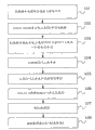
Fig. 3 has shown the flow chart that first embodiment when using a purpose signal is described.
Fig. 4 shows is the schematic block diagram with the right communication system of two modulator-demodulators.Side signal transmission among the figure to disclosed be signal transmission among second embodiment when having sent second conflict and avoiding data.
Fig. 5 has shown a schematic block diagram that comprises the right communication system of modulator-demodulator.Side signal transmission among the figure to disclosed be that modulator-demodulator transmits in order to the signal in the synchronous in time third embodiment of the invention.
Fig. 6 shows be comprised in the fourth embodiment of the invention produce the modulator-demodulator that disturbs to, disturbed modulator-demodulator to the schematic block diagram of the right communication system of noiseless modulator-demodulator.
Embodiment
Figure 1A discloses an illustrative broadband cabled communication system.The system of Figure 1A is a copper equipment, and it comprises a central office CO or a rack, and modulator-demodulator coexists as wherein.It should be noted that described system is that an example and the present invention are not limited to wired system, the more important thing is that in addition cross-talk scope that modulator-demodulator all is in the other side is with interior rather than have a central office.Described system comprises modulator-demodulator to A1-A2, B1-B2, C1-C2, D1-D2, E1-E2, F1-F2, G1-G2, H1-H2, and each all comprises a receiving terminal modulator-demodulator and a transmitting terminal modulator-demodulator to modulator-demodulator.These modulator-demodulators are to communicating along the upstream or downstream direction on transmission medium.From Figure 1A, can recognize the right modulator-demodulator end A1 of these modulator-demodulators, B1, C1, D1, E1, F1, G1, H1 how at other modulator-demodulator end A2, B2, C2, D2, E2, F2, G2, a ground coexists when H2 is in diverse location.When the transmitting terminal modulator-demodulator transmitted, it might produce near-end crosstalk NEXT to approaching with it receiving terminal modulator-demodulator when using same frequency range.For example, suppose that transmitting terminal modulator-demodulator H1 transmits to its receiving terminal modulator-demodulator H2.If modulator-demodulator has used same frequency range simultaneously in the opposite direction to F1-F2, receiving terminal modulator-demodulator F1 is subjected to the interference of NEXT possibly so.
Figure 1B discloses one in conjunction with arrow and how has stipulated the example of default transmission for different frequency range.From the angle of resource-sharing, in time asynchronous system, be distribute power on the described frequency range in order to the correlated measure of the resource of transmission at modulator-demodulator.When a modulator-demodulator wishes to change the power that uses on the circuit and/or Frequency Distribution, some can be described the control information that new transmission sets up and be delivered to the other end.This control control information can be transmitted on a pair of pre-assigned control channel, for example two peak low band CH1 and CH2.Owing to do not have the center resources controller in the current scheme, therefore comparatively it is desirable to simplify the spectrum management scheme.A kind of suitable mode that achieves this end is pre-defined one group of frequency range, and wherein each frequency range all has a default transmission direction, just upstream or downstream direction.An example that in Figure 1B, has shown possible frequency planning.Two peak low band CH1 and CH2 have been set in this drawing, for use in fixing purposes (that is to say, in these frequency ranges, never allow to transmit) in the opposite direction of default direction.In addition every other frequency range CH3, CH4, CH5 and CH6 are set, use so that carry out dynamic upstream or downstream.May under certain Power Limitation, allow modulator-demodulator on default direction, freely to use frequency range.Under some stricter restriction, can also allow modulator-demodulator using some frequency range in the opposite direction with default side.Its thought then is: if do not have other people needs at preset time point, then allow unique user to use whole available resources.If other people want to use a frequency range in default direction, so just on its rightabout, using the modulator-demodulator of described frequency range must prepare to withdraw from from this frequency range.
In case no longer need resource, then should discharge described resource, so that other users can visit these resources.Clearly, this will cause the cross-talk on the circuit to change.Yet, whether there are data will send situation about but all sending with all modulator-demodulators and compare with firm power, all users can have benefited from a significantly decline of average interference level.
A prerequisite of the present invention is one or several resource of reserving regularly in each frequency range.These resources can be frequency sub-band, also can be time slots.For instance, this (very little) resource can be to come from the several successive symbol of 1,000 symbols.That is to say, after each thousand symbol, small number of symbols (for example four) can be used for transfer of data clocklike.For example after having sent 1,000 symbols, a symbol period can be remained and mourn in silence, on the rightabout of last thousand symbols, use ensuing, and then keep one mourn in silence and first direction on other 1,000 symbols, the rest may be inferred.This very little resource also can be used for intercepting the crosstalk signal from other modulator-demodulators.In addition, one or several this very little resource can also be one in the frequency range (little) partial frequency spectrum.Then, these small number of frequencies of frequency spectrum part should be all the time or is to use in the opposite direction at part-time.Alternatively, when putting into data, can avoid several this very little resources.When in specification different embodiment further being analyzed after a while, the purposes of up resources and counter-rotating transmission direction will become more apparent.
Fig. 2 is disclosed to be that the modulator-demodulator that has shown in Figure 1A in the first embodiment of the invention is to A1-A2 and B1-B2.Each modulator-demodulator is to all comprising a transmitting terminal modulator-demodulator and a receiving terminal modulator-demodulator.As an example of central office CO interior location, modulator-demodulator is in the cross-talk scope two modulator-demodulator end A1 and the B1 of A1-A2 and B1-B2, and two other modulator-demodulator end A2 and B2 are then beyond the central office.All modulator-demodulator end A1, A2, B1, B2 each self-contained transmitter TXA1, TXA2, TXB1, TXB2 and receiver RXA1, RXA2, RXB1 and RXB2.In each frequency range inside, each modulator-demodulator end A1, A2, B1, B2 have an opportunity to become transmitting terminal modulator-demodulator or receiving terminal modulator-demodulator.Which end that it is right that current traffic case is then judged described modulator-demodulator has constituted transmitting terminal or receiving terminal.In this example, modulator-demodulator end A1 is connected via circuit CH-X with A2, has constituted modulator-demodulator thus to A1-A2.Modulator-demodulator end B1 then is connected via circuit CH-Y with B2 and has constituted modulator-demodulator to B1-B2.Tubulose symbol T symbol circuit is close mutually and the cross-talk coupling can occurs and disturb with interior in the cross-talk scope.In this example of discussing now, modulator-demodulator end A2 transmits on frequency channels CH4 (showing in Figure 1B).Modulator-demodulator end A2 has constituted the transmitting terminal modulator-demodulator thus.Modulator-demodulator end A1 receives from the transmission of A2 and has constituted receiving terminal thus.As can be seen, frequency channels CG4 is defined by up direction as default direction in Figure 1B.In this example, up direction is the direction towards central office CO.Modulator-demodulator communicates on default direction A1-A2 thus.
Now the method according to first embodiment of the invention is described.Described method has shown how to use cross-talk to come to communicate with interference source and to produce the modulator-demodulator that disturbs right to sending to from being disturbed modulator-demodulator with signal.In Fig. 2, what empty arrow was represented is to have transmitted cross-talk coupling transmission signals afterwards.From now on, modulator-demodulator is called A1-A2 disturbed modulator-demodulator pair set A1-A2, modulator-demodulator then is called B1-B2 and produces the modulator-demodulator pair set B1-B2 that disturbs.Said method comprising the steps of:
-disturbed the transmitting terminal modulator-demodulator A2 of modulator-demodulator pair set A1-A2 on frequency channels CH4, to send data 10 to receiving terminal A1.Owing to have the distance of length between the terminal modem B1 of the modulator-demodulator pair set B1-B2 that produce to disturb and the transmitting terminal modulator-demodulator A2 that is disturbed modulator-demodulator pair set A1-A2, so B1 can not hear the transmission from A1-A2.By the same token, terminal modem B2 can not hear the transmission from A1-A2 yet.
-on the same channel CH4 that transmits with transmitting terminal modulator-demodulator A2, modulator-demodulator B1 begins to send data 11 on its circuit CH-Y.This is because B1 does not know occupied this fact of channel frequency CH4.
-be subjected on the interference channel CH4 crosstalk CTI on the receiving terminal modulator-demodulator A1 detection line CH-X.Described crosstalk is to be caused by the transmission of being carried out on the circuit CH-Y that produces the modulator-demodulator pair set B1-B2 use of disturbing.This is owing to the coupling of the cross-talk between CH-Y and CH-X T.
-receiving terminal modulator-demodulator A1 transmits a medium control signal CS on frequency channels CH4.As described in when Fig. 1 is discussed, in the short time interval, all modulator-demodulators are to the reverses direction of all having an opportunity.A kind of possible variation then is that A2 also sends a medium control signal.
-medium control signal CS is rendered to CH-Y and it has been become the medium control signal CS ' of a reproduction from circuit CH-X.This situation occurring is that in this sense, interference is symmetrical because if exist the cross-talk from CH-Y to CH-X to be coupled, also there is the cross-talk coupling in such fact so on the rightabout from CH-X to CH-Y.
-by producing the medium control signal CS ' that the transmitting terminal modulator-demodulator B1 that disturbs detects this reproduction.
-produce the modulator-demodulator pair set B1-B2 that disturbs to leave channel frequency CH4.This modulator-demodulator that produce to disturb is to frequency of utilization channel CH4 on the direction opposite with the default direction (referring to Figure 1B) of regulation and be forced to bear the consequence of this processing and leave described channel.Another kind of possible scheme be with frequency channels CH4 be defined as have with default side in the opposite direction.Then, modulator-demodulator pair set A1-A2 is going up frequency of utilization channel CH4 in the opposite direction with default side, and modulator-demodulator then uses described channel to B1-B2 on the default direction of regulation.In this case, modulator-demodulator will leave channel CH4 to A1-A2.Alternatively, A1-A2 can send one and shows that ideal is the medium control signal that A1-A2 keeps described channel.Then, if modulator-demodulator might be found one other channel to B1-B2, then possible this thing happens.
As a kind of alternative of illustrated embodiment, before beginning to transmit data 11, B1 changes into and send purpose signal IS in a resource of CH4 inside, announces that thus it will begin to transmit.Then, before B1-B2 began to carry out actual data transfer, modulator-demodulator can be followed above pattern to A1-A2.Can prevent the loss of data that may cause by conflict like this.To come this alternative is carried out illustration by following example now.
In Fig. 3, when the purpose of use signal, the topmost step of described first embodiment is disclosed in a flow chart.Here will come this flow chart is studied in conjunction with the accompanying drawing that early shows.And topmost step is as follows:
-in frequency spectrum, frequency channels CH3-CH6 defines about default direction.This is shown by square frame 101 in Fig. 3.
-transmitting terminal modulator-demodulator A2 sends to receiving terminal A1 with data 10 on frequency channels CH4.Modulator-demodulator uses channel to A1-A2 on the default direction of regulation.This is shown by square frame 102 in the drawings.
-on the same channel CH4 that transmits with transmitting terminal modulator-demodulator A2, modulator-demodulator B1 wants to begin to transmit data 11 on its circuit CH-Y.Modulator-demodulator will use described channel in the opposite direction with the default side of regulation to B1-B2.Before beginning to transmit data, B1 is sending a purpose signal IS with default side in the opposite direction.This is shown by square frame 103 in the drawings.
-being subjected on the interference channel CH4, receiving terminal modulator-demodulator A1 detects crosstalk CTI on circuit CH-X.Crosstalk is to be produced by the purpose signal on the circuit CH-Y.This is shown by square frame 104 in the drawings.
-receiving terminal modulator-demodulator A1 transmits a medium control signal CS on circuit CH-X.This is shown by square frame 105 in the drawings.
-medium control signal CS is rendered to circuit CH-Y and has become reproducing medium control signal CS ' from circuit CH-X.This is shown by square frame 106 in the drawings.
-produce the transmitting terminal modulator-demodulator B1 that disturbs described reproducing medium control signal CS ' is detected.This is shown by square frame 107 in the drawings.
-produce the modulator-demodulator pair set B1-B2 that disturbs to leave channel CH4.This is shown by square frame 108 in the drawings.
Fig. 4 discloses the modulator-demodulator that has shown at Fig. 2 in the second embodiment of the invention to A1-A2 and B1-B2.To disclose a kind of now in conjunction with Fig. 4 according to method of the present invention.In this method, terminal modem B2 serves as the transmitting terminal modulator-demodulator and data 11 is sent to its receiving terminal modulator-demodulator B1 on frequency channels CH5.With previous the same, described method will show how to use the cross-talk detection to come to communicate with interference source and signal is sent to the modulator-demodulator pair set that generation is disturbed from the modulator-demodulator pair set that is disturbed.With previous the same, here modulator-demodulator be called A1-A2 and disturbed the modulator-demodulator pair set, and modulator-demodulator is called the modulator-demodulator pair set that produces interference to B1-B2.Said method comprising the steps of:
-as mentioned above, transmitting terminal modulator-demodulator B2 sends to data 11 its receiving terminal modulator-demodulator B1 on circuit CH-Y.Because the distance between B2 and A1 and the A2 is all far, so A1 and A2 can not be subjected to cross-talk effects.Be intended to begin to send to its receiving terminal modulator-demodulator A2 on the frequency (being CH5) identical with the used frequency of B2 if terminal modem A1 has, catastrophic stage has been arrived in the cross-talk that influences B1 so probably by force.Will avoid this situation here.
-now, receiving terminal modulator-demodulator B1 becomes the transmitting terminal modulator-demodulator and in the short time interval temporarily, transmit conflict along the direction towards B2 in the frequency spectrum resource of described modulator-demodulator on channel CH5 and avoid data CAD, wherein said B2 has then become the receiving terminal modulator-demodulator now temporarily.As in the specification before as described in, in the short time interval, the receiving terminal modulator-demodulator also can become the transmitting terminal modulator-demodulator once in a while regularly.This Iterim Change will take place regularly.
The crosstalk CTI of-terminal modem A1 on detection line CH-X on the channel CH5.Because the cross-talk coupling, therefore described crosstalk is to avoid the transmission of data to cause by the conflict of carrying out on the circuit CH-Y.
-disturbed the terminal modem A1 of modulator-demodulator pair set A1-A2 on frequency spectrum CH5, to launch a medium control signal CS.A kind of possible variation can be that A2 also sends a medium control signal.
-medium control signal CS is rendered to CH-Y and becomes a reproducing medium control signal CS ' from circuit CH-X.This situation occurring is because of such fact, if there is the interference and coupling from CH-Y to CH-X, has the cross-talk coupling so equally on the rightabout from CH-X to CH-Y, and on this meaning, interference is symmetrical.
-detecting reproducing medium control signal CS ' by producing the receiving terminal that disturbs, wherein said receiving terminal becomes modulator-demodulator B1 now again.
-discuss similarly to previous, be in default direction to A1-A2 or modulator-demodulator to B1-B2 according to modulator-demodulator now or communicating the different situation that takes place in the opposite direction with default side.
Fig. 5 is disclosed to be the third embodiment of the present invention.Shown that also modulator-demodulator shown in Figure 4 is right among this external Fig. 5.And can see that in this drawing the 3rd modulator-demodulator is to C1-C2.And the 3rd demodulator has same type to C1-C2 and A1-A2 and B1-B2, thus it is considered as being carried out description.Certainly, it is right to have other modulator-demodulators in system, but in order to make this figure become clearer, has therefore omitted other modulator-demodulators here.In this embodiment the transmission on medium CH-X, CH-Y, the CH-Z is divided into time slot.First group of time slot avoided data definition for conflict, and second group of time slot then is the definition of medium control signal.Then, to avoid data be that the right receiving terminal modulator-demodulator of modulator-demodulator that is disturbed by so-called generation in predefine time slot group in the frequency spectrum of the transmission medium that produce to disturb transmits in conflict.In this example, terminal modem B2 and alternatively C2 all be the transmitting terminal modulator-demodulator that sends routine data, terminal modem B1 and C1 send the receiving terminal modulator-demodulator that data CAD is avoided in conflict.Said method comprising the steps of:
-in this example, conflict avoids data CAD to be transmitted by receiving terminal modulator-demodulator B1, C1 in predefined first group of time slot of the frequency spectrum of medium CH-Y, CH-Z.
-crosstalk CTI is being disturbed on the medium CH-X by being disturbed receiving terminal modulator-demodulator A1 to detect on predefined first group of time slot.Described interference is to receive from the medium CH-Y that produces the employed generation interference of the modulator-demodulator pair set B1-B2 that disturbs.This situation occurring is to avoid data CAD and because cross-talk coupling T because B1 has sent conflict.
-medium control signal CS transmits on the medium CH-X that is being disturbed by the receiving terminal modulator-demodulator A1 that is disturbed in predefine second time slot of described frequency spectrum.
-reproducing medium control signal CS ' detects on the medium CH-Y that produces interference by producing the modulator-demodulator pair set B1-B2 that disturbs in predefine second time slot.
Disturb for fear of harmful NEXT, the associated modems that all that is disturbed in the system should keep synchronous in time to A1-A2, B1-B2 and C1-C2.In European patent application EP 1093248, can find description about the sign synchronization in the DMT system that is having crosstalk.The embodiment that all that is divided into frequency range frequency sub-band is suitable for when frequency range is divided into time slot equally.
Fig. 6 discloses one the 4th embodiment, and this embodiment is that noiseless medium is subjected to the example that the medium control signal influences this situation accidentally.In Fig. 6, modulator-demodulator shows C1-C2 with the 3rd modulator-demodulator A1-A2 and B1-B2.A1 and B1 are in the cross-talk scope of the other side and A1 and C1, and B1 and C1 be not then in the other side's cross-talk scope.A1-A2 is called and is disturbed modulator-demodulator right.It is right that B1-B2 is called the modulator-demodulator that produces interference, and it is right that C1-C2 then is called noiseless modulator-demodulator.Situation about will discuss is followed the process that early shows of describing and showing in Fig. 2 in first embodiment now, and just A2 is sending data 10 and B1 send data 11 on downward direction situation on the direction that makes progress.A1 detects the crosstalk CTI that T caused that is coupled by the cross-talk between CH-Y and the CH-X, and transmits a medium control signal CS.Yet owing to C1-C2 is existed second cross-talk coupling T2 between the employed noiseless medium CH-Z at CH-X and noiseless modulator-demodulator, therefore also the medium control signal being rendered to CH-Z and described signal has become the second reproducing control signal CS ".C1 supposes that in view of the above it has disturbed a modulator-demodulator right---this hypothesis also is false.For fear of this situation, the medium control signal carried with send signal disturbed the modulator-demodulator information relevant to the current transmission direction of A1-A2.Under the situation of frequency frequency sub-band, the configuration by the frequency sub-band in the frequency range in frequency spectrum of medium control signal transmits and the relevant information of current transmission direction of being disturbed modulator-demodulator.Under the situation of time synchronized, when by being disturbed modulator-demodulator when sending, the medium control signal changes the mode that is configured by slotted mode into and comes direction.If the direction that the transmission direction of indication and modulator-demodulator are using C1-C2 is same direction, then noiseless modulator-demodulator will be ignored the second reproducing medium control signal CS to C1-C2 ".
It should be noted that a kind of possible situation is only to detect the medium control signal of reproducing on the medium of noiseless medium rather than generation interference.For example, if because certain reason, the medium that generation is disturbed is interfered or cut off described medium before detecting the reproducing medium control signal, then above-mentioned situation might occur.
Certainly, can also carry out different variations in the scope of the invention with interior.For example, the signal sending modem can repeat the medium control signal on the transmission medium that is disturbed.This is for redundancy purpose and prevented from before receiving to be not intended to lose signal because disturb.In another example, for other transmission mediums in communication system indicate will flip-flop transmission direction in system, therefore reproducing medium control signal CS ', the CS that transmission medium is received " be forwarded to other closely-related transmission medium of at least one in the system.The reproducing medium control signal is then propagated via communication system like this.
In other words, the embodiment that the present invention is not limited to above description and shows in the accompanying drawings, but can make amendment with interior in the scope of claims.
Claims (17)
- After the crosstalk that in communication system, is used between the transmission medium of the uplink and downlink communication that is used for frequency spectrum by detecting the method for disturbing dynamic assignment communication system frequency spectrum, said method comprising the steps of:Detect the crosstalk owing to the coupling of the cross-talk between the medium on the transmission medium that is disturbed, wherein said crosstalk is to be caused by the transmission that produces the data on the transmission medium that disturbs, and described method is characterised in that following steps:On the transmission medium that is disturbed, transmit a medium control signal as the result of the crosstalk of previous detection;Producing the medium control signal that detects reproduction on the transmission medium that disturbs, the medium control signal of this reproduction is the reproduction owing to the medium control signal of cross-talk coupling.
- 2. according to the method for claim 1, it is right that described system also comprises via at least one modulator-demodulator of glitch-free transmission medium communication, and described method is further comprising the steps of:Detect the second reproducing medium control signal on noiseless transmission medium, this second reproducing medium control signal is the reproduction owing to the described medium control signal of second cross-talk coupling.
- 3. according to the method for claim 1, it is characterized in that via transmission medium communication, this method also comprises the following steps: the modulator-demodulator pair set in frequency spectrumThe receiving terminal modulator-demodulator that produces the modulator-demodulator pair set that disturbs transmits conflict regularly and avoids data in the frequency spectrum resource that produces the medium that disturbs;Disturbed being disturbed of modulator-demodulator pair set use to detect crosstalk on the medium, described crosstalk is that the transmission on the channel that is disturbed by the generation that produces the modulator-demodulator pair set use of disturbing because cross-talk is coupled causes;By the modulator-demodulator pair set that is disturbed transmission medium control signal on the medium that is disturbed;Produce the modulator-demodulator pair set that disturbs and producing the medium control signal that detection is reproduced on the medium that disturbs.
- 4. according to the method for claim 1, thus spectrum division is become frequency range, each frequency range all is divided into frequency sub-band.
- 5. according to the method for claim 1, thus spectrum division is become frequency range, each frequency range all is divided into time slot.
- 6. according to the method for claim 3, crosstalk comprises along the direction opposite with the routine data transmission direction and avoids data in the conflict that produces regular transmission on the transmission medium that disturbs thus.
- 7. according to the method for claim 1, thus spectrum division is become frequency range and each frequency range all to have the default direction of a regulation.
- 8. according to the method for claim 1, on the transmission medium that is disturbed, repeat described medium control signal thus for redundancy purpose.
- 9. according to the method for claim 1, the medium control signal is two-way transmission on the transmission medium that is disturbed thus.
- 10. according to the method for claim 1, the medium control signal comprises the information about the transmission direction of the transmission medium that disturbed thus.
- 11. the method according to claim 1 also comprises the following steps:Repeat a medium control signal, its objective is it is forwarded at least one other in system transmission medium by the reproduction of transmission medium reception.
- 12. by detecting the equipment that disturbs dynamic assignment communication system frequency spectrum, comprising after the crosstalk that in communication system, is used between the transmission medium of the uplink and downlink communication that is used for frequency spectrum:Detect the device of crosstalk on the transmission medium that is disturbed, wherein said crosstalk is to be caused by the transmission that produces on the transmission medium that disturbs because of the cross-talk coupling between the medium, it is characterized in that:Be used on the transmission medium that is disturbed, transmitting the device of a medium control signal as the result of the previous crosstalk that detects;Be used at the device that produces the medium control signal that detection is reproduced on the transmission medium that disturbs, the medium control signal of this reproduction is the reproduction owing to the medium control signal of cross-talk coupling.
- 13. according to the equipment of claim 12, wherein said equipment comprises and is used for producing the device that transmits the purpose signal on the transmission medium that disturbs before the transmission routine data.
- 14. according to the equipment of claim 12 or 13, wherein said equipment comprises and is used for along the direction opposite with the routine data transmission direction and transmits the device that data are avoided in conflict on the transmission medium that disturbs producing.
- 15., comprise the device that is used on the transmission medium that is disturbed, repeating described medium control signal for redundancy purpose according to the equipment of claim 12 or 13.
- 16., comprise the device that is used for two-way transmitting medium control signal on the transmission medium that is disturbed according to the equipment of claim 12 or 13.
- 17. according to the equipment of claim 12 or 13, comprise the device that is used for detecting the second reproducing medium control signal on noiseless transmission medium, this second reproducing medium control signal is the reproduction owing to the medium control signal of second cross-talk coupling.
Applications Claiming Priority (1)
| Application Number | Priority Date | Filing Date | Title |
|---|---|---|---|
| PCT/SE2001/002575 WO2003044979A1 (en) | 2001-11-21 | 2001-11-21 | Dynamic allocation of frequency spectrum |
Publications (2)
| Publication Number | Publication Date |
|---|---|
| CN1559111A CN1559111A (en) | 2004-12-29 |
| CN100555898C true CN100555898C (en) | 2009-10-28 |
Family
ID=20284906
Family Applications (1)
| Application Number | Title | Priority Date | Filing Date |
|---|---|---|---|
| CN01823822.XA Expired - Fee Related CN100555898C (en) | 2001-11-21 | 2001-11-21 | The method and apparatus of in communication system, dynamically avoiding shared channel to disturb |
Country Status (8)
| Country | Link |
|---|---|
| US (1) | US7483401B2 (en) |
| EP (1) | EP1449310B1 (en) |
| JP (1) | JP4146345B2 (en) |
| CN (1) | CN100555898C (en) |
| AT (1) | ATE465559T1 (en) |
| AU (1) | AU2002224269A1 (en) |
| DE (1) | DE60141921D1 (en) |
| WO (1) | WO2003044979A1 (en) |
Families Citing this family (7)
| Publication number | Priority date | Publication date | Assignee | Title |
|---|---|---|---|---|
| US20050195892A1 (en) * | 2004-03-05 | 2005-09-08 | Texas Instruments Incorporated | Training and updating for multiple input-output wireline communications |
| US7522883B2 (en) * | 2004-12-14 | 2009-04-21 | Quellan, Inc. | Method and system for reducing signal interference |
| JP2006352700A (en) * | 2005-06-17 | 2006-12-28 | Sony Corp | System, apparatus, method, and program for communication |
| US20100166051A1 (en) * | 2006-05-01 | 2010-07-01 | Seong Taek Chung | Video Streaming Diagnostics |
| US8244292B2 (en) * | 2007-02-23 | 2012-08-14 | Samsung Electronics Co., Ltd | Apparatus and method for power distribution by frequency allocation in multi-frequency allocation broadband wireless communication system |
| US20100113041A1 (en) * | 2008-10-31 | 2010-05-06 | Maik Bienas | Method of signalling system information, method of receiving system information, radio base station and radio communication terminal |
| JP6884014B2 (en) * | 2017-03-22 | 2021-06-09 | 三菱電機株式会社 | Communications system |
Family Cites Families (13)
| Publication number | Priority date | Publication date | Assignee | Title |
|---|---|---|---|---|
| JP2557889B2 (en) * | 1987-07-03 | 1996-11-27 | 株式会社東芝 | Wireless communication system |
| US5315636A (en) * | 1991-06-28 | 1994-05-24 | Network Access Corporation | Personal telecommunications system |
| US5323418A (en) * | 1993-01-13 | 1994-06-21 | Motorola, Inc. | Code division multiple access (CDMA) inbound messaging system utilizing interference cancellation to recover inbound messages |
| US5608755A (en) * | 1994-10-14 | 1997-03-04 | Rakib; Selim | Method and apparatus for implementing carrierless amplitude/phase encoding in a network |
| US5532603A (en) | 1995-01-27 | 1996-07-02 | Fluke Corporation | Cross-talk measurement apparatus with near-end compensation |
| US5751152A (en) * | 1996-05-14 | 1998-05-12 | Microtest, Inc. | Method and apparatus for concurrently measuring near end crosstalk at two ends of a cable |
| US5978385A (en) * | 1996-07-02 | 1999-11-02 | Extreme Networks, Inc. | Repeater providing for deterministic access in a LAN utilizing the CSMA/CD medium access method |
| US5987069A (en) * | 1996-12-24 | 1999-11-16 | Gte Government Systems Corporation | Method and apparatus for variably allocating upstream and downstream communication spectra |
| EP0987852A3 (en) * | 1998-09-18 | 2003-10-15 | Nortel Networks Limited | Wireline communication system and method of frequency allocation therein |
| US6332006B1 (en) * | 1998-11-18 | 2001-12-18 | Ericsson Inc. | Apparatus and methods for providing high-penetration messaging in wireless communications systems |
| DE69909292T2 (en) | 1999-10-13 | 2004-04-22 | Stmicroelectronics N.V. | Synchronization of symbols in a DMT system with crosstalk interference |
| US7260067B2 (en) * | 2001-05-22 | 2007-08-21 | Agere Systems Inc. | Spectrum and bin reassignment protocol for ADSL |
| US7158563B2 (en) * | 2001-06-01 | 2007-01-02 | The Board Of Trustees Of The Leland Stanford Junior University | Dynamic digital communication system control |
-
2001
- 2001-11-21 AT AT01274789T patent/ATE465559T1/en not_active IP Right Cessation
- 2001-11-21 CN CN01823822.XA patent/CN100555898C/en not_active Expired - Fee Related
- 2001-11-21 WO PCT/SE2001/002575 patent/WO2003044979A1/en active Application Filing
- 2001-11-21 EP EP01274789A patent/EP1449310B1/en not_active Expired - Lifetime
- 2001-11-21 JP JP2003546501A patent/JP4146345B2/en not_active Expired - Fee Related
- 2001-11-21 AU AU2002224269A patent/AU2002224269A1/en not_active Abandoned
- 2001-11-21 US US10/496,027 patent/US7483401B2/en not_active Expired - Lifetime
- 2001-11-21 DE DE60141921T patent/DE60141921D1/en not_active Expired - Lifetime
Also Published As
| Publication number | Publication date |
|---|---|
| US20050089114A1 (en) | 2005-04-28 |
| EP1449310B1 (en) | 2010-04-21 |
| EP1449310A1 (en) | 2004-08-25 |
| US7483401B2 (en) | 2009-01-27 |
| DE60141921D1 (en) | 2010-06-02 |
| AU2002224269A1 (en) | 2003-06-10 |
| JP4146345B2 (en) | 2008-09-10 |
| WO2003044979A1 (en) | 2003-05-30 |
| JP2005510171A (en) | 2005-04-14 |
| CN1559111A (en) | 2004-12-29 |
| ATE465559T1 (en) | 2010-05-15 |
Similar Documents
| Publication | Publication Date | Title |
|---|---|---|
| EP0838109B1 (en) | Time division duplexed high speed data transmission system and method | |
| JP3950109B2 (en) | Method and apparatus for pilot carrier allocation adaptively in orthogonal frequency division multiple access system | |
| US5644573A (en) | Methods for coordinating upstream discrete multi-tone data transmissions | |
| AU688814B2 (en) | Discrete multiple tone transmission on high-speed digital subscriber lines | |
| US6580752B1 (en) | Alternative configurations for an ADSL system operating in a time duplex noise environment | |
| EP1197064B1 (en) | Adsl system for transmission of voice and data signals | |
| US6259746B1 (en) | Method for allocating data and power in a discrete multi-tone communication system | |
| TW425783B (en) | A method to mitigate the near-far fext problem | |
| CA2417931C (en) | Method and apparatus for adaptively setting frequency channels in a multipoint wireless networking system | |
| CN1716989B (en) | System and method of upstream signal power cutback | |
| US20040090933A1 (en) | Scalable communication system using overlaid signals and multi-carrier frequency communication | |
| CN100555898C (en) | The method and apparatus of in communication system, dynamically avoiding shared channel to disturb | |
| EP0883944B1 (en) | Procedure to suppress near-end crosstalk at bidirectional communication in a wire network | |
| EP1146691A1 (en) | Connecting radio cells to a radio network controller through copper twisted pairs by using the DMT technology | |
| US6748016B1 (en) | System and method for transmitting messages between transceivers using electromagnetically coupled signals | |
| EP2005766B1 (en) | A method, apparatus and system for dynamic adjustment of orthogonal frequency-division multiplexing during congested conditions | |
| US6760383B1 (en) | Long reach SDSL system spectrally compatible with ADSL systems | |
| KR100556665B1 (en) | Method for transmitting data to be transmitted using a subscriber modem | |
| US7362798B1 (en) | Method for transmitting data to be transmitted using a subscriber modem | |
| US7039020B1 (en) | Near-echo suppression | |
| EP1998463A1 (en) | Method and device for evaluating crosstalk and communication system comprising such device | |
| CN105229931A (en) | Line synchronization method in OSD system, system and vector quantization controlled entity | |
| CA2378046A1 (en) | A system and method for transmitting messages between transceivers using electromagnetically coupled signals |
Legal Events
| Date | Code | Title | Description |
|---|---|---|---|
| C06 | Publication | ||
| PB01 | Publication | ||
| C10 | Entry into substantive examination | ||
| SE01 | Entry into force of request for substantive examination | ||
| C14 | Grant of patent or utility model | ||
| GR01 | Patent grant | ||
| CF01 | Termination of patent right due to non-payment of annual fee |
Granted publication date: 20091028 Termination date: 20151121 |
|
| EXPY | Termination of patent right or utility model |