Summary of the invention
According to a preferred embodiment of the invention, a kind of medical skin applicator apparatus comprises: fluid housing, this fluid housing have and are used to store the fluid chamber of medicament and are used to allow enter fluid chamber and from the penetrable wall of this fluid chamber's release medicine; And applicator, this applicator is connected with the fluid housing.Applicator comprises the applicator surface that is used for medicament is imposed on patient.Applicator has penetrating parts, is used for penetrating the penetrable wall of fluid housing when realizing the predetermined annexation of fluid housing and applicator, thereby makes medicament impose on patient from fluid chamber's distribution with by the applicator surface.The fluid hull body is used for relative applicator and moves to second activation point from first crossover position, so that make penetrating parts penetrate this penetrable wall, and forms their predetermined annexation.
The fluid housing can comprise end cap, and this end cap is installed near penetrable wall.Preferably, end cap defines opening inlet, so that allow penetrating parts to enter the mouth through this opening during towards the motion of second activation point and penetrate the penetrable wall of fluid housing when the fluid housing.End cap can comprise at least one holding member of installing along its outer surface.When the fluid housing when second activation point moves, in this locking recess that at least one holding member is contained in applicator links to each other, so that the fluid housing is remained on second activation point.This at least one holding member comprises lock tabs, and this lock tabs is contained in the corresponding conduit in the allotter.Lock tabs is used for crossing conduit at the fluid housing towards the process of second activation point motion, so that be contained in the locking recess.Also imagined the attachment device that is used for the fluid housing is remained on second activation point.
Applicator can comprise at least two penetrating parts.The size of first penetrating parts and position are arranged in primary importance and penetrate this penetrable wall, so that medicament can be come out from fluid chamber.The size of second penetrating parts in these at least two penetrating parts and position are arranged in the isolated second position of primary importance and penetrate this penetrable wall, so that allow air admission fluid chamber.Also can select, these at least two penetrating parts are used for penetrable wall is divided into wall part.These at least two penetrating parts can be around axis with the spaced-apart relationship coaxial arrangement.Four penetrating parts are provided, have been used for penetrable wall is divided into four quadrant parts.In the optional form of going back, penetrating parts is arranged to for example annular array of a plurality of penetrating parts, so that form basic annular opening in penetrable wall.
In a preferred embodiment, at least one in fluid housing and the applicator comprises internal part.This internal part is positioned to and is determined at the wall part engagement in the opening of penetrable wall, so that in the fluid housing moves to the process of second activation point wall part is moved.This internal part is the inwall in the fluid housing.This inwall extends along longitudinal direction roughly, and the wall part that is located such that penetrable wall is rotated in the fluid housing moves to the process of second activation point.Extend in annular array on inwall edge roughly longitudinal direction, and be positioned to cooperate with the inwall of fluid housing, so that make penetrable wall rotation.
Applicator comprises the applicator framework and is installed in absorption piece on the lower surface of this applicator framework.Relative narrow on applicator comprises relative enlarged and is suspended in this relative enlarged.Protrude fore-end and comprise the relatively roughly concave surface that extends to leading edge surface, this leading edge surface and concave surface interconnect.Preferably, this leading edge surface is arc.Enlarged comprises the relatively roughly convex surface of stretching out from rear edge surface, and this rear edge surface and convex surface interconnect.Also can select, applicator has been determined the complex curve shape in plane graph.This complex curve shape comprises a pair of relative roughly convex surface and a pair of relative roughly concave surface, and this concave surface is stretched to leading edge surface from convex surface continuously.
Preferably, the fluid hull body is used for lengthwise movement, so that move to second activation point from first crossover position.The fluid housing can also be used for relative applicator and be rotated motion, so that the release fluids housing, thereby it can be moved towards second activation point.One in fluid housing and the applicator can comprise lock tabs, and another in fluid housing and the applicator comprises locking recess, is used for cooperating with lock tabs, so that fluid housing and applicator selectively are locked in second activation point.
Can provide shell body, being used at least, the part holds the fluid housing.Shell body can be installed on the applicator.The fluid hull body is used in the shell body lengthwise movement.Manually joint elements are connected with the fluid housing, and stretch out above shell body.This manually joint elements can push so that make fluid housing lengthwise movement to the second activation point.This manually joint elements can comprise Lock Part, this Lock Part is packed in the corresponding locking recess in the shell body, so that the fluid housing is remained on first crossover position releasedly.Manually but the Lock Part of joint elements can comprise the deflection lug.But should can come out from locking recess by the deflection lug,, and allow the fluid housing to move to the second position so that discharge this manually joint elements.The device that is used for the fluid housing is fixed on the second position also is provided.In a kind of structure, but shell body comprises the locking recess that is used to receive the deflection lug, so that the fluid housing is fixed on the second position.
In another preferred embodiment, manually joint elements comprise the lock tabs that is installed in releasedly above it.Lock tabs selectively is fixed on first crossover position with the fluid housing, and movable, and joint elements advance so that allow manually, thereby make the fluid housing move to second activation point.
In another preferred embodiment, the applicator framework of applicator comprises conduit, is used to make medicament to lead to absorption piece from fluid chamber.The applicator framework is included in a plurality of conduits on its lower surface, and these conduits are communicated with conduit.Conduit is sized to transmit fluid and send absorption piece to along lower surface.The applicator framework can comprise a plurality of arcuate channels, and these arcuate channels are determined in its lower surface, and is communicated with conduit, is used for sending fluid to absorption piece.At least two arcuate channels become roughly concentric structure.Also can select, the conduit of applicator framework becomes cross reference.Conduit can be determined the roughly grid graph on the lower surface of applicator framework.As an optional form also, the applicator framework is included in the first and second substantially linear conduits on its lower surface, and this first and second substantially linears conduit becomes cross reference, and is communicated with conduit, is used for sending fluid to absorption piece.
Preferably, the applicator framework comprises enlarged openings, and the lower surface that this enlarged openings is passed the applicator framework extends, and is communicated with conduit.This opening sends fluid to absorption piece.Additional conduit can be near this enlarged openings, and is communicated with conduit.Additional conduit helps the distribution of medicament.Preferably, first and second replenish the front-end and back-end of conduit near the applicator framework, and are communicated with conduit, so that distribute medicinal fluid.First and/or second conduit can be used as passage, so that discharge the air that is trapped in the absorption piece.
Absorption piece can comprise at least one slit that is determined in it.This at least one slit is used for taking basic open state when absorption piece is exerted pressure, so that allow medicament to pass through, and is not taking the base closed state when absorption piece is exerted pressure, thereby prevents the medicament process substantially.Preferably, absorption piece comprises a plurality of isolated slits.Also can select, absorption piece comprises the concave channel flow in the lower surface that is defined in it, so that medicament is by it.
Penetrable wall can comprise in the metal that is connected with the fluid housing and the polymer elements.Preferably, penetrable wall comprises the paper tinsel lining, and this paper tinsel lining is installed on the fluid housing.The paper tinsel lining can be installed on the fluid housing and be installed on the end cap.
In a preferred embodiment, shell body and fluid housing are arranged around first longitudinal axis, and applicator arranges that around second longitudinal axis this second longitudinal axis departs from first longitudinal axis along the direction with the applicator Surface Vertical.The first axle of fluid housing preferably becomes the almost parallel relation with second axis of applicator.
Dyestuff can be arranged with respect to the fluid housing.When the internal chamber of fluid housing discharged, dyestuff contacted with medicament at medicament.Dyestuff can be being stored in the fluid housing with the isolated relation of medicament, and when moving to second activation point, penetrating parts penetrates penetrable wall, so as can release medicine with this medicament is contacted with dyestuff.The fluid housing can comprise the second penetrable wall, this second penetrable wall is in the distally of the first described penetrable wall, and dyestuff is stored between them, therefore, when the fluid housing moves to second activation point, penetrating parts penetrates the first described penetrable wall and the second penetrable wall, so that can distinguish release medicine and dyestuff.
In another preferred embodiment, medical skin applicator apparatus comprises: the fluid housing, and this fluid housing defines a longitudinal axis, and has and be used to store and the fluid chamber of release medicine selectively; And applicator, this applicator is connected with the fluid housing.Applicator comprises the applicator surface, and this applicator surface is communicated with the fluid chamber fluid, is used for medicament is imposed on patient.The applicator surface limits a shape, and this shape is characterised in that to have relative enlarged and the relative narrow that stretches out from this enlarged.This relative narrow comprises the relatively roughly concave surface that extends to leading edge surface, and this leading edge surface and concave surface interconnect.Leading edge surface can be for roughly arc.Enlarged comprises the relatively roughly convex surface of stretching out from rear edge surface, and this rear edge surface and convex surface interconnect.In optional form, applicator has been determined the complex curve shape in plane graph.This complex curve shape comprises a pair of relative roughly convex surface and a pair of relative roughly concave surface, and this concave surface extends to leading edge surface from convex surface continuously.
A kind of method of using medical skin applicator apparatus is also disclosed.This method may further comprise the steps: applicator is provided, and this applicator has fluid housing that limits fluid chamber and the applicator parts that are used for distributing fluids; And, be communicated with so that between chamber and applicator parts, carry out fluid with single hand drive applicator.
Description of drawings
Purpose of the present invention and feature propose in accessory claim especially.By following explanation also in conjunction with the accompanying drawings, structure that the present invention may be better understood and method of work and other purpose and advantage, in the accompanying drawing:
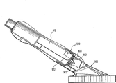
Fig. 1 is the perspective view of medical skin applicator apparatus in accordance with the principles of the present invention, has represented fluid container assembly and applicator head assembly;
Fig. 2 is the decomposition diagram of the skin applicator assembly of Fig. 1;
Fig. 3 is the side view of skin applicator apparatus, has represented that fluid container assembly is in first crossover position;
Fig. 4 is the sectional side view of skin applicator apparatus;
Fig. 5 is the enlarged perspective that expression is installed in the end cap on the fluid housing of fluid container assembly;
Fig. 6 is the enlarged side view that expression is installed in the end cap lock tabs in the axial slot of applicator head assembly;
Fig. 7 is the interior perspective view of applicator framework that the expression end cap is installed in the applicator head assembly;
Fig. 8 is the magnification fluoroscopy cutaway view of relation of the penetrating parts of expression end cap and applicator head assembly;
Fig. 9 is the plane graph of lower surface of the applicator framework of expression applicator head assembly;
Figure 10 is the plane graph of structure of the applicator parts of expression applicator head assembly;
Figure 11 is the side view that is similar to Fig. 3, and the expression fluid container assembly is in second activation point;
Figure 12 is the view that is similar to Fig. 6, and expression lock tabs of end cap when fluid container assembly is in second activation point is fixed in the locking recess of applicator head assembly;
Figure 13 is the view that is similar to Fig. 8, and expression penetrating parts when fluid container assembly is in second activation point pierces through end cap;
Figure 14 is the perspective view of fluid container assembly, and expression is formed at the tap in the end cap lining when being in second activation point;
Figure 15 is the perspective view of another embodiment of skin applicator apparatus of the present invention;
Figure 16 is the decomposition diagram of the skin applicator apparatus of Figure 15;
Figure 17 is the side view of the skin applicator apparatus of Figure 15, and expression fluid housing unit is in first crossover position;
Figure 18 is the sectional side view of skin applicator apparatus when being in first crossover position;
Figure 19 is the perspective view of end cap;
Figure 20 is the upward view of the applicator framework of applicator head assembly;
Figure 21 is the side view that is similar to Figure 17, has represented that the fluid housing unit is in second activation point;
Figure 22 is the side view of another optional embodiment of skin applicator apparatus of the present invention;
Figure 23 is the exploded view of the skin applicator apparatus of Figure 22;
Figure 24 is the side view of skin applicator apparatus when being in second activation point;
Figure 25 is the side view of another optional embodiment of skin applicator apparatus of the present invention, has represented that the fluid housing is in first crossover position;
Figure 26 is the decomposition diagram of the skin applicator apparatus of Figure 25;
Figure 27 is the rotation of expression fluid housing so that the side view that discharges from first crossover position;
Figure 28 is the side view of skin applicator apparatus, has represented that the fluid housing is in second activation point;
Figure 29 is the perspective view of another optional embodiment of skin applicator apparatus of the present invention;
Figure 30 is the side view of the skin applicator apparatus of Figure 19, has represented that fluid container assembly is in first crossover position;
Figure 31 is the decomposition diagram of the skin applicator apparatus of Figure 29;
Figure 32 is the sectional side view of the near-end of skin applicator apparatus, has represented the locking lever of shell body and housing extension portion branch and the relation of trip lever;
Figure 33 is the sectional side view of the far-end of applicator device;
Figure 34 is the side view of fluid housing and end cap;
Figure 35 is the axial view of fluid housing and end cap;
Figure 36 is the applicator framework of applicator head assembly and the sectional perspective view of absorption piece;
Figure 37-the 38th, the other perspective view of applicator framework;
Figure 39 is the upward view of applicator device;
Figure 40 is the sectional side view that is similar to Figure 32, has represented that release locking lever and housing extension portion are divided and the fluid housing moves to second activation point;
Figure 41 is the sectional side view that is similar to Figure 33, has represented the parts relationship after moving to second activation point;
Figure 42 is fluid housing and the perspective view of lining after moving to second activation point;
Figure 43 is the enlarged perspective of the lining after piercing through;
Figure 44 is the side view of another optional embodiment of skin applicator apparatus of the present invention;
Figure 45 is the sectional side view of expression fluid housing when being in first crossover position;
Figure 46 is the sectional side view of expression fluid housing when being in second activation point;
Figure 47 is the perspective view of another optional embodiment of skin applicator apparatus of the present invention;
Figure 48 is the sectional side view of the skin applicator apparatus of Figure 47;
Figure 49 is the decomposition diagram of the skin applicator apparatus of Figure 49;
Figure 51 is the broken section perspective view of another embodiment of skin applicator apparatus of the present invention;
Figure 52 is the perspective view of the optional embodiment of skin applicator apparatus of the present invention, and wherein, the applicator framework has the penetrating parts of circular arrangement;
Figure 53 is the sectional side view of the skin applicator apparatus of Figure 52 when being in first crossover position;
Figure 54 is the sectional side view of skin applicator apparatus when being in second activation point;
Figure 55 is the side view of another optional embodiment of skin applicator apparatus of the present invention;
Figure 56 is the decomposition diagram of the skin applicator apparatus of Figure 55;
Figure 57 is another plane graph of the skin applicator apparatus of Figure 55; And
Figure 58 is the perspective view of end cap of the skin applicator apparatus of Figure 55.
The specific embodiment
The medical skin applicator apparatus of exemplary embodiment and its use will be introduced by medical skin applicator should be used in the medical care process, this medical care comprises that the skin to health applies fluids for sterilization, gel or medicament, is used for preparation, treatment etc.Skin applicator apparatus preferably constitutes and helps fluids for sterilization and be communicated with the skin engaging member of skin applicator apparatus or the fluid of distribution member, thereby can prepare and treat patient's skin surface.Should be known in that skin applicator apparatus can be used for the medical care of certain limit, for example surgical operation, diagnosis and the associated treatment of patient disease and health indisposition.Should also be appreciated that the relative theory of described skin applicator apparatus comprises to skin and apply various medicaments, for example medicine and other fluid.
In the following description, term " nearside " is meant more close doctor's structure division, and term " distally " is meant further from doctor or user's part.In this article, term " patient " is meant patient or other animal.According to the present invention, term " doctor " or " user " typically refer to doctor, nurse or other nursing staff, and can comprise the paraprofessional personnel.
Below explanation comprise the explanation of each embodiment of skin applicator apparatus in accordance with the principles of the present invention, subsequent introduction the device use.
Below with reference to accompanying drawing, in whole accompanying drawings, same parts represented by same reference numerals, and Fig. 1-3 (and in conjunction with Fig. 4 cutaway view) has represented medical skin applicator apparatus in accordance with the principles of the present invention.Device 100 comprises two primary clusterings, i.e. fluid container assembly 102 and applicator head assembly 104, and this applicator head assembly 104 is connected with fluid container assembly 102.Usually, fluid container assembly 102 is used for relative applicator head assembly 104 and moves to second activation point from first crossover position, so that divide dose out powders or fluid to impose on patient.Fluid container assembly 102 comprises: fluid housing 106, and this fluid housing 106 has been determined housing axis " x "; And end cap 108, this end cap 108 is installed on the fluid housing 106 releasedly.Fluid housing 106 has been determined internal chamber 106a (Fig. 4), and this internal chamber 106a is full of medicine, clean solution etc.This medicine comprises germicidal solution, antiseptic solution etc., becomes liquid or gel form.A kind of suitable fluids for sterilization is by Aplicare, and Branford CT makes, trade name is the sterilised liq of Excel-AP.This liquid comprises the iodine of 7.5%w/w, the isopropyl alcohol of 64.5%w/w and 25.3% USP disinfectant, and other is proprietary component.
Fluid housing 106 also defines handle portion 110, is arranged in the cylindrical section 112 and the nipple part 114 in the distally of handle portion 110.Handle portion 110 has fan-shaped lower surface, so that caught by the user, particularly catches by user's a hands.Cylindrical section 112 comprises external circumferential ribs 116, and this external circumferential ribs 116 has been determined the junction of cylindrical section 112 and handle portion 110.External circumferential ribs 116 is as retainer, so that make fluid container assembly 102 with respect to applicator head assembly 104 appropriate location when driving device 100.Nipple part 114 comprises external screw thread 118.
Fluid housing 106 (particularly handle portion 110) can be made by suitable flexible material, so as can compression handles part 110 to discharge fluid.In a preferred embodiment, fluid housing 106 is made by suitable polymers material (for example polypropylene), and makes by common injection moulding technology.Other elastomeric material also can be considered.
Fluid housing 106 also comprises penetrable wall or surface, and the form of this penetrable wall or surperficial precedent such as sealing member or lining 120 is connected with the distal end portion surface of nipple part 114.Lining 120 can be metal or polymeric material, and is installed on the fluid housing 106, makes this housing 106 be full of pharmaceutical liquid subsequently.In a preferred embodiment, lining 120 is paper tinsel linings, and it introduces the nipple 114 of fluid-encapsulated housing 106.In optional form, lining 120 can be fixed in the end cap 108, and sealing thread joint 114 when being used in end cap 108 is installed in fluid housing 106.Lining 120 also can be a dual-layer lining, and one deck is installed on the end cap 108, and another layer is installed on the nipple 114.In optional form, lining 120 can be the Spin welding plastic cap, and the thin-walled of this plastic cap is by Spin welding etc. and be connected with nipple 114.The germicidal solution that comprises ethanol may need plastic cap.Plastic cap can have selected groove shape geometry, and it provides the breakdown point of the sharp point that is used for penetrating parts, so that reduce required puncturing hole.When driving device 100, lining 120 is pierced, so as from fluid housing 106 release medicine or liquid.
Below with reference to Fig. 4-5 and introduce the end cap 108 of fluid container assembly 102 in conjunction with Fig. 2.End cap 108 is cylindrical shape roughly, and has determined outer wall 122 and annular lip 124, and this annular lip 124 is arranged in the far-end of outer wall, and becomes vertical relation with housing axis " x ".Outer wall 122 comprises a pair of axial lead rib 126, and this is arranged to radially relativeness to guiding rib 126, and the axis " x " of longshore current body housing 106 extends.Guiding rib 126 is oriented in predetermined rotational positions place with respect to applicator head assembly 104 with end cap 108, and/or prevent end cap 108 when assembling at applicator head assembly 104 internal rotation.The outer wall 122 of end cap 108 also has pair of locking lug 128, and this is arranged to radially relativeness to lock tabs 128, and leaves guiding rib 126 about 90 °.Each lock tabs 128 is a baseball plate shape, and it has: guiding V-arrangement head, and this V-arrangement head has inclined side surfaces 130; And lateral surfaces 132, this lateral surfaces 132 is stretched out continuously from the V-arrangement head.Lock tabs 128 is fixed on second activation point with fluid container assembly 102.
The annular lip 124 of end cap 108 defines central opening 132, and this central opening 132 allows near the lining 120 that is installed on the fluid housing 106.Annular lip 124 is by the peripheral rib 134 around the periphery of flange 124.Peripheral rib 134 extends preset distance along housing axis " x ", and cooperates with corresponding construction in the applicator head assembly 102, so that be formed on the fluid-tight in the device 100 when driving device 100.End cap 108 has also been determined female thread 136.Female thread 136 cooperates with the external screw thread 118 of fluid housing 106, so that end cap 108 is installed on the fluid housing 106.
Enlarged drawing below with reference to Fig. 2-4 and Fig. 6-7 is introduced applicator head assembly 104.Applicator head assembly 104 comprises applicator framework 138 and applicator parts 140 (for the form of absorption piece), and these applicator parts 140 are installed on the applicator framework 138.The medicated cap supporting axle collar 144 that applicator framework 138 is included in the housing supporting axle collar 142 of near-end and is arranged in the housing supporting axle collar 142 distally.The housing supporting axle collar 142 has been determined internal cavities, and the diameter of the cylindrical section 112 of the diameter of this internal cavities and fluid housing 106 is similar, so that receive this cylindrical section 112 in assembling process.Similarly, the internal diameter determined of the medicated cap supporting axle collar 114 or the size diameter that equals end cap 108.Shown in Fig. 6-7, the medicated cap supporting axle collar 144 also comprises: at least one (preferably a pair of) be conduit 146 to axial radially, and the outer wall that this axial slot 146 passes completely through the medicated cap supporting axle collar 144 extends; And vertically discharging slit 148, this vertically discharges the opposite side of slit 108 in each axial slot 146.Axial slot 146 has been determined relative cam face 150, and this relative cam face 150 tilts to extend with respect to housing axis " x ", and ends at locking recess 152.Axial slot 146 receives the lock tabs 128 of end cap 108, and makes lock tabs 128 to cross conduit 146 in the driving process of device 10.The function of axial slot 146 and vertical slit 148 is with more detailed introduction in the back.
Preferably as shown in Figure 7, the medicated cap supporting axle collar 144 has also been determined inner cannelure 154.Interior groove 154 receives the axial lead rib 126 of end cap 108, and this guiding rib 126 crosses interior groove 154 in the driving process of device 108.Interior groove 154 and axial lead rib rotatably are fixed on fluid container assembly 102 in the applicator head assembly 104.The medicated cap supporting axle collar 144 has also been determined the transverse groove 156 in the internal cavities of the supporting axle collar 144.Transverse groove 156 is arranged as and 134 one-tenth relativenesses of peripheral rib, so that receive this peripheral rib 134 in the driving process of device 100.Transverse groove 156 and peripheral rib 134 have suitable dimension, so that be formed on the sealing member in the internal cavities of the medicated cap supporting axle collar 144 in the driving process of device, return towards fluid housing 106 thereby reduce fluid substantially.
Below with reference to Fig. 8, applicator framework 138 has also determined to be arranged in a pair of parts or the tip 158 of piercing through of the medicated cap supporting axle collar 144 inside.Pierce through parts 158 and determined sharp tip, this sharp tip penetrates lining 120 in the driving process of device 100.It is preferably spaced apart to pierce through parts 158, as shown in the figure.Represented among the figure that two are pierced through parts, but should be known in more or less parts 158 that pierce through can be provided that this also can obtain purpose of the present invention.
Below with reference to Fig. 8-9, applicator framework 138 also comprises throat 160 and the applicator support plate 162 that stretches out from this throat 160.Throat 160 has determined internal holes 160b, from the medicament or the direction of flow applicator parts 140 of fluid housing 106 releases.Applicator support plate 162 supporting applicator parts 140.Support plate 162 comprises centre bore 164, and this centre bore 164 is communicated with (Fig. 9) with the internal holes 160a of throat 160 and first and second conduits 166,168 that are arranged on the support plate lower surface.Centre bore 164 is sized to allow a large amount of relatively medicaments or fluid to be communicated with from this centre bore distribution with first and second conduits 166,168.First conduit 166 is along roughly longitudinal direction extension, and 166 one-tenth vertical relation ground of second conduit 168 and first conduit extend.First conduit 166 has been determined the width bigger than second conduit 168, and the outermost of the drug flux that can make q.s and applicator framework 138 partly (being front-end and back-end) be communicated with.Applicator framework 138 can also determine a plurality of show greatly shown in concentric relation arrange radially or arcuate slots 170.Arcuate slots 170 is communicated with first and second conduits, 166,168 fluids.Arcuate slots 170 is dispensed to medicament on the whole substantially surface of support plate 160, is used to send to applicator parts 140.Like this, medicament is evenly supplied with applicator parts 140 by being determined at the fluid manifold (comprising first and second conduits 166,168, arcuate slots 170 and centre bore 164) in the support plate 162, and therefore this cause evenly imposing on patient.
Applicator parts 140 are installed on the support plate 162.Applicator parts 140 preferably include into the absorption piece of opening, netted urethane foams form, 75+/-10 hole/inches (ppi).Applicator parts 140 can stick on the support plate 160 by bonding agent, welding etc.Applicator parts 140 are arranged to carry the medicament that distributes from fluid container assembly 102.The volume of the absorption piece of applicator parts 140 is arranged to hold the entire contents of fluid container pro rata, thus when imposing on patient skin as fluid reservoir.This can be used in the control release of fluid and reduces the gathering of antibacterial on patient skin.
Preferably as shown in figure 10, when seeing in plane graph, applicator parts 140 have been determined roughly water droplet shape or dolphin nose shape shape.Particularly, support plate 160 and applicator parts 140 have been determined enlarged 172 and slender neck or have protruded fore-end 174 that this slender neck or protrusion fore-end 174 are suspended on this enlarged 172.Enlarged 172 is thought of as to be convenient to medicinal fluid is imposed on relatively large body region.Slender neck part 174 is sized to be positioned at the zone in narrow distally, and for example patient's finger, toe, eye areas etc. are perhaps only needing the fluidic zone of relatively small amount.Enlarged 172 comprises relative roughly convex surface 176, and this convex surface 176 interconnects by arc rear side surface 178.In a preferred embodiment, enlarged 172 has determined that Breadth Maximum " w " is about 2 inches extremely about 4 inches local ellipses.Slender neck or protrusion fore-end 174 have been determined relative concave surface 180, and this concave surface 180 is stretched out continuously from the convex surface 176 of enlarged 172, and it leads to front side arcuate surfaces 182, and this front side arcuate surfaces 182 interconnects concave surface 180.The bow-shaped structural of concave surface 180 helps operating this device 100 around the finger, toe patient etc.Particularly, the radius of curvature of concave surface 180 roughly conforms to the radius of curvature that the partes corporis humani divides, and therefore, applicator parts 140 can rotate and are applied on the health by making concave surface 180 carry out lift-over and pivot with respect to body part.Protrude fore-end 174 determined about 0.5 inch to about 1.5 inches minimum widith " w2 ".Applicator absorption piece 140 determined from about 3 inches to about 6 inches length " l ".
Introduce the operation of device 100 below.In use, the doctor is fixed on the bottom side of fluid housing 106 and catches applicator 100 with one hand by making his or her at least three fingers.Then, thumb is arranged in the top of applicator framework 138 so that catch framework 138.Forefinger is fixing with respect to applicator framework 138, and thumb and forefinger pull to fixed forefinger simultaneously, so that produce predetermined connection power between fluid container assembly 102 and applicator housing unit 104.Like this, fluid housing unit 102 will with respect to applicator head assembly 104 along the longitudinal direction (shown in the direction arrow among Figure 11 " z ") move to its second activation point.The scope of lengthwise movement can limit with the engagement that housing supports the axle collar 142 by peripheral retainer or rib 116.
Below with reference to Figure 12, in the axially-movable process of fluid housing 106, the lock tabs 132 of end cap 108 is crossed the axial slot 146 of applicator framework 138.Should know, vertical release slit 148 of contiguous axial slot 146 make cam face 150 (this cam face 150 has been determined axial slot 146) can by with the cam-engaged of the inclined side surfaces 130 of lock tabs 128 to extrinsic deflection, thereby lock tabs 128 is packed in the locking recess 152.Should be known in that cam face 150 provides resistance to a certain degree for the motion of lock tabs 128 process axial slot 146.This resistance provides the tactile indicators of installing 100 states to the doctor, thereby has reduced to install the 100 unexpected probabilities that drive.By lock tabs 128 is loaded in the locking recess 152, fluid container assembly 102 remains on second activation point shown in Figure 11-13.In the progressive relatively while of fluid housing unit 102, the parts 158 that pierce through of applicator head assembly 104 penetrate lining 120, as shown in figure 13.Should also be appreciated that in second activation point, peripheral rib 134 is packed in recess 156 (see figure 7)s, so that form the basic fluid-tight of this position, thereby makes fluid minimum to returning of fluid housing 106.
Pierce through parts 158 and can be arranged to cover fully lining 120.Also can select, pierce through parts 158 and be arranged to penetrate two holes in lining 120, as shown in Figure 14.Two opening O1, O2 producing by this action will produce the fluid conduit, and an opening is used for making germicidal solution pour in the throat of applicator framework 136 under the pressure that the doctor produces by suitable compressed fluid housing 106.The second opening O2 distributes by allowing air admission fluid housing 106 to help fluid, thereby makes its internal balance, prevents to produce the airbond of container contents, and feasible release fluids more as one man.The said modules location definition is second or " driving " position.
The fluid that is loaded in the fluid housing 106 can flow in the applicator framework 138 after lining 120 breaks immediately.The suitable compression of fluid housing 106 makes a part of content wherein discharge, and compresses the content that can make in the air replacement fluid container 106 and discharge.Allow air admission to will speed up fluid flow like this.Therefore, fluid can measure or pump, and in twice to three times pumping, approximately the entire contents of 60ml is all discharged from fluid housing 106.
With reference to figure 8-9, fluid moves to applicator support plate 162, and distributes by centre bore 164 and first and second conduits 166,168 and arcuate channels 170.Compressed fluid housing 106 can force antibacterial to enter in the hole of absorption piece a little.The structure of applicator plate 162 can be sent to absorption piece 142 with whole container contents in about two to three seconds, promptly almost carry out fluid fillers and balance immediately, thus the even asymmetric profile of the whole sponge of moistening.
In use, many profiles absorption piece 140 conforms to patient's whole body contour or form substantially.For example, the nose that protrudes the front end shape will help eyes, ear, finger, toe, groin or other determines the preparation of form.In addition, profile or cross section conform to patient's the arm or the radial surface of lower limb.Compared with prior art, the prolongation overlay length L of applicator 70 (promptly longer sponge interface) can cover about 4 times of areas the single stroke of the motion from a side to opposite side.This has increased about productivity ratio of 400 percent than the prior art applicator with flat profile, and it has saved time and labour force, particularly when relating to a plurality of operation.
As mentioned above, applicator device 100 of the present invention comprises key feature and the advantage that does not have in the prior art.Singlehanded trigger mechanism and singlehanded the driving have been improved convenience and productivity ratio-do not need to handle snap ring or pre-trigger mechanism, and do not need to remove other parts before using.But adopt level and smooth driving and single deck tape-recorder to buckle trigger mechanism.Minimized number of components has reduced complexity and manufacturing cost.In addition, fluid housing 106 moistening more quickly, and the integrated fluid manifold in applicator framework 138 can make even moistening of sponge structure and balance fill, and no matter fluid viscosity how.Therefore, bigger sponge allows applicator counter-rotating use, faster preparation and control release of fluid.Multipurpose sponge with outline shape can conform to any patient's form, and integrated sponge strip/protrusion front end has improved the motility of common sponge strip and the speed of applicator.
Below with reference to Figure 15-18, represented another preferred embodiment of the present invention among the figure.Skin applicator apparatus 200 comprises fluid container assembly 202 and is installed in applicator head assembly 204 on the fluid housing unit 202.Fluid container assembly 202 comprises the fluid housing 206 and the axle collar 208 that stretches out continuously from this fluid housing 206.Preferably, fluid housing 206 is a domed shape, and can comprise accordion structure, so that housing 206 can be compressed, is loaded on wherein fluid with discharge.Can consider that according to special-purpose, body housing 206 can have various structures, for example cylindricality, rectangle, ellipse, polygon etc.Fluid housing 206 can be by elastomeric material or above-mentioned any material and is formed.Fluid container assembly 202 also comprises lining 210 and end cap 212, and this end cap 212 is installed on the axle collar 208 of fluid housing 206.Lining 210 is preferred for the form of foil seal, and can stick on the axle collar 208 and/or end cap 212 inside.
Preferably as shown in figure 19, end cap 212m does not have screw thread, and can be fixed on the axle collar 208 by bonding agent, welding, adhesive etc.End cap 212 is included in a pair of radially lock tabs 214 relatively on its outer surface, and is preferably spaced apart 180, and end cap 212 also comprises axial rib 216.Lock tabs and axial rib 216 work in lock tabs and the similar mode of axial rib with the embodiment of Fig. 1-14.
With reference to figure 16-18, applicator head assembly 204 comprises applicator framework 218, and this applicator framework 218 has throat 220 and the applicator support plate 222 that is connected with this throat 220.Throat 220 has determined inside opening 224, and this inside opening 224 allows medicament to lead to support plate 222, and proximal flange 226 is arranged, and this proximal flange 226 preferably is sized to be caught by doctor's finger.A pair of axial slot 228 with corresponding vertical release slit 230 is extended in the wall of throat 220.Axial slot 228 receives lock tabs 214, and makes lock tabs 214 can cross conduit 228 when apparatus drives.Throat 220 penetrates tip or parts 230, and this penetrates tip or parts 230 extend upward from applicator support plate 222 by inside opening 224.Tip 230 is expressed as single conical component, and but, tip 230 also can take any sharp shape maybe can be for a plurality of.
With reference to Figure 18 and 20, applicator support plate 222 comprises a plurality of holes 232, and these holes 232 are communicated with inside opening 224 fluids of throat 220, and center arrangement is in the center of applicator plate 222.Applicator support plate 222 comprises the first and second linear conduits 230,232 on its lower surface, this first and second linear conduit 230,232 one-tenth be vertical relations mutually roughly, and carries out centralized positioning along the major axis " y " and the minor axis " z " of support plate 222.Applicator support plate 222 also comprises the grid type structure, has a plurality of narrow intersection conduit 234 on its bottom side surface and the linear conduit 230,232 that intersects.
In use, fluid container assembly 202 moves to second activation point of Figure 20 from first crossover position of Figure 17.Preferably, the doctor catches the flange 226 of applicator framework 218 with forefinger and middle finger, and its palm is positioned to against the upper surface of fluid housing 206.In this motor process, lock tabs 214 trans-axial conduits 228, and be fixed in mode similar to the above among the locking recess 228a of axial slot 228.Simultaneously, penetrating parts 230 puncture linings 210 are so that the fluid that allows to be loaded in the fluid housing 206 is discharged.Then, fluid flows through the inside opening 224 and the hole 232 of throat 220.Then, the fluid medicament flows through linear conduit 230,232, and further flows through the lattice types structure 234 on the lower surface that is arranged in applicator framework 218.By this structure, whole substantially absorption piece 236 all soaks into medicament.Then, device 200 carries out disinfection, so that medicament is imposed on patient's skin.Fluid housing 206 can compress, so that discharge the fluid medicament, perhaps medicament can be supplied with by gravity by upset fluid housing 206.
Below with reference to Figure 22-24, represented optional embodiment of the present invention among the figure.This embodiment embodiment basic and Fig. 1 is similar.But, according to this embodiment, skin applicator apparatus 300 comprises fluid housing 302, and this fluid housing 302 has a pair of radially relative lock rib 304 on the outer surface that is arranged in cylindrical section 306.Lock rib 304 is the substantial linear structure, and the expansion arched ribs part 304a at its far-end is arranged.Applicator framework 306 comprises the axle collar 308, and this axle collar 308 has locking conduit 310, and the shape of this locking conduit 310 is roughly corresponding with the lock rib 304 of fluid housing 302 with the position.Particularly, locking conduit 310 is a substantially linear, and comprises the first and second arcuate channels part 310a, 310b.In first crossover position of fluid housing 302 shown in Figure 22, the arched ribs part 304a that respectively enlarges of lock rib 304 is positioned at the first arcuate channels part 310a that locks conduit 310, and be defined in wherein, thereby fluid housing 302 is fixed on first crossover position releasedly by the inner boundary of conduit part 310a.When this installed 300 when the decision driving, the doctor made fluid housing 302 advance with respect to applicator framework 306.In this motor process, lock rib 304 is crossed and is locked conduit 310, and therefore, the surface of determining locking conduit 310 is passed through so that allow to enlarge flank 304a, and concerned in the second arcuate channels part 310b that packs into buckle to extrinsic deflection.In this position, lock rib 304 is fixed in the locking conduit 310, thereby fluid housing 302 is fixed in second activation point of Figure 24.In all others, device 300 is similar with the device 100 of Fig. 1 on function.
Figure 25-28 has represented another preferred embodiment of the present invention.Skin applicator apparatus 400 is roughly similar with the described device of the embodiment that combines Figure 15 200.But, according to this embodiment, fluid housing 402 is included at least one or a pair of radially relative lock tabs 404 on the distally axle collar 406.In this embodiment, device 200 does not have end cap; But, it is contemplated that device 200 can have end cap, this end cap has aforementioned lock tabs 404.Lock tabs 404 is packed in the corresponding roughly z shape slit 408, and this slit 408 is determined in the throat 410 of applicator framework 412.The feature of Z-shaped slit 408 is second vertical components 418 that have first vertical component 414, horizontal component 416 and stretch out from this horizontal component 416.Vertical component 414,418 comprises locking recess 420,422.Vertically discharge each vertical component 414,418 that slit 424 is arranged to close z shape slit 408.Discharge wall surface that slit 424 allows to determine vertical component 414,418 to extrinsic deflection, so that allow lock tabs 404 to pack in the locking recess 420,422.In use, the axle collar 406 of fluid housing 402 is positioned at the throat 410 of applicator framework 412, and lock tabs 404 is arranged in the vertical component 414 of z shape slit 408 and is loaded on locking recess 420.In this position, fluid housing 402 remains in the applicator framework 412, and cooperates with the wall surface of definite locking recess 420 by lug 404 and be fixed on first crossover position releasedly.When decision driving device 400, the doctor makes fluid housing 402 rotate with respect to applicator framework 412 along the direction of direction arrow " a ", as shown in figure 27.Lock tabs 404 is subjected to the pressure from locking recess 420, therefore, discharges slit 424 and allows to determine that the surface of locking recess 420 is along outward direction deflection.Make lock tabs 404 leave locking recess 420 required power and provide the tactile indicators of fluid housing 402 towards the motion of second activation point to the doctor.The horizontal component 416 that lock tabs 404 is crossed z shape slit 408 to second vertical component, 418 positions aligning, as shown in Figure 27.Then, the doctor applies power at a distance to fluid housing 402, so that make fluid housing 402 advance to the position shown in Figure 28 with respect to applicator framework 412.In this motor process, lock tabs 404 is crossed second vertical component 418 that forms slit 408, and in the locking recess 422 of packing into.Lock tabs 404 should be known in that in this motor process determining the wall surface of vertical component 418 can be to extrinsic deflection because vertical release slit 424 is provided, so that can be packed in the locking recess 422.Therefore, locking recess 422 keeps lock tabs 404, makes medicament be dispensed to second activation point in the absorption piece 426 thereby fluid housing 402 remained on.
Below with reference to Figure 29-31, represented the skin applicator apparatus of another optional embodiment of the present invention among the figure.Skin applicator apparatus 500 comprises fluid container assembly 502 and the applicator head assembly 504 that is connected with this fluid container assembly 502.Fluid container assembly 502 comprises fluid housing 605, the end cap 508 and the lining 510 that are connected with this housing 506.Fluid housing 506 comprises: at least one cylindricality locking projections 512, perhaps also can select, and a part of locking projections 512 extends radially outwardly with respect to housing axis " x "; And peripheral rib 514, this peripheral rib is in the distally of locking projections 512.Fluid housing 506 also comprises: at its external screw thread of far-end; And a plurality of wing plates that are radially spaced 518, these wing plates 518 are protruding from the wall of fluid housing 506 at the nearside of screw thread 516.Lining 510 is the paper tinsel lining preferably, and can be fixed on the fluid housing 506 by any aforementioned manner.End cap 508 comprises female thread 520, and this female thread 520 cooperates with the external screw thread 516 of fluid housing 506, so that end cap 508 is fixed on (Figure 33) on the fluid housing 506.End cap 508 also is included in a plurality of inclined teeth 519 (Figure 41 and Figure 35) at its mouth place.In this fixed position, in the inclined teeth 519 that is radially spaced wing plate 518 insertions or the end cap 508 of nipping on fluid housing 506 outer surfaces, unexpectedly remove (Figure 35) from fluid housing 506 so that prevent end cap 508.End cap 508 has also been determined distal shaft loop section 508c, and this distal shaft loop section 508c has the diameter that reduces, and its function is with more detailed introduction in the back.
Again with reference to figure 30-32, fluid container assembly 502 comprises that also housing extension portion divides 522, and this housing extension portion divides 522 to be connected with fluid housing 506.In a kind of preferred installation method, housing extension portion is divided the 522 a pair of cylindrical openings 524 that comprise the wall that passes it, is used to receive the locking projections 512 of fluid housing 506 and becomes the buckle relation with it.Also it is contemplated that and otherwise make housing extension portion divide 522 to be connected with fluid housing 506.Housing extension portion is divided 522 locking levers 526 that also are included in its outer wall.Locking lever 526 is used for fluid housing 506 is remained on first activation point not releasedly.Locking lever 526 has been determined locking frame plate 528, and is used for along its loose-joint butt radially to intrinsic deflection, so that discharge locking frame plate 528.But housing extension portion is divided the 522 manually-operated buttons of also having determined at its near-end 530.Button 530 has been determined the diameter that divides 522 remainder to reduce with respect to housing extension portion, and the guide rail 532 that in axial direction extends along its outer surface is arranged.Guide rail 532 guarantees single aligned position, so that assembling.
Skin applicator apparatus 500 also comprises shell body 534.Shell body 534 is fixed on the applicator head assembly 504, and is sized to hold fluid housing 506 and housing extension portion divides 522.The contour shape that shell body 534 is determined has a plurality of spaced apart rib 536 on its outer surface, so that the doctor catches.Shell body 534 has been determined the centre bore 538 in its proximal end, divides 522 manually-operated button 530 but this centre bore receives housing extension portion, and this shell body 534 has also been determined key shape opening 540, is used to receive housing extension portion and divides 522 guide rail 532 (Figure 31).By this relation, housing extension portion divides 522 to be used for opposite shell body 534 and to move along longitudinal direction roughly, but fixing with respect to shell body 534 rotations.
Shell body 534 also defines the opening 542 (Figure 31) in its outer wall, is used for the locking lever 526 of local at least housing case extension 522.Opening 542 has been determined distally locking surface 544, and this distally locking surface 544 and housing extension portion are divided locking frame plate 528 engagements (Figure 32) of 522 locking lever 526 when fluid housing 506 is in first crossover position.Shell body 534 comprises trip lever 546, and this trip lever 546 extends in the opening 542 of shell body 534, and divides 526 one-tenth stacked relation of locking lever of 522 with housing extension portion.Trip lever 546 can around it loose-joint butt radially inwardly pivot rotate so that with locking lever 526 engagements and make this locking lever 526 carry out respective pivot to rotate, so that discharge the engagement of locking frame plate 528 and locking surface 544.In this orientation, housing extension portion divide 522 and fluid housing 506 can move to second activation point along the longitudinal direction.
Introduce applicator head assembly 504 below with reference to Figure 33 and 36-38.Applicator head assembly 504 comprises applicator framework 548 and the absorption applicator parts 550 that are installed on this applicator framework 548.Applicator framework 548 comprises throat 552, and this throat 552 has determined to be used to receive the internal holes of end cap 508 and fluid housing 506.There is at least one the opening 552a (Figure 31) in its outer wall in throat 552, is used to hold the corresponding locking projections 554 of shell body 534, so that applicator framework 548 is securely fixed on the shell body 534.
Preferably shown in Figure 33,36-37, inner collar 556 that is installed on the transverse wall 557 and a plurality of penetrating parts 558 of stretching out from this inner collar 556 are arranged in throat 552 inside.Preferably, penetrating parts 558 is 4, and arranges along crossing plane, determines four quadrants when piercing through lining 510 with convenient penetrating parts 558.Also can consider greater or less than four penetrating parts 558.Particularly, each penetrating parts 558 extends to cusp 560, and each cusp 560 of penetrating parts 558 arranges around central axis " c " with the adjacent spaces open relation, as shown in the figure.
Below with reference to Figure 36-38, applicator framework 548 has also been determined first and second conduits 562,564, and this first and second conduit 562,564 is arranged near inner collar 556 peripheries and the top and the bottom section of close throat 552.First and second conduits or manifold 562,564 helps medicament respectively or fluid directly leads to the front-end and back-end of applicator parts 550.First conduit 562 is semi-circular cross-section roughly, and extends to the upper end or the front end of applicator framework 548 from the semi-circular channel 562a of contiguous inner collar 556 peripheries.Arc or the crescent opening 564a of second conduit 564 from transverse wall 557 stretches out, and is communicated with the bottom or the rear end of applicator framework 548.Applicator framework 548 has also been determined center expanded hole 566, and this center expanded hole 566 extends to the lower surface of applicator framework 548.Hole 566 is communicated with first and second conduits, 562,564 fluids, and is sized to a large amount of fluids to be expelled to the central area of absorption piece 550.
Below with reference to Figure 36 and 39, the shape of absorption piece 550 is basic similar with above-mentioned absorption piece, preferably becomes to absorb the form of sponge, foam plastics etc.Absorption piece 550 is installed on the lower surface of applicator framework 548 by common mode.Absorption piece 550 comprises a plurality of isolated slits 568, and this spaced apart slit 568 passes completely through the thickness extension of absorption piece 550 along the central axis of absorption piece 550.Slit 568 is as zero draught excluder, and promptly slit 568 is used for not keeping closing when absorption piece is exerted pressure, but exerts pressure when pressure is applied on the absorption piece 550, so that allow fluid to flow through it.
In use, the doctor catches device 500 with one hand, preferably around shell body 534.Then, in order to drive this device 500, the trip lever 546 of doctor's operation housing body 534, and radially inward direction " i " (shown in figure 32) is pushed trip lever 546.Trip lever 546 rotates around its loose-joint butt pivot, so that divide 522 locking lever 526 engagements with housing extension portion, thereby makes locking lever 526 carry out corresponding inside motion.When the inside pivots of locking lever 526 rotated, the locking frame plate 528 of locking lever 526 discharged the engagement of the locking surface 544 of it and shell body 534.In this position, housing extension portion divides 522 and fluid housing 506 freely-movable along the longitudinal direction.
Below with reference to Figure 40, then, the doctor by his hands the rear portion or make by his thumb and to divide the button 530 of 522 proximal end to advance in housing extension portion.Required driving force (about 8-12 lbs, when needing can by thumb drives) make housing extension portion divide 522 and fluid housing 506 with respect to shell body 534 and applicator head assembly 504 along distal direction advance (Figure 41).At this moment with particular reference to Figure 42-43, the motion of the distal direction of fluid housing 506 makes lining 510 be penetrated by four penetrating parts 558, and this causes lining 510 to pierce through into four quadrant part 510a-d.Related stroke makes paper tinsel peel off to the sidewall of puncture cylinder, thereby can make whole diameters be used for fluid flow.When lining 510 broke, the medicament in fluid housing 506 almost was expelled in first and second conduits 562,564 by the internal holes of inner collar 556 simultaneously, is used for being dispensed to the expanded hole 566 of applicator framework 548.Expanded hole 566 is a large-size, like this, overcomes the viscous force relevant with medicament by fluid mass.This makes fluid " to pour out " by gravity in several seconds, does not promptly need the compressed fluid housing.In addition, first conduit 562 is guided fluid the slender neck part of applicator parts into, and second conduit 564 is guided fluid into Background Region.Fluid layer is distributed on the absorption piece 550 like this, uniformly.And first and/or second conduit 562,564 can form balance by allowing air admission applicator framework 548 inside in applicator framework 548, thereby guarantees the medicament of enough flows.Preferably, in first and second conduits 562,564 any one or two can provide passage, thereby at compression absorption piece 550 is to allow air to return by each opening or passage 562a, 564a by conduit 562,564 to enter applicator framework 548, so that ventilate to atmosphere.Figure 33 represented that first conduit 562 stretches out by the passage 562a around the axle collar 556 and with applicator framework 548 internal communication.The assembler difference relevant with the parts of device 500 is enough to allow air to be ventilated.And at activation point, the distally axle collar 508c of end cap 508 leaks (see figure 4) so that prevent towards applicator framework near-end around the outer surface gas-tight seal of inner collar 556.This structure also can be used as frictional fit or interference engagement, and this frictional fit or interference engagement make the fluid housing remain on second activation point.In the process of compression absorption piece 550, a certain amount of medicament can return by the opening 564a of passage 562a or transverse wall, so that adapt to fluid volumes change.Should also be appreciated that the engagement of the relevant position lock hole 570 in the locking shielding part 528 that fluid housing 506 can be by locking lever 526 and the outer wall of shell body 534 remains on second activation point (for example seeing Figure 40).
As mentioned above, applicator device of the present invention comprises key feature and the advantage that does not have in the prior art.Prior art needs two handss to use and drives very energetically, the invention provides singlehanded the triggering and very little pressure-driven (be similar to drive and push pen).This makes the degree of fatigue of going smoothly little, and do not need " crack " sound.Do not need snap ring or prevent and to start, and before using, do not need to remove parts than large driving force.In fact, single step, extruding-release carry lock to prevent unexpected the driving, and the parts of minimal amount will reduce complexity and manufacturing cost.In addition, the applicator handle of prior art is level and smooth, linear and inclination 45 degree, causes controlling uncomfortable.On the contrary, ergonomic handle of the present invention has rib, even so that comfortable and also can drag when moistening.The hourglass shape profile of handle and rounded end are fit to the hands of size arbitrarily, and between 30-40 and preferably 35 degree reduce handle angle make it possible to better near and control.Although prior art comprises restricted conduit or net, transmit so that postpone fluid, wide mouth bottle of the present invention can make Fungicidal substance overcome surface tension and be expelled to absorption piece fast.The discharge of bottle content is also quickened by double piercing device, and this double piercing device produces the air admission mouth on the fluid layer of fluid housing.The spongiform of prior art becomes symmetry, so that to there not being manifold to compensate.On the contrary, " c conduit " of the present invention manifold opposite end of moistening asymmetric sponge equably.Although prior-art devices in when counter-rotating because less sponge capacity and low fluid transmit and work relatively poorly, and the present invention can reverse and use and quicker preparation, because bigger sponge is as the fluidic storage tank of transmission fast.Prior art comprises square sponge head, and is difficult on the form of certain profile and uses.But, the multipurpose sponge of certain profile conforms to any patient's form, and all-in-one-piece sponge cervical region partly provides the motility of common sponge strip and the speed of applicator.The thickness T of sponge is the twice of prior art thickness, and this has reduced injury patient's danger, and longer sponge length L can be prepared quickly.
According to doctor's special-purpose and/or hobby, the parts of medical skin applicator apparatus can be made by the material that is suitable for medical application, for example polymer or metal (as rustless steel).Can consider to utilize semi-rigid and rigid polymer and elastomeric material to make, for example the polypropylene of molded medical grade.But, it will be appreciated by those skilled in the art that other material and the manufacture method that are suitable for assembling and making are also suitable according to the present invention.
Figure 44-46 has represented optional embodiment of the present invention.According to present embodiment, skin applicator apparatus 600 comprises the optional mechanism that is used for fluid container assembly is fixed on releasedly first crossover position.Particularly, housing extension portion divides 602 to be included on the outer surface of button 606 and to become the radially a pair of neighboring local ribs 604 of relativeness.At first crossover position of fluid housing 610, rib 604 surpasses shell body 608, shown in Figure 44-45.Shell body 608 has been determined the restriction opening 612 in its proximal end, and the inside dimension of this restriction opening 612 or internal diameter divide effective cross-section size 602, that comprise local ribs 604 less than housing extension portion.Therefore, local ribs 604 prevents that housing extension portion from dividing 602 openings 612 by shell body 608.When this installs 666 when the decision driving, the doctor divides 602 button 606 to apply distally pressure to housing extension portion, this make local ribs 604 and/or housing extension portion divide 602 and the respective wall of shell body 608 carry out bending, distortion etc., so that allow local ribs 604 by restriction opening 612, thereby make fluid housing 610 can move to its second activation point, as shown in figure 46.It is also conceivable that housing extension portion divides 602 can be fixed on second activation point by internal lock lug or recess are provided in shell body 608.This inner tabs or recess can have suitable dimension, so that mesh, receive with 604 one-tenth fixed relationships of local ribs.Absorption piece 614 comprises a plurality of openings 616, and the thickness that these openings 616 pass completely through absorption piece extends, as shown in Figure 45.Opening 616 replaces the slit of previous embodiment.
Another feature of the applicator device 600 of Figure 44 is the layout of handle component with respect to the applicator head assembly.Particularly, the handle component of device moves with respect to the applicator head assembly, operates this device around this helps in the working position.Particularly, the internal part of shell body 608 and formation fluid container assembly is along handle axis " j " layout, as shown in figure 44.The applicator head assembly 620 that comprises applicator framework 622 carries out coaxial arrangement around axis " k ".Preferably, axis " k " is with respect to the vertical mobile preset distance of axis " j ", but preferably becomes parallel relation.This departs from makes that the doctor can keep concerning with the best 35 degree of patient, be used for this simultaneously and depart from and modification space can be arranged, thereby keep " zone of comfort ", for example with respect to patient skin, doctor's hands leaves patient, so that the operability around improving in the working position.
Figure 47-48 has represented another optional embodiment of skin applicator apparatus of the present invention.According to present embodiment, skin applicator apparatus 700 is fixed on its crossover position releasedly by detachable label 702.Particularly, but the housing extension portion that is installed on the fluid housing 706 is divided 704 transverse holes 708 that are included in the manually-operated button 710.Can discharge label 702 and be arranged in transverse holes 708, and prevent in being positioned at this hole 708 time housing extension portion divide 704 and the fluid housing (not shown) installed advance, be fixed on first crossover position thereby will install 700 releasedly.Can discharge label 702 can remove from transverse holes 708, so that can drive this device, and makes fluid container assembly can move to second activation point.Can discharge label 702 can be by arbitrarily firm or flexible material manufacturing, and preferably includes handle 712, so that caught by the doctor.The applicator head assembly preferably includes the longitudinal channels 716 in its lower surface, so that bigger volumetrical fluid flow is provided.Conduit 716 can be connected with the slit or the opening that pass absorption piece 714 extensions.
Figure 49-50 has represented another optional embodiment of the present invention, is used to distribute cleaning sterilization agent (for example chlohexidine gluconate/alcoholic solution).The cleaning sterilization agent has proposed problem to the doctor, because it is applying the very difficult overlay area that changes, back.Skin applicator apparatus 800 is basic with to combine the described skin applicator apparatus of Figure 29 similar, but also comprises the dyeing chamber, is used for dyestuff or coloring agent introducing medicament or fluid.Particularly, fluid housing 802 has the paper tinsel lining 804 (as mentioned above) that is connected with it and is removably mounted on first end cap 806 on the housing 802.Device 800 also comprises second end cap 808 that is installed on first end cap 806.In a kind of preferred structure, first end cap 806 comprises external screw thread 810, and second end cap 808 comprises corresponding female thread 812, and this female thread 812 can carry out screw-threaded engagement with external screw thread 810, so that second end cap 808 is fixed on first end cap 806.Second end cap 808 also comprises the paper tinsel lining 814 that is fixed on end cap inside.Under second end cap 808 was installed in state on first end cap 806, chamber 816 was determined between the corresponding paper tinsel lining 814,804 of two parts.Dyestuff or coloring agent 818 are stored in this chamber 816.Suitable dyestuff Shi ﹠amp; The green #3 dyestuff of C, by ParchemTrading Ltd.White Plains, NY 10601 makes.In the driving process of device, the penetrating parts 820 of applicator framework 822 pierces through two linings 814,804, and therefore, the dyestuff 818 in chamber 816 mixes in the process through applicator framework 822 with medicament.Like this, dyestuff makes medicament or antibacterial catch desirable color.
Figure 51 has represented a kind of optional embodiment, and wherein, dyestuff sheet 850 is arranged in applicator framework 822.Preferably, this dyestuff sheet 850 that comprises dyestuff is arranged in the inner conduit 854 of contiguous absorption piece 856.When medicament sent absorption piece 856 to, the dyestuff sheet contacted with this medicament.The dyestuff sheet can comprise the described dyestuff in conjunction with the embodiment of Figure 49-50.
Figure 52-54 has represented another optional embodiment of the present invention.Skin applicator apparatus 900 comprises the optional mechanism that is used to cut the paper tinsel lining.Preferably, the form of the penetrating parts of this circular arrangement of mechanism or tip 902, this penetrating parts or tip stretch out from the inner collar 904 of applicator framework 906, shown in the perspective view among Figure 52.This circular arrangement is used for forming the circular opening at the paper tinsel lining 908 that is installed on the fluid housing 910.According to this embodiment, fluid housing 910 provides the roughly inside partition wall 912 of longitudinal direction extension of edge.Similarly, inner collar 904 can provide vertical wall 914.When fluid housing 910 moves to the second position of Figure 54, interior wall 912,914 is used for the wall part engagement with the paper tinsel lining 908 that is cut by the penetrating parts of circular arrangement, and makes it rotate to the position of rotation (shown in Figure 54) that roughly aligns with longitudinal axis from initial lateral attitude.In this position, medicament can not cut paper tinsel lining 908 and stop ground, flows through applicator framework 906 in unrestricted mode.Preferably, the interior wall 912,914 in fluid housing 910 and inner collar 904 radial deflections of applicator framework 906 or vertically stagger, like this, by moving to second activation point, the cutting wall part of paper tinsel lining is trapped between two walls 912,914.In others, the effect of present embodiment and the previous embodiment of Figure 29 are similar.
Below with reference to Figure 55-58, represented optional in accordance with the principles of the present invention embodiment among the figure.Skin applicator apparatus 1000 comprises fluid container assembly 1002, and this fluid container assembly 1002 ties up on the applicator 1004 by anchor line (string).More particularly, fluid container assembly 1002 comprises fluid housing 1008, paper tinsel lining 1010 and end cap 1012, but these end cap 1012 screw threads are installed on the fluid housing 1008.End cap 1012 comprises female thread 1014, and this female thread 1014 can carry out screw-threaded engagement with the external screw thread 1016 (Figure 58) of fluid housing 1008.Applicator 1004 comprises O shape ring adapter 1018, and anchor line (string) 1006 is connected with this O shape ring adapter 1018.O shape ring adapter 1018 is positioned on the cervical region 1020 of end cap 1012, and remains in wherein by the peripheral rib 1022 in cervical region 1020 outsides.Applicator 1004 comprises the penetrating parts 1024 of circumferential array, and with the homotaxis in the previous embodiment, lining 1010 is used to puncture.Applicator 1004 comprises a plurality of isolated bulb shape applicators top 1026, and there are a plurality of isolated openings 1028 on these applicator tops 1026, are used for the branch dose out powders.Circular absorption sponge 1030 can be installed on the applicator top 1026.In use, applicator 1004 can pivot on the assembly 1002, and is fixed on the fluid container 1002 by peripheral rib 1022 is loaded in the annular notch 1032 in the applicator 1004.It is also contemplated that alternate manner, comprise interference engagement, be clasped, bayonet socket connection etc.The installation of applicator 1004 makes tip penetrate lining, thereby drives this device 1000.
Should be known under the situation that does not break away from the spirit and scope of the present invention, can carry out various variations and change form and details.Therefore, above-mentioned explanation is not construed as limiting the invention, and just example illustrates the preferred embodiments of the present invention.In the described scope and spirit of the present invention as accessory claim, those skilled in the art it is contemplated that other variation.Although required and introduced the present invention in detail and especially according to Patent Law, its appropriate protection scope will propose in accessory claim.