CN101147188B - Motion-based tracking method and system in image processing - Google Patents
Motion-based tracking method and system in image processing Download PDFInfo
- Publication number
- CN101147188B CN101147188B CN2006800090302A CN200680009030A CN101147188B CN 101147188 B CN101147188 B CN 101147188B CN 2006800090302 A CN2006800090302 A CN 2006800090302A CN 200680009030 A CN200680009030 A CN 200680009030A CN 101147188 B CN101147188 B CN 101147188B
- Authority
- CN
- China
- Prior art keywords
- image
- motion
- captures
- display
- user
- Prior art date
- Legal status (The legal status is an assumption and is not a legal conclusion. Google has not performed a legal analysis and makes no representation as to the accuracy of the status listed.)
- Expired - Fee Related
Links
Images


Classifications
-
- A—HUMAN NECESSITIES
- A63—SPORTS; GAMES; AMUSEMENTS
- A63F—CARD, BOARD, OR ROULETTE GAMES; INDOOR GAMES USING SMALL MOVING PLAYING BODIES; VIDEO GAMES; GAMES NOT OTHERWISE PROVIDED FOR
- A63F13/00—Video games, i.e. games using an electronically generated display having two or more dimensions
- A63F13/20—Input arrangements for video game devices
- A63F13/21—Input arrangements for video game devices characterised by their sensors, purposes or types
- A63F13/213—Input arrangements for video game devices characterised by their sensors, purposes or types comprising photodetecting means, e.g. cameras, photodiodes or infrared cells
-
- A—HUMAN NECESSITIES
- A63—SPORTS; GAMES; AMUSEMENTS
- A63F—CARD, BOARD, OR ROULETTE GAMES; INDOOR GAMES USING SMALL MOVING PLAYING BODIES; VIDEO GAMES; GAMES NOT OTHERWISE PROVIDED FOR
- A63F13/00—Video games, i.e. games using an electronically generated display having two or more dimensions
-
- A—HUMAN NECESSITIES
- A63—SPORTS; GAMES; AMUSEMENTS
- A63F—CARD, BOARD, OR ROULETTE GAMES; INDOOR GAMES USING SMALL MOVING PLAYING BODIES; VIDEO GAMES; GAMES NOT OTHERWISE PROVIDED FOR
- A63F13/00—Video games, i.e. games using an electronically generated display having two or more dimensions
- A63F13/55—Controlling game characters or game objects based on the game progress
- A63F13/56—Computing the motion of game characters with respect to other game characters, game objects or elements of the game scene, e.g. for simulating the behaviour of a group of virtual soldiers or for path finding
-
- G—PHYSICS
- G06—COMPUTING; CALCULATING OR COUNTING
- G06F—ELECTRIC DIGITAL DATA PROCESSING
- G06F3/00—Input arrangements for transferring data to be processed into a form capable of being handled by the computer; Output arrangements for transferring data from processing unit to output unit, e.g. interface arrangements
- G06F3/01—Input arrangements or combined input and output arrangements for interaction between user and computer
- G06F3/017—Gesture based interaction, e.g. based on a set of recognized hand gestures
-
- G—PHYSICS
- G06—COMPUTING; CALCULATING OR COUNTING
- G06F—ELECTRIC DIGITAL DATA PROCESSING
- G06F3/00—Input arrangements for transferring data to be processed into a form capable of being handled by the computer; Output arrangements for transferring data from processing unit to output unit, e.g. interface arrangements
- G06F3/01—Input arrangements or combined input and output arrangements for interaction between user and computer
- G06F3/03—Arrangements for converting the position or the displacement of a member into a coded form
- G06F3/041—Digitisers, e.g. for touch screens or touch pads, characterised by the transducing means
- G06F3/042—Digitisers, e.g. for touch screens or touch pads, characterised by the transducing means by opto-electronic means
- G06F3/0425—Digitisers, e.g. for touch screens or touch pads, characterised by the transducing means by opto-electronic means using a single imaging device like a video camera for tracking the absolute position of a single or a plurality of objects with respect to an imaged reference surface, e.g. video camera imaging a display or a projection screen, a table or a wall surface, on which a computer generated image is displayed or projected
-
- G—PHYSICS
- G06—COMPUTING; CALCULATING OR COUNTING
- G06T—IMAGE DATA PROCESSING OR GENERATION, IN GENERAL
- G06T7/00—Image analysis
- G06T7/20—Analysis of motion
- G06T7/215—Motion-based segmentation
-
- A—HUMAN NECESSITIES
- A63—SPORTS; GAMES; AMUSEMENTS
- A63F—CARD, BOARD, OR ROULETTE GAMES; INDOOR GAMES USING SMALL MOVING PLAYING BODIES; VIDEO GAMES; GAMES NOT OTHERWISE PROVIDED FOR
- A63F2300/00—Features of games using an electronically generated display having two or more dimensions, e.g. on a television screen, showing representations related to the game
- A63F2300/10—Features of games using an electronically generated display having two or more dimensions, e.g. on a television screen, showing representations related to the game characterized by input arrangements for converting player-generated signals into game device control signals
- A63F2300/1018—Calibration; Key and button assignment
-
- A—HUMAN NECESSITIES
- A63—SPORTS; GAMES; AMUSEMENTS
- A63F—CARD, BOARD, OR ROULETTE GAMES; INDOOR GAMES USING SMALL MOVING PLAYING BODIES; VIDEO GAMES; GAMES NOT OTHERWISE PROVIDED FOR
- A63F2300/00—Features of games using an electronically generated display having two or more dimensions, e.g. on a television screen, showing representations related to the game
- A63F2300/10—Features of games using an electronically generated display having two or more dimensions, e.g. on a television screen, showing representations related to the game characterized by input arrangements for converting player-generated signals into game device control signals
- A63F2300/1087—Features of games using an electronically generated display having two or more dimensions, e.g. on a television screen, showing representations related to the game characterized by input arrangements for converting player-generated signals into game device control signals comprising photodetecting means, e.g. a camera
- A63F2300/1093—Features of games using an electronically generated display having two or more dimensions, e.g. on a television screen, showing representations related to the game characterized by input arrangements for converting player-generated signals into game device control signals comprising photodetecting means, e.g. a camera using visible light
-
- A—HUMAN NECESSITIES
- A63—SPORTS; GAMES; AMUSEMENTS
- A63F—CARD, BOARD, OR ROULETTE GAMES; INDOOR GAMES USING SMALL MOVING PLAYING BODIES; VIDEO GAMES; GAMES NOT OTHERWISE PROVIDED FOR
- A63F2300/00—Features of games using an electronically generated display having two or more dimensions, e.g. on a television screen, showing representations related to the game
- A63F2300/60—Methods for processing data by generating or executing the game program
- A63F2300/6045—Methods for processing data by generating or executing the game program for mapping control signals received from the input arrangement into game commands
Landscapes
- Engineering & Computer Science (AREA)
- Theoretical Computer Science (AREA)
- Multimedia (AREA)
- General Engineering & Computer Science (AREA)
- Human Computer Interaction (AREA)
- Physics & Mathematics (AREA)
- General Physics & Mathematics (AREA)
- Computer Vision & Pattern Recognition (AREA)
- User Interface Of Digital Computer (AREA)
- Image Analysis (AREA)
- Studio Devices (AREA)
- Position Input By Displaying (AREA)
- Closed-Circuit Television Systems (AREA)
- Vehicle Body Suspensions (AREA)
- Burglar Alarm Systems (AREA)
Abstract
In one implementation, a first captured image is accessed. The first captured image includes (1) a first display produced at a first point in time, and (2) a user interacting with the first display and not part of the first display. A second captured image is accessed. The second captured image includes (1) a second display produced at a second point in time, and (2) the user interacting with the second display and not part of the second display. The first captured image and the second captured image are compared. The motion of the user is determined based on a result of the comparing of the first captured image and the second captured image. The determined motion of the user is related to a portion of one or more of the first and second captured images.
Description
Technical field
The disclosure partly relates to Flame Image Process, particularly relates to the motion in the detected image.
The information that projection of various systems or explicit user expectation are interactive indirectly at least with it.For example, computing machine uses mouse positioning cursor and shown document interaction indirectly in the document of demonstration through display document and user expectation on the monitor of being everlasting.Such computing machine can also use projector that document is projected on the projection screen, rather than shows described document on monitor.As another example, touch screen computer allows the user to pass through at the position touch monitor by image indication itself, and for example, the specific factor in the image that touch shows is so that select this key element, and is directly more interactive with the image execution that shows.
Disclosed one embodiment passes through detection user's motion and imports based on this user's motion generation, allows the direct and image interaction shown or projection of user.For example, can use video-game generation and display image, and, wanting to select under the situation of certain icon the user, the user can point to the icon in this image.Disclosed system detects user's motion, detected motion is associated with the selection of icon and will represents that the input of the icon that the user has selected offers described application program.This system uses phase machine testing user's motion.
According to a general aspect, the image that visit at first captures.The image that at first captures comprises (1) in first showing that very first time point produces, and (2) and first show interactive and are not the users of first part that shows.The image that secondly captures of visit, next image that captures comprise (1) in second showing that second time point produces, and (2) and second show interactive and are not the users of second part that shows.The image that at first captures and next image that captures.According to comparative result, determine user's motion to the image that at first captures and next image that captures.With user's the motion of determining with at first with next image that captures in one or more in parts of images connect each other.
The embodiment of above-mentioned general aspect can comprise one or more in the following characteristic.For example, can
At first can comprise the image and next image that captures that at first capture are carried out absolute difference operation or light stream operation with next image that captures.At first with next image that captures can comprise produce described result and, described result can be the image of expression user's motion with the motion relevant with one or more objects during first and second show.Can carry out the geometric transformation operation to this result.
The result of the image that at first captures based on the comparison and next image that captures determines that user's motion can be included in the motion that makes described user among this result and isolate mutually with the motion relevant with one or more objects during first and second show.
The image of the motion that the one or more objects in can visiting expression and first and second showing are relevant.In described result, the image of the motion that the one or more objects in user's motion and the mutual isolation of motion relevant with first and second one or more objects in showing can being comprised described result shown with first and second with expression are correlated with compares.
The image of the motion that the one or more objects in visiting expression and first and second showing are relevant can comprise: visit and first shows the first corresponding display image; Visit shows the second corresponding display image with second; With, the image of the motion that the one or more objects in generating expression and described first and second showing are relevant.By described first display image and described second display image are carried out the absolute difference operation, the image of the motion that the one or more objects in can generating expression and first and second showing are relevant.Optionally, by first display image and second display image are carried out the light stream operation, the image of the motion that the one or more objects in can generating expression and described first and second showing are relevant.
Can be to the image execution stand-by period compensation operation of the expression motion relevant with one or more objects during first and second show.
According to another general aspect, system comprises the moving image detection module and the comparison module of seizure.The moving image detection module of catching is configured to, the image that visit at first captures, wherein, the image that at first captures comprises that (1) is according to the instruction group of being carried out by calculation element, show in first of very first time point generation, and (2) and the first demonstration interaction, and be not the user of first part that shows.The moving image detection module of catching also is configured to, the image that secondly visit captures, next image that captures comprises that (1) is according to the instruction group of being carried out by calculation element, in second showing that second time point produces, and (2) and second show interactive and are not the users of second part that shows.The moving image detection module of seizure also is configured to, and by image and next image that captures of at first capturing are carried out relatively, generates and represents at first and the image of the motion between the image that secondly captures.Comparison module is configured to, according to the image of the one or more motion of objects during representative is shown about first and second with represent first with next image that captures between the image of motion carry out the result who compares, the image that the generation representative of consumer is moved.
The embodiment of above-mentioned general aspect can comprise the one or more of following characteristic.For example, system can comprise the display image motion detection block, it is configured to visit described first display image, visit described second display image, with, by described first display image and described second display image being compared the image that generates the relevant motion of the one or more objects of representative in showing with described first and second.
System can also comprise camera, be configured to: (1) catches the described image that at first captures, and the image that this at first captures is offered the moving image detection module of seizure, with, (2) catch the described image that secondly captures, and the image that secondly this capture is offered the moving image detection module of seizure.In addition or optionally, system can comprise the display and the calculation element of display image, it is configured to carry out one group of instruction, to produce first and second display images.
System can comprise the stand-by period compensating module, is configured to representing the image about the one or more motion of objects in first and second demonstrations to carry out the stand-by period compensation operation.System can also comprise the geometric transformation module, is configured to representing at first and the image of the motion between next image that captures execution geometric transformation operation.
Even only carried out above description here, still, can realize various aspects, embodiment and characteristic in one or more modes with a mode.For example, can using method, the device that installs, is used for manner of execution or instrument or treatment facility, program or other instruction groups, the device that comprises program or instruction group and computer-readable medium one or more, realize various aspects, embodiment and characteristic.For example, computer-readable medium can comprise instruction, software, image and other data.
In the accompanying drawings and the description below, one or more embodiments of the detail are carried out elaboration.According to description and accompanying drawing, and, will understand other characteristics according to claim.
Description of drawings
Figure 1A shows first interactive system.
Figure 1B shows second interactive system.
Fig. 1 C shows the 3rd interactive system.
Fig. 1 D shows the 4th interactive system.
Fig. 1 E shows the 5th interactive system.
Fig. 2 determines user movement for being used for, and the motion that will determine is as the process flow diagram of the example of the processing of the input of application programs.
Fig. 3 is the block diagram of the structure of interactive system.
Fig. 4 A shows first display image.
Fig. 4 B shows second display image.
Fig. 4 C shows the composograph of first and second display images of Fig. 4 A-4B.
Fig. 4 D shows the first display image motion diagram corresponding with first and second display images of Fig. 4 A-4B.
Fig. 4 E shows the second display image motion diagram corresponding with first and second display images of Fig. 4 A-4B.
Fig. 5 A shows the image that at first captures.
Fig. 5 B shows the image that secondly captures.
Fig. 5 C show Fig. 5 A-5B at first with the composograph of next image that captures.
Fig. 5 D shows at first corresponding with next image that the captures image motion figure that at first captures with Fig. 5 A-5B.
Fig. 5 E shows the image motion figure that secondly capture corresponding with the seizure image of Fig. 5 A-5B.
Fig. 6 A shows the first user movement figure.
Fig. 6 B shows the second user movement figure.
Fig. 7 is the block diagram of another structure of interactive system.
Embodiment
In a specific embodiment, video game application programs generate a plurality of images and, this projected image of computer system is given the user.The user plays games with the image interaction that as them is exactly virtual reality demonstration and projection by the image front that enters projection.For example, the user can wave facing to the target that is included in the projected image as object.In this example, embodiment carries out waving of user and detects, and determines that the user waves facing to target, and will represent that the input that the user waves facing to target offers video game application programs.Then, video game application programs generates suitable image to carry out projection in response to receiving the input that the user waves facing to target.
When the user waved, this embodiment can also comprise that projected image and user's a sequence image detects waving of user by using the camera seizure.This embodiment also visits a series of projected images that do not have the user.This embodiment determines the motion in each sequence image, and the motion of relatively having determined in this sequence image, so that with user's motion isolation (being also referred to as " segmentation ").This embodiment uses the knowledge of its target location to determine that user's motion attempts to wave facing to target really, and this is determined to offer video game application programs as input.
Because projected image must be enough bright so that people or camera are felt, so the variation of lighting condition can influence the display quality of projected image with respect to the ambient light rank.Otherwise the outward appearance contrast of projected image (apparent contrast) may be too low, so that can not feel.Camera may have the dynamic range lower than human eye.Therefore, in order camera to be caught comprise the image of projected image, need the brightness necessary of the brightness ratio of projected image bright for the people can feel.For example, catch the image that comprises projected image in order to make camera, need projected image brighter than the rank (for example, sunlight or top light) of ambient light, wherein, the rank meeting of ambient light (for example, along with the sun fell within a day) changes.Must be the same with the rank of ambient light bright with image projection, perhaps bright than the rank of ambient light may be unpractical, and/or expensive.
But the variation of local lighting condition does not obviously influence or reduces the ability that embodiment detects user movement.This is due to the fact that promptly embodiment is by the motion isolation in user movement and the projected image is determined user movement to small part.The variation of local lighting condition can make the display quality of projected image descend, and can weaken the ability that camera is caught projected image.But because the user is reflected abundant light, therefore, the variation of local lighting condition generally can obviously not influence the ability that camera is caught user movement.Therefore, even the sequence image of catching does not comprise the motion in the projected image, the sequence image of seizure still comprises user's motion.
In addition, in the present embodiment, camera is caught image with a sampling rate, makes any variation of lighting condition between successive frame to ignore.The variation of lighting condition generally occurred in a few minutes or several hours, and the sampling rate of camera can be, for example, p.s. 30 images.Therefore, present embodiment in successive frame, capture usually similar lighting condition and, the motion between these frames is determined usually the variation of illumination aspect and motion to be obscured.The variation of local lighting condition detects the not obviously influence of ability of user movement to present embodiment, the fact that the ability that perhaps can not make present embodiment detect user movement obviously reduces, allow present embodiment when local lighting condition changes, continue to detect user's motion.
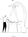
Figure 1A-1E shows the example of different interactive system 100,120,130,140 and 150.Figure 1A shows and comprises the system 100 that image is presented at the display device (for example, projector 102 and display screen 104) that (is called " display image ") on the display screen 104.Camera 110 can according to sampling rate, for example p.s. 30 images, catch image.Can generate display image by the application program that resides on the calculation element 106, perhaps, can generate display image by external application.In this discussion, display image is said " being shown ".But very clear, image also can be projected.Also should be clear, other embodiment needn't carry out projection to image.For example, can use LCDs.
The parts of interactive system 100 can cause for example different system of Figure 1A-1E according to a lot of different deployment arrangements.With reference to Figure 1A, display screen 104 is positioned at user 108 fronts, and projector 102 and camera 110 are positioned at user 108 back.Therefore, user 108 is between projector 102 and display screen 104.Therefore, user 108 can block or partial occlusion by the display image of projector 102 projection on display screen 104.
With reference to Figure 1B, system 120 has the projector 102 that is positioned on the user 108, the camera 110 that is positioned at the display screen 104 of user 108 fronts and is positioned at user 108 back.Such configuration can reduce or eliminate the part of being blocked by user 104 in the display image.
With reference to Fig. 1 C, system 130 has projector 102 and the camera 110 that is positioned on the user 108, and display screen 104 is positioned at below the user 108.Shown in Fig. 1 C, for example, display screen can be ground.
With reference to Fig. 1 D, system 140 has projector 102 and the camera 110 that is positioned on the user 108, and is positioned at the display screen 104 on the desktop 112.User 108 still can block display image limited, generally reduce to minimum part.
With reference to Fig. 1 E, system 150 has the projector 102 that is positioned at desk 114 the insides.The 102 pairs of display images of projector are carried out projection, make display image device 116 (for example, the catoptron) reflection that is reflected, and are presented on the display screen 104.Display screen 104 is positioned on the desktop of desk 114, and camera 110 is positioned on the user 108.User 108 is not blocked display image.Can make calculation element 106 be positioned at desk 114 the insides alternatively.
Can consider other configurations.Many variations can be arranged, and wherein, camera can be placed on such position so that this camera can catch comprise at least display screen 104 and with the image of the user's 108 who is presented at the display image interaction on the display screen 104 a part.
Shown in Figure 1A-1E, display device comprises projector 102 and display screen 104.But display device also can comprise, for example, plasma display, LCD (LCD), cathode ray tube (CRT) display or automatic stereoscopic display device.
With reference to Fig. 2, handle 200 and can be used for determining user 108 motion, and be used for the input of user's 108 that will be definite motion as application programs.Handle 200 and can use the various system implementations that comprise system 100.Although can use other system, for the purpose of sake of clarity, coupling system 100 is described and is handled 200.To handling using system 100 in the process that 200 embodiment carries out description, intention is not to carry out restriction to handling 200.
Handling 200 comprises the image (202) that visit at first captures and visits the image (204) that secondly captures.Can carry out seizure with the user's 108 of the image of 110 pairs of at least a portion display screens 104 of camera and at least a portion and display screen 104 interactions image.The image of catching can be stored in the frame buffer, and can be from the image of frame buffer visit seizure.
Then, image that at first captures and the image that next captures are carried out relatively (206).According to image that at first captures and the image that next captures are carried out result relatively, determine user 108 motion (208).Then, make definite user movement with at first with next image that captures in an one or more part relevant (210).Below Fig. 3 is being carried out in the process of description, the operation of handling 200 embodiment is carried out is more fully described.
With reference to Fig. 3, it shows the structure 300 of system.Though can use other system, for the purpose of sake of clarity, coupling system 100 comes description scheme 300.Using system 100 is not attempted limiting structure 300 in this embodiment of description scheme 300.
Simultaneously, display device 310 shows (for example, projection) display image 304.The display image 311 of projection be displayed on display screen 104 (not shown)s and, user's 108 (not shown)s and display image 304 interactions.In the present embodiment, user 108 is by motion and display image 304 interactions.For example, user 108 can be stretched to hand or touch the object in the display image 304.
Camera 110 is caught and is comprised the display image 311 of projection and user 108 image 311.Camera 110 offers the image 314 of catching the moving image detection module 316 of the seizure of calculation element 106.Camera 110 can directly offer seizure image 314 the moving image detection module 316 of seizure.Optionally, the image 314 of seizure can be stored in the frame buffer, and the moving image detection module 316 of seizure can be from the image 314 of this frame buffer visit seizure.The position of user 108 in the image 314 of catching changes in time.For example, the difference between the position of the user 108 in the continuous capturing image 314 has defined user 108 motion.Prove absolutely more that as reference Fig. 5 A-5E 316 pairs of the moving image detection modules of seizure are caught image 314 and carried out relatively, and produce moving image Figure 31 8 of the seizure that is used for discerning the motion of catching image 314.Because in fact catching image 314 comprises user 108 and display image 304, therefore the motion of identification comprises user 108 motion and the motion in the display image 304 in the moving image Figure 31 8 that catches.
In certain embodiments, synchronization module 312 can be used to make the demonstration of display image 304 and camera 110 to catch image synchronization.Some display device 310 (for example, comprises that digital light processing (digitallight processing, display device DLP)) can sequentially show the red, green, blue component of described display image 304.When the order that can not detect the red, green, blue component of described display image 304 when human eye showed, camera 110 can be caught the variable part of red, green, blue component.Therefore, the red, green, blue component of the display image 304 of the seizure in the image 314 of continuous capturing may be different, thereby the moving image detection module 316 that causes catching detects such motion of catching in the image 314, it does not belong to the motion in the display image 304, but it is the motion of being created by display device 310.Therefore, synchronization module 312 can be used to guarantee that camera 110 is every uniform portion of catching seizure red, green, blue component in the image 314.
In certain embodiments, in order to generate motion diagram, display image motion detection block 306 and 316 pairs of two images of moving image detection module of catching are carried out comparison operation, for example, and the absolute difference operation.For gray level image, the amplitude (for example, absolute value) of the difference of the value by calculating two each pixels in the image is determined motion.Perhaps, for coloured image, (motion diagram is determined in for example, the red, green, blue amplitude of the difference of) value summation by each color channel to each pixel of being used for two images.By the motion diagram of two images being carried out absolute difference operation generation identification is carried out in the motion that occurs in the zone of image.For example, the motion in the zone of the gray scale sequence of image will produce very big absolute difference, and very big absolute difference will occur as a bright spot in motion diagram.
In other embodiments, in order to generate motion diagram, for example, display image motion detection block 306 and 316 pairs of two images of moving image detection module of catching are carried out the light stream operation.Usually, optical flow algorithm is carried out and is distinguished the motion in the image (for example, having changed the object of position in image), and constitutes the vector (for example, direction/orientation and amplitude) of the speed of the motion of being distinguished in the representative image.Therefore, optical flow algorithm is not only determined motion to occur in image, and travel direction and amplitude in definite image.Therefore, by the motion diagram of two images being carried out light stream operation generation appearance, orientation and the amplitude of the motion in the image are carried out identification.
In addition, perhaps, motion detection block 306 and 316 can be carried out motion diagram and expand and the erosion filtering operation.Expand and corrode filtering operation, determine the value of this individual pixel also according to the value of the surrounding pixel of individual pixel.In dilation operation, filter window is through one group of pixel around individual pixel and this individual pixel, and makes the value of this individual pixel equal to have in the filter window value of peaked pixel.In corroding computing, filter window is through one group of pixel around individual pixel and this individual pixel, and makes the value of this individual pixel equal to have in the filter window value of the pixel of minimum value.
Carry out among the embodiment of absolute differences operation in motion detection block 306 and 316, represent the pixel of moving image Figure 31 8 motion among both of display image motion diagram 308 and seizure to belong to motion in the display.Therefore, such pixel is not classified as the motion in the representative of consumer motion diagram 322.On the contrary, only the pixel of the motion among moving image Figure 31 8 of representative seizure is attributed to user 108 motion, and therefore, these pixels are endowed the value of the motion in the representative of consumer motion diagram 322.
Carry out among the embodiment of light stream operation in motion detection block 306 and 316, motion among the moving image Figure 31 8 that catches, that obviously be different from the motion in the display image motion diagram 308 is attributed to user 108 motion, and is retained among user movement Figure 32 2.For example, (1) is if the difference of amplitude aspect surpasses amplitude thresholds; Perhaps, (2) if the difference of aspect, orientation (for example direction) surpasses the orientation threshold value, thinks that then motion among the moving image Figure 31 8 that catches obviously is different from the motion in the display image motion diagram 308.Therefore, in such embodiments, even can in the zone that also shows the motion in the display, detect user 108 motion.
Existence is used for other mechanism with the motion isolation of user 108 motion and display.For example, can from catch image 314, deduct corresponding display image 304, thereby generate user images.Then, can generate user movement figure according to continuous user images.
The user's 108 of Que Dinging motion (for example, as representative in user movement Figure 32 2) is used as user's input of application programs 302.For example, application program 302 can receive user movement Figure 32 2, and according to user movement Figure 32 2, determines that user 108 waves facing to the target in the display image 304.In response to user 108 facing to determining that target is waved, application program 302 generates appropriate display images 304, and this display image is offered display image detection module 306 and display device 310.
Can be with the figure shown in Fig. 4 A-4E, 5A-5E and the 6A-6E, the image processing techniques of the motion that is used for determining user 108 carried out describe.For example, such image processing techniques can be carried out by the structure shown in Fig. 3 300.Therefore, for the purpose of sake of clarity, although can carry out identical image processing techniques with system with other structures,, under the situation of structure 300 shown in Figure 3, the figure shown in Fig. 4 A-4E, 5A-5E and the 6A-6E is carried out description.With reference to the structure shown in Fig. 3 300, intention was not to being used to carry out structure and system's execution restriction of the image processing techniques of describing in conjunction with the figure shown in Fig. 4 A-4E, 5A-5E and the 6A-6E when figure among Fig. 4 A-4E, 5A-5E and the 6A-6E was carried out discussion.
As to the briefly introducing of Fig. 4 A-4E, Fig. 4 A-4B shows the sequence display image.Fig. 4 C shows the composograph at the sequence display image shown in Fig. 4 A-4B, and Fig. 4 D-4E illustrates the display image motion diagram of the motion that is used for discerning the sequence display image shown in Fig. 4 A-4B.
As to the briefly introducing of Fig. 5 A-5E, Fig. 5 A-5B shows the sequence capture image.Fig. 5 C shows the composograph at the sequence capture image shown in Fig. 5 A-5B, and Fig. 5 D-5E illustrates the motion diagram image pattern of the seizure of the motion that is used for discerning the sequence capture image shown in Fig. 5 A-5B.
As to the briefly introducing of Fig. 6 A-6B, Fig. 6 A-6B shows the corresponding user movement figure of motion diagram image pattern with the seizure of the display image motion diagram of Fig. 4 D-4E and Fig. 5 D-5E.
Fig. 4 A shows first display image 304 (a), Fig. 5 A show comprise first display image 304 (a) and with the user's 108 of display interaction the corresponding image that at first captures 314 (a).Application program 302 generates first display image 304 (a) at moment t-1, and first display image 304 (a) is offered display image motion detection block 306 and display device 310.Shown in Fig. 4 A, first display image 304 (a) comprises ball 402.Display device 310 is presented at first display image 304 (a) on the display screen 104, and, user 108 and display interaction.Camera 110 catch comprise first display image 304 (a) and with the user's 108 of display interaction the image that at first captures 314 (a).Therefore, the image 314 (a) that at first captures comprises the ball 402 of the user 108 and first display image 304 (a).
Fig. 4 B shows second display image 304 (b), that Fig. 5 B shows is corresponding, comprise second display image 304 (b) and with the user's 108 of display interaction the image that secondly captures 314 (b).Application program 302 generates second display image 304 (b) at moment t, and second display image 304 (b) is offered display image motion detection block 306 and display device 310.Shown in Fig. 4 B, second display image 304 (b) comprises and the identical ball 402 of first display image 304 (a).But with respect to the position of ball 402 in first display image 304 (a), the position of ball 402 in second display image 304 (b) keeps left.For the diverse location of ball 402 in first display image 304 (a) and second display image 304 (b) is described, Fig. 4 C shows the composograph 403 of first display image 304 (a) and second display image 304 (b).Any parts that appear at composograph 403 among Fig. 4 C and be not by structure 300 or structure 300 generate.It just proposes for purposes of illustration on the contrary, in order that the diverse location of ball 402 in first display image 304 (a) and second display image 304 (b) is shown.Broken circle 402 (a) is represented the position of ball 402 in first display image 304 (a), and broken circle 402 (b) is represented the position of ball 402 in second display image 304 (b).
Display device 310 shows second display image 304 (b) on display screen 104, and user 108 carries out interactive with display.110 pairs in camera comprises second display image 304 (b) and carries out with the user's 108 of display interaction the image that secondly captures 314 (b) catches.Therefore, next image that captures 314 (b) comprises the ball 402 of the user 108 and second display image 304 (b).Shown in Fig. 5 B, with respect to the position of user 108 in the image 314 (a) that at first captures, keep right in position in the image 314 (b) that user 108 captures secondarily, and with respect to the position of ball 402 in the image 314 (a) that at first captures, the position in the image 314 (b) that ball 402 captures secondarily keeps left.For user 108 and ball 402 diverse location in image 314 (a) that at first captures and image 314 (b) that next captures is described, Fig. 5 C shows the composograph 501 of image 314 (a) that at first captures and the image 314 (b) that next captures.Any parts that appear at composograph 501 among Fig. 5 C and be not by structure 300 or structure 300 generate.On the contrary, it just proposes for purposes of illustration, in order that user 108 and ball 402 diverse location in image 314 (a) that at first captures and image 314 (b) that next captures is shown.The position of user profile 108 (a) representative of consumer 108 in the image 314 (a) that at first captures of dotted line, the position in the image 314 (b) that user profile 108 (b) representative of consumer 108 of dotted line captures secondarily.Broken circle 402 (c) is represented the position of ball 402 in the image 314 (a) that at first captures, and broken circle 402 (d) is represented the position in the image 314 (b) that ball 402 captures secondarily.
Difference between second display image 304 (b) and first display image 304 (a) has been created the animated appearance in the display (that is motion).Position and difference ball 402 position in second display image 304 (b) between of ball 402 in first display image 304 (a) represents ball in moment t-1 and the motion between the t constantly.More generally, the representative of the difference between first display image 304 (a) and second display image 304 (b) is in moment t-1 and between the t, in display constantly motion.
First display image 304 (a) and second display image 304 (b) are offered display image motion detection block 306, to determine the motion among display image 304 (a) and 304 (b).Display image motion detection block 306 is carried out first display image 304 (a) and second display image 304 (b) relatively, and creates the display image motion diagram 308 that is used for the motion of two images 304 (a) and 304 (b) is carried out identification.Fig. 4 D shows by first display image 304 (a) and second display image 304 (b) are carried out the example that absolute difference is operated the display image motion diagram 308 (a) that generates.By Fig. 4 D as seen, identify, moving 404 at the region memory of display image 304 (a) and 304 (b) by first display image 304 (a) and second display image 304 (b) being carried out the display image motion diagram 308 (a) that the absolute difference operation generates.
Fig. 4 E shows by first display image 304 (a) and second display image 304 (b) are carried out the example that the display image motion diagram 308 (b) that generates is operated in light stream.By Fig. 4 E as seen, by first display image 304 (a) and second display image 304 (b) are carried out the display image motion diagram 308 (b) that the light stream operation generates, use vector 406 to identify existence, direction and the amplitude of the motion in display image 304 (a) and 304 (b).
As discussed above, with respect to the position of user 108 in the image 314 (a) that at first captures, keep right in the position in the image 314 (b) that user 108 captures secondarily.Belong to the interaction of user and display in the difference aspect user 108 the position.For example, it is the same to seem to carry out simulation (for example, virtual) volleyball match, and for ball 402 is carried out batting, user 108 is near ball 402.User 108 in the image 314 (a) that at first captures the position and the difference representative of consumer 108 between the position in the image 314 (b) that captures secondarily of user 108 in moment t-1 and the motion between the t constantly.
Image 314 (a) that at first captures and the image 314 (b) that next captures are offered seizure image detection module 316.Seizure 316 pairs of images that at first capture 314 of image detection module (a) and the image 314 (b) that next captures are carried out relatively, and create the moving image Figure 31 8 that is used for the motion of two images 314 (a) and 314 (b) is carried out the seizure of discerning.Fig. 5 D shows by image 314 (a) that at first captures and the image 314 (b) that next captures are carried out the example that absolute difference is operated moving image Figure 31 8 (a) of the seizure that generates.By Fig. 5 D as seen, moving image Figure 31 8 (a) of seizure identifies the motion 500 that belongs to the user and the motion 502 in the display.Fig. 5 E shows by image 314 (a) that at first captures and the image 314 (b) that next captures are carried out the example that moving image Figure 31 8 (b) of the seizure that generates is operated in light stream.By Fig. 5 E as seen, moving image Figure 31 8 (b) of seizure the motion 504 using vector to identify to belong to the user and the motion 506 in the display.The optical flow algorithm that is used for generating moving image Figure 31 8 (b) of seizure (for example can pick out the total object of the image 314 (a) that at first captures and the image 314 (b) that next captures, user 108 and ball 402), and, carry out relatively position to object total in the image 314 (a) that at first captures and the image 314 (b) that next captures, so that generate the vector of the motion that is used for recognition image 314 (a) and 314 (b).
With reference to Fig. 7, show the structure 700 of system.Except the following difference of pointing out, structure 700 is roughly the same with the structure 300 that combines Fig. 3 description.
In certain embodiments, the position of the feature among the moving image Figure 31 8 that catches and the position of the character pair in the display image motion diagram 308 have deviation, for example, this is because camera 110 relative display screen 104 rotations, and projector 102 (for example differs from one another axle with camera 110, shown in Figure 1A, camera 110 is on projector 102, therefore projector 102 is not coaxial with camera 110), perhaps, because to be used to generate the resolution of seizure image 314 of moving image Figure 31 8 of seizure different with the resolution of the display image 304 that is used to generate display image motion diagram 308.Therefore, in certain embodiments, calculation element 106 comprises geometric transformation module 702, the data conversion that is used for the moving image Figure 31 8 that will catch (for example, distortion, rotation, convergent-divergent, displacement) be moving image Figure 70 4 that conversion is caught, make that the feature among moving image Figure 70 4 that conversion catches is aimed at the character pair in the display image motion diagram 308.Therefore, the geometric transformation operation is carried out compensation to the camera 110 of putting upside down installation, to carrying out compensation with the camera 110 of projector 102 disalignments installation, perhaps, the display image that is projected on the catoptron 116 is carried out compensation, and wherein, catoptron 116 reflexes to display image on the display screen 104.For example, the geometric transformation operation can comprise: pixel is carried out moved or rearrange; Size to moving image Figure 31 8 of catching is carried out convergent-divergent; Motion value is carried out interpolation; And/or, motion value is carried out extrapolation.
Calibration process can be used for the geometric maps between the coordinate of the seizure image determining display image and comprise display image.Then, the feature that geometric maps can be used for definite moving image Figure 31 8 that will catch is aimed at needed geometric transformation operation with the character pair in the display image motion diagram 308.
Calibration process can be included on the display screen 104 and show known pattern, for example, and some grid or chessboard.Camera 110 is caught the image that comprises pattern, and, calculate the position of catching the pattern in the image.Then,, can use the key element of catching in the image,, the geometric maps between the coordinate of the coordinate of catching image and display image be carried out defining with respect to the position of the corresponding key element in the display image at each pixel of catching in the image.
In addition, perhaps, calibration process can be included in before display pattern or the part pattern, shows blank image in short-term.The moving image detection module 316 of catching can come check pattern by detecting the variation (for example, motion) of catching in the image.
As mentioned above, moving image Figure 31 8 of 702 pairs of seizure of geometric transformation module carries out the geometric transformation operation.But in another embodiment, before seizure image 314 was provided for the moving image detection module 316 of seizure, 702 pairs of geometric transformation modules were caught image 314 and are carried out the geometric transformations operation.
In certain embodiments, stand-by period compensating module 706 is stored in a period of time in the impact damper with display image motion diagram 308, this time with will compensate the stand-by period that display image motion diagram 708 offers before the comparison module 320 stand-by period and equate.Therefore, stand-by period compensation display image motion diagram 708 almost reaches comparison module 320 simultaneously with moving image Figure 70 4 that corresponding conversion is caught.In another embodiment, stand-by period compensating module 706 is stored in a period of time in the impact damper with display image 304, and this time equated with stand-by period before display image being offered display image motion detection block 306.
In addition, perhaps, stand-by period compensating module 706 can be used for the difference between the sampling rate of the frame rate of display device 310 and camera 110 is carried out compensation.For example, the frame rate of display device 310 may be bigger than the sampling rate (for example, time shutter) of camera 110.Therefore, single seizure image may comprise the exposure to a plurality of display images 304.For this species diversity between the sampling rate of the frame rate of display device 310 and camera 110 is carried out compensation, stand-by period compensating module 706 can be combined into a plurality of continuous display image motion diagrams 308 the single stand-by period and compensate display image motion diagram 708.The quantity with the display image motion diagram 308 that produces single stand-by period compensation display image motion diagram 708 of being combined is chosen as quantity Matching with the displayed image that shows during a sampling period of camera 110 (for example, exposure).
Can use logic " 0R " computing, the display image motion diagram 308 that uses the absolute difference operation to generate is carried out combination.In other words, be defined as the representative motion if be combined with the pixel in a plurality of display image motion diagrams 308 that generate stand-by period compensation display image motion diagram 708 any one, then the respective pixel in the stand-by period compensation display image motion diagram 708 will be defined as the representative motion.
Perhaps, can be by following processing, the display image motion diagram 308 that uses the light stream operation to generate is carried out combination, promptly, give a range of movement to each pixel in the stand-by period compensation display image motion diagram 708, make this range of movement that is used for this pixel comprise and be combined to generate the motion that the stand-by period compensates a plurality of display image motion diagram 308 respective pixel of display image motion diagram 708.
Calibration process can be used for determining that display image is sent to the stand-by period between the moment that moment of display device 310 and correspondence image captured by camera 110.Calibration process can comprise blank display image demonstration a period of time, then, show the display image that comprises pattern.The display image that comprises pattern is sent to the moment executive logging of display device 310, and will carries out relatively in this moment, thereby determine the stand-by period with the moment that in corresponding seizure image, detects pattern.
In certain embodiments, application program 302 directly offers calculation element 106 with display image motion diagram 308.In such embodiments, do not need display image motion detection block 306.In addition, although Fig. 3 and Fig. 7 are shown in application program 302 beyond the calculation element 106,, in certain embodiments, application program 302 resides in the calculation element 106, and operation thereon.Illustrate as these embodiment, function described herein can be carried out in disparate modules and different device.Therefore, along with function is transferred to another device from a device, the interface between the device can change.
In certain embodiments, after generating user movement Figure 32 2, user movement Figure 32 2 is offered the application program 302 that generates display image 304 as input.Application program 302 uses user movement Figure 32 2 to detect user 108 interaction.
For example, if detect user 108 motion in the zone corresponding with the known location of the object that is used for one or more successive frames, then application program 322 can be determined the object in user 108 " touch " displayed image 304.For instance, perhaps user 108 can come selector button (for example, button " being left " or " pass ") by " touch " button.Should be appreciated that user 108 needn't determine users 108 object in " touchs " display image 304 and carry out the physics touches with display screen 104 for application program 302.Although user 108 can carry out physics with display screen 104 and touch, but, on a part of health of user 108 is being presented at object on the display screen 104 or near when waving or stopping, application program 302 also can be determined user 108 object in " touch " display image 304.
In addition, application program 302 can be determined the amount of exercise of user 108 in this zone by the corresponding area zone, that be classified as the part of the motion that comprises user 108 of object definite and in the display image 304.Therefore, application program 302 can be distinguished user 108 dissimilar motion (for example, motion and prudent motion flexibly), and, use dissimilar motion of the user 108, control is carried out in the position and/or the behavior of object.Also should be clear, embodiment can ignore near the user movement that occurs the interesting areas in display image not.
Perhaps, when application program 302 received light stream user movement Figure 32 2, application program 302 can be determined the amount of exercise in this zone according to the average amplitude or the maximum amplitude of the motion vector in certain zone.Therefore, application program 322 can be used the speed of user 108 motion, the position of controlling object and/or behavior.For example, if object had initial velocity before being touched by user 108, then application program 302 can change the speed of object after being touched by user 108, makes the initial velocity of aggregate velocity concentrated expression object of object and the speed that object is influenced by user 108.
Embodiment can determine user movement in various other modes.For example, can be before determining motion, " deducting " display image 304 from catch image 314.Similarly, other embodiment can rearrange the order of carrying out the function of describing.
If application program 302 resides on the calculation element 106, then application program can be used the Macromedia Flash of ActiveX object form.Calculation element 106 can connect Windows Device Context and display image impact damper, and, calculation element 106 can offer Device Context Macromedia F1ash ActiveX object, makes Macromedia Flash that image is provided in the display image impact damper.
Perhaps, application program 302 can be beyond calculation element 106.When application program 302 was beyond calculation element 106, (for example, Video Graphics Array (Video graphics array, VGA)) can be sent to display device 310 and capture device (for example, VGA frame grabber) to vision signal.Capture device can generate the expression of display image, and the expression of display image is stored in the display image impact damper.
Embodiment can comprise one or more devices that are configured to carry out one or more processing.For example, device can comprise discrete or integrated hardware, firmware and software.For example, device can comprise the processor that is commonly referred to as treatment facility, and for example, processor comprises microprocessor, integrated circuit or programmable logic device (PLD).
Device can also comprise one or more computer-readable mediums, and computer-readable medium has the instruction that is used to carry out one or more processing.For example, computer-readable medium can comprise memory storage, as hard disk, CD, random-access memory (ram), ROM (read-only memory) (ROM).For example, computer-readable medium can also comprise to instruction carry out coding or send, through formative electromagnetic wave.For example, instruction can be in hardware, firmware, software, and can be in electromagnetic wave.For example, can be in operating system, independently find instruction in application program or the combination of the two.Therefore, processor can be turned to by characteristic, for example, is the device that is configured to carry out processing, is again the device that comprises the computer-readable medium with the instruction that is used to carry out processing.
Some embodiment have been carried out description.Yet, should be appreciated that, can carry out various modifications.For example, in order to produce other embodiment, can carry out combination, replenish, revise or remove the key element of different embodiment.Therefore, other embodiment are in the scope of following claim.
Claims (17)
1. method that is used for the motion of detected image comprises:
The image that visit at first captures, the described image that at first captures comprise (1) by performed one group instruction of calculation element in first showing that very first time point produces, and (2) and described first show interactive and are not the users of described first part that shows;
The image that secondly visit captures, the described image that secondly captures comprises that (1) organize the performed instruction of this calculation element in second showing that second time point produces by this, and (2) and described second show mutual and are not the described users of described second part that shows;
Described image that at first captures and the described image that secondly captures are carried out relatively;
Based on described image that at first captures and the described image that secondly captures are carried out result relatively, determine described user's motion; With
Make described user the motion of determining and described at first with next image that captures in one or more parts of images interrelate,
Wherein said first demonstration and second demonstration are meant and show the image that comprises one or more objects.
2. the method for claim 1 also comprises, described user's the motion of having determined and the expression of described parts of images are offered described calculation element.
3. the method for claim 1 also comprises, based on described motion and the described parts of images of having determined, is identified for the input of this group instruction.
4. the method for claim 1, wherein to described at first comprising described image that at first captures and the described image that secondly captures being carried out the absolute difference operation with next image that captures execution step relatively.
5. the method for claim 1, wherein to described at first comprising described image that at first captures and the described image that secondly captures being carried out the light stream operation with next image that captures execution step relatively.
6. the method for claim 1, wherein, at first carry out step relatively with next image that captures and comprise and produce described result described, described result is the image of the described user's of expression motion and the motion relevant with one or more objects during described first and second show.
7. method as claimed in claim 6 also comprises described result is carried out the geometric transformation operation.
8. method as claimed in claim 6, wherein, based on described image that at first captures and the described image execution result relatively who secondly captures are determined that the step of described user's motion comprises, in described result, described user's motion is isolated mutually with the motion relevant with one or more objects during described first and second show.
9. method as claimed in claim 8 also comprises:
The image of the motion that the one or more objects in visiting expression and described first and second showing are relevant, wherein, in described result, the motion that makes described user and the step that the motion relevant with one or more objects during described first and second show isolated mutually comprise that the described image execution of the motion that the one or more objects during described result shown with expression and described first and second are relevant compares.
10. method as claimed in claim 9, wherein, the step of the described image of the motion that the one or more objects in visiting expression and described first and second showing are relevant comprises:
Visit shows the first corresponding display image with described first;
Visit shows the second corresponding display image with described second; With
By described first display image and described second display image are carried out the absolute difference operation, the described image of the motion that the one or more objects in generating expression and described first and second showing are relevant.
11. method as claimed in claim 9, wherein, the step of the described image of the motion that the one or more objects in visiting expression and described first and second showing are relevant comprises:
Visit shows the first corresponding display image with described first;
Visit shows the second corresponding display image with described second; With
By described first display image and described second display image are carried out the light stream operation, the described image of the motion that the one or more objects in generating expression and described first and second showing are relevant.
12. method as claimed in claim 9 also comprises, to the described image execution stand-by period compensation operation of the expression motion relevant with one or more objects during described first and second show.
13. a system that is used for the motion of detected image comprises:
The image motion detection module that captures is configured to:
The image that visit at first captures, the described image that at first captures comprise (1) by performed one group instruction of calculation element in first showing that very first time point produces, and (2) and described first show interactive and are not the users of described first part that shows;
The image that secondly visit captures, the described image that secondly captures comprises this group instruction of (1) being carried out by described calculation element in second showing that second time point produces, and (2) and described second show interactive and are not the described users of the part of described second demonstration;
By more described image that at first captures and the described image that secondly captures, generate the image of the motion between the at first described and image that secondly captures of representative,
Wherein said first demonstration and second demonstration are meant and show the image that comprises one or more objects; And
Comparison module is configured to generate based on the result that the described image execution of the motion between and the image that secondly captures at first described with representative to the image of the representative motion relevant with one or more objects during described first and second show is compared the image of the motion of representing described user.
14. system as claimed in claim 13 also comprises the display image motion detection block, is configured to:
Visit described first display image;
Visit described second display image; With
By described first display image and described second display image are carried out relatively, the described image of the motion that the one or more objects in generating representative and described first and second showing are relevant.
15. system as claimed in claim 14 also comprises:
Camera, be configured to, (1) catches the described image that at first captures, and the described image that at first captures is offered the moving image detection module of described seizure, and, (2) catch the described image that secondly captures, and the described image that secondly captures is offered the moving image detection module of described seizure;
Display is used for display image; And
Calculation element is configured to carry out one group of instruction, to produce described first and second display images.
16. system as claimed in claim 14 also comprises the stand-by period compensating module, is configured to the described image execution stand-by period compensation operation to the representative motion relevant with one or more objects during described first and second show.
17. system as claimed in claim 13 also comprises the geometric transformation module, is configured to the described image of representing the motion between at first described and the image that secondly captures is carried out the geometric transformation operation.
Applications Claiming Priority (3)
| Application Number | Priority Date | Filing Date | Title |
|---|---|---|---|
| US64507405P | 2005-01-21 | 2005-01-21 | |
| US60/645,074 | 2005-01-21 | ||
| PCT/US2006/002200 WO2006078996A2 (en) | 2005-01-21 | 2006-01-23 | Motion-based tracking |
Publications (2)
| Publication Number | Publication Date |
|---|---|
| CN101147188A CN101147188A (en) | 2008-03-19 |
| CN101147188B true CN101147188B (en) | 2010-09-29 |
Family
ID=36692969
Family Applications (1)
| Application Number | Title | Priority Date | Filing Date |
|---|---|---|---|
| CN2006800090302A Expired - Fee Related CN101147188B (en) | 2005-01-21 | 2006-01-23 | Motion-based tracking method and system in image processing |
Country Status (6)
| Country | Link |
|---|---|
| US (2) | US8144118B2 (en) |
| EP (2) | EP2458554B1 (en) |
| JP (1) | JP4689684B2 (en) |
| CN (1) | CN101147188B (en) |
| AT (1) | ATE551675T1 (en) |
| WO (1) | WO2006078996A2 (en) |
Families Citing this family (75)
| Publication number | Priority date | Publication date | Assignee | Title |
|---|---|---|---|---|
| JP4689684B2 (en) | 2005-01-21 | 2011-05-25 | ジェスチャー テック,インコーポレイテッド | Tracking based on movement |
| EP2023812B1 (en) | 2006-05-19 | 2016-01-27 | The Queen's Medical Center | Motion tracking system for real time adaptive imaging and spectroscopy |
| GB2438449C (en) | 2006-05-24 | 2018-05-30 | Sony Computer Entertainment Europe Ltd | Control of data processing |
| JP2010515170A (en) | 2006-12-29 | 2010-05-06 | ジェスチャー テック,インコーポレイテッド | Manipulating virtual objects using an enhanced interactive system |
| EP2153377A4 (en) * | 2007-05-04 | 2017-05-31 | Qualcomm Incorporated | Camera-based user input for compact devices |
| US9177368B2 (en) * | 2007-12-17 | 2015-11-03 | Nvidia Corporation | Image distortion correction |
| US20120044141A1 (en) * | 2008-05-23 | 2012-02-23 | Hiromu Ueshima | Input system, input method, computer program, and recording medium |
| CN101650520A (en) * | 2008-08-15 | 2010-02-17 | 索尼爱立信移动通讯有限公司 | Visual laser touchpad of mobile telephone and method thereof |
| GB2466497B (en) | 2008-12-24 | 2011-09-14 | Light Blue Optics Ltd | Touch sensitive holographic displays |
| US20100182334A1 (en) * | 2009-01-22 | 2010-07-22 | Global Graphics Software Limited | Method and system for improved display of sampled data differences |
| US8624962B2 (en) * | 2009-02-02 | 2014-01-07 | Ydreams—Informatica, S.A. Ydreams | Systems and methods for simulating three-dimensional virtual interactions from two-dimensional camera images |
| JP5347673B2 (en) * | 2009-04-14 | 2013-11-20 | ソニー株式会社 | Information processing apparatus, information processing method, and program |
| JP5318646B2 (en) * | 2009-04-17 | 2013-10-16 | ルネサスエレクトロニクス株式会社 | DIFFERENTIAL IMAGE GENERATION DEVICE, DIFFERENTIAL IMAGE GENERATION METHOD, AND PROGRAM |
| US8992315B2 (en) * | 2009-07-27 | 2015-03-31 | Obscura Digital, Inc. | Automated enhancements for billiards and the like |
| US8727875B2 (en) * | 2009-07-27 | 2014-05-20 | Obscura Digital, Inc. | Automated enhancements for billiards and the like |
| GB0920754D0 (en) * | 2009-11-27 | 2010-01-13 | Compurants Ltd | Inamo big book 1 |
| CN102129151A (en) * | 2010-01-20 | 2011-07-20 | 鸿富锦精密工业(深圳)有限公司 | Front projection control system and method |
| US20110199302A1 (en) * | 2010-02-16 | 2011-08-18 | Microsoft Corporation | Capturing screen objects using a collision volume |
| JP2011203823A (en) * | 2010-03-24 | 2011-10-13 | Sony Corp | Image processing device, image processing method and program |
| US8818027B2 (en) * | 2010-04-01 | 2014-08-26 | Qualcomm Incorporated | Computing device interface |
| US9262015B2 (en) | 2010-06-28 | 2016-02-16 | Intel Corporation | System for portable tangible interaction |
| US20110317871A1 (en) * | 2010-06-29 | 2011-12-29 | Microsoft Corporation | Skeletal joint recognition and tracking system |
| JP2012064201A (en) * | 2010-08-19 | 2012-03-29 | Semiconductor Energy Lab Co Ltd | Input-output device and driving method for input-output device |
| KR101714050B1 (en) * | 2010-11-01 | 2017-03-08 | 삼성전자주식회사 | Device and method for displaying data in wireless terminal |
| FR2967804B1 (en) * | 2010-11-19 | 2013-01-04 | Total Immersion | METHOD AND DEVICE FOR DETECTING AND TRACKING REAL-TIME MOVING NON-RIGID OBJECTS IN A VIDEO STREAM ENABLING A USER TO INTERACT WITH A COMPUTER SYSTEM |
| US20120169586A1 (en) * | 2011-01-03 | 2012-07-05 | Carrier Corporation | Virtual interface |
| US10281915B2 (en) | 2011-01-05 | 2019-05-07 | Sphero, Inc. | Multi-purposed self-propelled device |
| US9218316B2 (en) | 2011-01-05 | 2015-12-22 | Sphero, Inc. | Remotely controlling a self-propelled device in a virtualized environment |
| US9429940B2 (en) | 2011-01-05 | 2016-08-30 | Sphero, Inc. | Self propelled device with magnetic coupling |
| EP2474950B1 (en) * | 2011-01-05 | 2013-08-21 | Softkinetic Software | Natural gesture based user interface methods and systems |
| US8751063B2 (en) | 2011-01-05 | 2014-06-10 | Orbotix, Inc. | Orienting a user interface of a controller for operating a self-propelled device |
| US9090214B2 (en) | 2011-01-05 | 2015-07-28 | Orbotix, Inc. | Magnetically coupled accessory for a self-propelled device |
| JP2012215963A (en) * | 2011-03-31 | 2012-11-08 | Hitachi Consumer Electronics Co Ltd | Image display apparatus |
| US8928589B2 (en) * | 2011-04-20 | 2015-01-06 | Qualcomm Incorporated | Virtual keyboards and methods of providing the same |
| JP5799627B2 (en) * | 2011-07-15 | 2015-10-28 | セイコーエプソン株式会社 | Position detection apparatus, position detection system, and display system with input function |
| US9606209B2 (en) | 2011-08-26 | 2017-03-28 | Kineticor, Inc. | Methods, systems, and devices for intra-scan motion correction |
| GB2496429B (en) * | 2011-11-11 | 2018-02-21 | Sony Corp | A method and apparatus and program |
| WO2013090554A1 (en) * | 2011-12-15 | 2013-06-20 | Jintronix, Inc. | Method and system for evaluating a patient during a rehabilitation exercise |
| EP2650754A3 (en) * | 2012-03-15 | 2014-09-24 | Omron Corporation | Gesture recognition apparatus, electronic device, gesture recognition method, control program, and recording medium |
| US9292758B2 (en) | 2012-05-14 | 2016-03-22 | Sphero, Inc. | Augmentation of elements in data content |
| US9827487B2 (en) | 2012-05-14 | 2017-11-28 | Sphero, Inc. | Interactive augmented reality using a self-propelled device |
| EP2850512A4 (en) * | 2012-05-14 | 2016-11-16 | Sphero Inc | Operating a computing device by detecting rounded objects in an image |
| US20140003674A1 (en) * | 2012-06-27 | 2014-01-02 | Christopher D. Coley | Skin-Based User Recognition |
| US10056791B2 (en) | 2012-07-13 | 2018-08-21 | Sphero, Inc. | Self-optimizing power transfer |
| US9197870B1 (en) * | 2012-09-12 | 2015-11-24 | Amazon Technologies, Inc. | Automatic projection focusing |
| JP2014059803A (en) * | 2012-09-19 | 2014-04-03 | Alps Electric Co Ltd | Input device |
| CN104871127B (en) * | 2012-12-21 | 2018-04-10 | 巴科股份有限公司 | The automatic measurement of difference stand-by period between display |
| WO2014105012A1 (en) * | 2012-12-27 | 2014-07-03 | Thomson Licensing | System and method for gesture based touchscreen control of displays |
| US9305365B2 (en) | 2013-01-24 | 2016-04-05 | Kineticor, Inc. | Systems, devices, and methods for tracking moving targets |
| US10327708B2 (en) | 2013-01-24 | 2019-06-25 | Kineticor, Inc. | Systems, devices, and methods for tracking and compensating for patient motion during a medical imaging scan |
| US9717461B2 (en) | 2013-01-24 | 2017-08-01 | Kineticor, Inc. | Systems, devices, and methods for tracking and compensating for patient motion during a medical imaging scan |
| WO2014120734A1 (en) | 2013-02-01 | 2014-08-07 | Kineticor, Inc. | Motion tracking system for real time adaptive motion compensation in biomedical imaging |
| US8977060B2 (en) * | 2013-05-16 | 2015-03-10 | Microsoft Technology Licensing, Llc | Motion stabilization and detection of articulated objects |
| DE102013211904A1 (en) * | 2013-06-24 | 2014-12-24 | Robert Bosch Gmbh | Method and device for determining gestures in the beam area of a projector |
| US9011246B1 (en) * | 2013-11-18 | 2015-04-21 | Scott Kier | Systems and methods for immersive backgrounds |
| US9829882B2 (en) | 2013-12-20 | 2017-11-28 | Sphero, Inc. | Self-propelled device with center of mass drive system |
| US10004462B2 (en) | 2014-03-24 | 2018-06-26 | Kineticor, Inc. | Systems, methods, and devices for removing prospective motion correction from medical imaging scans |
| JP2015200960A (en) * | 2014-04-04 | 2015-11-12 | 株式会社リコー | Information system, information processing method, and program |
| US9616350B2 (en) * | 2014-05-21 | 2017-04-11 | Universal City Studios Llc | Enhanced interactivity in an amusement park environment using passive tracking elements |
| US9547370B2 (en) * | 2014-05-27 | 2017-01-17 | Fuji Xerox Co., Ltd. | Systems and methods for enabling fine-grained user interactions for projector-camera or display-camera systems |
| US9330306B2 (en) * | 2014-06-11 | 2016-05-03 | Panasonic Intellectual Property Management Co., Ltd. | 3D gesture stabilization for robust input control in mobile environments |
| JP6335695B2 (en) * | 2014-07-09 | 2018-05-30 | キヤノン株式会社 | Information processing apparatus, control method therefor, program, and storage medium |
| PT107791A (en) * | 2014-07-21 | 2016-01-21 | Ricardo José Carrondo Paulino | INTEGRATED MULTIMEDIA DISCLOSURE SYSTEM WITH CAPACITY OF REAL-TIME INTERACTION BY NATURAL CONTROL AND CAPACITY OF CONTROLLING AND CONTROL OF ENGINES AND ELECTRICAL AND ELECTRONIC ACTUATORS |
| WO2016014718A1 (en) | 2014-07-23 | 2016-01-28 | Kineticor, Inc. | Systems, devices, and methods for tracking and compensating for patient motion during a medical imaging scan |
| CN106034029A (en) | 2015-03-20 | 2016-10-19 | 阿里巴巴集团控股有限公司 | Verification method and apparatus based on image verification codes |
| US9943247B2 (en) | 2015-07-28 | 2018-04-17 | The University Of Hawai'i | Systems, devices, and methods for detecting false movements for motion correction during a medical imaging scan |
| WO2017091479A1 (en) | 2015-11-23 | 2017-06-01 | Kineticor, Inc. | Systems, devices, and methods for tracking and compensating for patient motion during a medical imaging scan |
| US10805538B2 (en) | 2015-12-16 | 2020-10-13 | Martineau & Associates, Inc. | Method and apparatus for remanent imaging control |
| US10181195B2 (en) * | 2015-12-28 | 2019-01-15 | Facebook, Inc. | Systems and methods for determining optical flow |
| JP2017169086A (en) * | 2016-03-17 | 2017-09-21 | セイコーエプソン株式会社 | Display device, control method for display device, and program |
| US10401145B2 (en) | 2016-06-13 | 2019-09-03 | Carl Zeiss Industrielle Messtechnik Gmbh | Method for calibrating an optical arrangement |
| CN111249691B (en) * | 2018-11-30 | 2021-11-23 | 百度在线网络技术(北京)有限公司 | Athlete training method and system based on body shape recognition |
| DE102019119138B4 (en) * | 2019-07-15 | 2022-01-20 | Deutsche Post Ag | Determination of distribution and/or sorting information for the automated distribution and/or sorting of a shipment |
| US10976818B2 (en) | 2019-08-21 | 2021-04-13 | Universal City Studios Llc | Interactive attraction system and method for object and user association |
| GB2610018B (en) * | 2021-06-04 | 2023-09-13 | Canon Kk | Information processing apparatus that notifies subject blur, image capturing apparatus, information processing method, and control method |
Citations (1)
| Publication number | Priority date | Publication date | Assignee | Title |
|---|---|---|---|---|
| US5982352A (en) * | 1992-09-18 | 1999-11-09 | Pryor; Timothy R. | Method for providing human input to a computer |
Family Cites Families (82)
| Publication number | Priority date | Publication date | Assignee | Title |
|---|---|---|---|---|
| US4746770A (en) * | 1987-02-17 | 1988-05-24 | Sensor Frame Incorporated | Method and apparatus for isolating and manipulating graphic objects on computer video monitor |
| US5164992A (en) * | 1990-11-01 | 1992-11-17 | Massachusetts Institute Of Technology | Face recognition system |
| US5534917A (en) * | 1991-05-09 | 1996-07-09 | Very Vivid, Inc. | Video image based control system |
| US6400996B1 (en) * | 1999-02-01 | 2002-06-04 | Steven M. Hoffberg | Adaptive pattern recognition based control system and method |
| US5483261A (en) * | 1992-02-14 | 1996-01-09 | Itu Research, Inc. | Graphical input controller and method with rear screen image detection |
| USRE38420E1 (en) | 1992-08-12 | 2004-02-10 | British Broadcasting Corporation | Derivation of studio camera position and motion from the camera image |
| US6008800A (en) * | 1992-09-18 | 1999-12-28 | Pryor; Timothy R. | Man machine interfaces for entering data into a computer |
| US5435554A (en) * | 1993-03-08 | 1995-07-25 | Atari Games Corporation | Baseball simulation system |
| US5436639A (en) * | 1993-03-16 | 1995-07-25 | Hitachi, Ltd. | Information processing system |
| JP3727954B2 (en) | 1993-11-10 | 2005-12-21 | キヤノン株式会社 | Imaging device |
| DE4415167A1 (en) * | 1994-04-29 | 1995-11-02 | Siemens Ag | Telecommunications arrangement for transmitting images |
| US5528263A (en) * | 1994-06-15 | 1996-06-18 | Daniel M. Platzker | Interactive projected video image display system |
| JPH08179888A (en) * | 1994-12-21 | 1996-07-12 | Hitachi Ltd | Input device for large screen display |
| US5710833A (en) * | 1995-04-20 | 1998-01-20 | Massachusetts Institute Of Technology | Detection, recognition and coding of complex objects using probabilistic eigenspace analysis |
| DE69634913T2 (en) * | 1995-04-28 | 2006-01-05 | Matsushita Electric Industrial Co., Ltd., Kadoma | INTERFACE DEVICE |
| US5852672A (en) * | 1995-07-10 | 1998-12-22 | The Regents Of The University Of California | Image system for three dimensional, 360 DEGREE, time sequence surface mapping of moving objects |
| US6127990A (en) * | 1995-11-28 | 2000-10-03 | Vega Vista, Inc. | Wearable display and methods for controlling same |
| US5986675A (en) * | 1996-05-24 | 1999-11-16 | Microsoft Corporation | System and method for animating an object in three-dimensional space using a two-dimensional input device |
| US6072469A (en) * | 1996-06-20 | 2000-06-06 | Chen; Mei-Yun | Cursor positioning device for computer system |
| US6075905A (en) * | 1996-07-17 | 2000-06-13 | Sarnoff Corporation | Method and apparatus for mosaic image construction |
| JP3876942B2 (en) * | 1997-06-13 | 2007-02-07 | 株式会社ワコム | Optical digitizer |
| JP3968477B2 (en) * | 1997-07-07 | 2007-08-29 | ソニー株式会社 | Information input device and information input method |
| US6720949B1 (en) * | 1997-08-22 | 2004-04-13 | Timothy R. Pryor | Man machine interfaces and applications |
| US6522312B2 (en) * | 1997-09-01 | 2003-02-18 | Canon Kabushiki Kaisha | Apparatus for presenting mixed reality shared among operators |
| EP0905644A3 (en) * | 1997-09-26 | 2004-02-25 | Matsushita Electric Industrial Co., Ltd. | Hand gesture recognizing device |
| US6195104B1 (en) * | 1997-12-23 | 2001-02-27 | Philips Electronics North America Corp. | System and method for permitting three-dimensional navigation through a virtual reality environment using camera-based gesture inputs |
| US6072496A (en) * | 1998-06-08 | 2000-06-06 | Microsoft Corporation | Method and system for capturing and representing 3D geometry, color and shading of facial expressions and other animated objects |
| JP4033582B2 (en) * | 1998-06-09 | 2008-01-16 | 株式会社リコー | Coordinate input / detection device and electronic blackboard system |
| US6377700B1 (en) * | 1998-06-30 | 2002-04-23 | Intel Corporation | Method and apparatus for capturing stereoscopic images using image sensors |
| US6628819B1 (en) * | 1998-10-09 | 2003-09-30 | Ricoh Company, Ltd. | Estimation of 3-dimensional shape from image sequence |
| US6201554B1 (en) * | 1999-01-12 | 2001-03-13 | Ericsson Inc. | Device control apparatus for hand-held data processing device |
| US7015950B1 (en) * | 1999-05-11 | 2006-03-21 | Pryor Timothy R | Picture taking method and apparatus |
| US6791531B1 (en) * | 1999-06-07 | 2004-09-14 | Dot On, Inc. | Device and method for cursor motion control calibration and object selection |
| US6275214B1 (en) * | 1999-07-06 | 2001-08-14 | Karl C. Hansen | Computer presentation system and method with optical tracking of wireless pointer |
| EP1239312A4 (en) * | 1999-09-27 | 2005-09-21 | Sumitomo Electric Industries | Distribution management optical fiber, its manufacturing method, optical communication system employing the optical fiber and optical fiber base material |
| US7187412B1 (en) | 2000-01-18 | 2007-03-06 | Hewlett-Packard Development Company, L.P. | Pointing device for digital camera display |
| US6663491B2 (en) * | 2000-02-18 | 2003-12-16 | Namco Ltd. | Game apparatus, storage medium and computer program that adjust tempo of sound |
| US6535114B1 (en) | 2000-03-22 | 2003-03-18 | Toyota Jidosha Kabushiki Kaisha | Method and apparatus for environment recognition |
| JP3603737B2 (en) * | 2000-03-30 | 2004-12-22 | 日本電気株式会社 | Moving object tracking method and device |
| US6624833B1 (en) * | 2000-04-17 | 2003-09-23 | Lucent Technologies Inc. | Gesture-based input interface system with shadow detection |
| US6803906B1 (en) * | 2000-07-05 | 2004-10-12 | Smart Technologies, Inc. | Passive touch system and method of detecting user input |
| JP4059620B2 (en) * | 2000-09-20 | 2008-03-12 | 株式会社リコー | Coordinate detection method, coordinate input / detection device, and storage medium |
| US20020153188A1 (en) | 2000-12-08 | 2002-10-24 | Brandt Kenneth A. | Selectable control parameters on a power machine with four-wheel steering |
| US7176440B2 (en) * | 2001-01-19 | 2007-02-13 | Honeywell International Inc. | Method and apparatus for detecting objects using structured light patterns |
| JP2004537777A (en) * | 2001-05-14 | 2004-12-16 | コーニンクレッカ フィリップス エレクトロニクス エヌ ヴィ | Apparatus for interacting with a real-time content stream |
| US7259747B2 (en) * | 2001-06-05 | 2007-08-21 | Reactrix Systems, Inc. | Interactive video display system |
| US8035612B2 (en) * | 2002-05-28 | 2011-10-11 | Intellectual Ventures Holding 67 Llc | Self-contained interactive video display system |
| US7061628B2 (en) * | 2001-06-27 | 2006-06-13 | Southwest Research Institute | Non-contact apparatus and method for measuring surface profile |
| JP3849481B2 (en) * | 2001-10-03 | 2006-11-22 | ソニー株式会社 | Signal processing method, signal processing apparatus, and signal processing program |
| US20050104964A1 (en) | 2001-10-22 | 2005-05-19 | Bovyrin Alexandr V. | Method and apparatus for background segmentation based on motion localization |
| US20030098841A1 (en) * | 2001-11-26 | 2003-05-29 | Jessica Broussard | Powered, remotely controllable computer display device |
| KR100415313B1 (en) * | 2001-12-24 | 2004-01-16 | 한국전자통신연구원 | computation apparatus of optical flow and camera motion using correlation and system modelon sequential image |
| GB0204652D0 (en) * | 2002-02-28 | 2002-04-10 | Koninkl Philips Electronics Nv | A method of providing a display gor a gui |
| US20050122308A1 (en) * | 2002-05-28 | 2005-06-09 | Matthew Bell | Self-contained interactive video display system |
| US7170492B2 (en) * | 2002-05-28 | 2007-01-30 | Reactrix Systems, Inc. | Interactive video display system |
| US7710391B2 (en) * | 2002-05-28 | 2010-05-04 | Matthew Bell | Processing an image utilizing a spatially varying pattern |
| US7348963B2 (en) * | 2002-05-28 | 2008-03-25 | Reactrix Systems, Inc. | Interactive video display system |
| JP4230999B2 (en) * | 2002-11-05 | 2009-02-25 | ディズニー エンタープライゼス インコーポレイテッド | Video-operated interactive environment |
| US7576727B2 (en) * | 2002-12-13 | 2009-08-18 | Matthew Bell | Interactive directed light/sound system |
| US6840627B2 (en) * | 2003-01-21 | 2005-01-11 | Hewlett-Packard Development Company, L.P. | Interactive display device |
| US7162075B2 (en) * | 2003-03-10 | 2007-01-09 | Cranial Technologies, Inc. | Three-dimensional image capture system |
| US7127101B2 (en) * | 2003-03-10 | 2006-10-24 | Cranul Technologies, Inc. | Automatic selection of cranial remodeling device trim lines |
| US8745541B2 (en) * | 2003-03-25 | 2014-06-03 | Microsoft Corporation | Architecture for controlling a computer using hand gestures |
| US7665041B2 (en) * | 2003-03-25 | 2010-02-16 | Microsoft Corporation | Architecture for controlling a computer using hand gestures |
| US7333133B2 (en) * | 2003-03-31 | 2008-02-19 | Spatial Integrated Systems, Inc. | Recursive least squares approach to calculate motion parameters for a moving camera |
| US7463280B2 (en) * | 2003-06-03 | 2008-12-09 | Steuart Iii Leonard P | Digital 3D/360 degree camera system |
| IL157877A0 (en) * | 2003-09-11 | 2004-03-28 | Imagine It S Happening Ltd | Color edge based 3d scanner |
| US20050075975A1 (en) * | 2003-10-02 | 2005-04-07 | Rosner Warren M. | Allocating funds for payment of transactional account statements |
| WO2005041579A2 (en) * | 2003-10-24 | 2005-05-06 | Reactrix Systems, Inc. | Method and system for processing captured image information in an interactive video display system |
| US20050088407A1 (en) * | 2003-10-24 | 2005-04-28 | Matthew Bell | Method and system for managing an interactive video display system |
| US7312819B2 (en) * | 2003-11-24 | 2007-12-25 | Microsoft Corporation | Robust camera motion analysis for home video |
| US7420540B2 (en) * | 2003-12-01 | 2008-09-02 | Olbrich Craig A | Determining positioning and/or relative movement of graphical-user interface element based on display images |
| KR100594971B1 (en) | 2004-01-09 | 2006-06-30 | 삼성전자주식회사 | Input device for generating input signal for using geomagnetic sensor and generation method thereof |
| US7756323B2 (en) * | 2004-01-15 | 2010-07-13 | Technion Research & Development Foundation Ltd. | Three-dimensional video scanner |
| JP2005301693A (en) * | 2004-04-12 | 2005-10-27 | Japan Science & Technology Agency | Animation editing system |
| US7259758B2 (en) * | 2004-06-21 | 2007-08-21 | Microsoft Corporation | System and method for reducing latency in display of computer-generated graphics |
| US7519223B2 (en) * | 2004-06-28 | 2009-04-14 | Microsoft Corporation | Recognizing gestures and using gestures for interacting with software applications |
| US7466308B2 (en) * | 2004-06-28 | 2008-12-16 | Microsoft Corporation | Disposing identifying codes on a user's hand to provide input to an interactive display application |
| US7730406B2 (en) * | 2004-10-20 | 2010-06-01 | Hewlett-Packard Development Company, L.P. | Image processing system and method |
| BRPI0606477A2 (en) * | 2005-01-07 | 2009-06-30 | Gesturetek Inc | optical flow based tilt sensor |
| JP4689684B2 (en) | 2005-01-21 | 2011-05-25 | ジェスチャー テック,インコーポレイテッド | Tracking based on movement |
| WO2006084385A1 (en) * | 2005-02-11 | 2006-08-17 | Macdonald Dettwiler & Associates Inc. | 3d imaging system |
-
2006
- 2006-01-23 JP JP2007552319A patent/JP4689684B2/en not_active Expired - Fee Related
- 2006-01-23 WO PCT/US2006/002200 patent/WO2006078996A2/en active Application Filing
- 2006-01-23 EP EP20120153987 patent/EP2458554B1/en not_active Not-in-force
- 2006-01-23 EP EP06719160A patent/EP1851749B1/en not_active Not-in-force
- 2006-01-23 CN CN2006800090302A patent/CN101147188B/en not_active Expired - Fee Related
- 2006-01-23 AT AT06719160T patent/ATE551675T1/en active
- 2006-01-23 US US11/337,090 patent/US8144118B2/en not_active Expired - Fee Related
-
2012
- 2012-02-28 US US13/406,971 patent/US8717288B2/en not_active Expired - Fee Related
Patent Citations (1)
| Publication number | Priority date | Publication date | Assignee | Title |
|---|---|---|---|---|
| US5982352A (en) * | 1992-09-18 | 1999-11-09 | Pryor; Timothy R. | Method for providing human input to a computer |
Also Published As
| Publication number | Publication date |
|---|---|
| US20120154272A1 (en) | 2012-06-21 |
| US8144118B2 (en) | 2012-03-27 |
| JP4689684B2 (en) | 2011-05-25 |
| EP1851749B1 (en) | 2012-03-28 |
| JP2008529135A (en) | 2008-07-31 |
| US8717288B2 (en) | 2014-05-06 |
| EP1851749A2 (en) | 2007-11-07 |
| CN101147188A (en) | 2008-03-19 |
| WO2006078996A3 (en) | 2007-04-19 |
| EP1851749A4 (en) | 2011-03-02 |
| EP2458554A1 (en) | 2012-05-30 |
| WO2006078996A2 (en) | 2006-07-27 |
| US20060192782A1 (en) | 2006-08-31 |
| EP2458554B1 (en) | 2015-04-29 |
| ATE551675T1 (en) | 2012-04-15 |
Similar Documents
| Publication | Publication Date | Title |
|---|---|---|
| CN101147188B (en) | Motion-based tracking method and system in image processing | |
| US8081822B1 (en) | System and method for sensing a feature of an object in an interactive video display | |
| US10990189B2 (en) | Processing of gesture-based user interaction using volumetric zones | |
| US10016679B2 (en) | Multiple frame distributed rendering of interactive content | |
| US11670043B2 (en) | Image processing apparatus, image processing method, and storage medium | |
| Von Hardenberg et al. | Bare-hand human-computer interaction | |
| US8411149B2 (en) | Method and device for identifying and extracting images of multiple users, and for recognizing user gestures | |
| US6771277B2 (en) | Image processor, image processing method, recording medium, computer program and semiconductor device | |
| US7170492B2 (en) | Interactive video display system | |
| US20060139314A1 (en) | Interactive video display system | |
| CN104471511B (en) | Identify device, user interface and the method for pointing gesture | |
| US20170032577A1 (en) | Real-time virtual reflection | |
| US9274606B2 (en) | NUI video conference controls | |
| US20150070263A1 (en) | Dynamic Displays Based On User Interaction States | |
| CN101636745A (en) | Manipulation of virtual objects using enhanced interactive system | |
| JP2005500590A (en) | Robust determination method of controllable display visible point in camera view | |
| Sueishi et al. | Lumipen 2: Dynamic projection mapping with mirror-based robust high-speed tracking against illumination changes | |
| US20220051469A1 (en) | Image processing apparatus, image processing method, and storage medium | |
| Marner et al. | Exploring interactivity and augmented reality in theater: A case study of Half Real | |
| EP4291971A1 (en) | Adaptable personal user interfaces in cross-application virtual reality settings |
Legal Events
| Date | Code | Title | Description |
|---|---|---|---|
| C06 | Publication | ||
| PB01 | Publication | ||
| C10 | Entry into substantive examination | ||
| SE01 | Entry into force of request for substantive examination | ||
| C14 | Grant of patent or utility model | ||
| GR01 | Patent grant | ||
| C56 | Change in the name or address of the patentee |
Owner name: QUALCOMM INC. Free format text: FORMER NAME: GESTURE TEK INC. |
|
| CP03 | Change of name, title or address |
Address after: American California Patentee after: Qualcomm Inc. Address before: American New York Patentee before: Gesturetek Inc. |
|
| CF01 | Termination of patent right due to non-payment of annual fee | ||
| CF01 | Termination of patent right due to non-payment of annual fee |
Granted publication date: 20100929 Termination date: 20210123 |