CN101179873B - Noise canceling system and noise canceling method - Google Patents
Noise canceling system and noise canceling method Download PDFInfo
- Publication number
- CN101179873B CN101179873B CN200710169810XA CN200710169810A CN101179873B CN 101179873 B CN101179873 B CN 101179873B CN 200710169810X A CN200710169810X A CN 200710169810XA CN 200710169810 A CN200710169810 A CN 200710169810A CN 101179873 B CN101179873 B CN 101179873B
- Authority
- CN
- China
- Prior art keywords
- noise
- signal
- canceling system
- noise canceling
- reduces
- Prior art date
- Legal status (The legal status is an assumption and is not a legal conclusion. Google has not performed a legal analysis and makes no representation as to the accuracy of the status listed.)
- Active
Links
Images


Classifications
-
- H—ELECTRICITY
- H04—ELECTRIC COMMUNICATION TECHNIQUE
- H04R—LOUDSPEAKERS, MICROPHONES, GRAMOPHONE PICK-UPS OR LIKE ACOUSTIC ELECTROMECHANICAL TRANSDUCERS; DEAF-AID SETS; PUBLIC ADDRESS SYSTEMS
- H04R1/00—Details of transducers, loudspeakers or microphones
- H04R1/10—Earpieces; Attachments therefor ; Earphones; Monophonic headphones
- H04R1/1083—Reduction of ambient noise
-
- H—ELECTRICITY
- H04—ELECTRIC COMMUNICATION TECHNIQUE
- H04R—LOUDSPEAKERS, MICROPHONES, GRAMOPHONE PICK-UPS OR LIKE ACOUSTIC ELECTROMECHANICAL TRANSDUCERS; DEAF-AID SETS; PUBLIC ADDRESS SYSTEMS
- H04R1/00—Details of transducers, loudspeakers or microphones
- H04R1/08—Mouthpieces; Microphones; Attachments therefor
-
- G—PHYSICS
- G10—MUSICAL INSTRUMENTS; ACOUSTICS
- G10K—SOUND-PRODUCING DEVICES; METHODS OR DEVICES FOR PROTECTING AGAINST, OR FOR DAMPING, NOISE OR OTHER ACOUSTIC WAVES IN GENERAL; ACOUSTICS NOT OTHERWISE PROVIDED FOR
- G10K11/00—Methods or devices for transmitting, conducting or directing sound in general; Methods or devices for protecting against, or for damping, noise or other acoustic waves in general
- G10K11/16—Methods or devices for protecting against, or for damping, noise or other acoustic waves in general
- G10K11/175—Methods or devices for protecting against, or for damping, noise or other acoustic waves in general using interference effects; Masking sound
- G10K11/178—Methods or devices for protecting against, or for damping, noise or other acoustic waves in general using interference effects; Masking sound by electro-acoustically regenerating the original acoustic waves in anti-phase
- G10K11/1785—Methods, e.g. algorithms; Devices
- G10K11/17853—Methods, e.g. algorithms; Devices of the filter
- G10K11/17854—Methods, e.g. algorithms; Devices of the filter the filter being an adaptive filter
-
- G—PHYSICS
- G10—MUSICAL INSTRUMENTS; ACOUSTICS
- G10K—SOUND-PRODUCING DEVICES; METHODS OR DEVICES FOR PROTECTING AGAINST, OR FOR DAMPING, NOISE OR OTHER ACOUSTIC WAVES IN GENERAL; ACOUSTICS NOT OTHERWISE PROVIDED FOR
- G10K11/00—Methods or devices for transmitting, conducting or directing sound in general; Methods or devices for protecting against, or for damping, noise or other acoustic waves in general
- G10K11/16—Methods or devices for protecting against, or for damping, noise or other acoustic waves in general
- G10K11/175—Methods or devices for protecting against, or for damping, noise or other acoustic waves in general using interference effects; Masking sound
- G10K11/178—Methods or devices for protecting against, or for damping, noise or other acoustic waves in general using interference effects; Masking sound by electro-acoustically regenerating the original acoustic waves in anti-phase
- G10K11/1785—Methods, e.g. algorithms; Devices
- G10K11/17855—Methods, e.g. algorithms; Devices for improving speed or power requirements
-
- G—PHYSICS
- G10—MUSICAL INSTRUMENTS; ACOUSTICS
- G10K—SOUND-PRODUCING DEVICES; METHODS OR DEVICES FOR PROTECTING AGAINST, OR FOR DAMPING, NOISE OR OTHER ACOUSTIC WAVES IN GENERAL; ACOUSTICS NOT OTHERWISE PROVIDED FOR
- G10K11/00—Methods or devices for transmitting, conducting or directing sound in general; Methods or devices for protecting against, or for damping, noise or other acoustic waves in general
- G10K11/16—Methods or devices for protecting against, or for damping, noise or other acoustic waves in general
- G10K11/175—Methods or devices for protecting against, or for damping, noise or other acoustic waves in general using interference effects; Masking sound
- G10K11/178—Methods or devices for protecting against, or for damping, noise or other acoustic waves in general using interference effects; Masking sound by electro-acoustically regenerating the original acoustic waves in anti-phase
- G10K11/1787—General system configurations
- G10K11/17873—General system configurations using a reference signal without an error signal, e.g. pure feedforward
-
- G—PHYSICS
- G10—MUSICAL INSTRUMENTS; ACOUSTICS
- G10K—SOUND-PRODUCING DEVICES; METHODS OR DEVICES FOR PROTECTING AGAINST, OR FOR DAMPING, NOISE OR OTHER ACOUSTIC WAVES IN GENERAL; ACOUSTICS NOT OTHERWISE PROVIDED FOR
- G10K11/00—Methods or devices for transmitting, conducting or directing sound in general; Methods or devices for protecting against, or for damping, noise or other acoustic waves in general
- G10K11/16—Methods or devices for protecting against, or for damping, noise or other acoustic waves in general
- G10K11/175—Methods or devices for protecting against, or for damping, noise or other acoustic waves in general using interference effects; Masking sound
- G10K11/178—Methods or devices for protecting against, or for damping, noise or other acoustic waves in general using interference effects; Masking sound by electro-acoustically regenerating the original acoustic waves in anti-phase
- G10K11/1787—General system configurations
- G10K11/17875—General system configurations using an error signal without a reference signal, e.g. pure feedback
-
- G—PHYSICS
- G10—MUSICAL INSTRUMENTS; ACOUSTICS
- G10K—SOUND-PRODUCING DEVICES; METHODS OR DEVICES FOR PROTECTING AGAINST, OR FOR DAMPING, NOISE OR OTHER ACOUSTIC WAVES IN GENERAL; ACOUSTICS NOT OTHERWISE PROVIDED FOR
- G10K11/00—Methods or devices for transmitting, conducting or directing sound in general; Methods or devices for protecting against, or for damping, noise or other acoustic waves in general
- G10K11/16—Methods or devices for protecting against, or for damping, noise or other acoustic waves in general
- G10K11/175—Methods or devices for protecting against, or for damping, noise or other acoustic waves in general using interference effects; Masking sound
- G10K11/178—Methods or devices for protecting against, or for damping, noise or other acoustic waves in general using interference effects; Masking sound by electro-acoustically regenerating the original acoustic waves in anti-phase
- G10K11/1787—General system configurations
- G10K11/17879—General system configurations using both a reference signal and an error signal
- G10K11/17881—General system configurations using both a reference signal and an error signal the reference signal being an acoustic signal, e.g. recorded with a microphone
-
- G—PHYSICS
- G10—MUSICAL INSTRUMENTS; ACOUSTICS
- G10K—SOUND-PRODUCING DEVICES; METHODS OR DEVICES FOR PROTECTING AGAINST, OR FOR DAMPING, NOISE OR OTHER ACOUSTIC WAVES IN GENERAL; ACOUSTICS NOT OTHERWISE PROVIDED FOR
- G10K11/00—Methods or devices for transmitting, conducting or directing sound in general; Methods or devices for protecting against, or for damping, noise or other acoustic waves in general
- G10K11/16—Methods or devices for protecting against, or for damping, noise or other acoustic waves in general
- G10K11/175—Methods or devices for protecting against, or for damping, noise or other acoustic waves in general using interference effects; Masking sound
- G10K11/178—Methods or devices for protecting against, or for damping, noise or other acoustic waves in general using interference effects; Masking sound by electro-acoustically regenerating the original acoustic waves in anti-phase
- G10K11/1787—General system configurations
- G10K11/17885—General system configurations additionally using a desired external signal, e.g. pass-through audio such as music or speech
-
- H—ELECTRICITY
- H04—ELECTRIC COMMUNICATION TECHNIQUE
- H04R—LOUDSPEAKERS, MICROPHONES, GRAMOPHONE PICK-UPS OR LIKE ACOUSTIC ELECTROMECHANICAL TRANSDUCERS; DEAF-AID SETS; PUBLIC ADDRESS SYSTEMS
- H04R3/00—Circuits for transducers, loudspeakers or microphones
-
- G—PHYSICS
- G10—MUSICAL INSTRUMENTS; ACOUSTICS
- G10K—SOUND-PRODUCING DEVICES; METHODS OR DEVICES FOR PROTECTING AGAINST, OR FOR DAMPING, NOISE OR OTHER ACOUSTIC WAVES IN GENERAL; ACOUSTICS NOT OTHERWISE PROVIDED FOR
- G10K2210/00—Details of active noise control [ANC] covered by G10K11/178 but not provided for in any of its subgroups
- G10K2210/10—Applications
- G10K2210/105—Appliances, e.g. washing machines or dishwashers
- G10K2210/1053—Hi-fi, i.e. anything involving music, radios or loudspeakers
-
- G—PHYSICS
- G10—MUSICAL INSTRUMENTS; ACOUSTICS
- G10K—SOUND-PRODUCING DEVICES; METHODS OR DEVICES FOR PROTECTING AGAINST, OR FOR DAMPING, NOISE OR OTHER ACOUSTIC WAVES IN GENERAL; ACOUSTICS NOT OTHERWISE PROVIDED FOR
- G10K2210/00—Details of active noise control [ANC] covered by G10K11/178 but not provided for in any of its subgroups
- G10K2210/10—Applications
- G10K2210/108—Communication systems, e.g. where useful sound is kept and noise is cancelled
- G10K2210/1081—Earphones, e.g. for telephones, ear protectors or headsets
-
- H—ELECTRICITY
- H04—ELECTRIC COMMUNICATION TECHNIQUE
- H04R—LOUDSPEAKERS, MICROPHONES, GRAMOPHONE PICK-UPS OR LIKE ACOUSTIC ELECTROMECHANICAL TRANSDUCERS; DEAF-AID SETS; PUBLIC ADDRESS SYSTEMS
- H04R1/00—Details of transducers, loudspeakers or microphones
- H04R1/10—Earpieces; Attachments therefor ; Earphones; Monophonic headphones
- H04R1/1008—Earpieces of the supra-aural or circum-aural type
-
- H—ELECTRICITY
- H04—ELECTRIC COMMUNICATION TECHNIQUE
- H04R—LOUDSPEAKERS, MICROPHONES, GRAMOPHONE PICK-UPS OR LIKE ACOUSTIC ELECTROMECHANICAL TRANSDUCERS; DEAF-AID SETS; PUBLIC ADDRESS SYSTEMS
- H04R2410/00—Microphones
- H04R2410/05—Noise reduction with a separate noise microphone
Abstract
The invention relates to a noise canceling system and method. The noise canceling system, includes: a first sound collection section configured to collect noise and output a first noise signal; a first signal processing section configured to produce a first noise reduction signal for reducing the noise at a predetermined cancel point; a sound emission section configured to emit noise reduction sound based on the first noise reduction signal; a second sound collection section configured to collect noise and output a second noise signal; and a second signal processing section configured to produce a second noise reduction signal for reducing noise at the cancel point. In the noise canceling system, the sound emission section emitting the noise reduction sound based on the first and second noise reduction signals.
Description
Cross reference for related application
The present invention comprises the theme relevant with the Japanese patent application JP 2006-301247 that submits at Japan Office on November 7th, 2006, and the full content of this patent application is included in here by reference.
Technical field
The present invention relates to be applicable to such as being used for allowing the user to enjoy the headphone of reproducing music etc. and being used for noise canceling system and the noise cancellation method of the headphones of noise decrease.
Background technology
The active noise of incorporating in headphone reduces system or noise reduction system is available in the past.Noise canceling system in the at present actual use of input is all realized with the form of analog circuit, and is categorized into two types that comprise feedback-type and feed-forward type.
A kind of noise reduces equipment and for example is disclosed among the Japanese Patent Publication No.Hei 3-214892 (hereinafter being called patent document 1).Noise at patent document 1 reduces in the equipment, and microphone unit is provided in the sound pipe on the user's ear to be appended to.The phase place of the internal noise of the sound pipe of being collected by microphone unit is reversed, and near the earphone emission from providing microphone unit, reduces thus external noise.
A kind of noise reduces headphone and is disclosed among the Japanese Patent Publication No.Hei 3-96199 (hereinafter being called patent document 2).Noise at patent document 2 reduces in the headphone, and when it appended on user's head, second microphone was positioned between headphone and the duct.The output of second microphone is used for making identical along the transmission characteristic in the path of its arrival duct with external noise from the first microphone to the transmission characteristic of wearing earphone, this first microphone is provided near the ear when headphone appends on user's head, and collects external voice.Noise reduces headphone and reduces thus external noise, and how to append on user's head irrelevant with headphone.
Summary of the invention
In passing explanation, the noise canceling system of feedback-type generally has such specific character: although wherein it but can to eliminate the frequency bandwidth of noise or its noise decrease smaller, can reduce larger amount to noise.On the other hand, the noise canceling system of feed-forward type has wherein its elimination noise and the high broadband of stability.Yet think, when it when not conforming to according to the estimated transfer function for the position relationship of noise source, the possibility that has noise under this frequency, may increase.
Therefore, have in use in the situation of the wide band feed-forward type noise canceling system that wherein can eliminate noise and have high stability, think, even noise decrease is present in frequency band wherein, if the noise in specific narrow-band is outstanding, the audience can not feel that also noise reduces effect so.
Therefore, need to provide a kind of noise canceling system and a kind of noise cancellation method, by them, the frequency band that can eliminate therein noise is wider, and can realize stably that in addition good noise reduces effect.
According to embodiments of the invention, provide a kind of noise canceling system, it comprises: the first sound collection unit is divided, and is provided on the housing on the user ear to be appended to, and is configured to collect noise and output the first noise signal; The first signal processing section is configured to produce first noise that is used for reducing at a predetermined elimination noise of locating based on the first noise signal and reduces signal; The audio emission part divides about the first sound collection unit to be provided at audio emission direction side, and is configured to reduce the signal shot noise based on the first noise and reduces sound; The second sound collection unit is divided, and partly is provided at the audio emission direction side of the housing on the user ear to be appended to about audio emission, and is configured to collect noise and output the second noise signal; And the secondary signal processing section, being configured to produce the second noise that is used for reducing at the noise of eliminating the some place based on the second noise signal and reducing signal, the audio emission part reduces the signal shot noise based on the first and second noises and reduces sound.
In noise canceling system, by the feedback-type noise canceling system part that the first sound collection unit is divided, first signal processing section and audio emission partly form; Can work simultaneously with the feed-forward type noise canceling system part of being divided by the second sound collection unit, secondary signal processing section and audio emission partly form.Thereby the noise at same elimination point place is partly reduced by two noise canceling systems.
Therefore, because noise component(s) can partly be decayed by the feed-forward type noise canceling system in the characteristic that also applies in addition feedback-type noise canceling system part, thus on broadband, can eliminate noise with high level, and can realize that higher noise reduces effect.
By means of this noise canceling system, because feed-forward type noise canceling system part and feedback-type noise canceling system part can be operated, so the noise that produces is partly decayed by the feed-forward type noise canceling system in enclosure interior.In addition, owing to also add the characteristic of feedback-type noise canceling system part, reduce effect so can realize higher noise.
Description of drawings
Figure 1A and 1B are respectively schematic diagram and calcspar, the noise canceling system of expression feedback-type;
Fig. 2 A and 2B are respectively schematic diagram and calcspar, the noise canceling system of expression feed-forward type;
Fig. 3 is the figure that shows the calculation expression of the characteristic that represents the feedback-type noise canceling system that represents in Fig. 1;
Fig. 4 is board-like figure, shows phase margin and gain margin in the feedback-type noise canceling system;
Fig. 5 is the figure that shows the calculation expression of the characteristic that represents the feed-forward type noise canceling system that represents in Fig. 2;
Fig. 6 A, 6B and 6C are calcspars, expression FF filter, FB filter and wherein it forms the example of the structure of the FF filter of digital filter or FB filter;
Fig. 7 A and 7B are schematic diagrames, show the problem of feedforward system;
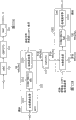
Fig. 8 is calcspar, the feedback-type noise canceling system of expression first work example according to the present invention;
Fig. 9 A and 9B are calcspars, are illustrated respectively in the FF filter circuit that represents among Fig. 8 and the details of FB filter circuit;
Figure 10 is the figure that shows the general difference between the attenuation characteristic of type feedback and feed-forward type noise canceling system;
Figure 11 is the figure that shows the attenuation characteristic of the twin type noise canceling system with the structure that represents in Fig. 8;
Figure 12 is calcspar, the feedback-type noise canceling system of expression second work example according to the present invention;
Figure 13 and 14 is calcspar, the feedback-type noise canceling system of expression the 3rd work example according to the present invention; And
Figure 15 A and 15B are calcspars, represent the structure of FB filter circuit, and represent especially the structure of ADC and DAC.
Embodiment
Noise canceling system
Initiatively reduce the system of external noise, namely noise canceling system begins to popularize in headphone and earplug.The nearly all noise canceling system that puts goods on the market is all formed by analog circuit, and is categorized into roughly feed-forward type and feedback-type according to noise cancellation technique.
Before describing the preferred embodiments of the present invention, with reference to Figure 1A to 5 structure of feedback-type noise canceling system and example and the structure of feed-forward type noise canceling system and the example of operating principle of operating principle are described.
The noise canceling system of feedback-type
The noise canceling system of feedback-type at first, is described.Figure 1A represents the structure for the R channel side, and wherein the feedback-type noise canceling system appends on user's the head its applicable head ear-phone system, in other words, appends on user's head H D.Simultaneously, Figure 1B represents the ordinary construction of feedback-type noise canceling system.
In the occasion of using reponse system, usually microphone 111 is inner as be positioned at headphone housing (housing parts) HP seeing among Figure 1A.Out-of-phase component (noise reduces signal) for the signal (noise signal) of being collected by microphone 111 is fed, and is used for SERVO CONTROL to reduce to enter from the outside noise of headphone housing HP.In this example, the position of microphone 111 becomes elimination point or the control point CP corresponding with the position of user's ear.Therefore, microphone 111 usually is placed on the position near user's ear, in other words, considers that noise reduces on the front front of barrier film that effect is placed on equalizer 16.
The noise canceling system of feedback-type is more specifically described with reference to Figure 1B.The feedback-type noise canceling system that represents in Figure 1B comprises microphone and microphone amplifier section 11, and this microphone and microphone amplifier section 11 comprise microphone 111 and amplifier of microphone 112.Noise canceling system also is included as filter circuit (hereinafter being called the FB filter circuit) 12, composite part 13, the power amplifier 14 of Feedback Control Design, the driver 15 that comprises drive circuit 151 and loud speaker 152, and equalizer 16.
Character A, the D that describes in the square that in Figure 1B, represents, M and-β represents respectively power amplifier 14, driver 15, microphone and microphone amplifier section 11, and the transfer function of FB filter circuit 12.Similarly, character E in the square of equalizer 16 represents the transfer function of equalizer 16 of the signal S of sense of hearing object be multiply by, and the transfer function in driver 15 and the character H representative of eliminating the square of placing between the some CP 111 the space from driver 15 to microphone, in other words driver with eliminate between transfer function.The transfer function of mentioning represents with complex expression.
With reference to Figure 1A and 1B, character N represents the noise that enters to the part around the position of the microphone among headphone housing HP from the noise source NS of outside, and acoustic pressure or the output sound of user's ear are come in character P representative.The reason that noise N enters among the headphone housing HP is, for example as acoustic pressure from the sound of the clearance leakage of the ear pad of wearing earphone case HP or be transferred to the sound of enclosure interior as the result of its vibration that is caused by the such acoustic pressure that is applied on the headphone housing HP.
At this moment, the acoustic pressure P that comes the user's ear in Figure 1B can be expressed by the expression formula in Fig. 3 (1).If note the noise N in the expression formula (1) in Fig. 3, can recognize that then noise N decays to 1/ (1+ADHM β).For the system of the expression formula (1) that makes Fig. 3 as the stably operation in noise reduces the object frequency band of noise eliminating machine, must satisfy the expression formula (2) in Fig. 3.
Usually, because the absolute value of the product of transfer function in the feedback-type noise canceling system is higher than 1 (1<<ADHM β), so explain with the judgement of the Nyquist in the Classical control theory (Nyquist) stability as follows according to the Systems balanth performance of the expression formula (2) of Fig. 3.
" open loop " that consideration produces when locating to cut off when the place (ADHM β) of the loop relevant with noise N in Figure 1B.For example, if cut-off parts is provided between microphone and microphone amplifier section 11 and the FB filter circuit 12, can form " open loop " so.This open loop for example has the such specific character by a kind of like this plate figure representative of seeing in Fig. 4.
Be chosen as the occasion of object in this open loop, by the determination of stability of Nyquist, two conditions are: (1) when phase place during by 0 degree point, gain must be lower than 0dB (0 decibel); (2) when gain is higher than 0 dB, phase place must not comprise 0 degree point.
If any of above condition (1) and (2) do not satisfy, positive feedback is applied on the loop so, causes the vibration (whistle) of loop.In Fig. 4, Reference numeral Pa and Pb represent respectively phase margin, and Ga and Gb represent respectively gain margin.In the less occasion of such allowance, the dispersiveness when installing according to the individual difference in the user of the headphone that utilizes noise canceling system to use with according to headphone, the possibility of vibration is higher.
Specifically, axis of abscissas in Fig. 4 indication frequency, and axis of ordinates half one and Lower Half place indicate respectively gain and phase place thereon.So, when phase place by 0 when point degree, as by seeing that at the gain margin Ga among Fig. 4 and Gb like that, if gain is lower than 0 dB, positive feedback is applied on the loop so, causes vibrating.Yet when gain was equal to or higher than 0 dB, unless phase place does not comprise 0 degree point, otherwise positive feedback was applied on the loop, causes vibration, as from the phase margin Pa Fig. 4 and Pb see.
Now, except above-mentioned noise reduces the function, the reproduction from the necessary sound of the headphone that wherein is incorporated in the feedback-type noise canceling system that represents among Figure 1B is described.Sound import S in Figure 1B is the general term by the voice signal of the original reproduction of driver of headphone, as for example from music again music signal, the sound (wherein headphone plays hearing-aid function) of microphone outside housing or the voice signal (wherein headphone is as headphones) of the communication by such as telephone communication of equipment.
If note the sound import S in the expression formula (1) in Fig. 3, then the transfer function E of equalizer 16 can be represented by the expression formula in Fig. 3 (3).And if also consider the transfer function E of equalizer 16 in the expression formula (3) at Fig. 3, then the acoustic pressure P of the noise canceling system of Figure 1B can be represented by the expression formula in Fig. 3 (4).
If the position of supposition microphone 111 is very near the position of ear, so because the transfer function of character H representative (ear) 111 from driver 15 to microphone, and character A and D represent respectively the transfer function of power amplifier 14 and driver 15, so can recognize, obtain the characteristic similar with not having the characteristic of common headphone that noise reduces function.The transfer function E that is noted that equalizer 16 in this example is equivalent in fact the open loop characteristic of seeing on frequency axis.
The noise canceling system of feed-forward type
The noise canceling system of feed-forward type is described now.Fig. 2 A represents the structure for the R channel side, and wherein the head ear-phone system of feed-forward type noise canceling system application appends on user's head, in other words, appends on user's head H D.Simultaneously, Fig. 2 B represents the ordinary construction of feed-forward type noise canceling system.
In the feed-forward type noise canceling system, microphone 211 is as basically being arranged in outside the headphone HP seeing among Fig. 2 A.So, the noise of being collected by microphone 211 stands suitable filtering, and is then reproduced by the driver 25 that provides in headphone housing HP, thereby eliminates noise at the place, place near ear.
The noise canceling system of feed-forward type is more specifically described with reference to Fig. 2 B.The feed-forward type noise canceling system that represents in Fig. 2 B comprises microphone and microphone amplifier section 21, and this microphone and microphone amplifier section 21 comprise microphone 211 and amplifier of microphone 212.Noise canceling system also is included as filter circuit (hereinafter being called the FF filter circuit) 22, composite part 23, the power amplifier 24 of feedfoward control design and comprises drive circuit 251 and the driver 25 of loud speaker 252.
In the feed-forward type noise canceling system that also in Fig. 2 B, represents, character A, the D that in square, describes, and M represent respectively power amplifier 24, driver 25, and the transfer function of microphone and microphone amplifier section 21.And in Fig. 2, character N represents external noise source.The main cause that noise enters headphone housing HP from noise source N contacts as described in the feedback-type noise canceling system as mentioned.
And, in Fig. 2 B, from the position of external noise N to the transfer function of eliminating some CP, in other words, in noise source and the transfer function of eliminating between putting, represented by character F.And, 211 the transfer function from noise source N to microphone, in other words, the transfer function between noise source and microphone is by character F ' representative.In addition, from driver 25 to the transfer function of eliminating point (ear location) CP, in other words, the transfer function between driver and elimination point is represented by character H.
So, if the FF filter circuit 22 of core that forms the feed-forward type noise canceling system by-α representative, the acoustic pressure or the output sound P that come so the user's ear in Fig. 2 B can be represented by the expression formula in Fig. 5 (1).
Here, if consider ideal conditions, the transfer function F between noise source and elimination point is represented by the expression formula in Fig. 5 (2) so.Then, if the expression formula in Fig. 5 (2) is updated in the expression formula (1) in Fig. 5, the acoustic pressure P in the feed-forward type noise canceling system that represents in Fig. 2 B cancels out each other owing to first and second so, so can be represented by the expression formula in Fig. 5 (3).By expression formula (3), can recognize that noise is eliminated, only have simultaneously the reservations such as the music signal that will listen or object voice signal, and can enjoy and the similar sound of acoustic phase in common headphone operation.
Yet, in fact, be difficult to obtain having the structure of the complete filter of the such transfer function that satisfies the expression formula (2) that in Fig. 5, shows fully.Specifically, in intermediate frequency and high frequency region, usually not carrying out above-mentioned a kind of like this active noise reduces to process, intercept and capture but usually use by the passive sound of headphone, this is owing to such reason: individual difference is huge, because the shape of ear is different in different people, and the additivity of headphone is different in different people; And characteristic is according to the position of the position of noise and microphone and become.Be noted that the expression formula (2) in Fig. 5, as obvious by expression formula itself, mean that the transfer function from the noise source to the ear location can be by the breadboardin that comprises transfer function α.
Be noted that from different in the feedback-type noise canceling system, at the elimination point CP in the feed-forward type noise canceling system that represents among Fig. 2 A and the 2B as seeing among Fig. 2 A, being set to any ear location of user.Yet under general case, transfer function α was fixed in the past and was defined as aiming at a certain target property in the design phase.Therefore, the possibility that has a kind of like this phenomenon to occur: because ear shape is different in different user, so can not realize enough noise eradicating efficacies, perhaps adds noise component(s) but be not in the opposite phase, cause the generation of abnormal sound.
By these, the noise canceling system of feedback-type and feed-forward type generally has different characteristics, because although the possibility of feed-forward type noise canceling system vibration is low and therefore stability is higher, but be difficult to obtain enough attenuations, and the feed-forward type noise canceling system may require the attention for the stability of a system, can expect huge attenuation simultaneously.
Propose independently a kind of noise of Adaptive Signal Processing technology that uses and reduce headphone.Reduce in the situation of headphone at the noise that uses the Adaptive Signal Processing technology, microphone is provided at inside and the outside of headphone housing.Internal microphone is used for analyzing for the error signal that offsets with the filter process component, and produces and upgrade new sef-adapting filter.Yet, because the noise outside the headphone housing is basically by digital filter processing and reproduced, so noise reduces the form that headphone generally has feedforward system.
Noise canceling system according to the embodiment of the invention
Noise canceling system according to the embodiment of the invention has above-mentioned reponse system and the advantage of feedforward system.
In the embodiment of the invention that is described below, the FF filter circuit 22 in the feed-forward type noise canceling system and the FB filter circuit 12 in the feedback-type noise canceling system both have the structure of digital filter.FF filter circuit 22 has transfer function-α, and therefore hereinafter sometimes is called the α circuit.Simultaneously, FB filter circuit 12 has another transfer function-β, and therefore hereinafter sometimes is called beta circuit.
Fig. 6 A, 6B and 6C are calcspars, represent that respectively FF filter 22, FB filter 12 and each are configured to the FF of digital filter and the example of FB filter circuit 22 and 12.At the feed-forward type noise canceling system that represents among Fig. 6 A as seeing among Fig. 2, being inserted between amplifier of microphone 212 and the power amplifier 24.Simultaneously, at the feedback-type noise canceling system that represents among Fig. 6 B as seeing among Fig. 1, being inserted between amplifier of microphone 112 and the power amplifier 14.
Be configured to the occasion of digital filtering in any of FF filter circuit 22 and FB filter circuit 12, it by be used for the analogue noise signal of being collected by microphone convert to the digital noise signal ADC (analog to digital converter), be used for carrying out arithmetical operation and reduce the DSP/CPU (digital signal processor/CPU) of signal and be used for that the digital noise from DSP/CPU is reduced signal to convert the DAC (digital to analog converter) that analogue noise reduces signal to and form from the noise that the digital noise signal deducts noise forming.Be noted that the expression DSP/CPU in Fig. 6 C means one that uses DSP and CPU.
Be configured to by this way the occasion of digital filtering at FF filter circuit 22 or FB filter circuit 12, (1) system allows the automatic selection in a plurality of patterns or passes through user's manual selection, and this improves serviceability as seeing from the user, (2) owing to allow the digital filtering of meticulous control, so can realize presenting minimum dispersed high accuracy control quality, this causes noise decrease and noise to reduce the increase of frequency band.
And, (3) because filter shape need not change the quantity of part by changing for the modification for the software of arithmetical operation processing unit (digital signal processor (DSP)/CPU (CPU)), so be conducive to the change that in the variation of system or equipment energy characteristic, relates to.(4) because identical ADC and/DAC and DSP/CPU also be used for the outside input such as reproducing music or telephone relation, so can expect that by also use high-precision digital equalising for such external input signal the high sound quality reproduces.
If FF filter circuit 22 or FB filter circuit 12 form with digitized forms by this way, control becomes possiblely for various situations so flexibly, and can construct and a kind ofly can eliminate noise and the system that has nothing to do with the user of the system of use with high-quality.
The problem of feed-forward type noise canceling system
The feedforward system remarkable advantage that has like that high stability described above.Yet it has intrinsic problem.Fig. 7 A and 7B show the problem of feedforward system, and are illustrated in the structure of the feedforward system on the R channel side, and wherein the head ear-phone system of feed-forward type noise canceling system application appends on user's head H D of user or audience.
With reference to Fig. 7 A, represented by F1 to the transfer function of eliminating some CP from the noise source N1 that is defined as starting point, this elimination point CP is the impact point of noise cancellation, and be provided at duct on the headphone housing inboard near.The transfer function of the microphone 211 that provides to the outside at the headphone housing from noise source N1 simultaneously, is by F1 ' representative.
At this moment, the sound that the microphone 211 that is provided by the outside at the headphone housing is collected is used for regulating the filter of FF filter circuit (α circuit) 22.Then, simulate such as usefulness (F1 ' ADHM α) by expression in the expression formula among Fig. 5 (3) to the transfer function F1 that eliminates some CP, and deducted in the last acoustic space of sound in headphone inside, cause reducing of noise.Here, the expression formula in Fig. 5 (3) is applied to low frequency range usually, and phase place is moved at high frequency region.Therefore, usually do not take the gain of FF filter circuit 22, in other words, do not offset.
Here, if the filter of supposition FF filter circuit 22 is fixed, and transmission characteristic α is as optimised in a kind of like this noise position relationship seeing among Fig. 7 A, the position that is used for simultaneously collecting the microphone of noise is fixed and in addition uses single microphone, so as not being preferred by noise source FF filter circuit 22 under such a case that the opposite side for microphone 211 exists the indication of the noise source N2 among Fig. 7 B.
Specifically, in the situation of the example that in Fig. 7 B, shows, at first leak into the headphone housing from the sound wave of the noise of noise source N2 emission by the gap between headphone and user's head, and be formed on the disagreeable noise in the headphone housing.After this, sound wave is come the outside of headphone, and is collected by microphone 211, and afterwards, they stand (α), and by driver to reproduce by the specific filtering of FF filter circuit 22.
As can being recognized by the comparison between Fig. 7 B and 7A, in the situation of the layout of Fig. 7 A, the noise that bleeds and arrive simultaneously from the reproducing signal that driver 25 reproduces and to eliminate a some CP.Therefore, it is wider that the phase place of noise and reproducing signal becomes reciprocal frequency band within it, and therefore, realize that fixing noise reduces effect.Yet in the situation of the layout of Fig. 7 B, the noise that leaks into the noise of headphone enclosure interior and arrive microphone 211 exists, and as a result of, having not between it, poor signal of expected time adds each other.Thereby in intermediate frequency and high frequency region, it is not opposite each other that the phase place of noise and reproducing signal becomes particularly, but the frequency band that phase place is added within it as positive phase increases.
Correspondingly, under the state that shows in Fig. 6 B, although arrange that being intended for use noise reduces, noise increases under the frequency that phase place does not overlap each other.At this moment, even in the broadband district, can realize huge decay, because human auditory's sensation has unfamiliar sensation for noise even the fact that produces in narrow-band.Therefore, the layout that represents in Fig. 6 B is not-so-practical.
Naturally, this makes this situation seem more possible when frequency increases to the high frequency region that wherein phase rotated is higher.Correspondingly, this forms the reason that effective effect frequency band that noise is eliminated (in other words the gain of α characteristic exist frequency band) narrows down within it in the FF of feed-forward type noise canceling system filter circuit 22.
The noise canceling system that the embodiment of the invention is used
Therefore, the noise canceling system that the embodiment of the invention is used has a kind of essential structure, and wherein feedback-type noise canceling system and feed-forward type noise canceling system superpose each other, to form single noise canceling system.
Specifically, in the noise canceling system of the present embodiment that is described below, when it is in such as a kind of state seeing among Fig. 7 A, on broadband, stably carries out noise by the feed-forward type noise canceling system and eliminate.On the other hand, when the noise canceling system of present embodiment was in such as a kind of state seeing among Fig. 7 B, the noise that leaks in the headphone housing also can be eliminated effectively by the feedback-type noise canceling system.
The first work example of noise canceling system
The first work example of the noise canceling system that the present invention is suitable for is illustrated among Fig. 8.Simultaneously, the FF filter circuit 22 that represents in Fig. 8 and FB filter circuit 12 are illustrated among Fig. 9 A and Fig. 9 B particularly.At first with reference to Fig. 8, the noise canceling system of expression is included in the feedback-type noise canceling system that the right part office of Fig. 8 represents and the feed-forward type noise canceling system that represents in the left part office of Fig. 8.
More particularly, the feedback-type noise canceling system in the noise canceling system that represents in Fig. 8 comprises: microphone and microphone amplifier section 21, and it comprises again microphone 211 and amplifier of microphone 212; FF filter circuit (α circuit) 22; Power amplifier 24; And driver 25.FF filter circuit 22 is as having the structure of the digital filter that is formed by ADC 221, DSP/CPU part 222 and DAC 223 seeing among Fig. 9 A.
Note, in the feed-forward type noise canceling system part that in Fig. 8, represents, the transfer function of microphone and microphone amplifier section 21 is represented by " M1 ", the transfer function of FF filter circuit 22 is represented by " α ", the transfer function of power amplifier 24 is by " A1 " representative, and the transfer function of driver 25 is represented by " D1 ".And, in feed-forward type noise canceling system part, can consider driver with eliminate transfer function " H1 " between the point, noise source with eliminate between transfer function " F ", reach the transfer function " F ' " between noise source and microphone.
Simultaneously, the feedback-type noise canceling system that represents in Fig. 8 partly comprises: microphone and microphone amplifier section 11, and it comprises again microphone 111 and amplifier of microphone 112; FB filter circuit (beta circuit) 12; Power amplifier 14; And driver 15, it comprises again drive circuit 151 and loud speaker 152.FB filter circuit 12 is as having the structure of the digital filter that comprises ADC 121, DSP/CPU part 122 and DAC 123 seeing among Fig. 9 B.
Note, in the feedback-type noise canceling system part that in Fig. 8, represents, the transfer function of microphone and microphone amplifier section 11 is represented by " M2 ", the transfer function of FB filter circuit 12 is represented by " β ", the transfer function of power amplifier 14 is by " A2 " representative, and the transfer function of driver 15 is represented by " D2 ".And, in feedback-type noise canceling system part, can consider the transfer function " H2 " between driver and elimination point.
In the noise canceling system of the structure that represents in Fig. 8, external noise is by feed-forward type noise canceling system extracting section and elimination.Yet, the character of the sound source by noise and the sound wave of sound source (for example, the behavior of the sound wave of behavior by picture spherical wave or plane wave and so on), although obtain as described above the frequency band that noise reduces in the headphone housing within it, but in fact be difficult to eliminate efficiently noise, and as a result of, noise residue frequency band within it may appear.Similar Problems is also by the shape of the additivity of headphone or individual ear and occur.
Yet, in the situation of the noise canceling system with the structure that represents in Fig. 8, remaining noise component(s) can be eliminated by the effect of feedback-type noise canceling system part efficiently with the noise component(s) that enters in the headphone housing in feed-forward type noise canceling system part.In other words, because feedback-type noise canceling system part and feed-forward type noise canceling system can be operated simultaneously, reduce effect so realize high noise eradicating efficacy or the noise of effect that ratio is realized when each of the noise canceling system of independent use feed-forward type and feedback-type.
By this way, in the noise canceling system that in Fig. 8, represents, the noise that leaks in the headphone housing is being eliminated a suitably elimination of the feedback-type noise canceling system that the CP place can be represented by the right part office at Fig. 8 part, and comes the noise of the outer noise source N of comfortable headphone housing partly suitably to eliminate at the feed-forward type noise canceling system that elimination point CP place can be represented by the left part office at Fig. 8.
Be noted that feedback-type noise canceling system part in the noise canceling system that represents and each of feed-forward type noise canceling system comprise microphone and microphone amplifier section, power amplifier and driver independently in Fig. 8.
Figure 10 shows the general difference of attenuation characteristic between feedback-type noise canceling system and feed-forward type noise canceling system.With reference to Figure 10, axis of abscissas indication frequency, and axis of ordinates indication attenuation.And as seeing among Figure 10, although the attenuation characteristic of feedback-type noise canceling system has narrow-band and high-caliber feature, the attenuation characteristic of feed-forward type noise canceling system has broadband and low-level feature, as described above.
Yet the noise canceling system that represents in Fig. 8 thinks that caing be compared to is the noise canceling system of twin type (twintype), and it comprises feed-forward type noise canceling system part and feedback-type noise canceling system.The noise canceling system of twin type has the composite attenuation characteristic that the characteristic that shows by feed-forward type noise canceling system and feedback-type noise canceling system forms in Figure 10.
Figure 11 show twin type noise canceling system wherein have the actual measured value of the attenuation characteristic of the structure that in Fig. 8, represents, wherein use the attenuation characteristic of feedback-type noise canceling system actual measured value, and wherein use the actual measured value of the attenuation characteristic of feed-forward type noise canceling system.
With reference to Figure 11, axis of abscissas indication frequency, and axis of ordinates indication attenuation.And, by thick dashed line indication and have an attenuation characteristic that character " feedback " appends to the curve indication feedback type noise canceling system on it.Simultaneously, by fine dotted line indication and have character " feedforward " and append to the attenuation characteristic that another curve on it is indicated the feed-forward type noise canceling system.By solid line indication and have the other curve indication that character " twin " appends on it and have the attenuation characteristic of the twin type noise canceling system of the structure that in Fig. 8, represents.
As can recognizing from Figure 11, the feedback-type noise canceling system has narrow-band and high-caliber attenuation characteristic, and the feed-forward type noise canceling system has broadband and low-level another kind of attenuation characteristic.And, can recognize that the twin type noise canceling system has at wide frequency ranges and presents high-caliber attenuation characteristic.
By this way, the twin type noise canceling system with the structure that represents in Fig. 8 has both of attenuation characteristic of reponse system and feedforward system, and can realize broadband and high-caliber attenuation characteristic.
The second work example of noise canceling system
Figure 12 represents the second work example of the noise canceling system that the present invention is suitable for.With reference to Figure 12, the second work example of the noise canceling system of expression comprises feed-forward type noise canceling system part, the latter comprises again microphone and microphone amplifier section 21, and this microphone and microphone amplifier section 21 comprise again microphone 211 and amplifier of microphone 212.Feed-forward type noise canceling system part also comprises: FF filter circuit 22, and it is formed by ADC 321, DSP/CPU part 322 and DAC 323; Power amplifier 33; And driver 34, it comprises again drive circuit 341 and loud speaker 342.
The second case of the noise canceling system that represents in Figure 12 also comprises feedback-type noise canceling system part, and the latter comprises again microphone and microphone amplifier section 11, and this microphone and microphone amplifier section 11 comprise again microphone 111 and amplifier of microphone 112.Feedback-type noise canceling system part also comprises: FB filter circuit 12, and it is formed by ADC 324, DSP/CPU part 322 and DAC 323; Power amplifier 33; And driver 34, it is formed by drive circuit 341 and loud speaker 342 again.
Specifically, although have wherein feedback-type noise canceling system part and the feed-forward type noise canceling system forms independently of one another and structure connected to one another according to the noise canceling system of the first work example that in Fig. 8, represents, but the second case of the noise canceling system that represents in Figure 12 is configured to, and feedback-type and feed-forward type noise canceling system use DSP/CPU part 322, DAC 323, power amplifier 33 and driver 34 jointly.
And, in the second case of the noise canceling system that in Figure 12, represents, the transfer function of microphone and microphone amplifier section 21 is represented by " M1 ", the transfer function of FF filter circuit 22 is represented by " α ", the transfer function of power amplifier 33 is by " A " representative, and the transfer function of driver 34 is represented by " D ".And the transfer function of microphone and microphone amplifier section 11 is by " M2 " representative, and the transfer function of FB filter circuit 12 is represented by " β ".
Also in the noise canceling system according to the second work example that in Figure 12, represents, can consider driver with eliminate transfer function " H " between the point, noise source with eliminate between transfer function " F ", reach the transfer function " F " between noise source and microphone.
And in the second work example that also represents in Figure 12, sound import supplies to DSP/CPU part 322 by ADC 35, and it can add noise to and reduces on the signal by this DSP/CPU part 322.
Correspondingly, in the noise canceling system according to the second work example that in Figure 12, represents, DSP/CPU part 322 carry out based on is formed by the sound of collecting at the microphone 211 on the headphone hull outside noise reduce signal processing and based on the sound of being collected by the microphone 111 on headphone housing inboard form processing that another kind reduces signal, and then the synthetic noise that forms like this reduce signal.
By this way, in the situation according to the routine noise canceling system of the second work that in Figure 12, represents, because it is included in those elements that share between feedback-type noise canceling system part and the feed-forward type noise canceling system part, thus the quantity of part can be reduced, but and simplified construction.
And, according to the noise canceling system of twin type, described above like that by making the feed-forward type noise canceling system part that is formed by microphone and microphone amplifier section 21, FF filter circuit 22, power amplifier 33 and driver 34; Work simultaneously with the feedback-type noise canceling system part that is formed by microphone and microphone amplifier section 11, FB filter circuit 12, power amplifier 33 and driver 34, can realize broadband and high-caliber attenuation characteristic.
The 3rd work example of noise canceling system
In passing explanation, in the twin type noise canceling system that in Fig. 8 or 12, represents, hear external source the audience, as from the music signal of music reproduction device or the voice signal collected by the hearing aid microphone, as by sound import S indication, owing to hear such sound or music, so the noise decrease may be very large.On the contrary, although needn't hear external source, sound can reduce to form the silent state of high-quality magnitude.For example, in the occasion that the audience must work under very big noise, strong request is with high-quality magnitude noise decrease.
Therefore, although be the twin type noise canceling system with feedback-type noise canceling system and another feed-forward type noise canceling system according to the noise canceling system of the 3rd work example, its allows the selectivity of noise canceling system part to work.Specifically, in the time will listening external source, one of feedback-type noise canceling system part and feed-forward type noise canceling system part are worked.Yet, in the time of will forming the silent state (minimum sound state) of high-quality magnitude when there is no need to listen external source, feedback-type noise canceling system part and feed-forward type noise canceling system part are all worked.
Figure 13 and 14 represents the noise canceling system of the 3rd work example according to the present invention.The similar essential structure of structure that has the noise canceling system of the second work example that in Figure 12, represents with basis according to the noise canceling system of the 3rd work example that in Figure 13 and 14, represents.Thereby, save here with the 3rd element of working routine noise canceling system that in Figure 13 and 14, represents according to the common basis of the element of the routine noise canceling system of the second work that in Figure 12, represents and describe, to avoid repetition.
Noise canceling system according to the 3rd work example that represents in Figure 13 is configured to, and is included in addition the switching circuit 36 of insertion between microphone and microphone amplifier section 11 and the ADC 324 according to the noise canceling system of the second work example that represents in Figure 12.Therefore, in the noise canceling system according to the 3rd work example that represents in Figure 13, switching circuit 36 is used in wherein voice signal from microphone and microphone amplifier section 11 and supplies to the state of ADC 324 and wherein change between the sound import S as external source of outside supply supplies to the another kind of state of ADC 324.
Correspondingly, in the noise canceling system according to the 3rd work example that in Figure 13, represents, if switching circuit 36 switches to input terminal a side, do not supply with so sound import S, and FB filter circuit 12 and FF filter circuit 22 work, thereby feedback-type noise canceling system part and feed-forward type noise canceling system part all work, to form the silent state of high-quality magnitude.
On the other hand, if switching circuit 36 switches to another input terminal b side, do not supply with so the sound from FF filter circuit 22, and ADC 324, DSP/CPU part 322 and DAC 323 usefulness act on the input circuit " equalizer " of sound import S.Then, in this example, FF filter circuit 22 works, and therefore, only has the feed-forward type noise canceling system partly to work.Therefore, although eliminate noise, the audience can hear sound import S.
Correspondingly, in this example, ADC 321, DSP/CPU part 322 and DAC323 realize the function of FF filter circuit 22, and ADC 324, DSP/CPU part 322 and DAC 323 realizations are used for the function of the equalizer of sound import S.In other words, function and being used for FF filter circuit of DSP/CPU part 322 and DAC 323 is processed the function of the equalizer of sound import S.
Simultaneously, noise canceling system according to the 3rd work example that represents in Figure 14 is configured to, and is included in addition the switching circuit 37 of insertion between microphone and microphone amplifier section 21 and the ADC 321 according to the noise canceling system of the second work example that represents in Figure 12.Therefore, in the noise canceling system according to the 3rd work example that represents in Figure 14, switching circuit 37 is used in wherein voice signal from microphone and microphone amplifier section 21 and supplies to the state of ADC321 and wherein change between the sound import S as external source of outside supply supplies to the another kind of state of ADC321.
Correspondingly, in the noise canceling system of the 3rd work example that in Figure 14, represents, if switching circuit 37 switches to input terminal a side, do not supply with so sound import S, and FF filter circuit 22 and FB filter circuit 12 work, thereby feed-forward type noise canceling system part and feedback-type noise canceling system part all work, to form the silent state of high-quality magnitude.
On the other hand, if switching circuit 37 switches to another input terminal b side, do not supply with so the sound from microphone and microphone amplifier section 21, and ADC 321, DSP/CPU part 322 and DAC 323 usefulness act on the input circuit " equalizer " of sound import S.Then, in this example, FB filter circuit 12 works, and therefore, only has the feedback-type noise canceling system partly to work.Therefore, although eliminate noise, the audience can hear sound import S.
Correspondingly, in this example, ADC 324, DSP/CPU part 322 and DAC323 realize the function of FB filter circuit 12, and ADC 321, DSP/CPU part 322 and DAC 323 realizations are used for the function of the equalizer of sound import S.In other words, function and being used for FB filter circuit of DSP/CPU part 322 and DAC 323 is processed the function of the equalizer of sound import S.
By this way, in the noise canceling system according to above the 3rd work example of describing with reference to Figure 13 and 14, occasion at the sound import S that will listen external source, one of feed-forward type noise canceling system part and feedback-type noise canceling system part are worked, although thereby eliminating or noise decrease, the audience can successfully hear sound import.
And, want to listen under a kind of like this situation of silent state the audience, feed-forward type noise canceling system part and feedback-type noise canceling system part all are used for eliminating the noise of the noise that comes from the outside and self generation of not conformed to by phase place to form the silent state of high-quality magnitude.Therefore, the audience is affable from experiencing the sensation that very noisy reduces effect.
Be noted that the noise canceling system according to the 3rd work example that represents is configured to, and when sound import S will reproduce, only has the feed-forward type noise canceling system partly to work in Figure 13; And be configured to according to the noise canceling system of the 3rd example that in Figure 14, represents, only have the feedback-type noise canceling system partly to work.Yet, conversion between the noise canceling system part is not limited to this, but otherwise might be configured to noise canceling system, the audience can be that feed-forward type noise canceling system part should work or feedback-type noise canceling system part is changed between should working.
Specifically, might make up the noise canceling system according to the 3rd work example that in Figure 13 and 14, represents, thereby switching circuit 36 and switching circuit 37 are provided.And, switching circuit 38 is provided, being used at sound import S is supply to switching circuit 36 or supply to conversion between the switching circuit 37.
Then, if the switching circuit that newly provides 38 switches to sound import S and supplies to switching circuit 36, switching circuit 36 switches to input terminal b side and switching circuit 37 switches to input terminal a side so, in order to the feed-forward type noise canceling system is worked, thereby the audience can hear sound import S.
On the contrary, if the switching circuit that newly provides 38 switches to sound import S and supplies to switching circuit 37, switching circuit 37 switches to input terminal b side and switching circuit 36 switches to input terminal a side so, in order to the feedback-type noise canceling system is worked, thereby the audience can hear sound import S.
Nature, also in this example, when the audience wanted to form the silent state of high-quality magnitude, switching circuit 36 and switching circuit 37 all switched to input terminal a side.Therefore, feedback-type noise canceling system part and feed-forward type noise canceling system part all work, to form the silent state of high-quality magnitude.
Be noted that switching circuit 36 described above, 37 and 38 any can form mechanical switch, or form electric switch.
And, although described above be that the noise canceling system of expression in Fig. 8,12,13 and 14 can be accepted the supply of external source sound import S, they are not limited to those of the type just described.Also might form the noise canceling system that reproduces as the noise that only is used for not having accepting from the outside importation of sound import S and any of the noise canceling system of describing.
The object lesson that the digitlization of FB filter circuit 12 and FF filter circuit 22 forms
In the occasion that FB filter circuit 12 and FF filter circuit 22 form with digitized forms, they each is formed by ADC, DSP/CPU part and DAC as described in reference Fig. 6 C and 9.In this example, if for example be that translation type and the ADC that can carry out high-speed transitions of order and DAC are used for ADC and DAC, noise reduces signal and can produce in suitable timing place so, realize thus reducing of noise.
Yet ADC and the DAC that can carry out the order conversion hysteria of high-speed transitions are costlinesses like this, thereby need expensive for FB filter circuit 12 and FF filter circuit 22.Therefore, describe a kind of even occasion of using in the past the ADC of ∑-Δ (sigma-delta) type or DAC and also might produce that noise reduces signal and the technology that do not produce huge retardation in suitable timing place.Be noted that for simplified characterization the situation that this technology wherein is applied to FB filter circuit 12 is used as example, provides following description.Yet this technology also can be applied to FF filter circuit 22 similarly.
Figure 15 A and 15B represent the structure of FB filter circuit 12, particularly the structure of ADC 121 and DAC 123.As seeing among Fig. 6 C and the 15A, FB filter circuit 12 comprises ADC 121, DSP/CPU part 122 and DAC 123.As seeing among Figure 15 B, ADC 121 comprises anti-alias filter 1211, ∑-Δ ADC part (sigma-delta) 1212, reaches decimation filter 1213.Simultaneously, DAC 123 comprises interpolation filter 1231, ∑-Δ DAC part (sigma-delta) 1232, reaches low pass filter 1233.
Usually, ADC 121 and DAC 123 use excessively sampling method and the ∑-Δ modulation of wherein using 1 signal.For example, stand the occasion of digital signal processes in analog signal by DSP/CPU part 122, it converts 1 Fs/ multidigit (in most of the cases, 6 to 24) to.Yet, according to ∑-Δ method, sampling frequency Fs[Hz] in most of the cases be elevated to M MFs[Hz doubly], to carry out sampling.
As seeing among Figure 15 B, prevent from being higher than the signal input and output in the frequency band of 1/2 sampling frequency Fs at anti-alias filter 1211 that the import department of ADC 121 provides and the low pass filter 1233 that provides in the export department office of DAC 123.Yet, in fact, because anti-alias filter 1211 and low pass filter 1233 all form by analog filter, so be difficult to obtain near attenuation characteristic precipitous Fs/2.
As seeing among Figure 15 B, decimation filter 1213 is included in the ADC side, and interpolation filter 1231 is included in the DAC side, and these filters are used for carrying out selection process and interpolation process.Simultaneously, the precipitous digital filter of high exponent number is used for applying the band limit in each inside of filter, reduces thus the burden on the anti-alias filter 1211 of accepting analog signal and the also low pass filter 1233 at outputting analog signal.
In passing explanation, the delay that occurs in ADC 121 and DAC 123 is almost produced by the high-order digit filter in decimation filter 1213 and interpolation filter 1231.Specifically, owing to have the filter of high exponent number (in the situation of finite impulse response (FIR) (FIR) filter, filter with huge minute tap number) is used in the district of the sampling frequency with MFs Hz in order to around Fs/2, obtain precipitous characteristic, so final generation group postpones.
In this digital filter part, for fear of the harmful effect that the time waveform by phase distortion degenerates, use the FIR filter with linear phase characteristic.Particularly, have the based on motion average filter to wish to use the trend of FIR filter, (sin (x)/x) can realize interpolation characteristic to this motion average filter by the SINC function.Be noted that in the situation of the filter of linear phase type half time of filter length almost forms retardation.
The FIR filter can represent that its steepness and attenuating increase with exponent number (tap number) and the natural characteristic of increase.Owing to getting, the filter normal operation with little exponent number not very many, larger because it does not provide significant attenuation (many leakages are provided) and affected by alias.Yet the occasion of the filter of the little exponent number of use can reduce time of delay in the feedback-type noise canceling system, becomes possible because satisfy the use of the FIR filter of condition described below.
If reduce time of delay, phase rotated reduces so.As a result, when FB filter circuit 12 was designed to produce as mentioned such compound open loop characteristic of describing with reference to Fig. 4, the band that its characteristic is higher than 0 dB can enlarge, and can realize remarkable result by noise canceling system aspect frequency band and its attenuation characteristic.In addition, the degree of freedom that can easily imagine when filter is produced also increases.
Thereby, in Figure 15 B, all be the decimation filter 1213 of digital filter form and the FIR filter of interpolation filter 1231 for forming, (1) should use the FIR filter that presents the decay that is equal to or greater than-60 dB at the frequency band from approximate (Fs-4kHz) to (Fs+4kHz), wherein Fs is sampling frequency.
In this example, (2) should use the sampling frequency Fs that is equal to or greater than twice (approximate 40kHz) range of audibility, and (3) are used as conversion method to ∑-Δ (sigma-delta) method.And, (4) should permit with the relevant alias leakage component of other frequency band except the frequency band of regulation in condition (1), thereby should use the group delay that produces in its processing mechanism in conversion processing apparatus to be suppressed to the digital filter that is equal to or less than 1ms.
Be used for decimation filter 1213 and interpolation filter 1231 if satisfy the FIR filter of above-mentioned condition (1) and (4), and sampling frequency Fs satisfy condition (2) simultaneously conversion method satisfy condition (3), ADC or the DAC of the ∑ that uses so in the past-Δ type are used for building the FB filter circuit 12 of digitized forms.
Be noted that the detailed basic principle that wherein satisfies the digital filter that forming of above-mentioned condition (1) and (4) do not produce huge delay is described in detail in common Japanese patent application No.2006-301211 co-pending by the present inventor.
Sum up
(1) because as in the noise canceling system of describing above with reference to Fig. 8, one or more microphone mechanism is provided on each of the inboard of headphone housing and the outside, and the signal of being collected by the microphone that the outside at the headphone housing provides is reproduced by specific filter by the driver on the inboard of headphone, so reduce to leak into the noise in the headphone.Simultaneously, owing to reproduced by specific filter by the driver on the inboard of headphone housing by the signal of collecting at the microphone on the inboard of headphone housing, so on broad frequency band, can be carried out reducing than the noise of high attenuation effect amount by noise canceling system.
(2) because as in the noise canceling system of describing above with reference to Figure 12, more than the filtering signal of the inboard microphone in (1), described and the filtering signal of outside microphone mixed by analog or digital mechanism, so the quantity of driver can be reduced to one.
(3) as described in Fig. 6 C, 9 and 15, the filter segment of implementing as FB filter circuit or FF filter circuit is by providing one or more ADC and one or more DAC to be configured to digital filter in system, in order to carry out digital filtering by means of the arithmetic operating apparatus that is formed by DSP or CPU.
(4) as in the situation of the noise canceling system of describing above with reference to Figure 13 and 14, system can be constructed with: first mode, wherein the output signal at the microphone on the inboard of headphone housing and the microphone on its outside all enters ADC, and they are by digital processing whereby; With the second pattern, wherein sending simultaneously instruction to the DSP/CPU part with when the program of being carried out by noise reduction system is transformed into the equalizer program, the input of the microphone signal of the microphone on one of interior and outside of next comfortable headphone housing is switched to external signal (music signal or telephone conversation signal), and is connected on the identical ADC.
In this example, if use first mode, can form so the silent state of high-quality magnitude, if but use the second pattern, can make so feedback-type noise canceling system part and feed-forward type noise canceling system partly only one work, thereby in reproduction noise, reproduce the sound import of external source in order to enjoyed by the audience.And, by first mode and the second pattern are provided, can suppress the quantity of ADC.
The method according to this invention
The first method of the present invention is as mentioned with reference to as described in Fig. 8, can realize by the first that realizes the feedback-type noise canceling system and the second portion of realizing the feed-forward type noise canceling system are worked simultaneously, thereby carry out simultaneously the noise elimination by feedforward system and by reponse system.
On the other hand, jointly used by FB filter circuit 12 and FF filter circuit 22 by such DSP/CPU part 322 and DAC 323 of allowing described above, thereby form and be synthesized by DSP/CPU part 322 with reference to noise reproducing signal as described in Figure 12 as mentioned, can realize using second method according to the embodiment of the invention of single power amplifier 33 and single driver 34.
And by being formed FB filter circuit 12 and FF filter circuit 22 by ADC, DSP/CPU and DAC in order to allow such process: mould/number conversion → noise reduces signal and produces processing → D/A switch, can realize the third method according to the embodiment of the invention.
And, by as can be seen from fig. 12 allow FB filter circuit 12 and FF filter circuit 22 jointly to be used by DSP/CPU part 322 and DAC 323, in other words, reduce signal and can be synthesized thereby reduce the signal noise by the noise that the noise that makes DSP/CPU part 322 be formed for reponse system reduces signal and further is formed for feedforward system, can realize the cubic method according to the embodiment of the invention.
And, by as seeing in Figure 13 and 14, carry out about the sound collected by microphone and sound import S which should be processed conversion, can realize the 5th method according to the embodiment of the invention.
Other
Note, in above-described embodiment, feedback-type noise canceling system part mainly the function by microphone 111 being realized divide as the first sound collection unit, by make FB filter circuit 12 realize as the first signal processing section function, realize as the function of the first amplifier section and the function by the driver 15 that comprises loud speaker 152 is realized as the first sound radiating portion by making power amplifier 14, and form.
Simultaneously, feed-forward type noise canceling system part mainly the function by microphone 211 being realized divide as the second sound collection unit, by make FF filter circuit 22 realize as the secondary signal processing section function, realize as the function of the second amplifier section and the function by the driver 25 that comprises loud speaker 252 is realized as the second sound radiating portion by making power amplifier 24, and form.
And, the function that FB filter circuit 12 and FF filter circuit 22 are realized as composite part.Similarly, as seeing among Figure 12, being that the DSP/CPU of common elements has and forms noise for reponse system and feedforward system and reduce the function of signal for FB filter circuit 12 and FF filter circuit 22, and has the function that the synthetic noise that so forms reduces signal.
Then, power amplifier 33 in Figure 12 is realized as the function that is used for amplifying by the single amplifier section of the synthetic single signal of composite part, and driver 34 is realized as being used for responding the function of launching the single sound radiating portion of sound by single amplifier section amplifying signal.And the switching circuit 36 that represents in Figure 13 and the switching circuit that represents in Figure 14 37 realized as being used for the function of conversion portion of converted output signal.
And although in above-described embodiment, FB filter circuit 12 and FF filter circuit 22 all have the structure of digital filter, and according to embodiments of the invention, the structure of FB filter circuit 12 and FF filter circuit 22 is not limited to this.Have the occasion of the structure of analog filter at FB filter circuit 12 and FF filter circuit 22, also can realize and above-mentioned those similar effects.
And although in above-described embodiment, sound import S is accepted as external source, and the function of accepting external source needn't be provided.Specifically, can form can a noise decrease and there is no need to accept the noise reduction system of the external source such as music for noise canceling system.
And although in above-described embodiment, the present invention is applied to head ear-phone system for simplified characterization, and all systems needn't be incorporated in the headphone body.For example, also possiblely be, provide discretely processing mechanism such as FB filter circuit, FF filter circuit and power amplifier as the box on the outside, perhaps combined from different equipment them.Here, but different equipment can be various types of hardware of producing sound or music signal, such as portability audio frequency player, telephone plant and network sound communication equipment.
Specifically, be applied to the portability telephone set and be connected to the occasion of the headphones on the portability telephone set in the present invention, for example, even externally in the noise circumstance, also can be expected at the telephone relation under the good condition.In this case, if FF filter circuit, FB filter circuit, drive circuit etc. are provided at portability telephone terminal side, can simplify so the structure of headphone side.Nature also might provide all elements in the headphone side, supplies with thereby it receives from the sound of portability telephone terminal.
Although use particular term to describe the preferred embodiments of the present invention, such description is only for illustration purpose, and is appreciated that and can changes and change and do not break away from the spirit or scope of following claims.
Claims (13)
1. noise canceling system comprises:
The first sound collection unit is divided, and is provided on the housing on the user ear to be appended to, and is configured to collect noise and output the first noise signal;
The first signal processing section is configured to produce first noise that is used for reducing at a predetermined elimination noise of locating based on the first noise signal and reduces signal;
The audio emission part divides with respect to described the first sound collection unit to be provided at audio emission direction side, and is configured to reduce the signal shot noise based on the first noise and reduces sound;
The second sound collection unit is divided, and partly is provided at the audio emission direction side of the described housing on the user ear to be appended to respect to described audio emission, and is configured to collect noise and output the second noise signal; And
The secondary signal processing section is configured to produce the second noise that is used for reducing at the noise of eliminating the some place based on the second noise signal and reduces signal;
Described audio emission part reduces the signal shot noise based on the first and second noises and reduces sound.
2. noise canceling system according to claim 1 also comprises being configured to the composite part that synthetic the first and second noises reduce signal, and wherein, described audio emission part reduces the signal shot noise based on synthetic noise and reduces sound.
3. noise canceling system according to claim 1, wherein, described first signal processing section is to comprise following digital filter circuit:
The first mould/number conversion part is configured to the first noise signal is converted to the first digital noise signal;
The first processing section is configured to produce the first digital noise based on the first digital noise signal and reduces signal; And
The first D/A switch part is configured to that the first digital noise is reduced signal and converts analogue noise to and reduce signal.
4. noise canceling system according to claim 1, wherein, described secondary signal processing section is to comprise following digital filter circuit:
The second mould/number conversion part is configured to the second noise signal is converted to the second digital noise signal;
The second processing section is configured to produce the second digital noise based on the second digital noise signal and reduces signal; And
The second D/A switch part is configured to that the second digital noise is reduced signal and converts analogue noise to and reduce signal.
5. noise canceling system according to claim 3, wherein, described secondary signal processing section is to comprise following digital filter circuit:
The second mould/number conversion part is configured to the second noise signal is converted to the second digital noise signal;
The second processing section is configured to produce the second digital noise based on the second digital noise signal and reduces signal; And
The second D/A switch part is configured to that the second digital noise is reduced signal and converts analogue noise to and reduce signal.
6. noise canceling system according to claim 1, also comprise the first conversion portion, this first conversion portion is configured to carry out should supply to the conversion of described first signal processing section about the first noise signal with from the input audio signal of outside which, and wherein, when described the first conversion portion supplies to described first signal processing section to the input audio signal from the outside, the receiving portion that described first signal processing section is used for processing sound import.
7. noise canceling system according to claim 1, also comprise the second conversion portion, this second conversion portion is configured to carry out should supply to the conversion of described secondary signal processing section about the second noise signal with from the input audio signal of outside which, and wherein, when described the second conversion portion supplies to described secondary signal processing section to the input audio signal from the outside, the receiving portion that described secondary signal processing section is used for processing sound import.
8. noise cancellation method comprises:
The first sound collecting step allows the first sound collection unit to divide on the housing that is provided on the user ear to be appended to, to collect noise and output the first noise signal;
The first signal treatment step produces first noise that is used for reducing at a predetermined elimination noise of locating based on the first noise signal and reduces signal;
The audio emission step allows the audio emission part to divide with respect to the first sound collection unit and is provided at audio emission direction side, reduces sound to reduce the signal shot noise based on the first noise;
The second sound collecting step allows the second sound collection unit to divide the audio emission direction side that partly is provided at the housing on the user ear to be appended to respect to audio emission, to collect noise and output the second noise signal; And
The secondary signal treatment step produces the second noise that is used for reducing at the noise of eliminating the some place based on the second noise signal and reduces signal;
In the audio emission step, described audio emission part reduces the signal shot noise based on the first and second noises and reduces sound.
9. noise cancellation method according to claim 8 comprises that also synthetic the first and second noises reduce the synthesis step of signal, and wherein, in the audio emission step, described audio emission part reduces the signal shot noise based on synthetic noise and reduces sound.
10. noise cancellation method according to claim 8, wherein, the first signal treatment step comprises:
The first mould/number conversion step converts the first noise signal to first digital noise signal;
The first treatment step produces the first digital noise based on the first digital noise signal and reduces signal; And
The first D/A switch step reduces signal to the first digital noise and converts analogue noise to and reduce signal.
11. noise cancellation method according to claim 8, wherein, the secondary signal treatment step comprises:
The second mould/number conversion step converts the second noise signal to second digital noise signal;
The second treatment step produces the second digital noise based on the second digital noise signal and reduces signal; And
The second D/A switch step reduces signal to the second digital noise and converts analogue noise to and reduce signal.
12. noise cancellation method according to claim 8 also comprises the first switch process, carries out about the first noise signal and should be in the processed conversion in first signal treatment step place from the input audio signal of outside which.
13. noise cancellation method according to claim 8 also comprises the second switch process, carries out about the second noise signal and should be in the processed conversion in secondary signal treatment step place from the input audio signal of outside which.
Applications Claiming Priority (3)
| Application Number | Priority Date | Filing Date | Title |
|---|---|---|---|
| JP2006-301247 | 2006-11-07 | ||
| JP2006301247A JP5194434B2 (en) | 2006-11-07 | 2006-11-07 | Noise canceling system and noise canceling method |
| JP2006301247 | 2006-11-07 |
Publications (2)
| Publication Number | Publication Date |
|---|---|
| CN101179873A CN101179873A (en) | 2008-05-14 |
| CN101179873B true CN101179873B (en) | 2013-02-13 |
Family
ID=39233014
Family Applications (1)
| Application Number | Title | Priority Date | Filing Date |
|---|---|---|---|
| CN200710169810XA Active CN101179873B (en) | 2006-11-07 | 2007-11-07 | Noise canceling system and noise canceling method |
Country Status (5)
| Country | Link |
|---|---|
| US (1) | US8401205B2 (en) |
| EP (2) | EP1921602B1 (en) |
| JP (1) | JP5194434B2 (en) |
| KR (1) | KR101357935B1 (en) |
| CN (1) | CN101179873B (en) |
Families Citing this family (56)
| Publication number | Priority date | Publication date | Assignee | Title |
|---|---|---|---|---|
| US8073149B2 (en) * | 2005-07-29 | 2011-12-06 | Panasonic Corporation | Loudspeaker device |
| JP5352952B2 (en) * | 2006-11-07 | 2013-11-27 | ソニー株式会社 | Digital filter circuit, digital filter program and noise canceling system |
| US9247346B2 (en) | 2007-12-07 | 2016-01-26 | Northern Illinois Research Foundation | Apparatus, system and method for noise cancellation and communication for incubators and related devices |
| WO2009155255A1 (en) * | 2008-06-17 | 2009-12-23 | Advanced Electroacoustics Private Limited | An acoustical measuring/estimation device |
| KR100965366B1 (en) * | 2008-07-18 | 2010-06-22 | 엘지전자 주식회사 | Mobile device, earphone device and method for noise reduction in mobile device |
| JP5063528B2 (en) * | 2008-08-21 | 2012-10-31 | 株式会社オーディオテクニカ | Noise cancellation system |
| JP5439118B2 (en) * | 2008-11-14 | 2014-03-12 | パナソニック株式会社 | Noise control device |
| CN101771912B (en) * | 2009-01-06 | 2013-01-16 | 美律实业股份有限公司 | Acoustic sensing device |
| JP5363825B2 (en) | 2009-02-04 | 2013-12-11 | 株式会社オーディオテクニカ | Noise canceling headphones |
| US8103013B2 (en) * | 2009-02-19 | 2012-01-24 | Merry Electronics Co., Ltd. | Acoustic transducer device |
| US8345888B2 (en) * | 2009-04-28 | 2013-01-01 | Bose Corporation | Digital high frequency phase compensation |
| US7928886B2 (en) * | 2009-07-01 | 2011-04-19 | Infineon Technologies Ag | Emulation of analog-to-digital converter characteristics |
| US8737636B2 (en) | 2009-07-10 | 2014-05-27 | Qualcomm Incorporated | Systems, methods, apparatus, and computer-readable media for adaptive active noise cancellation |
| US8416960B2 (en) * | 2009-08-18 | 2013-04-09 | Bose Corporation | Feedforward ANR device cover |
| KR200454312Y1 (en) * | 2009-12-17 | 2011-06-27 | 아이폰 일렉트로닉스 엘티디 | earphone apparatus with multi-driver unit |
| US8385559B2 (en) * | 2009-12-30 | 2013-02-26 | Robert Bosch Gmbh | Adaptive digital noise canceller |
| EP2362381B1 (en) * | 2010-02-25 | 2019-12-18 | Harman Becker Automotive Systems GmbH | Active noise reduction system |
| JP5482579B2 (en) * | 2010-09-02 | 2014-05-07 | ソニー株式会社 | Signal processing apparatus and method |
| US20120155667A1 (en) * | 2010-12-16 | 2012-06-21 | Nair Vijayakumaran V | Adaptive noise cancellation |
| US20120155666A1 (en) * | 2010-12-16 | 2012-06-21 | Nair Vijayakumaran V | Adaptive noise cancellation |
| US8718291B2 (en) * | 2011-01-05 | 2014-05-06 | Cambridge Silicon Radio Limited | ANC for BT headphones |
| DE102011013343B4 (en) | 2011-03-08 | 2012-12-13 | Austriamicrosystems Ag | Active Noise Control System and Active Noise Reduction System |
| US10966014B2 (en) * | 2011-10-07 | 2021-03-30 | Texas Instruments Incorporated | Method and system for hybrid noise cancellation |
| JP2013102370A (en) | 2011-11-09 | 2013-05-23 | Sony Corp | Headphone device, terminal device, information transmission method, program, and headphone system |
| JP6069829B2 (en) * | 2011-12-08 | 2017-02-01 | ソニー株式会社 | Ear hole mounting type sound collecting device, signal processing device, and sound collecting method |
| US9143858B2 (en) | 2012-03-29 | 2015-09-22 | Csr Technology Inc. | User designed active noise cancellation (ANC) controller for headphones |
| US8798283B2 (en) * | 2012-11-02 | 2014-08-05 | Bose Corporation | Providing ambient naturalness in ANR headphones |
| CN103916768A (en) * | 2012-12-31 | 2014-07-09 | 广州励丰文化科技股份有限公司 | High-quality active integrated speaker |
| CN103916748A (en) * | 2012-12-31 | 2014-07-09 | 广州励丰文化科技股份有限公司 | Intelligent noise reduction high-quality active integrated loudspeaker |
| CN103916769A (en) * | 2012-12-31 | 2014-07-09 | 广州励丰文化科技股份有限公司 | High-quality active integrated loudspeaker |
| CN103391496B (en) * | 2013-07-16 | 2016-08-10 | 歌尔声学股份有限公司 | It is applied to active noise and eliminates the chauvent's criterion method and apparatus of ANR earphone |
| KR101504941B1 (en) * | 2014-01-08 | 2015-03-23 | 지엔에스티 주식회사 | Microphone for cancelling low pass noise |
| US9445173B2 (en) * | 2014-03-10 | 2016-09-13 | Infineon Technologies Ag | System and method for a transducer system with wakeup detection |
| CN104602163B (en) * | 2014-12-31 | 2017-12-01 | 歌尔股份有限公司 | Active noise reduction earphone and method for noise reduction control and system applied to the earphone |
| US9636260B2 (en) | 2015-01-06 | 2017-05-02 | Honeywell International Inc. | Custom microphones circuit, or listening circuit |
| EP3285497B1 (en) * | 2015-04-17 | 2021-10-27 | Sony Group Corporation | Signal processing device and signal processing method |
| EP3091750B1 (en) * | 2015-05-08 | 2019-10-02 | Harman Becker Automotive Systems GmbH | Active noise reduction in headphones |
| CN108293162B (en) | 2015-08-28 | 2021-05-11 | 索尼公司 | Information processing apparatus, information processing method, and program |
| US10733971B2 (en) | 2016-06-13 | 2020-08-04 | Sony Corporation | Sound processing device, sound processing method, and computer program |
| KR102358968B1 (en) | 2016-10-17 | 2022-02-08 | 소니그룹주식회사 | Signal processing device, method and program |
| CN108156546B (en) * | 2016-12-05 | 2019-11-15 | 骅讯电子企业股份有限公司 | Active noise reduction corrects system and loudspeaker arrangement |
| WO2018116834A1 (en) | 2016-12-21 | 2018-06-28 | Sony Corporation | Headphone device |
| CN107371092A (en) * | 2017-07-24 | 2017-11-21 | 北京智能管家科技有限公司 | A kind of microphone array signals processing system and method |
| WO2019027912A1 (en) | 2017-07-31 | 2019-02-07 | Bose Corporation | Adaptive headphone system |
| WO2019053993A1 (en) | 2017-09-13 | 2019-03-21 | ソニー株式会社 | Acoustic processing device and acoustic processing method |
| WO2019053994A1 (en) | 2017-09-13 | 2019-03-21 | ソニー株式会社 | Audio processing device and audio processing method |
| US11350203B2 (en) | 2017-09-13 | 2022-05-31 | Sony Corporation | Headphone device |
| JP6972814B2 (en) | 2017-09-13 | 2021-11-24 | ソニーグループ株式会社 | Earphone device, headphone device and method |
| US10872592B2 (en) | 2017-12-15 | 2020-12-22 | Skullcandy, Inc. | Noise-canceling headphones including multiple vibration members and related methods |
| US10484792B2 (en) | 2018-02-16 | 2019-11-19 | Skullcandy, Inc. | Headphone with noise cancellation of acoustic noise from tactile vibration driver |
| TWI690218B (en) | 2018-06-15 | 2020-04-01 | 瑞昱半導體股份有限公司 | headset |
| KR20220155305A (en) | 2020-03-31 | 2022-11-22 | 소니그룹주식회사 | Sound reproduction device, signal processing device, signal processing method |
| US10950213B1 (en) * | 2020-05-31 | 2021-03-16 | Shenzhen GOODIX Technology Co., Ltd. | Hybrid active noise cancellation filter adaptation |
| KR102243044B1 (en) | 2020-06-03 | 2021-04-21 | 주식회사 코클리어닷에이아이 | Active Acoustic Instruments Using Audio Recognition |
| JPWO2022009722A1 (en) | 2020-07-09 | 2022-01-13 | ||
| KR102634439B1 (en) * | 2022-06-30 | 2024-02-06 | 국립부경대학교 산학협력단 | Earphone with ANC Automatically Blocking function and Method for Controlling the same |
Citations (3)
| Publication number | Priority date | Publication date | Assignee | Title |
|---|---|---|---|---|
| US5276739A (en) * | 1989-11-30 | 1994-01-04 | Nha A/S | Programmable hybrid hearing aid with digital signal processing |
| CN1290467A (en) * | 1997-12-22 | 2001-04-04 | 声音技术美国公司 | Digital and analog directional microphone |
| CN1826797A (en) * | 2003-05-27 | 2006-08-30 | 皇家飞利浦电子股份有限公司 | Loudspeaker-microphone system with echo cancellation system and method for echo cancellation |
Family Cites Families (16)
| Publication number | Priority date | Publication date | Assignee | Title |
|---|---|---|---|---|
| JP2867461B2 (en) | 1989-09-08 | 1999-03-08 | ソニー株式会社 | Noise reduction headphones |
| US5276740A (en) * | 1990-01-19 | 1994-01-04 | Sony Corporation | Earphone device |
| JP2778173B2 (en) | 1990-01-19 | 1998-07-23 | ソニー株式会社 | Noise reduction device |
| GB2274757A (en) * | 1993-01-28 | 1994-08-03 | Secr Defence | Ear defenders employing active noise control |
| US5815582A (en) * | 1994-12-02 | 1998-09-29 | Noise Cancellation Technologies, Inc. | Active plus selective headset |
| US5852667A (en) * | 1995-07-03 | 1998-12-22 | Pan; Jianhua | Digital feed-forward active noise control system |
| JP3580972B2 (en) * | 1997-01-30 | 2004-10-27 | 本田技研工業株式会社 | Active vibration suppression device |
| JPH10294989A (en) * | 1997-04-18 | 1998-11-04 | Matsushita Electric Ind Co Ltd | Noise control head set |
| US6078672A (en) * | 1997-05-06 | 2000-06-20 | Virginia Tech Intellectual Properties, Inc. | Adaptive personal active noise system |
| JP2000059876A (en) * | 1998-08-13 | 2000-02-25 | Sony Corp | Sound device and headphone |
| US7031460B1 (en) * | 1998-10-13 | 2006-04-18 | Lucent Technologies Inc. | Telephonic handset employing feed-forward noise cancellation |
| JP2002330485A (en) * | 2001-04-27 | 2002-11-15 | Sony Corp | Acoustic device and noise canceling headphone |
| US6996241B2 (en) * | 2001-06-22 | 2006-02-07 | Trustees Of Dartmouth College | Tuned feedforward LMS filter with feedback control |
| US8189803B2 (en) * | 2004-06-15 | 2012-05-29 | Bose Corporation | Noise reduction headset |
| JP2006301211A (en) | 2005-04-19 | 2006-11-02 | Funai Electric Co Ltd | Thin type display apparatus |
| US20070253569A1 (en) * | 2006-04-26 | 2007-11-01 | Bose Amar G | Communicating with active noise reducing headset |
-
2006
- 2006-11-07 JP JP2006301247A patent/JP5194434B2/en active Active
-
2007
- 2007-10-08 US US11/868,815 patent/US8401205B2/en active Active
- 2007-11-06 EP EP07120070.3A patent/EP1921602B1/en active Active
- 2007-11-06 EP EP18162311.7A patent/EP3370229A1/en not_active Withdrawn
- 2007-11-06 KR KR1020070112835A patent/KR101357935B1/en active IP Right Grant
- 2007-11-07 CN CN200710169810XA patent/CN101179873B/en active Active
Patent Citations (3)
| Publication number | Priority date | Publication date | Assignee | Title |
|---|---|---|---|---|
| US5276739A (en) * | 1989-11-30 | 1994-01-04 | Nha A/S | Programmable hybrid hearing aid with digital signal processing |
| CN1290467A (en) * | 1997-12-22 | 2001-04-04 | 声音技术美国公司 | Digital and analog directional microphone |
| CN1826797A (en) * | 2003-05-27 | 2006-08-30 | 皇家飞利浦电子股份有限公司 | Loudspeaker-microphone system with echo cancellation system and method for echo cancellation |
Also Published As
| Publication number | Publication date |
|---|---|
| KR101357935B1 (en) | 2014-02-03 |
| EP3370229A1 (en) | 2018-09-05 |
| JP2008116782A (en) | 2008-05-22 |
| EP1921602B1 (en) | 2019-04-24 |
| EP1921602A3 (en) | 2016-07-27 |
| US20080310645A1 (en) | 2008-12-18 |
| CN101179873A (en) | 2008-05-14 |
| KR20080041589A (en) | 2008-05-13 |
| EP1921602A2 (en) | 2008-05-14 |
| JP5194434B2 (en) | 2013-05-08 |
| US8401205B2 (en) | 2013-03-19 |
Similar Documents
| Publication | Publication Date | Title |
|---|---|---|
| CN101179873B (en) | Noise canceling system and noise canceling method | |
| CN101179872B (en) | Digital filter circuit, digital filter program and noise canceling system | |
| CN109600698B (en) | Noise reduced sound reproduction system and method | |
| JP5439707B2 (en) | Signal processing apparatus and signal processing method | |
| US8422691B2 (en) | Audio outputting device, audio outputting method, noise reducing device, noise reducing method, program for noise reduction processing, noise reducing audio outputting device, and noise reducing audio outputting method | |
| CN102340717A (en) | Noise-canceling headphone | |
| US9111523B2 (en) | Device for and a method of processing a signal | |
| CN103718239A (en) | Band-limiting anti-noise in personal audio devices having adaptive noise cancellation (ANC) | |
| CN108140380B (en) | Adaptive noise cancellation feedback controller and method with feedback response provided in part by fixed response filter | |
| JP2010050739A (en) | Noise-canceling system | |
| CN114787911A (en) | Noise elimination system and signal processing method of ear-wearing type playing device | |
| US11264004B2 (en) | Parallel noise cancellation filters | |
| JP5353044B2 (en) | Signal processing apparatus and signal processing method | |
| JP5742815B2 (en) | Noise canceling apparatus and noise canceling method | |
| EP4297428A1 (en) | Tws earphone and playing method and device of tws earphone | |
| EP4131253A1 (en) | Sound reproducing device, signal processing device, and signal processing method | |
| JP5228647B2 (en) | Noise canceling system, noise canceling signal forming method, and noise canceling signal forming program | |
| JP5470729B2 (en) | Signal processing apparatus and signal processing method |
Legal Events
| Date | Code | Title | Description |
|---|---|---|---|
| C06 | Publication | ||
| PB01 | Publication | ||
| C10 | Entry into substantive examination | ||
| SE01 | Entry into force of request for substantive examination | ||
| C14 | Grant of patent or utility model | ||
| GR01 | Patent grant |