CN101336198B - Tube dispensing device - Google Patents
Tube dispensing device Download PDFInfo
- Publication number
- CN101336198B CN101336198B CN2006800524176A CN200680052417A CN101336198B CN 101336198 B CN101336198 B CN 101336198B CN 2006800524176 A CN2006800524176 A CN 2006800524176A CN 200680052417 A CN200680052417 A CN 200680052417A CN 101336198 B CN101336198 B CN 101336198B
- Authority
- CN
- China
- Prior art keywords
- pipe
- deformable
- distribution pipe
- content
- towards
- Prior art date
- Legal status (The legal status is an assumption and is not a legal conclusion. Google has not performed a legal analysis and makes no representation as to the accuracy of the status listed.)
- Expired - Fee Related
Links
Images


Classifications
-
- B—PERFORMING OPERATIONS; TRANSPORTING
- B65—CONVEYING; PACKING; STORING; HANDLING THIN OR FILAMENTARY MATERIAL
- B65D—CONTAINERS FOR STORAGE OR TRANSPORT OF ARTICLES OR MATERIALS, e.g. BAGS, BARRELS, BOTTLES, BOXES, CANS, CARTONS, CRATES, DRUMS, JARS, TANKS, HOPPERS, FORWARDING CONTAINERS; ACCESSORIES, CLOSURES, OR FITTINGS THEREFOR; PACKAGING ELEMENTS; PACKAGES
- B65D35/00—Pliable tubular containers adapted to be permanently or temporarily deformed to expel contents, e.g. collapsible tubes for toothpaste or other plastic or semi-liquid material; Holders therefor
- B65D35/14—Pliable tubular containers adapted to be permanently or temporarily deformed to expel contents, e.g. collapsible tubes for toothpaste or other plastic or semi-liquid material; Holders therefor with linings or inserts
- B65D35/20—Pliable tubular containers adapted to be permanently or temporarily deformed to expel contents, e.g. collapsible tubes for toothpaste or other plastic or semi-liquid material; Holders therefor with linings or inserts for retracting contents
-
- B—PERFORMING OPERATIONS; TRANSPORTING
- B65—CONVEYING; PACKING; STORING; HANDLING THIN OR FILAMENTARY MATERIAL
- B65D—CONTAINERS FOR STORAGE OR TRANSPORT OF ARTICLES OR MATERIALS, e.g. BAGS, BARRELS, BOTTLES, BOXES, CANS, CARTONS, CRATES, DRUMS, JARS, TANKS, HOPPERS, FORWARDING CONTAINERS; ACCESSORIES, CLOSURES, OR FITTINGS THEREFOR; PACKAGING ELEMENTS; PACKAGES
- B65D35/00—Pliable tubular containers adapted to be permanently or temporarily deformed to expel contents, e.g. collapsible tubes for toothpaste or other plastic or semi-liquid material; Holders therefor
- B65D35/24—Pliable tubular containers adapted to be permanently or temporarily deformed to expel contents, e.g. collapsible tubes for toothpaste or other plastic or semi-liquid material; Holders therefor with auxiliary devices
- B65D35/28—Pliable tubular containers adapted to be permanently or temporarily deformed to expel contents, e.g. collapsible tubes for toothpaste or other plastic or semi-liquid material; Holders therefor with auxiliary devices for expelling contents
- B65D35/30—Pistons
Abstract
This invention provides a deformable dispensing tube (1) with an internal device (8). The device is contained within the deformable dispensing tube but is a separate physical entity to the deformable dispensing tube and has the ability to move within the deformable dispensing tube. The object of the device is to aid the dispensing of part or all of the contents (16) of the deformable dispensing tube by the user.
Description
Technical field
The present invention relates to distribute pasty state or spawn or any viscosity or liquid substance from flexibility or deformable container or pipe, this is called as " content " below material, this container or be called as " deformable distribution pipe " below the pipe.
Background technology
Many pasty masses for example toothpaste, cream, hair jelly, food or glue are sold in the deformable distribution pipe, thereby the user can make this pipe distortion with dispense contents by pushing this pipe with hand or produce external pressure on pipe.The external pressure of the dispense contents that produces by the user or be called as " external pressure " below the power.
The shape of pipe is generally circular on the cross-sectional plane at the place, end of the opening that is formed for dispense contents.Be called as " shaping opening " below the open end of this formation of deformable distribution pipe.This shaping opening can be opened by the user and sealing once more.
When making or produce, the end relative with this shaping opening of deformable distribution pipe is driven plain and by permanent seal.This of deformable distribution pipe be driven plain with the leak free end hereinafter referred to as " sealed end ".
Zone between sealing end and the shaping opening is the deformable segment of deformable distribution pipe, below is referred to as " deformable body ".
During manufacture, pipe is filled by content.
The advantage of the shape that generates by said process be make the user can be by on pipe, applying external pressure so that part or all content move towards end with shaping opening, thereby distribute the content of desired amount by this shaping opening, distribute the content of variable quantity like this.
The shortcoming of this pipe is to have removed the user that the small amounts of content thing still may continue to flow after the external pressure, thereby at the more residual contents of shaping around openings, the sealing again that entail dangers to should the shaping opening and totally health like this.
In addition, when the deformable distribution pipe was no longer full up, content can move away from this opening that is shaped.This can cause further distributing and be difficult to handle, and needs the user by pushing with finger along the outside of this pipe or by rolling this pipe from the sealing end towards this shaping opening, tomorrow should shaping opening processing content.In addition, can be difficult to from this pipe, distribute fully last content.
Optionally, content can be sold in non-deformable distribution pipe, and this non-deformable distribution pipe accommodates internal piston to distribute towards opening mobile content thing.The defective of this packing is that the variable ratio shape distribution pipe that produce is more complicated more expensive.
Summary of the invention
Still can easily distribute part or all content of this distribution pipe even an object of the present invention is partly for empty or when being almost sky at flexibility or deformable distribution pipe.
Therefore, the invention provides a kind of deformable distribution pipe with interior arrangement, this is called as " device " below interior arrangement.This device is accommodated in the deformable distribution pipe, but it is the physical entity that separates with this deformable distribution pipe, and can move in this deformable distribution pipe.The purpose of this device is to help the user to distribute part or all of content of deformable distribution pipe.
As already explained, the deformable distribution pipe has shaping opening, sealed end and deformable body.
In addition, when producing and before using for the first time, this device is inserted into this deformable distribution pipe, makes this device be positioned at the sealed end place of this deformable distribution pipe.
Content in the deformable distribution pipe this device and should the shaping opening between the zone in.Content is called as " internal capacity " below being positioned at wherein zone.Also may hold the small amounts of content thing in the shaping opening self.
This device be called as " device afterbody " below the part near the sealed end of deformable distribution pipe.The part of the opposite end that is positioned at this device afterbody of this device is the device part or the face of presenting to the content of this deformable distribution pipe, and this device partly or be called as " device top " below the face.
One of this device must feature be full or empty or when being in therebetween any stage when this deformable distribution pipe, and formation is effectively and the sealing of being in harmony certainly between the inside face of himself and deformable distribution pipe for this device.This is called as " be in harmony certainly sealing (consistent seal) " and is positioned at place, device top or installs near the top below sealing.
This be in harmony certainly the sealing prevent that any of content from crossing the border, even make content still remain under pressure between device top and the shaping opening.
This is in harmony sealing certainly can be by the material character of the shape of this device, device, be fixed on the optional feature on this device or the combination realization of this three aspect.Therefore, this device can be rigidity, flexibility or the two combination or mixing.
When this device was positioned at this deformable distribution pipe, the 3D shape of this device made this device provide maintenance from being in harmony the required stability of sealing.
Form from being in harmony the leak free position at this device and this deformable distribution pipe, the shape and size of the cross-sectional plane of this device need maybe can be mated in the shape and size coupling of the internal cross section at shaping open end place with the deformable body, thereby this device not only keeps during it moves in this deformable distribution pipe from being in harmony sealing always, but also makes the capacity maximum of internal capacity.
The shape of this device and material character make that this deformable distribution pipe is forced to take the shape of this device when sealing, thereby provide from being in harmony sealing during this device moves in this deformable distribution pipe always.
Optionally, the shape of this device and material character make the shape of this device as one man to be out of shape with any distortion that the deformable distribution pipe produces, thereby keep this to be in harmony sealing certainly.
Optionally, the two shape when combining of this device and this deformable distribution pipe and material character can make that producing and keep this under any distortion or pressure is in harmony sealing certainly.
The cross-sectional plane of this device changes along the length of this device from device top auto levelizer afterbody or is tapered, thereby when the user in the position at this device place or near this position when this deformable distribution pipe applies external pressure, this device is gone up and is produced towards the shaping opening direction of deformable distribution pipe and making a concerted effort away from sealed end.Below making a concerted effort, being somebody's turn to do of shaping opening be called as " making a concerted effort ".
This device forms such shape or has such parts, that is: make this device only along moving towards the direction physics of shaping opening and do not move along the direction physics towards sealed end, and this shape or be called as " retaining element " below the parts.
This device can be towards this be shaped opening direction deflection or distortion, returns its initial not deflection or deformation state not then.
Preferably, this device should use one or more such materials to make, and promptly described material not only remains on is in harmony sealing in this deformable distribution pipe certainly, but also it is mobile in this deformable distribution pipe that this device can be easy to towards the direction of shaping opening.
Preferably, the three-dimensional configuration at device top should or can be mated with the interior three-dimensional form of protrusion or recessed mode and shaping opening, thereby this device top can enter this shaping opening, thereby discharges content as much as possible.
Preferably, the cross-sectional plane of this device changes or is tapered from the device top towards the device afterbody along the length of this device by this way, thereby allow or impel the deformable distribution pipe to collapse in this device back or be out of shape, make the part deformable empty or almost change sky of becoming subsequently of this deformable distribution pipe be flat or flat form almost.
Preferably, the shape and size of the cross-sectional plane of device afterbody and the sealed end place of this deformable distribution pipe or near the coupling of the internal cross section the sealed end are so that the total length minimum of the length of this device and/or this deformable distribution pipe.
The cross-sectional plane of this deformable distribution pipe ideally at the place, end that forms this shaping opening for circular, but this cross-sectional plane can also be avette, oval or have or do not have any polygon at the bight or the edge of rounding.
As already explained, when the user near the position at this device place or this position when this deformable distribution pipe applies external pressure, on this device, produce making a concerted effort towards this shaping opening effect.Therefore, the user generates and controls this with joint efforts indirectly.
When on this device, producing with joint efforts, should make a concerted effort to transmit and be delivered on the content of this deformable distribution pipe, thereby in this content, produce internal pressure conditions by this device, this is called as " internal pressure " below internal pressure.
The internal pressure of content will produce opposite force then on device, this is called as " opposite force " below opposite force.This opposite force is towards the sealed end direction and away from the shaping opening.
This internal pressure also can by the user this device and should the shaping opening between the zone in apply external pressure and produce to this deformable tube.In this case, opposite force will attempt to make this device to move towards the sealed end direction, but the retaining element of this device will stop any such moving.
This internal pressure also can directly or indirectly be produced by user, any remote-control device or gravity.
This internal pressure also can press the inside face of deformable distribution pipe, thereby forces the internal capacity of this deformable tube to become its maximum capacity.
Because this device is the entity with this deformable distribution pipe physical separation, so this will be used to this device is moved towards the shaping opening direction with joint efforts.
Any friction force that is produced between the inside face of the opposite force of content and this device and this deformable tube towards moving of shaping opening direction of this device stops.These will be called as " internal friction power " below friction force.
The combination that acts on making a concerted effort on this device, opposite force and internal friction power will make this device trend towards deflection or distortion, thereby produce in the material of device or the storage subsidiary load, and these are called as " storage power " below subsidiary load.
If the deformable distribution pipe is not sealed at the shaping opening part, then internal pressure will flow through the shaping opening even as big as forcing some contents.This outflow of some contents will cause the volume of the content that holds in the deformable distribution pipe to reduce.At this moment, internal capacity is greater than residue content required volume, thereby causes internal pressure correspondingly to reduce.
When content began to flow through the shaping opening, the reduction of the internal pressure that causes can make that opposite force correspondingly reduces.No longer keep balance owing to make a concerted effort but towards this device and overcome internal friction power with opposite force, thus opposite force reduce will cause storage power to change or increase.This change of storage power or increase will cause further deflection of device or distortion.
The allow deflection or the deflection of device are stipulated by Design of device and material specification.Can keep from being in harmony sealing always.
Therefore it is remarkable rigidity that this device also can be designed to it, and device can under the effect that applies the power that external pressure produces because of the user significant deflection or distortion not take place.In the case, if make a concerted effort greater than internal friction power and opposite force, then this device will begin to move along resultant direction, promptly move towards the shaping opening direction.When the shaping opening direction towards this deformable distribution pipe moved, the volume of the residue content that holds in this interior arrangement and this deformable distribution pipe reduced as one man to reduce internal capacity.When making internal capacity by this way and remaining the volumetric balance of content, internal pressure can remain certain level, and content continues to flow through the shaping opening under this level.
Optionally, this device can be designed so that also this device along resultant direction and towards the shaping opening remarkable deflection or distortion takes place.By the deflection of this device that make a concerted effort to produce or be called as " distortion volume " below the distortion.The generation of distortion volume and cumulative size will with the residue content in this internal capacity required reduce the volume balance, thereby internal pressure can be retained as certain level, content continues to flow through the shaping opening under this level.The size of distortion volume will increase, and reach design maximum state at this distortion volume up to this device.At this moment, this distortion volume will be no longer with internal capacity in the residue content volume further reduce balance, and in this case, if make a concerted effort to keep greater than internal friction power and opposite force, then device integral body begins along resultant direction, promptly moves towards the shaping opening direction.When the shaping opening towards this deformable distribution pipe moves, interior arrangement will reduce as one man to reduce internal capacity with the volume of the residue content that holds in the deformable distribution pipe.When making internal capacity by this way and remaining the volumetric balance of content, internal pressure can be retained as certain level, and content continues to flow through this shaping opening under this level.
If the user continues to produce with joint efforts and form above-mentioned equilibrium of forces, then device will continue to move towards the shaping opening, thereby distribute more or entire contents.
When user's certain level of will making a concerted effort to be reduced to, in the time of no longer overcoming the combination of internal friction power and opposite force with joint efforts under this level, device will stop to move, and therefore the flowing of content by the shaping opening also will stop.
At this moment, if device be designed to be remarkable rigidity and the distortion volume very little or do not have the device of distortion volume, then no longer take place further obviously to move.
Optionally,, then should will continue to keep producing deflection or distortion by the distortion volume, and further reduce to make a concerted effort or even remove this fully with joint efforts up to the user if this device is the device that is designed to have the distortion volume.Therefore when being reduced so with joint efforts or removing, storage power will work and make this device return its initial not deformation state, be out of shape that volume will bounce back and no longer as initial and the internal capacity balance.But internal capacity can not keep vacuum, thus the retraction of the distortion volume that causes of storage power will make device integral body with content by pull.When device with content during by pull like this, this device one of is designed in two ways or with the combination operation of this dual mode.Whole can the moving to replenish towards the shaping opening direction of device is out of shape the space that volume occupies, or selectively, the deformable distribution pipe can be drawn back or suck back to content to fill the space that this distortion volume occupies.Content return the deformable distribution pipe this be called as " content retraction " below motion.It is desirable to, Design of device will allow towards shaping opening direction mobile phase small amounts of content thing retraction to take place in combination with device is whole.
As mentioned above, the three-dimensional configuration of this device and physics or material character and the behavioral trait in the deformable distribution pipe thereof make this device can keep in the deformable distribution pipe from being in harmony sealing, and this device usable as internal piston, it is dispense contents from the deformable distribution pipe effectively.
As mentioned above, the three-dimensional configuration of this device and physics or material character and the behavioral trait in the deformable distribution pipe thereof make the user to external pressure that the deformable distribution pipe applies or external force can be converted in the deformable distribution pipe or the power in the device proper, pressure or move, thereby content can be distributed effectively.Make a concerted effort because the user generates indirectly and controls, thereby the user can distribute the content of variable quantity with the speed that changes according to wish.
As mentioned above, device can move in the deformable distribution pipe that one or more retaining elements that the anti-locking apparatus with device moves towards the sealed end direction backward are combined to provide following advantage, be that content always provides rightly to the shaping opening, thereby even when the deformable distribution pipe partly becomes empty or is almost sky, also can easily distribute immediately.Therefore, eliminated and need the user towards of the inconvenience of shaping opening content of operation thing with further distribution.
As mentioned above, when in the deformable distribution pipe, the anti-locking apparatus of one or more retaining elements of this device moves towards the sealed end direction backward, thereby following advantage is provided, even when that is: applying external force in the zone of user between this device top and shaping opening, but dispense contents still.
As mentioned above, the three-dimensional configuration at device top and physics or material character and behavioral trait thereof make device top coupling maybe can mate the three-dimensional configuration of shaping opening, thereby guarantee to discharge from the deformable distribution pipe content as much as possible.
As described above, the three-dimensional configuration at device top and physics or material character and the behavioral trait in the deformable distribution pipe thereof produce content retraction effect, and this content retraction effect provides to reduce or eliminate uses the advantage of back at the residual excessive content of shaping around openings.Thereby this is especially favourable for resealing the whole health of shaping opening maintenance product.
Description of drawings
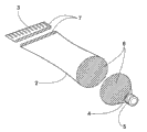
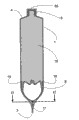
Fig. 1 illustrates the block diagram of deformable distribution pipe 1.
Fig. 2 illustrates the block diagram of deformable distribution pipe 1, and this deformable distribution pipe 1 is divided three parts to illustrate: shaping opening 4, sealed end 3 and deformable body 2.
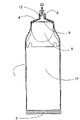
Fig. 3 illustrates the front elevation of deformable distribution pipe 1.
Fig. 4 illustrates the lateral plan of deformable distribution pipe 1.
Fig. 5 illustrates the section that passes through deformable distribution pipe 1 that obtains from the front elevation of deformable distribution pipe 1.
Fig. 6 illustrates the block diagram of device 8.
Fig. 7 illustrates the block diagram of device 8, and this device 8 is divided three parts to illustrate: device afterbody 10, device body 11 and device top 9.
Fig. 8 illustrates the lateral plan of device 8.
Fig. 9 illustrates the front elevation of device 8.
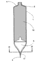
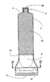
Figure 10 illustrates the section that passes through deformable distribution pipe 1 that obtains from the lateral plan of deformable distribution pipe 1, wherein installs 8 and is positioned at the appropriate location at sealed end 3 places, has internal capacity 25 in the deformable distribution pipe 1.
Figure 11 illustrates the section that passes through deformable distribution pipe 1 that obtains from the lateral plan of deformable distribution pipe 1, wherein installs 8 and is positioned at the appropriate location at sealed end 3 places, has content 16 in the deformable distribution pipe 1.
Figure 12 illustrates the section that passes through deformable distribution pipe 1 that obtains from the front elevation of deformable distribution pipe 1, wherein installs 8 and is positioned at the appropriate location at sealed end 3 places, has internal capacity 25 in the deformable distribution pipe 1.
Figure 13 illustrates the section that passes through deformable distribution pipe 1 that obtains from the front elevation of deformable distribution pipe 1, wherein installs 8 and is positioned at the appropriate location at sealed end 3 places, has content 16 in the deformable distribution pipe 1.
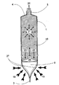
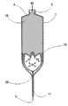
Figure 14 illustrates the section that passes through deformable distribution pipe 1 that obtains from the lateral plan of deformable distribution pipe 1, wherein installs 8 and is positioned at the appropriate location at sealed end 3 places and effect has external force 19.
Figure 15 illustrates the section that passes through deformable distribution pipe 1 that obtains from the lateral plan of deformable distribution pipe 1, installs wherein that 8 midway location places between sealed end 3 and shaping opening 4 are positioned at the appropriate location and effect has external force 19.
Figure 16 illustrates the section that passes through deformable distribution pipe 1 that obtains from the lateral plan of deformable distribution pipe 1, installs wherein that 8 midway location places between sealed end 3 and shaping opening 4 are positioned at the appropriate location and effect has external force 24.
Figure 17 illustrates the section that passes through deformable distribution pipe 1 that obtains from the front elevation of deformable distribution pipe 1, installs wherein that 8 midway location places between sealed end 3 and shaping opening 4 are positioned at the appropriate location and effect has external force 24.
Figure 18 illustrates the section that passes through deformable distribution pipe 1 that obtains from the lateral plan of deformable distribution pipe 1, wherein installs 8 and is positioned at the appropriate location at shaping opening 4 places.
Figure 19 illustrates the section that passes through deformable distribution pipe 1 that obtains from the front elevation of deformable distribution pipe 1, wherein installs 8 and is positioned at the appropriate location at shaping opening 4 places.
Figure 20 is illustrated in the block diagram of the device of seeing at 9 places, device top 8.
Figure 21 is illustrated in the block diagram of the device of seeing at device afterbody 10 places 8.
Figure 22 is illustrated in the block diagram of the device of seeing at device afterbody 10 places 8, wherein for the sake of clarity installs 8 and is divided two parts to illustrate: rigid frame 29 and deformable central portion 28.
Figure 23 illustrates from the block diagram of the deformable central portion 28 seen of direction of device afterbody 10, and wherein for the sake of clarity deformable body 16 is divided two parts to illustrate: device body 11 and device top 9.
Figure 24 illustrates the lateral plan of device 8.
Figure 25 illustrates the section that passes through device 8 that obtains from the side.
Figure 26 illustrates the front elevation of device 8.
Figure 27 illustrates the section that passes through deformable distribution pipe 1 that obtains from the lateral plan of deformable distribution pipe 1, wherein installs 8 and is positioned at the appropriate location at sealed end 3 places, has internal capacity 25 in the deformable distribution pipe 1.
Figure 28 illustrates the section that passes through deformable distribution pipe 1 that obtains from the lateral plan of deformable distribution pipe 1, wherein installs 8 and is positioned at the appropriate location at sealed end 3 places, has content 16 in the deformable distribution pipe 1.
Figure 29 illustrates the section that passes through deformable distribution pipe 1 that obtains from the front elevation of deformable distribution pipe 1, wherein installs 8 and is positioned at the appropriate location at sealed end 3 places, has internal capacity 25 in the deformable distribution pipe 1.
Figure 30 illustrates the section that passes through deformable distribution pipe 1 that obtains from front elevation, wherein installs 8 and is positioned at the appropriate location at sealed end 3 places, has content 16 in the deformable distribution pipe 1.
Figure 31 illustrates the section that passes through deformable distribution pipe 1 that obtains from the lateral plan of deformable distribution pipe 1, wherein installs 8 and is positioned at the appropriate location at sealed end 3 places, and the sealed and effect in aperture 5 has external force 19.
Figure 32 illustrates the section that passes through deformable distribution pipe 1 that obtains from the lateral plan of deformable distribution pipe 1, wherein installs 8 and is positioned at the appropriate location at sealed end 3 places, and the not sealed and effect in aperture 5 has external force 19.
Figure 33 illustrates the section that passes through deformable distribution pipe 1 that obtains from the lateral plan of deformable distribution pipe 1, wherein installs 8 roughly midway location places between sealed end 3 and shaping opening 4 and is positioned at the appropriate location, and the not sealed and effect in aperture 5 has external force 19.
Figure 34 illustrates the section that passes through deformable distribution pipe 1 that obtains from the lateral plan of deformable distribution pipe 1, wherein installs 8 roughly midway location places between sealed end 3 and shaping opening 4 and is positioned at the appropriate location, and the not sealed and effect in aperture 5 has pressure 24.
Figure 35 illustrates the section that passes through deformable distribution pipe 1 that obtains from the front elevation of deformable distribution pipe 1, wherein installs 8 roughly midway location places between sealed end 3 and shaping opening 4 and is positioned at the appropriate location, and the not sealed and effect in aperture 5 has pressure 24.
Figure 36 illustrates the section that passes through deformable distribution pipe 1 that obtains from the lateral plan of deformable distribution pipe 1, wherein installs 8 and is positioned at the appropriate location at shaping opening 4 places, and the not sealed and effect in aperture 5 has external force 19.
Figure 37 illustrates the section that passes through deformable distribution pipe 1 that obtains from the front elevation of deformable distribution pipe 1, wherein installs 8 and is positioned at the appropriate location at shaping opening 4 places, and aperture 5 is not sealed.
Figure 38 illustrates the section that passes through deformable distribution pipe 1 that obtains from the lateral plan of deformable distribution pipe 1, wherein install 8 roughly midway location places between sealed end 3 and shaping opening 4 and be positioned at the appropriate location, and content retraction 34 works.
Figure 39 is illustrated in the block diagram of the device of seeing at 9 places, device top 8.
Figure 40 is illustrated in the block diagram of the device of seeing at 9 places, device top 8, wherein for the sake of clarity installs 8 and is divided three parts to illustrate: device top 9, device afterbody 10 and device body 11.
Figure 41 illustrates device top 9, for the sake of clarity installs top 9 and separates with the remainder of device 8.
Figure 42 illustrates the lateral plan of device 8.
Figure 43 illustrates the section that passes through device 8 that obtains from lateral plan.
Figure 44 illustrates the front elevation of device 8.
Figure 45 illustrates the section that passes through deformable distribution pipe 1 that obtains from the lateral plan of deformable distribution pipe 1, wherein installs 8 (also being analysed and observe) and is positioned at the appropriate location at sealed end 3 places, and have internal capacity 25 in the deformable distribution pipe 1.
Figure 46 illustrates the section that passes through deformable distribution pipe 1 that obtains from the lateral plan of deformable distribution pipe 1, wherein installs 8 (also being analysed and observe) and is positioned at the appropriate location at sealed end 3 places, has content 16 in the sealed and deformable distribution pipe 1 in aperture 5.
Figure 47 illustrates the section that passes through deformable distribution pipe 1 that obtains from the front elevation of deformable distribution pipe 1, wherein installs 8 and is positioned at the appropriate location at sealed end 3 places, has internal capacity 25 in the deformable distribution pipe 1.
Figure 48 illustrates the section that passes through deformable distribution pipe 1 that obtains from the front elevation of deformable distribution pipe 1, wherein installs 8 and is positioned at the appropriate location at sealed end 3 places, has content 16 in the sealed and deformable distribution pipe 1 in aperture 5.
Figure 49 illustrates the section that passes through deformable distribution pipe 1 that obtains from the lateral plan of deformable distribution pipe 1, wherein installs 8 and is positioned at the appropriate location at sealed end 3 places, and effect has external force 19 and aperture 5 sealed.
Figure 50 illustrates the section that passes through deformable distribution pipe 1 that obtains from the lateral plan of deformable distribution pipe 1, wherein installs 8 and is positioned at the appropriate location at sealed end 3 places, and effect has external force 19 and aperture 5 not sealed.
Figure 51 illustrates the section that passes through deformable distribution pipe 1 that obtains from the lateral plan of deformable distribution pipe 1, wherein installs 8 roughly midway location places between sealed end 3 and shaping opening 4 and is positioned at the appropriate location, and effect has external force 19 and aperture 5 not sealed.
Figure 52 illustrates the section that passes through deformable distribution pipe 1 that obtains from the lateral plan of deformable distribution pipe 1, wherein installs 8 roughly midway location places between sealed end 3 and shaping opening 4 and is positioned at the appropriate location, and effect has pressure 24 and aperture 5 not sealed.
Figure 53 illustrates the section that passes through deformable distribution pipe 1 that obtains from the front elevation of deformable distribution pipe 1, wherein installs 8 roughly midway location places between sealed end 3 and shaping opening 4 and is positioned at the appropriate location, and effect has pressure 24 and aperture 5 not sealed.
Figure 54 illustrates the section that passes through deformable distribution pipe 1 that obtains from the lateral plan of deformable distribution pipe 1, wherein install 8 (also being analysed and observe) and be positioned at the appropriate location at shaping opening 4 places, and aperture 5 is not sealed.
Figure 55 illustrates the section that passes through deformable distribution pipe 1 that obtains from the front elevation of deformable distribution pipe 1, wherein install 8 and be positioned at the appropriate location at shaping opening 4 places, and aperture 5 is not sealed.
Figure 56 illustrates the section that passes through deformable distribution pipe 1 that obtains from the lateral plan of deformable distribution pipe 1, wherein install 8 roughly midway location places between sealed end 3 and shaping opening 4 and be positioned at the appropriate location, and content retraction 34 works.
The specific embodiment
(only referring to figs. 1 through Figure 19) only illustrates an optional embodiment of the present invention with by way of example hereinafter with reference to the accompanying drawings, is referred to as embodiment A.
Embodiments of the present invention A is a kind of device that provides as the separation insert of deformable distribution pipe, and this is called as device 8 below device.Hereinafter comprise member and mode of operation explanation representative type deformable distribution pipe with reference to device 8.Be called as deformable distribution pipe 1 below this deformable distribution pipe.
Shaping opening 4 at one end has shaping aperture 5, and this shaping aperture 5 is used to open and reseals shaping opening 4, thereby allows to distribute the content 16 of deformable distribution pipe 1.
5 beginnings become bigger shape engaging part with deformable body 2 to the shape and size of shaping opening 4 from the shaping aperture.Be called as cross-sectional plane 6 below the junction of shaping opening 4 and deformable body 2, and in Fig. 2, illustrate, in Fig. 3 and Fig. 4, indicate with line I-I with shade line.
The rigidity of shaping opening 4 changes, and its rigidity is obviously greater than deformable body 2, thereby forces deformable body 2 to take identical shape and size at cross-sectional plane 6 places.
Flattening then this material for good and all to be sealed or fuses together by the material that makes deformable distribution pipe 1 forms sealed end 3, thereby no longer includes internal capacity or space in this is in deformable distribution pipe 1.
By seal deformable distribution pipe 1 at sealed end 3 places, deformable body 2 is forced near sealed end 3 places and takes specific cross-sectional plane.Be called as cross-sectional plane 7 below the hollow cross-section that forms by deformable body 2 in the zone before being about to become the part of sealed end 3, and in Fig. 2, illustrate, and usefulness line II-II indicates in Fig. 3 and Fig. 4 with shade line.
Be called as space 17 below the volume between cross-sectional plane 7 and the sealed end 3.
Therefore, the shape of deformable body 2 changes to cross-sectional plane 7 along the length of deformable body 2 from cross-sectional plane 6, thereby makes deformable body 2 have internal capacity.
The shape of device body 11 is converted to cross-sectional plane 14 smoothly from cross-sectional plane 13.
Shown in Fig. 7,8 and 9, device afterbody 10 is formed along directly being tapered or becoming circle from cross-sectional plane 14 away from the direction of installing top 9 and is an end.The shape and size of device afterbody 10 form and make that this device afterbody 10 will be assemblied in the space 17 when device 8 is positioned at the appropriate location at sealed end 3 places in deformable distribution pipe 1.
Interior shape and internal dimensions at the cross-sectional plane 7 of the shape and size of the cross-sectional plane 14 at device afterbody 10 places and deformable distribution pipe 1 are complementary.
When device 8 is positioned at the appropriate location in deformable distribution pipe 1, cross-sectional plane 14 at device afterbody 10 places forces in the shape and size along the internal cross section of any position deformable body 2 of the length of deformable body 2 identical with cross-sectional plane 14, contacts with deformable body 2 at this location means afterbody 10.
Interior shape and internal dimensions at the cross-sectional plane 6 of the shape and size of cross-sectional plane 13 at device 9 places, top and deformable distribution pipe 1 are complementary.
When device 8 is positioned at the appropriate location in deformable distribution pipe 1, the cross-sectional plane 13 at device top 9 forces in the shape and size along the internal cross section of any position deformable body 2 of the length of deformable body 2 identical with cross-sectional plane 13, contacts with deformable body 2 at this location means top 9.
Figure 10 and 12 is illustrated in sealed end 3 places and is positioned at deformable distribution pipe 1 in-to-in device 8.In deformable distribution pipe 1, between device top 9 and shaping opening 4, form internal capacity 25.As Figure 11 and shown in Figure 13, content 16 is accommodated in the internal capacity 25, and part is positioned at shaping opening 4.Space 17 is taken part by device afterbody 10.
Applying between the cross-sectional plane 13 of the inside face of deformable body 2 and device 8 makes and forms sealing at the inside face of deformable body 2 with between installing 8, thereby even also can prevent content 16 under pressure any crossing the border taken place.
When as the part of the assembly that forms device 8 and be not in any pressure or power effect following time, the shape of flexible seals 15 is similar to cross-sectional plane 13, but its size is a bit larger tham cross-sectional plane 13.Thereby the cross-sectional plane of flexible seals 15 also is a bit larger tham the internal cross section owing to the deformable body 2 that exists device 8 to form in the deformable body 2.
When device 8 was positioned at the appropriate location in deformable distribution pipe 1, flexible seals 15 was compressed with in the internal cross section that is assemblied in deformable body 2.
Be compressed to be assemblied in flexible seals 15 in the deformable distribution pipe 1 under pressure against the inside face of deformable body 2, thereby any enhancing sealing of crossing the border or the further sealing of opposing content 16 are provided, have still allowed device 8 in distribution pipe 1, to move freely simultaneously.
When as the part of the assembly that forms device 8 and be not in any pressure or power effect following time, retaining element 26 is compliant members, and the outside dimension of these parts must be assemblied in the size of cross section taken in correspondence 7 wherein greater than cross-sectional plane 14 and this parts.
When device 8 is positioned at the appropriate location in deformable distribution pipe 1, retaining element 26 is compressed and is assemblied in by this way in the cross-sectional plane 7, if that is: installing 8 directions towards shaping opening 4 moves, then this retaining element further compresses, thereby allows device 8 to move freely in distribution pipe 1 towards the direction of shaping opening 4.But, when device 8 is positioned at the appropriate location in deformable distribution pipe 1, retaining element 26 is compressed and is assemblied in by this way in the cross-sectional plane 7, if that is: installing 8 directions towards sealed end 3 moves, then retaining element 26 is forced on the inside face of deformable distribution pipe 1 or enters in this inside face, is locked in this place and anti-locking apparatus 8 is moved further along sealed end 3 directions thereby will install 8.
Shown in Figure 18 and 19, the outer shape at device top 9 will be such shape and size, and promptly these shape and size make this device top to move in the shaping opening 4 of deformable distribution pipe 1, thereby discharge content 16 as much as possible.
Shown in Figure 18 and 19, the device stopper 12 at device top 9 will be such shape and size, and promptly these shape and size make this device stopper to move in shaping aperture 5, still allow to discharge content 16 simultaneously.
Shown in the arrow in Figure 14 and 15 19, the user directly or indirectly applies external pressure on the outside of deformable distribution pipe 1.The result of external pressure 19 produces directive effect towards shaping opening 4 to make a concerted effort 20 on device 8.20 act on the content 16 that holds in the deformable distribution pipe 1 by installing 8 then with joint efforts, thereby in content 16, produce internal pressure 21.
Internal pressure 21 will produce opposite force 23 on device 8.Opposite force 23 opposings make a concerted effort 20, and are used to make device 8 to move towards the direction of sealed end 3, but any this moving all stoped by retaining element 26.
The effect that sealing between the device 8 and the inside face of deformable body 2 combines with the additional seal that flexible seals 15 provides guarantees that content 16 stays the internal capacity 25 of shaping opening 4 sides that are positioned at device 8.
When shaping aperture 5 is not sealed, internal pressure 21 will force content 16 as shown in arrow 22 by 5 discharges of shaping aperture.
At first, when content 16 begins from 1 discharge of deformable distribution pipe, internal pressure 21 will reduce, and opposite force 23 also will correspondingly reduce.Thereby, 20 opposite forces 23 that will generate of making a concerted effort greater than internal pressure 21 by content 16.
Shown in Figure 14 and 15, make a concerted effort 20 with the difference of opposite force 23 by 18 solutions of the internal friction power between the inside face that is present in device 8 and deformable distribution pipe 1.
When content 16 continued to discharge from deformable distribution pipe 1, opposite force 23 correspondingly further reduced.Finally, making a concerted effort 20 will be greater than the combination of opposite force 23 and internal friction power 18, and device 8 beginnings this moment move forward along 20 the direction of making a concerted effort, and this direction is towards shaping opening 4.
When device 8 when shaping opening 4 moves, internal pressure 21 will maintain certain level, and promptly content 16 will continue to discharge by shaping aperture 5 under this level, and the size in space 17 will increase, make deformable body 2 become empty and be in flat or flat form almost, as shown in figure 15.
With reference to Figure 16 and 17, internal pressure 21 also can be by at shaping opening 4 with install the external force 24 that acts between 8 the position on the deformable body 2 and produce.
In above-mentioned example, opposite force 23 can be used for making device 8 to move towards sealed end 3 away from shaping opening 4.Retaining element 26 is designed to prevent that locking apparatus 8 moves towards the direction of sealed end 3, so the internal pressure 21 that external force 24 produces also will cause content 16 as shown in arrow 22 by 5 discharges of shaping aperture.
When device 8 during, make device top 9 mobile shaping opening 4 in the interior shape of shaping opening 4 and the shape and size at the corresponding device of internal dimensions top 9, so that discharge content 16 as much as possible near shaping opening 4.In the case, shown in Figure 18 and 19, even the shape and size of device stopper 12 form when making in device stopper 12 has moved into shaping aperture 5, content 16 still can flow through shaping aperture 5.
The user can change external pressure 19 or 24 so as can thereby the rate of discharge of control content thing 16.
When the user removed external pressure 19 or external pressure 24, the power as a result that produces in deformable distribution pipe 1 and device 8 was removed, so content 16 stops to flow.
Because retaining element 26 anti-locking apparatus 8 move towards sealed end 3 backward,, content 16 gets ready for further using so will being retained in the regional interior of shaping opening 4 always.
(only Fig. 1 to Fig. 5 and other Figure 20 to 38) only illustrates an optional embodiment of the present invention with by way of example hereinafter with reference to the accompanying drawings, is referred to as embodiment B.
Embodiments of the present invention B is a kind of device that provides as the independent insert of deformable distribution pipe, and this is called as device 8 below device.Hereinafter comprise member and mode of operation explanation representative type deformable distribution pipe with reference to device 8.Be called as deformable distribution pipe 1 below this deformable distribution pipe.
Shaping opening 4 at one end has shaping aperture 5, and this shaping aperture 5 is used to open and reseals shaping opening 4, thereby allows to distribute the content 16 of deformable distribution pipe 1.
5 beginnings become bigger shape engaging part with deformable body 2 to the shape and size of shaping opening 4 from the shaping aperture.Be called as cross-sectional plane 6 below the junction of shaping opening 4 and deformable body 2, and in Fig. 2, illustrate, in Fig. 3 and Fig. 4, indicate with line I-I with shade line.
The rigidity of shaping opening 4 changes, and its rigidity is obviously greater than deformable body 2, thereby forces deformable body 2 to take identical shape and size at cross-sectional plane 6 places.
Flattening then this material for good and all to be sealed or fuses together by the material that makes deformable distribution pipe 1 forms sealed end 3, thereby no longer includes internal capacity or space in this is in deformable distribution pipe 1.
By seal deformable distribution pipe 1 at sealed end 3 places, deformable body 2 is forced near sealed end 3 places and takes specific cross-sectional plane.Be called as cross-sectional plane 7 below the hollow cross-section that forms by deformable body 2 in the zone before being about to become the part of sealed end 3, and in Fig. 2, illustrate, and usefulness line II-II indicates in Fig. 3 and Fig. 4 with shade line.
Be called as space 17 below the volume between cross-sectional plane 7 and the sealed end 3.
Therefore, the shape of deformable body 2 changes to cross-sectional plane 7 along the length of deformable body 2 from cross-sectional plane 6, thereby makes deformable body 2 have internal capacity.
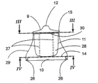
Deformable central portion 28 comprises device top 9 and device body 11, and for the sake of clarity this device top 9 and device body 11 illustrate in Figure 23 separatedly.One or more such materials of deformable central portion 28 usefulness are made, and promptly described material makes this deformable central portion to be compressed simultaneously correspondingly along another direction expansion or prolongation along a direction.
Suitable material can be the shaping crust that elastomeric material, foam rubber material, gel-type material, central authorities are filled with fluid or gel, and their any combination.
Retaining element 26 can be integrally molded on rigid frame 29, perhaps can form separating component by optional material.
For the sake of clarity, device top 9 and device body 11 are separated explanation, but they are single homogeneous parts.With reference to Figure 24,25 and 26, device top 9 comprises device stopper 12, this device stopper 12 is decreased to cross-sectional plane 13 after being transformed into bigger flexible seals 15 a little, molded or when fitting together when rigid frame 29 and deformable central portion 28, the periphery of the device collar 30 on the periphery of this cross-sectional plane 13 and the rigid frame 29 is consistent.Cross-sectional plane 13 illustrates with shade line on Figure 22 and 23, and uses line III-III indication at Figure 24, on Figure 25 and Figure 26.The shape of flexible seals 15 is similar to cross-sectional plane 13, but its size is slightly larger than cross-sectional plane 13.
Have a hole in the device collar 30, device body 11 will be placed by this hole.Shown in Figure 20 and 21, device body 11 is positioned within the size of cross-sectional plane 13, and is converted to smoothly and installs afterbody 10 and engage.Shown in Figure 21, the dotted line of tapered wall 27 in 24 and 25, when rigid frame 29 and deformable central portion 28 were molded together or fit together, tapered wall 27 was positioned at the volume or the profile of device body 11.
Shown in Figure 22 and 26, device afterbody 10 is formed along directly being tapered or becoming circle from cross-sectional plane 14 away from the direction of installing collar 30 and is the end.The shape and size of device afterbody 10 form and make that this device afterbody 10 will be assemblied in the space 17, as Figure 27 and shown in Figure 29 when device 8 is positioned at the appropriate location in sealed end 3 is in deformable distribution pipe 1.
Interior shape and internal dimensions at the cross-sectional plane 7 of the shape and size of the cross-sectional plane 14 at device afterbody 10 places and deformable distribution pipe 1 are complementary.
When device 8 is positioned at the appropriate location in deformable distribution pipe 1, cross-sectional plane 14 at device afterbody 10 places forces in the shape and size along the internal cross section of any position deformable body 2 of the length of deformable body 2 identical with cross-sectional plane 14, contacts or overlaps with deformable body 2 at this location means afterbody 10.
The interior shape and the internal dimensions of the shape and size of device collar 30 and cooresponding cross-sectional plane 13 and the cross-sectional plane 6 of deformable distribution pipe 1 are complementary.
When device 8 is positioned at the appropriate location in deformable distribution pipe 1, device collar 30 and cooresponding cross-sectional plane 13 force along the shape and size of the internal cross section of any position deformable body 2 of the length of deformable body 2 with to install collar 30 identical, contact or overlap with deformable body 2 at this location means collar 30.
Figure 27 and Figure 29 are illustrated in sealed end 3 places and are positioned at deformable distribution pipe 1 in-to-in device 8.In deformable distribution pipe 1, between device top 9 and shaping opening 4, generate internal capacity 25.As Figure 28 and shown in Figure 30, content 16 is accommodated in the internal capacity 25, and partly is contained in the shaping opening 4.Space 17 is taken part by device afterbody 10.
Applying between the collar 30 of the inside face of deformable body 2 and device 8 makes and forms sealing at the inside face of deformable body 2 with between installing 8, thereby even also can prevent content 16 under pressure any crossing the border taken place.
When as the part of the assembly that forms device 8 and be not in any pressure or power effect following time, the shape of flexible seals 15 is similar to cross-sectional plane 13, but its size is a bit larger tham cross-sectional plane 13.Thereby the cross-sectional plane of flexible seals 15 also is a bit larger tham the internal cross section owing to the deformable body 2 that exists device 8 to form in the deformable body 2.
When device 8 was positioned at the appropriate location in deformable distribution pipe 1, flexible seals 15 was compressed with in the internal cross section that is assemblied in deformable body 2.
Be compressed to be assemblied in flexible seals 15 in the deformable distribution pipe 1 under pressure against the inside face of deformable body 2, thereby any enhancing sealing of crossing the border or the further sealing of opposing content 16 are provided, have still allowed device 8 in distribution pipe 1, to move freely simultaneously.
When as the part of the assembly that forms device 8 and be not in any pressure or power effect following time, retaining element 26 is compliant members, and the outside dimension of these parts must be assemblied in the size of cross section taken in correspondence 7 wherein greater than cross-sectional plane 14 and this parts.
When device 8 is positioned at the appropriate location in deformable distribution pipe 1, retaining element 26 is compressed and is assemblied in by this way in the cross-sectional plane 7, move if that is: install 8 directions towards shaping opening 4, then this retaining element further compresses, thereby allows device 8 to move freely in distribution pipe 1.But, if install 8 beginnings along moving away from the direction of shaping opening 4 direction towards sealed end 3, then retaining element 26 is forced on the inside face of deformable distribution pipe 1 or enters in this inside face, is locked in this place and anti-locking apparatus 8 and is moved further along the direction of sealed end 3 thereby will install 8.
Shown in Figure 36 and 37, the outer shape at device top 9 will be that such shape and size or deformable is such shape and size, promptly these shape and size make this device top to move in the shaping opening 4 of deformable distribution pipe 1, thereby discharge content 16 as much as possible.
Shown in Figure 36 and 37, the device stopper 12 at device top 9 will be that such shape and size or deformable is such shape and size, and promptly these shape and size make this device stopper to move in shaping aperture 5, still can discharge content 16 simultaneously.
With reference to Figure 31, it is as shown in arrow 19 that the user directly or indirectly applies external pressure in the outside of deformable distribution pipe 1.The result who acts on the external pressure 19 on the device 8 by deformable distribution pipe 1 produces directive effect towards shaping opening 4 to make a concerted effort 20 on device 8.20 act on the content 16 that holds in the deformable distribution pipe 1 by installing 8 then with joint efforts, thereby in content 16, produce internal pressure 21.Lid 35 is shown as the method for seal orifice 5.
Make a concerted effort 20 for external pressure 19 being converted to act on the content 16, deformable central portion 28 will bear following being called as the internal forces or the internal pressure 31 of " device pressure 31 ".
In addition, depend on the material behavior of deformable central portion 28, another result of external pressure 19 compresses as shown in figure 31 or twists deformable central portion 28.This compression or distortion are illustrated by the differently contoured of deformable distribution pipe 1 that be compressed in the not compressed deformable distribution pipe in Figure 28 1 and Figure 31.This compression or distortion are also by differently contoured the illustrating between the new profile of the dotted line of the not compressed deformable distribution pipe 1 shown in Reference numeral 19 places and deformable distribution pipe 1 also shown in Figure 31 and deformable central portion 28 among Figure 31.Device 8 also is designed to be in above-mentioned be compressed or during twisted state when device 8, and device 8 forms of taking of exterior three dimensional as a result make external pressure 19 continue to produce with joint efforts 20.
Internal pressure 21 will produce opposite force 23 on device 8.Produce internal friction power 18 between the inside face of device 8 and deformable distribution pipe 1.Opposite force 23 combines with internal friction power 18 to resist makes a concerted effort 20.
Sealing effectiveness between the device 8 and the inside face of deformable body 2 guarantees that content 16 stays the internal capacity 25 of shaping opening 4 sides that are positioned at device 8.When internal pressure 21 increased, device pressure 31 correspondingly increased, and will further improve the effectiveness of flexible seals 15 like this.
With reference to Figure 32, when shaping aperture 5 is not sealed, internal pressure 21 will make that content 16 beginning is as shown in arrow 22 and be discharged from by shaping aperture 5.
At first, when content 16 when deformable distribution pipe 1 is discharged, holding residue content 16 required volumes will reduce, this causes internal pressure 21 correspondingly to reduce then.In the case, 21 can not be reversed power 23 counteractings with joint efforts, thereby make deformable central portion 28 in internal capacity 25, twist.Deformable central portion 28 is along making a concerted effort 20 direction and towards will being called as " distortion volume 33 " below the distortion of shaping opening 4, and in Figure 32 with Reference numeral 33 indications.
The distortion of deformable central portion 28 will cause producing in the material of deformable central portion 28 or the storage subsidiary load, and these will be called as " storage power 32 " and indicate with arrow 32 in Figure 31 and 32 below subsidiary load.
Optionally, distortion volume 33 can reach its design maximum twisted state, 20 is enough big if make a concerted effort this moment, then also can begin to overcome internal friction power 18, and install 8 as an integral unit begin deformable distribution pipe 1 in edge with joint efforts 20 direction, promptly move forward towards shaping opening 4.
By moving forward like this, device 8 will as one man reduce the size of internal capacity 25 with the minimizing of the volume of the remainder of content 16, thereby internal pressure 21 is remained on certain level, and content 16 will continue by 5 discharges of shaping aperture under this level.When device 8 when shaping opening 4 moves, the length in space 17 will increase, make deformable body 2 become empty and as shown in figure 33 space 17 be in flat on every side or flat form almost.
With reference to Figure 36 and 37, when device 8 during near shaping opening 4, the shape and size at device top 9 will be twisted into interior shape and the internal dimensions corresponding to shaping opening 4, so that discharge content 16 as much as possible.In the case, also shown in Figure 36 and 37, device stopper 12 has such shape and size and maybe can twist and be such shape and size, even when making in device stopper 12 has moved into shaping aperture 5, content 16 still can flow through shaping aperture 5.
The user can change external pressure 19 in case can thus the rate of discharge of control content thing 16.
When the user removed external pressure 19, the power of setting up in deformable distribution pipe 1 and device 8 as a result will remove with the order opposite with setting up of these power.
Therefore, at first, device 8 will stop to move as an integral unit, thereby content 16 will stop to flow.Secondly, storage power 32 will make distortion volume 33 its virgin states of withdrawal.At this moment, but the combination of two kinds of selection operations one or both of can take place by design.
With reference to Figure 34 and 35, internal pressure 21 also can be by at shaping opening 4 with install the external force 24 that acts between 8 the position on the deformable body 2 and generate.
When external force 24 produced internal pressure 21, the opposite force 23 that causes can be used for making device 8 to move along the direction of opposite force 23 and towards sealed end 3 as an integral unit.Retaining element 26 anti-locking apparatus 8 move towards the direction of sealed end 3.Therefore, opposite force 23 will act on the deformable central portion 28 so that its direction distortion along opposite force 23.But deformable central portion 28 can prevent from along the direction of opposite force 23 any distortion or compression to take place with respect to the location of rigid frame 29 and the constraint of deformable body 2.Therefore, if shaping aperture 5 is not sealed, it is as shown in arrow 22 by 5 discharges of shaping aperture that then the internal pressure 21 that generates in external force 24 will cause content 16.
Because retaining element 26 anti-locking apparatus 8 move towards sealed end 3 backward, so content 16 always is present in shaping opening 4 places rightly for further use is ready.
(only Fig. 1 to Fig. 5 and other Figure 39 to 56) only illustrates an optional embodiment of the present invention with by way of example hereinafter with reference to the accompanying drawings, is referred to as embodiment C.
Embodiments of the present invention C is a kind of device that provides as the independent insert of deformable distribution pipe, and this is called as device 8 below device.Hereinafter comprise member and mode of operation explanation representative type deformable distribution pipe with reference to device 8.Be called as deformable distribution pipe 1 below this deformable distribution pipe.
Shaping opening 4 at one end has shaping aperture 5, and this shaping aperture 5 is used to open and reseals shaping opening 4, thereby allows to distribute the content 16 of deformable distribution pipe 1.
5 beginnings become bigger shape engaging part with deformable body 2 to the shape and size of shaping opening 4 from the shaping aperture.Be called as cross-sectional plane 6 below the junction of shaping opening 4 and deformable body 2, and in Fig. 2, illustrate, in Fig. 3 and Fig. 4, indicate with line I-I with shade line.
Shaping opening 4 is stiffness change, and its rigidity is obviously greater than deformable body 2, thereby forces deformable body 2 to take identical shape and size at cross-sectional plane 6 places.
Flattening then this material for good and all to be sealed or fuses together by the material that makes deformable distribution pipe 1 forms sealed end 3, thereby no longer includes internal capacity or space in this is in deformable distribution pipe 1.
By seal deformable distribution pipe 1 at sealed end 3 places, deformable body 2 is forced near sealed end 3 places and takes specific cross-sectional plane.Be called as cross-sectional plane 7 below the hollow cross-section that forms by deformable body 2 in the zone before being about to become the part of sealed end 3, and in Fig. 2, illustrate, and usefulness line II-II indicates in Fig. 3 and Fig. 4 with shade line.
Be called as space 17 below the volume between cross-sectional plane 7 and the sealed end 3.
Therefore, the shape of deformable body 2 changes to cross-sectional plane 7 along the length of deformable body 2 from cross-sectional plane 6, thereby makes deformable body 2 have internal capacity.
As being clearly shown that in Figure 41 and 43, deformable central portion 27 is between device stopper 12 and flexible seals 15.
The shape of device body 11 changes to cross-sectional plane 14 smoothly from cross-sectional plane 13.
Shown in Figure 39,40 and 44, device afterbody 10 is formed along directly being tapered or becoming circle from cross-sectional plane 14 away from the direction of installing top 9 and is an end.The shape and size of device afterbody 10 form and make that this device afterbody 10 will be assemblied in the space 17, see Figure 45 and Figure 47 when device 8 is positioned at the appropriate location in sealed end 3 is in deformable distribution pipe 1.
Interior shape and internal dimensions at the cross-sectional plane 7 of the shape and size of the cross-sectional plane 14 at device afterbody 10 places and deformable distribution pipe 1 are complementary.
When device 8 is positioned at the appropriate location in deformable distribution pipe 1, cross-sectional plane 14 at device afterbody 10 places forces take the shape and size identical with cross-sectional plane 14 along the internal cross section of any position deformable body 2 of the length of deformable body 2, contacts with deformable body 2 at this position device afterbody 10.
The interior shape and the internal dimensions of the shape and size of the cross-sectional plane 13 at device 9 places, top and the cross-sectional plane 6 of deformable distribution pipe 1 are complementary.
When device 8 is positioned at the appropriate location in deformable distribution pipe 1, the cross-sectional plane 13 at device 9 places, top forces take the shape and size identical with cross-sectional plane 13 along the internal cross section of any position deformable body 2 of the length of deformable body 2, contacts with deformable body 2 at this device top, position 9.
Figure 45 and Figure 47 are illustrated in sealed end 3 places and are placed in deformable distribution pipe 1 in-to-in device 8.Can find out that the shape of deformable distribution pipe 1 is suitable for the cross-sectional plane 13 and the cross-sectional plane 14 of device 8.In deformable distribution pipe 1, between device top 9 and shaping opening 4, form internal capacity 25.Space 17 is taken part by device afterbody 10.
As Figure 46 and shown in Figure 48, content 16 is accommodated in the internal capacity 25 and part is contained in the shaping opening 4.Lid 35 is depicted as a kind of method of seal orifice 5.
Assembling between the inside face of deformable body 2 and device 8 the cross-sectional plane 13 makes and forms sealing at the inside face of deformable body 2 with between installing 8, thereby even still can prevent any the crossing the border of content 16 generations when content 16 is in pressure effect following time.
When not being in any pressure or power effect following time, the shape of flexible seals 15 will be similar to cross-sectional plane 13, but its size is a bit larger tham cross-sectional plane 13.Thereby the cross-sectional plane of flexible seals 15 also is a bit larger tham the internal cross section owing to the deformable body 2 that exists device 8 to form in the deformable body 2.
When device 8 was positioned at the appropriate location in deformable distribution pipe 1, flexible seals 15 was compressed with in the internal cross section that is assemblied in deformable body 2.
Be compressed to be assemblied in flexible seals 15 in the deformable distribution pipe 1 under pressure against the inside face of deformable body 2, thereby any improvement of crossing the border that opposing content 16 is provided strengthens sealing or further sealing, still allows device 8 to move freely in distribution pipe 1 simultaneously.
When not being in any pressure or power effect following time, retaining element 26 is compliant members, and the outside dimension of these parts must be assemblied in the size of cross section taken in correspondence 7 wherein greater than cross-sectional plane 14 and this parts.
When device 8 is positioned at the appropriate location in deformable distribution pipe 1, retaining element 26 deflections or be compressed and be assemblied in by this way in the cross-sectional plane 7, if that is: installing 8 directions towards shaping opening 4 moves, then further deflection of retaining element or compression, thus still allow device 8 in deformable distribution pipe 1, to move freely.But, when device 8 is positioned at the appropriate location in deformable distribution pipe 1, retaining element 26 deflections or be compressed and be assemblied in by this way in the cross-sectional plane 7, if that is: installing 8 begins to move towards the direction of sealed end 3, then retaining element 26 is forced to enter in this inside face against the inside face or the expansion of deformable distribution pipe 1, is locked in this place and anti-locking apparatus 8 and is moved further towards the direction of sealed end 3 thereby will install 8.
With reference to Figure 54 and 55, the outer shape at device top 9 will be such shape and size or may be deformed to such shape and size, promptly these shape and size make this device top to move in the shaping opening 4 of deformable distribution pipe 1, thereby discharge content 16 as much as possible.
Shown in Figure 54 and 55, the device stopper 12 at device top 9 will be that such shape and size or deformable is such shape and size, and promptly these shape and size make this device stopper to move in shaping aperture 5, still can discharge content 16 simultaneously.
With reference to Figure 49, the user is as shown in arrow 19 directly or indirectly to apply external pressure to the outside of deformable distribution pipe 1.External pressure 19 acts on result on the device 8 by deformable distribution pipe 1 and produces in device 8 towards with joint efforts 20 of the direction of shape opening 4.20 act on the content 16 that holds in the deformable distribution pipe 1 by installing 8 then with joint efforts, thereby in content 16, produce internal pressure 21.
Internal pressure 21 will produce opposite force 23 on device 8.Produce internal friction power 18 between the inside face of device 8 and deformable distribution pipe 1.Opposite force 23 combines with internal friction power 18 and resists and make a concerted effort 20.
Make a concerted effort 20 for external pressure 19 being converted to act on the content 16, gas in device 8 and the central portion thereof or material will bear internal force or the internal pressure with arrow 28 expressions, this internal force or be called as " device pressure 28 " below the internal pressure.
In addition, depend on that another result that external pressure 19 combines with opposite force 23 compresses or recking means for cargo 8 as shown in figure 49 in material behavior and the gas in the central portion or the material of device 8.This compression or distortion are illustrated by the differently contoured of device 8 that be compressed among the not compressed device among Figure 46 8 and Figure 49.The dotted outline of the not compressed deformable distribution pipe 1 that this compression or distortion are also indicated with arrow 19 in Figure 49 and deformable distribution pipe 1 also shown in Figure 49 and install differently contoured illustrating between 8 the profile that is compressed now or twists.Device 8 also is designed to be in above-mentioned be compressed or during twisted state when device 8, and the form of exterior three dimensional as a result of the device of taking 8 makes external pressure 19 continue to produce with joint efforts 20.
Sealing effectiveness between the inside face of device 8 and deformable body 2 can guarantee that content 16 is retained in the internal capacity 25 of shaping opening 4 sides that are positioned at device top 9.Device pressure 28 will further improve or the inside face of intensifier 8 and deformable body 2 between sealing.
Internal pressure 21 also will be applied on the inner sealing surface 31, thereby any increase of the internal pressure 21 of the content 16 that is overcome with flexible seals 15 improves the effectiveness of flexible seals 15 pro rata.
With reference to Figure 50, when shaping aperture 5 is not sealed, internal pressure 21 will make content 16 beginnings as shown in arrow 22 by 5 discharges of shaping aperture.
At first, when content 16 by when deformable distribution pipe 1 is discharged, holding residue content 16 required volumes will reduce, this causes internal pressure 21 correspondingly to reduce then.In the case, make a concerted effort 20 can not to be reversed power 23 and to offset, thereby make a concerted effort 20 will make deformable central portion 27 along making a concerted effort 20 direction distortion.Deformable central portion 27 is along making a concerted effort 20 direction and towards being called as " distortion central portion 30 " below the distortion of shaping opening 4, as shown in Figure 50.
Deformable central portion 27 will cause producing in the material of device 8 or the storage subsidiary load to the distortion of distortion central portion 30, and these will be called as " storage power 29 " and use arrow 29 indications in Figure 50 below subsidiary load.
Distortion central portion 30 will continue distortion, and up to the combination and make a concerted effort 20 balances of storage power 29 with opposite force 23, and these internal force are at equilibrium.By such distortion, distortion central portion 30 will be offset the reducing of volume of the remainder of the content 16 that holds in the internal capacity 25, thereby internal pressure 21 is remained on certain level, and content 16 will continue mobile under this level.
When distortion central portion 30 reaches its design maximum twisted state, and make a concerted effort 20 this moment when overcoming internal friction power 18, device 8 do as a whole will begin deformable distribution pipe 1 in edge with joint efforts 20 direction, promptly move forward towards shaping opening 4.
By moving towards shaping opening 4 like this, device 8 will as one man reduce the size of internal capacity 25 with the minimizing of the residual volume of content 16, thereby internal pressure 21 is remained certain level, and content 16 will continue to discharge by shaping aperture 5 under this level.When device 8 when shaping opening 4 moves, the length in space 17 will increase, make deformable body 2 become empty and 17 be in flat on every side or flat form almost in the space as shown in figure 33.
With reference to Figure 54 and 55, when device 8 during near shaping opening 4, corresponding to or distortion make device top 9 in shaping opening 4, to move for the shape and size at the device top 9 of the interior shape of shaping opening 4 and internal dimensions so that discharge content 16 as much as possible.In the case, device stopper 12 has such shape and size, even when making in device stopper 12 has moved into shaping aperture 5, content 16 still can flow through shaping aperture 5.
The user can change external pressure 19 in case can thus the rate of discharge of control content thing 16.
When the user removed external pressure 19, the power of setting up in deformable distribution pipe 1 and device 8 as a result will remove with the order opposite with setting up these power.
Therefore, at first, device 8 will stop to move as an integral unit, thereby content 16 will stop to flow.Secondly, storage power 29 will make distortion central portion 30 its virgin states of withdrawal.At this moment, but one of two kinds of selection operations (or ideally, the combination of two kinds of operations) can take place by design.
With reference to Figure 52 and 53, internal pressure 21 also can be by at shaping opening 4 with install the external force 24 that acts between 8 the position on the deformable body 2 and generate.
When external force 24 produced internal pressure 21, the opposite force 23 that causes can be used for making device 8 to move towards sealed end 3 as the direction of an integral unit along opposite force 23.Retaining element 26 anti-locking apparatus 8 move towards the direction of sealed end 3.Therefore, opposite force 23 will act on the deformable central portion 27 so that its direction distortion along opposite force 23.But the constraint of 1 pair of device 8 of the design of deformable central portion 27 and deformable distribution pipe combines and can make deformable central portion 27 move required power greater than by the required power of aperture 5 discharge contents 16 along the direction of opposite force 23.Therefore, if shaping aperture 5 is not sealed, it is as shown in arrow 22 by 5 discharges of shaping aperture that then the internal pressure 21 that is generated by external force 24 will cause content 16.
Because the anti-locking apparatus 8 of retaining element 26 move towards sealed end 3 backward, so that content 16 will always be present in the zone of shaping opening 4 will be ready for further using.
Claims (19)
1. deformable distribution pipe, the second end that this deformable distribution pipe has the osed top first end and has pass through openings, when this pipe has been filled, can be by the distortion dispense contents of this pipe, this pipe comprises distribution device, content was arranged between this distribution device and the described opening usually when this distribution device can move and be positioned at filling in this pipe, thereby when the user applies external pressure on this pipe, can pass through this opening dispense contents; Wherein this distribution device be hollow and be filled with fluid, this distribution device comprises the device top, this device top contacts with content in this pipe and is arranged to and transmit pressure between the content of this pipe and the fluid in the described device, this distribution device also comprises sealing, sealing portion is used for sealing between this device and this pipe, wherein the thickness of this device top and sealing portion and material have abundant flexibility, make when described pipe applies external pressure, pressure on the fluid in the content of this pipe and this device increases, thereby this content can be assigned with, and when described device between used life moves in this pipe and described pipe when being out of shape, sealing portion applies increased pressure on the inside face of this pipe, produce whereby and keep from being in harmony sealing.
2. pipe according to claim 1, wherein said device top can be towards described opening direction distortion, thereby when at described device place when this pipe applies described external pressure, cause described fluid that described device top is out of shape towards described opening direction, on described content, apply increased pressure whereby, to pass through this opening dispense contents.
3. pipe according to claim 2, wherein the external pressure that applies to the content of this pipe by described device top towards the described closed end distortion of described pipe and transmitted, thereby the fluid in this device makes described sealing apply increased pressure on the inside face of this distribution pipe, stops the excessively boundary of content between described distribution device and described inside face between allotment period at content whereby.
4. according to the described pipe of aforementioned arbitrary claim, wherein when the user near described device place or the described device when described pipe applies external pressure and increases the pressure of the fluid in the described device whereby, and when the user away from the part place of described device when this pipe applies pressure on the fluid that is passed to this device on the content that external pressure increases this pipe whereby, the pressure that is applied to by described sealing on the inside face of this pipe increases.
5. pipe according to claim 1, wherein said device have rebound resilience and when discharging described external pressure, this device is back to not deformation state.
6. pipe according to claim 5, wherein when the top resilience of described device was back to not deformation state, the internal pressure of the content in this pipe reduced, and makes all the elements thing that is arranged in described opening part bounce back to this pipe.
7. pipe according to claim 1, wherein said device is slidably received in this pipe, thereby when described opening had produced distortion, the described external pressure that applies at this device place made this device towards described opening sliding motion, with dispense contents at described device top.
8. pipe according to claim 7, wherein said distribution device comprises retaining element, this retaining element is used to make described device towards described harness motion and stop the described closed end motion of described device towards described pipe.
9. described according to Claim 8 pipe, wherein said retaining element is suitable for pressing the inside face of this pipe, stops the described closed end motion of described device towards this pipe whereby.
10. pipe according to claim 1, wherein when described device in use moved to described the second end and described device top towards described shedding deformation, described device top forms catered to the interior shape of this pipe at this second end place.
11. pipe according to claim 10, wherein said device top is deformable in the described opening, thereby can distribute the content of this opening part.
12. pipe according to claim 1, wherein said distribution device form at its end place towards described first end and the internal cross section coupling of this pipe at this first end place.
13. pipe according to claim 1, wherein said device top is connected to the device afterbody, this device afterbody extends from described device top towards the first end of this pipe, and the cross-sectional area of this device afterbody begins from this device top to reduce to its end towards the first end of this pipe.
14. pipe according to claim 1, wherein said device comprises the crust that accommodates fluid.
15. pipe according to claim 1, wherein said fluid are gas.
16. pipe according to claim 1, wherein said fluid are liquid.
17. pipe according to claim 1, wherein said fluid are gel.
18. according to claim 15,16 or 17 described pipes, wherein said fluid is contained in the described device under internal pressure.
19. distribution device that is used for the described distribution pipe of aforementioned arbitrary claim.
Applications Claiming Priority (3)
| Application Number | Priority Date | Filing Date | Title |
|---|---|---|---|
| GB0525219.2 | 2005-12-10 | ||
| GB0525219A GB2433486B (en) | 2005-12-10 | 2005-12-10 | Deformable dispensing tube |
| PCT/GB2006/004589 WO2007066123A1 (en) | 2005-12-10 | 2006-12-08 | Tube dispensing device |
Publications (2)
| Publication Number | Publication Date |
|---|---|
| CN101336198A CN101336198A (en) | 2008-12-31 |
| CN101336198B true CN101336198B (en) | 2011-12-28 |
Family
ID=35735921
Family Applications (1)
| Application Number | Title | Priority Date | Filing Date |
|---|---|---|---|
| CN2006800524176A Expired - Fee Related CN101336198B (en) | 2005-12-10 | 2006-12-08 | Tube dispensing device |
Country Status (10)
| Country | Link |
|---|---|
| US (2) | US8499973B2 (en) |
| EP (1) | EP1976765B1 (en) |
| JP (1) | JP2009518246A (en) |
| CN (1) | CN101336198B (en) |
| AT (1) | ATE508963T1 (en) |
| DK (1) | DK1976765T3 (en) |
| ES (1) | ES2366578T3 (en) |
| GB (1) | GB2433486B (en) |
| PL (1) | PL1976765T3 (en) |
| WO (1) | WO2007066123A1 (en) |
Families Citing this family (10)
| Publication number | Priority date | Publication date | Assignee | Title |
|---|---|---|---|---|
| US20080302826A1 (en) * | 2007-06-09 | 2008-12-11 | Rich Jr Joseph | Plunger tube |
| KR101055936B1 (en) | 2009-02-14 | 2011-08-09 | 김성기 | Packaging tube with built-in drain |
| KR101022595B1 (en) * | 2010-01-27 | 2011-03-16 | 우종원 | A tube having extrude piston for viscosity substance |
| WO2011087335A2 (en) * | 2010-02-23 | 2011-07-21 | Woo Jong Won | Tube container having piston for dispensing viscous substances |
| EP2647583A1 (en) * | 2012-04-03 | 2013-10-09 | Marc Mamiye | Pinch tube with internal piston dispensing extractor |
| TW201502018A (en) * | 2013-04-09 | 2015-01-16 | Veycle Design Co Ltd | The method of squeezed body for gel container |
| WO2015160371A1 (en) * | 2014-04-15 | 2015-10-22 | Aa R&D Llc | Press-type dispensing container |
| WO2016113186A1 (en) * | 2015-01-15 | 2016-07-21 | Enzo Ferrarin | Container for flowing substances |
| KR20210015803A (en) * | 2018-04-27 | 2021-02-10 | 조엘 샬로위츠 | Food container and dispenser |
| KR102057825B1 (en) * | 2018-08-23 | 2019-12-20 | 모리스앤코 주식회사 | the tube wringer |
Citations (7)
| Publication number | Priority date | Publication date | Assignee | Title |
|---|---|---|---|---|
| US2777612A (en) * | 1951-05-15 | 1957-01-15 | Richard E Bensen | Compression type dispensing device |
| USRE27057E (en) * | 1968-12-23 | 1971-02-09 | Collapsible tubes with follower and tur method of filling thereof | |
| DE1959349A1 (en) * | 1969-11-26 | 1971-06-03 | Marek Josef Dipl Ing | Tube-like packaging for substances with a pulpy to liquid consistency |
| US4039103A (en) * | 1974-12-18 | 1977-08-02 | Hubert Juillet | Pressurized dispensing containers |
| US4102476A (en) * | 1977-02-22 | 1978-07-25 | Ciba-Geigy Corporation | Squeeze bottle dispenser with air check valve on cover |
| GB2257108A (en) * | 1991-06-25 | 1993-01-06 | John David Sheppard | Dispensing contents of sqeezable containers |
| CN1576177A (en) * | 2003-07-03 | 2005-02-09 | 增田胜利 | Fluid discharge pump and fluid container |
Family Cites Families (14)
| Publication number | Priority date | Publication date | Assignee | Title |
|---|---|---|---|---|
| US2361647A (en) * | 1942-05-20 | 1944-10-31 | Nyden Robert | Collapsible dispensing tube |
| US3184120A (en) * | 1963-08-16 | 1965-05-18 | Katherine Undi | Dispensing device for fluids |
| US3201003A (en) * | 1964-01-27 | 1965-08-17 | John D Wark | Dispensing container |
| US3493147A (en) * | 1968-02-05 | 1970-02-03 | Gene Ballin | Collapsible tube and follower |
| US3521795A (en) * | 1968-03-04 | 1970-07-28 | Bahl Associates | Full discharge dispensing container |
| JPS4812237U (en) * | 1971-06-21 | 1973-02-10 | ||
| FR2244678A1 (en) * | 1973-09-20 | 1975-04-18 | Raksanyi Arpad | Emptying system for squeeze tubes - uses deformable plug in tube end forcing tube contents out |
| DE3405547A1 (en) * | 1984-02-16 | 1985-08-14 | Hilti Ag, Schaan | PRESSING PISTON FOR CONTAINERS |
| JPH0615885Y2 (en) * | 1988-10-14 | 1994-04-27 | ポーラ化成工業株式会社 | Squeeze container |
| US5137177A (en) * | 1991-03-11 | 1992-08-11 | Willis Dale R | Dispensing tube with tubewall ribs and rear spherical plunger ball |
| US20020148854A1 (en) * | 2001-04-16 | 2002-10-17 | Egerhazy Joseph Bela | Flexible tube dispenser for viscous materials with movable insert and method of assembly |
| WO2004039685A1 (en) * | 2002-10-29 | 2004-05-13 | Enzo Ferrarin | Container for fluid substances like pastes or creams |
| JP4287304B2 (en) * | 2004-02-23 | 2009-07-01 | アース製薬株式会社 | Flexible paste tube with built-in extrusion promoter |
| AR050595A1 (en) * | 2005-06-22 | 2006-11-08 | Gaston Schang | PORTABLE CONTAINER FOR CONTAINING AND DISPENSING VISCOSE OR PASTRY SUBSTANCES |
-
2005
- 2005-12-10 GB GB0525219A patent/GB2433486B/en not_active Expired - Fee Related
-
2006
- 2006-12-08 DK DK06820458.5T patent/DK1976765T3/en active
- 2006-12-08 AT AT06820458T patent/ATE508963T1/en not_active IP Right Cessation
- 2006-12-08 JP JP2008543903A patent/JP2009518246A/en active Pending
- 2006-12-08 US US12/096,214 patent/US8499973B2/en not_active Expired - Fee Related
- 2006-12-08 CN CN2006800524176A patent/CN101336198B/en not_active Expired - Fee Related
- 2006-12-08 ES ES06820458T patent/ES2366578T3/en active Active
- 2006-12-08 PL PL06820458T patent/PL1976765T3/en unknown
- 2006-12-08 EP EP06820458A patent/EP1976765B1/en not_active Not-in-force
- 2006-12-08 WO PCT/GB2006/004589 patent/WO2007066123A1/en active Application Filing
-
2013
- 2013-07-01 US US13/932,458 patent/US20130299513A1/en not_active Abandoned
Patent Citations (7)
| Publication number | Priority date | Publication date | Assignee | Title |
|---|---|---|---|---|
| US2777612A (en) * | 1951-05-15 | 1957-01-15 | Richard E Bensen | Compression type dispensing device |
| USRE27057E (en) * | 1968-12-23 | 1971-02-09 | Collapsible tubes with follower and tur method of filling thereof | |
| DE1959349A1 (en) * | 1969-11-26 | 1971-06-03 | Marek Josef Dipl Ing | Tube-like packaging for substances with a pulpy to liquid consistency |
| US4039103A (en) * | 1974-12-18 | 1977-08-02 | Hubert Juillet | Pressurized dispensing containers |
| US4102476A (en) * | 1977-02-22 | 1978-07-25 | Ciba-Geigy Corporation | Squeeze bottle dispenser with air check valve on cover |
| GB2257108A (en) * | 1991-06-25 | 1993-01-06 | John David Sheppard | Dispensing contents of sqeezable containers |
| CN1576177A (en) * | 2003-07-03 | 2005-02-09 | 增田胜利 | Fluid discharge pump and fluid container |
Also Published As
| Publication number | Publication date |
|---|---|
| ATE508963T1 (en) | 2011-05-15 |
| GB0525219D0 (en) | 2006-01-18 |
| CN101336198A (en) | 2008-12-31 |
| PL1976765T3 (en) | 2011-12-30 |
| US8499973B2 (en) | 2013-08-06 |
| ES2366578T3 (en) | 2011-10-21 |
| US20130299513A1 (en) | 2013-11-14 |
| EP1976765B1 (en) | 2011-05-11 |
| JP2009518246A (en) | 2009-05-07 |
| DK1976765T3 (en) | 2011-08-15 |
| WO2007066123B1 (en) | 2007-07-26 |
| US20080302832A1 (en) | 2008-12-11 |
| GB2433486B (en) | 2008-07-09 |
| EP1976765A1 (en) | 2008-10-08 |
| GB2433486A (en) | 2007-06-27 |
| WO2007066123A1 (en) | 2007-06-14 |
Similar Documents
| Publication | Publication Date | Title |
|---|---|---|
| CN101336198B (en) | Tube dispensing device | |
| CN101945604B (en) | Disposable pump with suck-back mechanism | |
| CN101952178B (en) | Disposable dispensing system, a dispenser and a method for dispensing liquid from such dispensing system | |
| JP6162158B2 (en) | Containers for storing liquid or pasty substances, especially wide-mouth jars, combined with a system for sorting and dispensing without taking in air | |
| EP2262404B1 (en) | A disposable pump, a dispensing system comprising a pump and a method for dispensing liquid | |
| PL173446B1 (en) | Media issuing device | |
| JP2009508774A (en) | Method and assembly for dispensing product from shape maintenance containers | |
| JP2006517859A (en) | Dispensing nozzle | |
| RU2702403C1 (en) | Pump with polymer spring | |
| WO1983001431A1 (en) | Two-compartment dispenser | |
| EP2257198A1 (en) | The pumping type cosmetic container | |
| JP5968614B2 (en) | Foam ejection container | |
| KR101611211B1 (en) | The whole quantity consumption type tools | |
| CN104684654A (en) | Applicator head for a dispenser, as well as a dispenser comprising such an applicator head | |
| US5137177A (en) | Dispensing tube with tubewall ribs and rear spherical plunger ball | |
| GB2048827A (en) | Metering device | |
| US20020148854A1 (en) | Flexible tube dispenser for viscous materials with movable insert and method of assembly | |
| CN107878903B (en) | A kind of seat platform formula discharging liquid by extruding system | |
| WO2009008675A1 (en) | Fluid pumping apparatus | |
| US20090188940A1 (en) | Toothpaste Tube and Dispenser | |
| KR102283159B1 (en) | Push pump made of pp plastic material only | |
| CN212606876U (en) | Extrusion bottle | |
| CN116568612A (en) | Application device and method for producing an application device | |
| JP4287304B2 (en) | Flexible paste tube with built-in extrusion promoter | |
| CN114275275A (en) | A kind of container |
Legal Events
| Date | Code | Title | Description |
|---|---|---|---|
| C06 | Publication | ||
| PB01 | Publication | ||
| C10 | Entry into substantive examination | ||
| SE01 | Entry into force of request for substantive examination | ||
| C14 | Grant of patent or utility model | ||
| GR01 | Patent grant | ||
| CF01 | Termination of patent right due to non-payment of annual fee |
Granted publication date: 20111228 Termination date: 20161208 |
|
| CF01 | Termination of patent right due to non-payment of annual fee |