CN101939880B - High power parallel fiber arrays - Google Patents
High power parallel fiber arrays Download PDFInfo
- Publication number
- CN101939880B CN101939880B CN2009801046565A CN200980104656A CN101939880B CN 101939880 B CN101939880 B CN 101939880B CN 2009801046565 A CN2009801046565 A CN 2009801046565A CN 200980104656 A CN200980104656 A CN 200980104656A CN 101939880 B CN101939880 B CN 101939880B
- Authority
- CN
- China
- Prior art keywords
- fiber amplifier
- phase
- array
- fiber
- optical
- Prior art date
- Legal status (The legal status is an assumption and is not a legal conclusion. Google has not performed a legal analysis and makes no representation as to the accuracy of the status listed.)
- Expired - Fee Related
Links
- 239000000835 fiber Substances 0.000 title claims abstract description 376
- 238000003491 array Methods 0.000 title claims abstract description 8
- 230000003287 optical effect Effects 0.000 claims abstract description 80
- 238000005086 pumping Methods 0.000 claims abstract description 47
- 239000013307 optical fiber Substances 0.000 claims description 127
- 238000010168 coupling process Methods 0.000 claims description 35
- 230000008878 coupling Effects 0.000 claims description 32
- 238000005859 coupling reaction Methods 0.000 claims description 32
- 230000003044 adaptive effect Effects 0.000 claims description 13
- 230000002068 genetic effect Effects 0.000 claims description 13
- 230000010287 polarization Effects 0.000 claims description 10
- 230000004044 response Effects 0.000 claims description 8
- 239000004038 photonic crystal Substances 0.000 claims description 4
- 238000000206 photolithography Methods 0.000 claims description 3
- 238000001514 detection method Methods 0.000 abstract description 25
- 238000000034 method Methods 0.000 abstract description 19
- 230000003321 amplification Effects 0.000 abstract description 11
- 238000003199 nucleic acid amplification method Methods 0.000 abstract description 11
- 230000001427 coherent effect Effects 0.000 description 36
- 238000013461 design Methods 0.000 description 22
- 238000010586 diagram Methods 0.000 description 15
- 238000005516 engineering process Methods 0.000 description 12
- 230000005540 biological transmission Effects 0.000 description 11
- 238000009826 distribution Methods 0.000 description 9
- 230000006978 adaptation Effects 0.000 description 8
- 239000006185 dispersion Substances 0.000 description 8
- 238000007906 compression Methods 0.000 description 7
- 230000006835 compression Effects 0.000 description 7
- 239000011521 glass Substances 0.000 description 7
- VYPSYNLAJGMNEJ-UHFFFAOYSA-N Silicium dioxide Chemical compound O=[Si]=O VYPSYNLAJGMNEJ-UHFFFAOYSA-N 0.000 description 6
- 230000002146 bilateral effect Effects 0.000 description 6
- 241000209094 Oryza Species 0.000 description 5
- 235000007164 Oryza sativa Nutrition 0.000 description 5
- BQCADISMDOOEFD-UHFFFAOYSA-N Silver Chemical compound [Ag] BQCADISMDOOEFD-UHFFFAOYSA-N 0.000 description 5
- 238000001093 holography Methods 0.000 description 5
- 235000009566 rice Nutrition 0.000 description 5
- 229910052709 silver Inorganic materials 0.000 description 5
- 239000004332 silver Substances 0.000 description 5
- 230000003595 spectral effect Effects 0.000 description 5
- 238000001228 spectrum Methods 0.000 description 5
- 238000011144 upstream manufacturing Methods 0.000 description 5
- 244000145845 chattering Species 0.000 description 4
- 230000001276 controlling effect Effects 0.000 description 4
- 238000006073 displacement reaction Methods 0.000 description 4
- 230000001965 increasing effect Effects 0.000 description 4
- 238000002347 injection Methods 0.000 description 4
- 239000007924 injection Substances 0.000 description 4
- 238000005305 interferometry Methods 0.000 description 4
- 239000000463 material Substances 0.000 description 4
- 238000011160 research Methods 0.000 description 4
- 238000012360 testing method Methods 0.000 description 4
- 230000008859 change Effects 0.000 description 3
- 230000002093 peripheral effect Effects 0.000 description 3
- 239000004065 semiconductor Substances 0.000 description 3
- YCKRFDGAMUMZLT-UHFFFAOYSA-N Fluorine atom Chemical compound [F] YCKRFDGAMUMZLT-UHFFFAOYSA-N 0.000 description 2
- 229910052769 Ytterbium Inorganic materials 0.000 description 2
- 238000010521 absorption reaction Methods 0.000 description 2
- 238000013459 approach Methods 0.000 description 2
- 230000015572 biosynthetic process Effects 0.000 description 2
- 238000005253 cladding Methods 0.000 description 2
- 239000011248 coating agent Substances 0.000 description 2
- 238000000576 coating method Methods 0.000 description 2
- 239000013078 crystal Substances 0.000 description 2
- 239000000284 extract Substances 0.000 description 2
- 229910052731 fluorine Inorganic materials 0.000 description 2
- 239000011737 fluorine Substances 0.000 description 2
- 230000004927 fusion Effects 0.000 description 2
- 238000005259 measurement Methods 0.000 description 2
- 239000000203 mixture Substances 0.000 description 2
- 230000009022 nonlinear effect Effects 0.000 description 2
- 239000011148 porous material Substances 0.000 description 2
- 239000010453 quartz Substances 0.000 description 2
- 230000002441 reversible effect Effects 0.000 description 2
- 238000005070 sampling Methods 0.000 description 2
- 238000011896 sensitive detection Methods 0.000 description 2
- 238000007493 shaping process Methods 0.000 description 2
- 239000007787 solid Substances 0.000 description 2
- 238000013519 translation Methods 0.000 description 2
- NAWDYIZEMPQZHO-UHFFFAOYSA-N ytterbium Chemical compound [Yb] NAWDYIZEMPQZHO-UHFFFAOYSA-N 0.000 description 2
- ZOXJGFHDIHLPTG-UHFFFAOYSA-N Boron Chemical compound [B] ZOXJGFHDIHLPTG-UHFFFAOYSA-N 0.000 description 1
- 208000013201 Stress fracture Diseases 0.000 description 1
- 230000004075 alteration Effects 0.000 description 1
- 239000003708 ampul Substances 0.000 description 1
- 230000008901 benefit Effects 0.000 description 1
- 229910052796 boron Inorganic materials 0.000 description 1
- 238000004364 calculation method Methods 0.000 description 1
- 238000006243 chemical reaction Methods 0.000 description 1
- 230000021615 conjugation Effects 0.000 description 1
- 238000010276 construction Methods 0.000 description 1
- 238000001816 cooling Methods 0.000 description 1
- 230000003247 decreasing effect Effects 0.000 description 1
- 230000002950 deficient Effects 0.000 description 1
- 239000002019 doping agent Substances 0.000 description 1
- 230000000694 effects Effects 0.000 description 1
- 230000002708 enhancing effect Effects 0.000 description 1
- 230000007613 environmental effect Effects 0.000 description 1
- 238000002474 experimental method Methods 0.000 description 1
- 238000012681 fiber drawing Methods 0.000 description 1
- 238000001914 filtration Methods 0.000 description 1
- 239000005383 fluoride glass Substances 0.000 description 1
- 239000005350 fused silica glass Substances 0.000 description 1
- 238000003384 imaging method Methods 0.000 description 1
- 230000006872 improvement Effects 0.000 description 1
- 230000005764 inhibitory process Effects 0.000 description 1
- 238000003780 insertion Methods 0.000 description 1
- 230000037431 insertion Effects 0.000 description 1
- 230000010354 integration Effects 0.000 description 1
- 239000004973 liquid crystal related substance Substances 0.000 description 1
- 229910001338 liquidmetal Inorganic materials 0.000 description 1
- 238000001459 lithography Methods 0.000 description 1
- 238000007726 management method Methods 0.000 description 1
- 238000004519 manufacturing process Methods 0.000 description 1
- 230000007246 mechanism Effects 0.000 description 1
- 238000012634 optical imaging Methods 0.000 description 1
- 238000005457 optimization Methods 0.000 description 1
- 229920000642 polymer Polymers 0.000 description 1
- 230000008569 process Effects 0.000 description 1
- 230000002035 prolonged effect Effects 0.000 description 1
- 230000000644 propagated effect Effects 0.000 description 1
- 230000001902 propagating effect Effects 0.000 description 1
- 230000005855 radiation Effects 0.000 description 1
- 229910052761 rare earth metal Inorganic materials 0.000 description 1
- 150000002910 rare earth metals Chemical class 0.000 description 1
- 230000009467 reduction Effects 0.000 description 1
- 238000002310 reflectometry Methods 0.000 description 1
- 230000001105 regulatory effect Effects 0.000 description 1
- 238000000926 separation method Methods 0.000 description 1
- 230000008054 signal transmission Effects 0.000 description 1
- 230000011664 signaling Effects 0.000 description 1
- 238000010561 standard procedure Methods 0.000 description 1
- 238000003860 storage Methods 0.000 description 1
- 238000003786 synthesis reaction Methods 0.000 description 1
- 238000012546 transfer Methods 0.000 description 1
- 238000002834 transmittance Methods 0.000 description 1
- LENZDBCJOHFCAS-UHFFFAOYSA-N tris Chemical compound OCC(N)(CO)CO LENZDBCJOHFCAS-UHFFFAOYSA-N 0.000 description 1
Images


Classifications
-
- H—ELECTRICITY
- H01—ELECTRIC ELEMENTS
- H01S—DEVICES USING THE PROCESS OF LIGHT AMPLIFICATION BY STIMULATED EMISSION OF RADIATION [LASER] TO AMPLIFY OR GENERATE LIGHT; DEVICES USING STIMULATED EMISSION OF ELECTROMAGNETIC RADIATION IN WAVE RANGES OTHER THAN OPTICAL
- H01S3/00—Lasers, i.e. devices using stimulated emission of electromagnetic radiation in the infrared, visible or ultraviolet wave range
- H01S3/05—Construction or shape of optical resonators; Accommodation of active medium therein; Shape of active medium
- H01S3/06—Construction or shape of active medium
- H01S3/063—Waveguide lasers, i.e. whereby the dimensions of the waveguide are of the order of the light wavelength
- H01S3/067—Fibre lasers
- H01S3/06708—Constructional details of the fibre, e.g. compositions, cross-section, shape or tapering
- H01S3/06729—Peculiar transverse fibre profile
- H01S3/06737—Fibre having multiple non-coaxial cores, e.g. multiple active cores or separate cores for pump and gain
-
- G—PHYSICS
- G02—OPTICS
- G02B—OPTICAL ELEMENTS, SYSTEMS OR APPARATUS
- G02B6/00—Light guides; Structural details of arrangements comprising light guides and other optical elements, e.g. couplings
- G02B6/02—Optical fibres with cladding with or without a coating
- G02B6/02042—Multicore optical fibres
-
- H—ELECTRICITY
- H01—ELECTRIC ELEMENTS
- H01S—DEVICES USING THE PROCESS OF LIGHT AMPLIFICATION BY STIMULATED EMISSION OF RADIATION [LASER] TO AMPLIFY OR GENERATE LIGHT; DEVICES USING STIMULATED EMISSION OF ELECTROMAGNETIC RADIATION IN WAVE RANGES OTHER THAN OPTICAL
- H01S3/00—Lasers, i.e. devices using stimulated emission of electromagnetic radiation in the infrared, visible or ultraviolet wave range
- H01S3/005—Optical devices external to the laser cavity, specially adapted for lasers, e.g. for homogenisation of the beam or for manipulating laser pulses, e.g. pulse shaping
- H01S3/0057—Temporal shaping, e.g. pulse compression, frequency chirping
-
- H—ELECTRICITY
- H01—ELECTRIC ELEMENTS
- H01S—DEVICES USING THE PROCESS OF LIGHT AMPLIFICATION BY STIMULATED EMISSION OF RADIATION [LASER] TO AMPLIFY OR GENERATE LIGHT; DEVICES USING STIMULATED EMISSION OF ELECTROMAGNETIC RADIATION IN WAVE RANGES OTHER THAN OPTICAL
- H01S3/00—Lasers, i.e. devices using stimulated emission of electromagnetic radiation in the infrared, visible or ultraviolet wave range
- H01S3/005—Optical devices external to the laser cavity, specially adapted for lasers, e.g. for homogenisation of the beam or for manipulating laser pulses, e.g. pulse shaping
- H01S3/0085—Modulating the output, i.e. the laser beam is modulated outside the laser cavity
-
- H—ELECTRICITY
- H01—ELECTRIC ELEMENTS
- H01S—DEVICES USING THE PROCESS OF LIGHT AMPLIFICATION BY STIMULATED EMISSION OF RADIATION [LASER] TO AMPLIFY OR GENERATE LIGHT; DEVICES USING STIMULATED EMISSION OF ELECTROMAGNETIC RADIATION IN WAVE RANGES OTHER THAN OPTICAL
- H01S3/00—Lasers, i.e. devices using stimulated emission of electromagnetic radiation in the infrared, visible or ultraviolet wave range
- H01S3/05—Construction or shape of optical resonators; Accommodation of active medium therein; Shape of active medium
- H01S3/06—Construction or shape of active medium
- H01S3/063—Waveguide lasers, i.e. whereby the dimensions of the waveguide are of the order of the light wavelength
- H01S3/067—Fibre lasers
- H01S3/06708—Constructional details of the fibre, e.g. compositions, cross-section, shape or tapering
- H01S3/06712—Polarising fibre; Polariser
-
- H—ELECTRICITY
- H01—ELECTRIC ELEMENTS
- H01S—DEVICES USING THE PROCESS OF LIGHT AMPLIFICATION BY STIMULATED EMISSION OF RADIATION [LASER] TO AMPLIFY OR GENERATE LIGHT; DEVICES USING STIMULATED EMISSION OF ELECTROMAGNETIC RADIATION IN WAVE RANGES OTHER THAN OPTICAL
- H01S3/00—Lasers, i.e. devices using stimulated emission of electromagnetic radiation in the infrared, visible or ultraviolet wave range
- H01S3/05—Construction or shape of optical resonators; Accommodation of active medium therein; Shape of active medium
- H01S3/06—Construction or shape of active medium
- H01S3/063—Waveguide lasers, i.e. whereby the dimensions of the waveguide are of the order of the light wavelength
- H01S3/067—Fibre lasers
- H01S3/06708—Constructional details of the fibre, e.g. compositions, cross-section, shape or tapering
- H01S3/06745—Tapering of the fibre, core or active region
-
- H—ELECTRICITY
- H01—ELECTRIC ELEMENTS
- H01S—DEVICES USING THE PROCESS OF LIGHT AMPLIFICATION BY STIMULATED EMISSION OF RADIATION [LASER] TO AMPLIFY OR GENERATE LIGHT; DEVICES USING STIMULATED EMISSION OF ELECTROMAGNETIC RADIATION IN WAVE RANGES OTHER THAN OPTICAL
- H01S3/00—Lasers, i.e. devices using stimulated emission of electromagnetic radiation in the infrared, visible or ultraviolet wave range
- H01S3/05—Construction or shape of optical resonators; Accommodation of active medium therein; Shape of active medium
- H01S3/06—Construction or shape of active medium
- H01S3/063—Waveguide lasers, i.e. whereby the dimensions of the waveguide are of the order of the light wavelength
- H01S3/067—Fibre lasers
- H01S3/06754—Fibre amplifiers
-
- H—ELECTRICITY
- H01—ELECTRIC ELEMENTS
- H01S—DEVICES USING THE PROCESS OF LIGHT AMPLIFICATION BY STIMULATED EMISSION OF RADIATION [LASER] TO AMPLIFY OR GENERATE LIGHT; DEVICES USING STIMULATED EMISSION OF ELECTROMAGNETIC RADIATION IN WAVE RANGES OTHER THAN OPTICAL
- H01S3/00—Lasers, i.e. devices using stimulated emission of electromagnetic radiation in the infrared, visible or ultraviolet wave range
- H01S3/05—Construction or shape of optical resonators; Accommodation of active medium therein; Shape of active medium
- H01S3/08—Construction or shape of optical resonators or components thereof
- H01S3/08059—Constructional details of the reflector, e.g. shape
-
- H—ELECTRICITY
- H01—ELECTRIC ELEMENTS
- H01S—DEVICES USING THE PROCESS OF LIGHT AMPLIFICATION BY STIMULATED EMISSION OF RADIATION [LASER] TO AMPLIFY OR GENERATE LIGHT; DEVICES USING STIMULATED EMISSION OF ELECTROMAGNETIC RADIATION IN WAVE RANGES OTHER THAN OPTICAL
- H01S3/00—Lasers, i.e. devices using stimulated emission of electromagnetic radiation in the infrared, visible or ultraviolet wave range
- H01S3/09—Processes or apparatus for excitation, e.g. pumping
- H01S3/091—Processes or apparatus for excitation, e.g. pumping using optical pumping
- H01S3/094—Processes or apparatus for excitation, e.g. pumping using optical pumping by coherent light
- H01S3/094003—Processes or apparatus for excitation, e.g. pumping using optical pumping by coherent light the pumped medium being a fibre
- H01S3/094007—Cladding pumping, i.e. pump light propagating in a clad surrounding the active core
-
- H—ELECTRICITY
- H01—ELECTRIC ELEMENTS
- H01S—DEVICES USING THE PROCESS OF LIGHT AMPLIFICATION BY STIMULATED EMISSION OF RADIATION [LASER] TO AMPLIFY OR GENERATE LIGHT; DEVICES USING STIMULATED EMISSION OF ELECTROMAGNETIC RADIATION IN WAVE RANGES OTHER THAN OPTICAL
- H01S3/00—Lasers, i.e. devices using stimulated emission of electromagnetic radiation in the infrared, visible or ultraviolet wave range
- H01S3/09—Processes or apparatus for excitation, e.g. pumping
- H01S3/091—Processes or apparatus for excitation, e.g. pumping using optical pumping
- H01S3/094—Processes or apparatus for excitation, e.g. pumping using optical pumping by coherent light
- H01S3/094003—Processes or apparatus for excitation, e.g. pumping using optical pumping by coherent light the pumped medium being a fibre
- H01S3/094019—Side pumped fibre, whereby pump light is coupled laterally into the fibre via an optical component like a prism, or a grating, or via V-groove coupling
-
- H—ELECTRICITY
- H01—ELECTRIC ELEMENTS
- H01S—DEVICES USING THE PROCESS OF LIGHT AMPLIFICATION BY STIMULATED EMISSION OF RADIATION [LASER] TO AMPLIFY OR GENERATE LIGHT; DEVICES USING STIMULATED EMISSION OF ELECTROMAGNETIC RADIATION IN WAVE RANGES OTHER THAN OPTICAL
- H01S3/00—Lasers, i.e. devices using stimulated emission of electromagnetic radiation in the infrared, visible or ultraviolet wave range
- H01S3/09—Processes or apparatus for excitation, e.g. pumping
- H01S3/091—Processes or apparatus for excitation, e.g. pumping using optical pumping
- H01S3/094—Processes or apparatus for excitation, e.g. pumping using optical pumping by coherent light
- H01S3/094049—Guiding of the pump light
- H01S3/094053—Fibre coupled pump, e.g. delivering pump light using a fibre or a fibre bundle
-
- H—ELECTRICITY
- H01—ELECTRIC ELEMENTS
- H01S—DEVICES USING THE PROCESS OF LIGHT AMPLIFICATION BY STIMULATED EMISSION OF RADIATION [LASER] TO AMPLIFY OR GENERATE LIGHT; DEVICES USING STIMULATED EMISSION OF ELECTROMAGNETIC RADIATION IN WAVE RANGES OTHER THAN OPTICAL
- H01S3/00—Lasers, i.e. devices using stimulated emission of electromagnetic radiation in the infrared, visible or ultraviolet wave range
- H01S3/09—Processes or apparatus for excitation, e.g. pumping
- H01S3/091—Processes or apparatus for excitation, e.g. pumping using optical pumping
- H01S3/094—Processes or apparatus for excitation, e.g. pumping using optical pumping by coherent light
- H01S3/094076—Pulsed or modulated pumping
-
- H—ELECTRICITY
- H01—ELECTRIC ELEMENTS
- H01S—DEVICES USING THE PROCESS OF LIGHT AMPLIFICATION BY STIMULATED EMISSION OF RADIATION [LASER] TO AMPLIFY OR GENERATE LIGHT; DEVICES USING STIMULATED EMISSION OF ELECTROMAGNETIC RADIATION IN WAVE RANGES OTHER THAN OPTICAL
- H01S3/00—Lasers, i.e. devices using stimulated emission of electromagnetic radiation in the infrared, visible or ultraviolet wave range
- H01S3/10—Controlling the intensity, frequency, phase, polarisation or direction of the emitted radiation, e.g. switching, gating, modulating or demodulating
- H01S3/10084—Frequency control by seeding
-
- H—ELECTRICITY
- H01—ELECTRIC ELEMENTS
- H01S—DEVICES USING THE PROCESS OF LIGHT AMPLIFICATION BY STIMULATED EMISSION OF RADIATION [LASER] TO AMPLIFY OR GENERATE LIGHT; DEVICES USING STIMULATED EMISSION OF ELECTROMAGNETIC RADIATION IN WAVE RANGES OTHER THAN OPTICAL
- H01S3/00—Lasers, i.e. devices using stimulated emission of electromagnetic radiation in the infrared, visible or ultraviolet wave range
- H01S3/10—Controlling the intensity, frequency, phase, polarisation or direction of the emitted radiation, e.g. switching, gating, modulating or demodulating
- H01S3/13—Stabilisation of laser output parameters, e.g. frequency or amplitude
- H01S3/1305—Feedback control systems
-
- H—ELECTRICITY
- H01—ELECTRIC ELEMENTS
- H01S—DEVICES USING THE PROCESS OF LIGHT AMPLIFICATION BY STIMULATED EMISSION OF RADIATION [LASER] TO AMPLIFY OR GENERATE LIGHT; DEVICES USING STIMULATED EMISSION OF ELECTROMAGNETIC RADIATION IN WAVE RANGES OTHER THAN OPTICAL
- H01S3/00—Lasers, i.e. devices using stimulated emission of electromagnetic radiation in the infrared, visible or ultraviolet wave range
- H01S3/10—Controlling the intensity, frequency, phase, polarisation or direction of the emitted radiation, e.g. switching, gating, modulating or demodulating
- H01S3/13—Stabilisation of laser output parameters, e.g. frequency or amplitude
- H01S3/1307—Stabilisation of the phase
-
- H—ELECTRICITY
- H01—ELECTRIC ELEMENTS
- H01S—DEVICES USING THE PROCESS OF LIGHT AMPLIFICATION BY STIMULATED EMISSION OF RADIATION [LASER] TO AMPLIFY OR GENERATE LIGHT; DEVICES USING STIMULATED EMISSION OF ELECTROMAGNETIC RADIATION IN WAVE RANGES OTHER THAN OPTICAL
- H01S3/00—Lasers, i.e. devices using stimulated emission of electromagnetic radiation in the infrared, visible or ultraviolet wave range
- H01S3/23—Arrangements of two or more lasers not provided for in groups H01S3/02 - H01S3/22, e.g. tandem arrangements of separate active media
- H01S3/2308—Amplifier arrangements, e.g. MOPA
- H01S3/2325—Multi-pass amplifiers, e.g. regenerative amplifiers
- H01S3/2333—Double-pass amplifiers
-
- H—ELECTRICITY
- H01—ELECTRIC ELEMENTS
- H01S—DEVICES USING THE PROCESS OF LIGHT AMPLIFICATION BY STIMULATED EMISSION OF RADIATION [LASER] TO AMPLIFY OR GENERATE LIGHT; DEVICES USING STIMULATED EMISSION OF ELECTROMAGNETIC RADIATION IN WAVE RANGES OTHER THAN OPTICAL
- H01S3/00—Lasers, i.e. devices using stimulated emission of electromagnetic radiation in the infrared, visible or ultraviolet wave range
- H01S3/05—Construction or shape of optical resonators; Accommodation of active medium therein; Shape of active medium
- H01S3/06—Construction or shape of active medium
- H01S3/063—Waveguide lasers, i.e. whereby the dimensions of the waveguide are of the order of the light wavelength
- H01S3/067—Fibre lasers
- H01S3/06704—Housings; Packages
-
- H—ELECTRICITY
- H01—ELECTRIC ELEMENTS
- H01S—DEVICES USING THE PROCESS OF LIGHT AMPLIFICATION BY STIMULATED EMISSION OF RADIATION [LASER] TO AMPLIFY OR GENERATE LIGHT; DEVICES USING STIMULATED EMISSION OF ELECTROMAGNETIC RADIATION IN WAVE RANGES OTHER THAN OPTICAL
- H01S3/00—Lasers, i.e. devices using stimulated emission of electromagnetic radiation in the infrared, visible or ultraviolet wave range
- H01S3/05—Construction or shape of optical resonators; Accommodation of active medium therein; Shape of active medium
- H01S3/06—Construction or shape of active medium
- H01S3/063—Waveguide lasers, i.e. whereby the dimensions of the waveguide are of the order of the light wavelength
- H01S3/067—Fibre lasers
- H01S3/06708—Constructional details of the fibre, e.g. compositions, cross-section, shape or tapering
- H01S3/06729—Peculiar transverse fibre profile
- H01S3/06741—Photonic crystal fibre, i.e. the fibre having a photonic bandgap
-
- H—ELECTRICITY
- H01—ELECTRIC ELEMENTS
- H01S—DEVICES USING THE PROCESS OF LIGHT AMPLIFICATION BY STIMULATED EMISSION OF RADIATION [LASER] TO AMPLIFY OR GENERATE LIGHT; DEVICES USING STIMULATED EMISSION OF ELECTROMAGNETIC RADIATION IN WAVE RANGES OTHER THAN OPTICAL
- H01S3/00—Lasers, i.e. devices using stimulated emission of electromagnetic radiation in the infrared, visible or ultraviolet wave range
- H01S3/23—Arrangements of two or more lasers not provided for in groups H01S3/02 - H01S3/22, e.g. tandem arrangements of separate active media
- H01S3/2383—Parallel arrangements
Abstract
High power parallel fiber arrays for the amplification of high peak power pulses are described. Fiber arrays based on individual fiber amplifiers as well as fiber arrays based on multi-core fibers can be implemented. The optical phase between the individual fiber amplifier elements of the fiber array is measured and controlled using a variety of phase detection and compensation techniques. High power fiber array amplifiers can be used for EUV and X-ray generation as well as pumping of parametric amplifiers.
Description
The cross reference of related application
[001] the application require the applying date be February 7 in 2008 day, be called the priority of the U. S. application number 61/026,952 of " high-power directional light fibre array ".
Background technology
Technical field
[002] the present invention relates to superelevation peak power fiber laser system.
[003] high efficiency in the fiber amplifier is amplified the amplifier optical fiber length that generally needs elongation, and this causes making under high power levels optical fiber to be subjected to Nonlinear Self-Focusing in a large number.In fact, verified owing to self focusing, the obtained peak-power limited in the fiber amplifier is in about 5MW.
[004] in order to overcome the general nonlinearity restriction of optical fiber, multi-core fiber design (D.Scrifres, United States Patent (USP) 5,566,196, people such as Cheo, United States Patent (USP) 7,107,795) has been proposed.The multi-core fiber design is distribution signal intensity on big fibre core area, and therefore alleviate any nonlinear effect.In order to obtain the output beam of nearly diffraction limit, also proposed between each fibre core, to realize passive locking (Scrifres ' 196 and Cheo United States Patent (USP) 6,031,850 and many other documents).Described passive phase-locked scheme can realize in many ways, for example by set multi-core fiber laser in the optical cavity of restriction.Diffraction effect can be used for making phase-locked chamber super model that the loss of other chamber super model is minimized (for example, people such as M.Wrage, Opt.Lett., 26,980 (2001) subsequently; People such as L.Michaille, ' Phase locking and supermode selection in multicore photonic crystal fiber lasers with a large doped area ', Opt.Lett., vol 30, pp.1668 (2005)).The passive phase-locked fiber array that also is used describes, for example people's such as people's such as Shakir United States Patent (USP) 7,130,133 and Ionov United States Patent (USP) 6,882,781.These methods are normally based on the model selection of some types, and described model selection causes comparing some super model with other all patterns and has preferred vibration.Usually, these passive relevant coupling techniques are based on cw (continuous wave) laser signal.In addition, passive phase-lock technique is difficult to implement and have limited extensibility.In people's such as Verdiell US 5,121,400, passive phase-locked based on the non-linear beam combination that utilizes photorefractive material proposed also.But, photorefractive material has tangible Power Limitation and therefore can not be used for high-power applications.
[005] as to the substituting of the described passive technology that is coupled, phase-conjugate mirror has been proposed also, so that from the labyrinth of fiber coupler and multimode fiber, obtain pattern people such as (United States Patent (USP) 6,480,327) Betin of nearly diffraction limit.But, do not design the reliable method that utilizes phase conjugation to construct high power fiber laser up to now as yet.
[006] as passive phase-locked substituting, considered to use the incoherent and coherent superposition of fiber laser already, so that overcome the non-linear restriction of single-core fiber to multi-core fiber or fiber array.Nonlinear Superposition utilizes the linear array of fiber laser to implement by the wavelength division multiplexing method usually, wherein each fiber laser is designed in different wavelength work, so that realize that by wavelength selectivity optics element wavelength combinations is (referring to for example, T.Y.Fan, " Laser Beam Combining for High-Power High-Radiance Sources ", IEEE J.Sel.Top.in Quantum Electronic, vol.11, pp.567 (2005).Therefore a restriction of this technology is that it is subject to very little signal bandwidth usually and preferably implements by single frequency optical fiber laser.In coherent superposition, usually tiling and continuous hole (directly) method are given prominence to, this also is disclosed in (the T.Y.Fan of Fan, " Laser Beam Combining for High-Power High-Radiance Sources ", IEEE J.Sel.Top in Quantum Electronic, vol.11, pp.567 (2005)) in.
[007] coherent superposition of a plurality of independent optical fiber is mentioned technically and be very expensive, and is limited for the commercial application potential of reality.The coherent superposition of described fiber array (be commonly called fiber optic phased array row (FPA)) is by some group profiles (United States Patent (USP) 5,694,408 of people such as E.Bott; People's such as Rice United States Patent (USP) 5,946,130);
[008] people's such as Brosnan United States Patent (USP) 6,366,356; People's such as Johnson United States Patent (USP) 6,233,085; The United States Patent (USP) 6,400,871 of M.Minden; People's such as Rice United States Patent (USP) 6,597,836; People's such as Rice United States Patent (USP) 6,678,288; People's such as M.Wickham United States Patent (USP) 6,708,003; People's such as R.Rice United States Patent (USP) 6,813,069; People's such as R.Rice United States Patent (USP) 7,065,110; People's such as T.Shay United States Patent (USP) 7,187,492; People's such as Rothenberg United States Patent (USP) 7,120,175; People's such as Rice United States Patent (USP) 7,221,499 and S.August, ' Coherent beam combining and phase noise measurements of ytterbium fiber amplifiers ', Opt.Lett., vol.29, pp.474 (2004).All these systems are based on tiling hole (directly) method and used for reference the phase control technology of developing for astronomy in a large number, be people such as J.W.Hardy " Real-time atmospheric compensation ", J.Opt.Soc.Am., vol.67, " the The multidither principle in adaptive optics " of pp.360 (1977) and T.R.O ' Meara, J.Opt.Soc.Am., vol.67, pp.360 (1977).In astronomy is used, the preceding disturbance of the big gas phase of optical imaging system (position ripple) is by being divided into several independent parts with big wave surface (phase front, phase front) and utilizing the self adaptation mirror and heterodyne phase detects and compensates with the wave surface of stablizing in each unitary part.By commercial self adaptation mirror, can reach the atmospheric fluctuation compensation phase front disturbance of KHz magnitude to bandwidth.But, many flutters formula phase control technology hole (directly) coherent superposition that helps to tile does not relate to continuous hole (directly) FPA in the above-mentioned up to now document.
[009] continuously the coherent superposition in the structure of hole (directly) has been disclosed in (T.Y.Fan of Fan, " Laser Beam Combining for High-Power High-Radiance Sources ", IEEE J.Sel.Top.in Quantum Electronics, vol.11, pp.567 (2005)) and also be disclosed in subsequently in people's such as Rice the U.S. Patent application 11/361,352.But, ' 352 system description cw (continuous wave) amplifier coherent superposition and rely on heterodyne phase detection technique with big feedback control loop bandwidth.
[010] in fact, the phase control that the preceding alignment technique of the phase that astronomy is known (position ripple) is used FPA is impossible up to now, this is because observe the phase fluctuation of very big bandwidth in common fiber amplifier, can produce conspicuous phase fluctuation (referring to for example S.Augst in frequency during up to 10-100kHz, ' Coherent beam combining and phase noise measurements of ytterbium fiber amplifiers ', Opt.Lett., vol.29, pp.474 (2004)).Therefore, phase control among the FPA generally phase-locked loop of the heterodyne phase detection technique by having MHz level feedback control loop bandwidth realizes, this causes the expensive acousto-optic frequency modulator of needs, described frequency modulator need be integrated into each independently light pencil to guarantee suitable phase control.
[011] in addition, the coherent superposition of the FPA of most of demonstration has with cw (continuous wave) fiber amplifier of narrow bandwidth cw (continuous wave) lasing light emitter injection and the coherent superposition of clock and has many restrictions.For example, in the research of people's such as Bott United States Patent (USP) 5,694,408, Bott has only considered tiling hole (directly) system and do not proposed to reduce nonlinear suggestion in the fiber amplifier when amplifying fs (femtosecond) pulse.In the research of people's such as Palese U.S. Patent application 09/808,330, the clock with wide spectral bandwidth is divided into the passage of linear array on spectrum, and each passage is exaggerated in the separate part of fiber amplifier array.Subsequently, the spectrum channel that is exaggerated reconfigures in the dispersing optics element.A restriction of this method is in the spectrum division and reconfigures the limited spectrum filling rate that may exist in the process.
[012] in another research, (referring to people's such as E.Cheung ' Phase locking of a pulsed fiber amplifier ', Opt.Soc.Conf.on Advanced Solid State Photonics, paper#WA2, (2008)), amplitude modulation cw (continuous wave) bundle is locked to non-modulation cw (continuous wave) bundle in relevant mode, and this has limited the spectral bandwidth and the obtainable pulse duration of this scheme.
[013] in another example, (people such as Mourou is WO's 2007/034317 at international publication number ' Optical Pulse Amplifier with High Peak and High Average Power '), propose coherent superposition pulse in fiber array, but do not proposed the feasible program of the phase control of pulse fiber amplifier.For example, observed Beat Signal is used in suggestion when getting involved two time-delay chirped pulses of phase control.But, described Beat Signal is only overlapping and can be observed during especially for the low repeatability clock on time domain in pulse, and this makes phase-detection become complicated widely.
[014] there is not the coherent superposition of spectral bandwidth limitation to be disclosed in people such as the Hartl U.S. Patent Application Serial Number 11/546 of pending trials simultaneously, among 998 the relevant multiplexed FPA based on the fiber amplifier array of each separation or multi-core fiber, this patent application is assigned in assignee of the present invention.The disclosure of sequence number 11/546,998 this in full form be incorporated into this paper and quote.
[015] as to using multi-core fiber, the height multimode fiber has been proposed also with the substituting of the Power Limitation that overcomes optical fiber.These multimode fibers have long-pending also therefore the comparing with monomode fiber of very large die face can propagate high-power signal with much lower luminous intensity.Described multimode fiber is used the input pattern of adaptive control, utilize the genetic algorithm of for example input control encourage single main mould be feasible [people's such as H.Itoh ' Femtosecond pulse delivery through long multi-mode fiber using adaptive pulse synthesis ' J.J.Appl.Phys., 45,5761 (2006); People's such as X.Shen ' Compensation for multimode fiber dispersion by adaptive optics ', Opt.Lett., 30,2985 (2005)].Even described main mould is stable at the optical fiber (in the scope of a good hundreds of ms) for km length on one longer period, therefore can realize slower adaptive control, so that find main mould and adjust the optical fiber injection way to change the main mould of tracing preset in time based on genetic algorithm.Though these schemes can compensate the modal dispersion in the multimode fiber, the main mould in the multimode fiber generally is not subjected to the restriction of diffraction limit and uses limited in high power laser is used.
[016] method of the power limit of another kind of expansion optical fiber technology is the outside enforcement that strengthens the chamber, the power that it utilizes the self adaptation phase control between enhancing chamber and the fiber amplifier can increase from fiber amplifier reaches 1000-10,000 times (U.S. Patent Application Serial Number 11/546,998 of people such as I.Hartl).The defective of this technology is that general being difficult to extracted luminous power from strengthen the chamber under the prerequisite of the dispersion characteristics in possible chamber Q of not serious influence and described chamber.
[017] method of the peak power limit of another kind of expansion optical fiber technology is the enforcement that parameter is amplified scheme, as being disclosed in people's such as Imeshev U.S. Patent Application Serial Number 11/091,015 recently.In described scheme, quantum amplifier is used as the pumping of parametric amplifier.Generally, before quantum amplifier, can insert pulse stretcher, to avoid the B-integration problem in the quantum amplifier.The stretched pulse that amplifies in quantum amplifier can also be compressed before being directed being used for the pumping parametric amplifier.For the maximized system that uses Imeshev to exist and discussed in ' 015 in commerce is used, quantum amplifier can also be based on fibre system.But, the still not open so far system configuration that multi-core fiber is used for the pumping parametric amplifier.
Summary of the invention
[018] the present invention relates to the design of ultra-compact, high-power, high energy optical pulses source and application thereof.
[019] in first embodiment, utilize the chirped pulse in relevant integrated array fiber amplifier to amplify the high energy pulse that generates nearly diffraction limit.
[020] in a second embodiment, the coherent superposition of each fiber amplifier realizes that by the form with multi-core fiber amplifier array is simplified.The bandwidth of utilizing the heat-flash coupling of refractive index fluctuation in each core of multi-core fiber that arbitrary phase in the optical fiber is risen and fallen is decreased to the controlled level of adaptive optics instrument with kHz level feedback bandwidth.The Power Exchange that is produced between fiber mode coupling and each fibre core has the overlapping fibre core that separates fully of minimum space by utilization and reduces to minimum.
[021] can realize having the fiber array of tens separate parts, make the high 10-100 of the optical fiber self focusing limit that peak power ratio that the pulse that generated has is higher than the 100W scope in average power doubly.
[022] fiber array and covering and profile pump scheme are compatible fully, and therefore with can obtain the restriction that the proportional power of power output is only dispelled the heat and considers.
[023] can implement fiber array, perhaps replacedly can implement Faraday rotator (rotor) round trip (bilateral) scheme, reduce to minimum so that the polarization of fiber array output place rises and falls based on polarization maintaining optical fibre.
[024] use of multi-core fiber has greatly reduced the complexity of fiber phase array, and this needs for making them be suitable for general the use economically.
[025] in the 3rd embodiment, the optical fiber that has the mould restriction by utilization can design the multi-core fiber array with intensive fibre core via airport or overall low-refraction leakage path.Interchangeable, can use multiple optical fibre array, described array can be in the division of signal coupled end, so that make the optics complexity of pumping coupling scheme reduce to minimum when the pumping coupled end interconnects.Described close coupling multiple optical fibre array also greatly reduces the bandwidth requirement for coherent superposition.
[026] in the 4th embodiment, light signal is operatively coupled to the reduction that fiber array has further been realized complexity by utilizing relevant spatial mode switch technology.In output place of fiber phase array with for the relevant spatial mode switch technology of the coherent beam combination utilization of continuous hole (directly) structure the Si Telieer of relevant synthetic fibre-optical array is maximized than (Strehl ratio).
[027] in the 5th embodiment, described according to the phase-detection of the fiber phase array of the foregoing description and the scheme of control.Can be with the control of heterodyne phase detection carrying out light phase in different structure.
[028] for example, can implement heterodyne phase with the individual component that reference arm is configured to the interference optical fiber phased array detects.In order to realize that heterodyne phase detects, reference arm is usually with a frequency phase modulation, and described frequency is higher than the bandwidth that the random phase between each element of phased array rises and falls.Optical interference figure detects by detector array subsequently and the phase-detection electronic device is used to utilize suitable transducer to control optical path length in each array element, and described transducer optics is connected to phased array.
[029] different choice that is used to control the proper sensors of optical path length is feasible, for example with the lens array of reflective operation.
[030] in addition, can implement different selections for phase-detection.For example, optical phase for each optical fiber array element of controlling the low repeatability pulse, other continuous wave laser that wavelength is different from the operation wavelength of fiber amplifier array can be coupled to each array element, and whole phase-detection can be carried out under the wavelength of continuous wave laser.Similarly, the phase place that is combined in interpulse optical leakage signal can be used for phase-detection.
[031] in addition, can implement the optics shake of proper sensors, so that modulate the optical path length of each independent array element.The non-modulation optical path length that can be used to control each optical fiber array element with reference to the phase-sensitive detection of the optical interference figure between the output of arm and fiber array subsequently.
[032] can also carry out optical phase control based on the adaptive optics scheme.
[033] can also implement optical phase control based on quick genetic algorithm, so that utilize Si Telieer to find as optimization aim and follow the trail of phase coherence super model based on the fiber phase array of multi-core fiber structure than the maximization of (Strehl ratio).
[034] the adaptive optics scheme can also combine with the digital hologram scheme, so that utilize the phase fluctuation between the spatial light modulator compensated fiber, described spatial light modulator produces the complex conjugate of phase fluctuation in the optical fiber and it is added to signal transmission path.
[035] embodiment as herein described can be used for high-power processed and applied, pump optical parametric amplifier and be used for plasma, and VUV, EUV and X ray produce, or are generally wishing that power rises but is subjected to the place of nonlinear effect or device failure restriction.
[036] in the 6th embodiment, the parametric amplifier that carries out pumping by synthetic multi-core fiber of pulse coherence or general fiber phase array has been described.
Description of drawings
[037] that each side of the present invention is described in detail in conjunction with the drawings is exemplary, non-limiting example and become more apparent.Accompanying drawing only is for illustrative purposes, and not to scale (NTS) is drawn.
[038] in the accompanying drawing:
[039] Fig. 1 is the schematic diagram of general scheme that is used for the amplification of fiber phase array high energy pulse.
[040] Fig. 2 utilizes multi-core fiber to produce the schematic diagram of general scheme of the light beam of nearly diffraction limit by coherent superposition.
[041] Fig. 3 a is a cutaway view, schematically shows the multi-core fiber that comprises based on each fibre core of step index optical fiber.
[042] Fig. 3 b is a cutaway view, schematically shows the multi-core fiber that comprises based on each fibre core of leakage path optical fiber.
[043] Fig. 3 c is a cutaway view, schematically shows the multi-core fiber that comprises based on each fibre core of protecting inclined to one side leakage path optical fiber.
[044] Fig. 4 is a chart, shows the radius modal intensity distribution map of single mode step index optical fiber (dotted line) and common leakage path optical fiber (dotted line and dotted line); Dotted line is corresponding to along two low-refraction intensity distributions capillaceous, and the dotted line correspondence is along the intensity distributions in two gaps.
[045] Fig. 5 is the figure of the profile pump scheme of multi-core fiber.
[046] Fig. 5 a schematically shows coaxial multi-core fiber.
[047] Fig. 6 a is used for coherent superposition to come from schematic diagram with the general scheme of the output of each optical fiber of the multi-core optical fiber amplifier of reflective operation.
[048] Fig. 6 b is the illustrative diagram that seed signal is injected multi-core optical fiber amplifier.Identical scheme can also be used for when each fibre core of coherent superposition filled aperature structure, extracts signal from multi-core optical fiber amplifier.
[049] Fig. 7 is the schematic diagram of the lens array of commercialization.
[050] Fig. 8 is used for coherent superposition to come from schematic diagram with the general scheme of the output of each optical fiber of the multi-core optical fiber amplifier of transmission (transmission) work.
[051] Fig. 9 utilizes the schematic diagram that injects the general scheme of multi-core fiber in the taper at signal transmitting terminal place.
[052] Figure 10 a utilizes continuous wave laser to carry out the phase control multi-core optical fiber amplifier of phase control.
[053] Figure 10 b is the schematic diagram that utilizes the phase control multi-core optical fiber amplifier of heterodyne phase detection by the modulation reference light beam.
[054] Figure 10 c is the schematic diagram that utilizes the phase control multi-core optical fiber amplifier of heterodyne phase detection by the beam path of modulating each independent fibre core.
[055] Figure 10 d is the schematic diagram that utilizes the phase control multi-core optical fiber amplifier of frequency comb.
[056] Figure 10 e is the schematic diagram that utilizes the phase control multi-core optical fiber amplifier of interferometry cross-correlator array.
[057] Figure 11 is the schematic diagram of phase control multi-core optical fiber amplifier that is used for the acousto-optic modulator of pulse modulation and phase control.
[058] Figure 12 a is the schematic diagram of the pumping coupling scheme of multi-core fiber array.
[059] Figure 12 b is the schematic diagram of each optical fiber of how much harness fiber arrays.
[060] Figure 13 is the schematic diagram according to the parametric amplifier of another embodiment.
Embodiment
[061] Fig. 1 shows according to first and executes routine design example.System 100 comprises the large-power optical fiber phased array systems that is used to generate high-power light pulse.Pulse generates in seed source 101, and described seed source 101 can comprise diode, optical fiber or solid-state laser.The pulsewidth of pulse can be from fs (femtosecond) scope to about 1 μ s.These can also utilize the in good time broadening of dispersing optics element.The element that is used for chromatic dispersion pulse stretching is known (coming from chirped pulse amplification system), and does not further discuss at this.The light pulse of seed source 101 is divided into each beam path by coupler 102.Here show structure with optical fiber optical coupler 102, but interchangeable, also can use a large amount of beam splitters or a large amount of diffraction element to produce the array of beam path.Phase control element, for example modulator 103-105 is inserted into beam path subsequently to realize the phase control of each beam path.The pulse of propagating in each beam path is coupled to the array of fiber amplifier 106-108 subsequently.In order to obtain high-output power, fiber amplifier normally double clad and any traditional pumping coupling technique can be used for pump light is coupled to these amplifiers.The output of fiber amplifier is by element 109 optical bond, and described element 109 can comprise lens arra and lens arra and dispersing optics combination of elements.Produce the light beam 110 of nearly diffraction limit in output place of system, wherein the phase control that realizes via modulator 103-105 is used to optimize the Si Telieer of output beam 110 than (Strehl ratio).Can go into other a large amount of optical elements in the combined downstream of light beam 110, be used for the pulse compression of chromatic dispersion.Described element is known (coming from chirped pulse amplification system), and no longer further discusses at this.
[062] Fig. 2 shows the design example according to second embodiment.System 200 comprises the fiber phase array of multi-core fiber form.Seed source 201 is divided into the independent light beam of some by optical element 202.Independent light beam passes the array of phase control element, and (for example, modulator 203), described phase control element allows each independent light beam is carried out independent phase control.Phase-modulated beam is coupled to multi-core optical fiber amplifier 204 subsequently, and described amplifier comprises a plurality of (fibre) cores 205 separately.7 (fibre) cores 205 shown here, the core of quantity is possible but more.Multicore amplifier 204 is double clad normally, allows to carry out pumping with high-power semiconductor laser.Any traditional pumping coupling technique can be used for pump light is coupled to multicore amplifier 204.Beam-shaping element 206 is passed in the output of multi-core optical fiber amplifier 204, and described element 206 can comprise lens arra and dispersing optics element.Produce the light beam 207 of nearly diffraction limit in output place of system, wherein the phase control that realizes via modulator 203 is used to optimize the Si Telieer of output beam 207 than (Strehl ratio).Can go into other a large amount of fiber optic components in the upstream of seed source 201 and the combined downstream of light beam 207, be used for the pulse stretching and the compression of chromatic dispersion.Described element is known (coming from chirped pulse amplification system), and no longer further discusses at this.
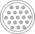
[063] Fig. 3 a shows the specific design example according to the cross section of the multi-core fiber of the 3rd embodiment.It comprises that cladding diameter is the optical fibre rod of 330um and the equidistant array of 19 monomode fibers.The optical fiber external diameter is 400 μ m in this example.The core diameter of each independent fibre core is that 30um and core to core spacing are 60um.Can realize different core design, promptly, traditional step index optical fiber design, microstructured optical fibers (people's such as L.Michaille ' Phase locking and supermode selection in multicore photonic crystal fiber lasers with a large doped area ', Opt.Lett., vol.30, pp.1668 (2005)), and leakage path optical fiber (people's such as Dong U. S. application sequence number 11/134,856) and Prague (Bragg) optical fiber.All these optical fiber designs are known in the art, and further are not described at this.In all these designs, doping Yb (or another rare earth dopant) can be easy to implement in core region, amplifies to realize signal.Can also implement to be used for the thin low-refraction clad material of pumping guiding.The combination fibre core area of this optical fiber is about 13400 μ m
2And than the maximum possible fibre core area of traditional large core fiber larger about 3 times.Clad area ratio reaches 6.4; Therefore described structure can obtain very high covering absorption, the useful life that this has simplified the manufacturing of this structure greatly and has prolonged optical fiber under low Yb doped level.
[064] Fig. 3 b shows the example in cross section that has the multi-core fiber of 19 independent fiber core with single-mold based on leakage path optical fiber.Here, the shade coil is represented core region, and described core region is mixed with Yb, and airport or glassy zone that the representative of little shadow-free coil has the refractive index that reduces.People's disclosed design considerationss of U. S. application of pending trial at the same time such as Dong are followed in design with each independent fibre core of corresponding leakage path, described U. S. application is: sequence number 11/134,856, sequence number 60/975,478, sequence number 61/086,433 and PCT international application no PCT/US/74668, the denomination of invention of each is " Glass Large-Core Optical Fibers (glass large-core optical fibers) ", and transfers assignee of the present invention.Sequence number 11/134,856,60/975,478,61/086,433 and the disclosure of PCT/US/74668 this in full form be incorporated into this paper and quote.
[065] selects pore size or have the area size of the refractive index that reduces, the higher loss of high-rder mode is provided simultaneously so that the loss accepted of basic mode is provided.In the exemplary embodiment, an ancient unit of weight equal to 20 or 24 *taels of silver of the refractive index of the refractive index close match fused silica glass rod that mixes piles up by hexagon and the second type rod, and the described second type rod can have identical diameter, thus each an ancient unit of weight equal to 20 or 24 *taels of silver mix excellent by 6 second type rods around.An an ancient unit of weight equal to 20 or 24 *taels of silver mix rod can have be melted quartz glass around an ancient unit of weight equal to 20 or 24 *taels of silver Doping Center part.The second type rod has the core than low-refraction, and for example, fluorine mixes quartzy, also be melted quartz glass around.The ratio of (an ancient unit of weight equal to 20 or 24 *taels of silver element rod diameter)/(second type rod diameter) is usually between 0.6 and 0.9.In the stacked common insertion quartz glass tube of hexagon, the internal diameter of described quartz glass tube is a bit larger tham the stacked external diameter of hexagon.In one embodiment, resulting prefabricated component is drawn into suitable fibre diameter on fiber drawing tower, and the inside of its middle external tube is evacuated.Polymer coating than low-refraction can also be set, so that pump light can be in the glassy zone guiding of optical fiber on optical fiber.Pumping in another embodiment, between stacked and quartz ampoule, capillary fringe is set, so that can guide in the pore layer.In another alternative embodiment, capillary can be used for replacing having the second leg type of fluorine Doping Center part.In another embodiment, boron doped quartz pushrod can be used in the structure shown in Fig. 3 c, so that make each leakage path fibre core birefringence for protecting to use partially.Described guarantor partially, the example of multicore, leakage path structure will be further elucidated hereinbelow.
[066] compare with traditional step index multicore single mode optical fiber, use multicore leakage path optical fiber to allow the more fibre core of dense arrangement, have littler Mode Coupling, this is minimizing owing to the mode wing of each independent pattern.This further illustrates in Fig. 4, and wherein the distribution of the modal intensity of conventional single mode fiber compares with the intensity distributions of leakage path optical fiber.Obviously, the wing of the intensity distributions of leakage path optical fiber is reduced to zero faster than traditional step index optical fiber.
[067] in the example shown in Fig. 3 b and the 3c, between two adjacent rear-earth-doped core region, is provided with a low-refraction structure.In order further to reduce Mode Coupling, can increase fibre core and separate and low-refraction structure more than one can be set between two doped core zones.
[068] by leakage path optical fiber, the core diameter/fibre core that can obtain to have minimum coupling between the independent fibre core is separated than~0.5.When all emission patterns of the described multi-core fiber based on leakage path of coherent superposition, can obtain the Si Telieer ratio>0.4 of far-field emission pattern at the tiling aperture structure, and not need to use any Coherence Mode modified elements (modifying element) as phase-plate.Here, we remember that Si Telieer is the ratio with the PHASE DISTRIBUTION on far field intensity and the far field intensity of hard-edge aperture light beam in the hole of light beam of a certain intensity than (Strehl ratio).Utilize filled aperature structure described below can obtain near consistent Si Telieer ratio.Even in the filled aperature structure, the independent fibre core of dense arrangement is useful in the multi-core fiber, has improved heat radiation because it makes whole fibre diameter minimize and compares with the optical fiber with big external diameter.
[069] fibre core of any dense arrangement causes the formation of super model and the Mode Coupling between the fibre core in the multicore structure.By different physical mechanisms (for example stress or built-in variations in refractive index), may cause the inherent refractive index fluctuation in the multicore structure.As a result, can suppress super model greatly.Pattern in the optical fiber can be represented as the simple linear combination of each fibre core pattern, and can ignore the Mode Coupling between the pattern.
[070] for Mode Coupling can be left in the basket, the energy coupling between the preferred fiber array element is less than about 1%, and is more preferably less than 0.1%, or less than 0.02%.In inventor's a experiment, observe about 0.01% coupling.
[071] the super model inhibition is the most effective for large core fiber, and core diameter is>30 μ m here.Compare (wherein refractive index fluctuation limits obtainable mode size) with each large core fiber, refractive index fluctuation is actually useful in the multimode fiber, because the fibre core that they allow to increase piles up density (stacking density) and compares bigger effective mode zone with each large core fiber.
[072] can also make multicore optical fiber laser with inclined to one side (PM) structure of all risk insurance.The exemplary design of multicore PM optical fiber is shown in Fig. 3 c.Here show leakage path optical fiber.Structure shown in described optical fiber and Fig. 3 b is closely similar, produces the zone but be incorporated into stress in addition, and described zone is represented by the little shadow region that is oppositely arranged with each fibre core among Fig. 3 c.In this example, it is corresponding directly around two in six structures of each fibre core that stress produces the zone.Described zone produces stress and causes protecting inclined to one side work in fibre core.The single core PM of PM leakage path optical fiber has discussion in following document: people's such as Dong U. S. application sequence number 11/134,856; U.S. Provisional Application 60/975,478; Sequence number 61/086,433; With PCT international application no PCT/US/74668, the denomination of invention of each is " Glass Large-Core Optical Fibers ".Multicore PM leakage path optical fiber designs is protected inclined to one side embodiment with these and is transferred to multicore and therefore further discussion no longer here in proportion.
[073] multi-core fiber can also be carried out profile pump as shown in Figure 5, and Fig. 5 shows the profile pump structure 300 of multi-core fiber 301.Multi-core fiber array 301 comprises than the major diameter solid glass rod.V-shaped groove 302 and optional 303 is subsequently by the side of incision multi-core fiber.Multi-core fiber comprises each fibre core 304-306; The fibre core that only shows three fibre cores but bigger quantity is possible.V-shaped groove 302 and 303 is used to guide pump light to enter the multi-core fiber structure, and wherein pump light indicates with arrow 307 and 308.This pump scheme is very similar in the following document for the described scheme of single-core fiber, described document is: name is called ' United States Patent (USP) 5 of Method for coupling light into cladding-pumped fiber sources using embedded mirror ', 854,865, be called with name ' United States Patent (USP) 6 of Method and apparatus for side pumping a fiber ', 704,479.Pumping is known for single-core fiber with various other pumping configurations for these, and therefore is not described further herein.Fig. 5 a example as the profile pump scheme; Can also use in principle in conjunction with the used any profile pump scheme of single core doubly clad optical fiber.
[074] be the Yb glass multi-core fiber of 1m for length, power output is that the calculation of Heat Load of 1kW is about 50-100W, and it produces about 10 ℃ temperature difference conversely between central authorities and peripheral core region.Therefore at the corresponding path length difference between central authorities and the peripheral fibre core under the full heat load is about 110 μ m, the time delay of corresponding 0.3ps.For the ns length pulse near bandwidth limit, this time delay does not need compensation, as long as be far longer than about 1ps coherence time.For fs or warble by force ps and ns pulse, the path length difference that heat causes needs compensation.This can realize by introduced suitable phase delay before or after optical fiber.Described phase delay is passable, for example realizes by the optical phase plate of a certain thickness.For little heat load, the adaptive optics compensation scheme can be regulated path length difference.
[075] in addition, fibre core can be positioned on the single ring that optical fiber periphery (outer rim) locates, as Fig. 5 a example shown.In different embodiment, all fibre cores have spaced radial distance roughly the same and fiber optic hub, and the path length difference that the heat between all fibre cores causes about equally.We are called coaxial multi-core fiber with this kind structure hereinafter.In addition, all fibre cores are arranged on make on the outer rim of coaxial multi-core fiber that coaxial multi-core fiber can more effective cooling and work under the absorption level of the stress fracture limit that exceeds the traditional glass rod.Reason is, compares with the traditional glass rod of identical heat load/every meter, raises obviously lower for the temperature of identical heat load at the center of coaxial multi-core fiber.In order to work under very large heat load level, it is useful therefore pump light also being limited on the ring of optical fiber periphery.This can be for example by using low-index material (for example fluoride glass) to realize to the center fiber area.The coaxial multi-core fiber of various deformation is feasible, and wherein fibre core is symmetrical arranged around fiber optic hub.In certain embodiments, fibre core can be arranged on the summit of regular polygon, for example has 6,8,12 or more polygon polygon.Structure can and may comprise airport or light around each fibre core setting.Can adopt in certain embodiments and be similar to the inclined to one side structure of the guarantor shown in Fig. 3 c.
[076] Fig. 6 a shows the exemplary embodiment that is used for carrying out at all each fibre cores the multi-core optical fiber amplifier of the 4th embodiment in the device 400 of locking phase control.Here, the multi-core fiber of use shown in Fig. 3 a and 3b.In a basic embodiment, the front end that comes from the nearly diffraction limited beam of optics of seed laser (laser seeder) 401 reflects on the front end face of multi-core optical fiber amplifier 403 via phase-plate 402 (or diffraction optical element).The single beam type that phase mask plate 402 is used for coming from seed laser converts the multiple beam type to and the light of front end system is concentrated to the position of each independent fibre core of multicore amplifier on the surface of multi-core fiber 403.In this example, the part of seed light is directed to the detector array 407 that is used for phase-detection by beam splitter (BS) 404,406 and mirror 405.In principle, can also implement to have corresponding multiple beam type more than one seed laser.Can steady operation in order to make light beam be sent to the multicore amplifier via phase-plate from seed, any a plurality of seed light beams need be concerned with.The system that realizes by a plurality of seed light beams is the direct expansion of Fig. 6 a, no longer further discusses at this.
[077], inserts the isolator (not shown) in seed (laser) device 401 backs usually for fear of feedback from the multicore amplifier.Be exaggerated in seed (laser) device light 401 each independent fibre core in the multipass amplifier, comprising any polarization drift that round trip (bilateral) structure is used to that signal gain is maximized and compensation assembly is interior of faraday (Faraday) revolving mirror.
[078] shows the end pumping structure in this example.The pump light of pump laser 409 provides via dichroic beamsplitter 410 that is inserted in the signal transmitting terminal and polarization beam splitter 411.Here, suppose that pumping and seed light have opposite polarization state.Suitable optics (device) upstream of dichroic beamsplitter also is used to make the coupling efficiency maximization of pumping and signal beams.Pumping can obtain (referring to people's such as for example Fermann United States Patent (USP) 6,778,732 and list of references thereof) from the beam-shaping semiconductor laser easily and be coupled to the pumping covering of multi-core fiber.In addition, can implement the described profile pump scheme in conjunction with Fig. 5, it has further simplified assembly.Similarly, when being incorporated into integrated component and replacing a large amount of optics in the present embodiment, further simplified assembly.
[079] after for the first time by multi-core fiber, inserts self adaptation mirror or self adaptation lens array 412 to modulate and to control the phase place that slowly changes between each fibre core.Lens array can for example be made of piezoelectric transducer and MEMs array.Also have lens to 413,414, so that the output of multi-core fiber 403 is reflected on the lens array 412.The output of multi-core fiber rod 403 is directed on the second phase-plate (not shown) similar to first phase-plate 402 via polarization beam splitter 411, and it is synthetic and be directed at application subsequently to be used for light beam.A fraction of output beam is directed on the detector array 407 via beam splitter 406.Output by a part of seed signal and a part of multi-core fiber 403 is interfered, and can obtain the phase information corresponding to the light path of each independent fibre core in the multi-core fiber.
[080] signal of seed laser may be stretched by chromatic dispersion in good time and may comprise the peak power of other big chromatic dispersion quantity pulse compression element with further increase pulse.
[081] example of commercial self adaptation lens array has been shown among Fig. 7.For design good lens array, the position of each mirror can be adjusted between the frequency of 100-1000Hz, this is enough to compensate the slow phase fluctuation in the multi-core fiber array, in case optical fiber is worked under steady temperature, described phase fluctuation has maximum amplitude in the bandwidth of 1-100Hz scope.
[082] in different embodiment, the commercial MEMs device with array of the mirror of spatially separating can be used for phase control.Each element of MEMs array can comprise may command along the mirror on several microns length of optical axis (haul distance), and inclination (tip/tilt) control can be provided.For instance, can comprise the MEMs deformable mirror from the S37 series that Iris AO company obtains, comprise the array with 37 elements, range is 12 μ m, and may command has Control Software up to about 2KHz.
[083] in different embodiment, utilize the known standard technique of astronomy to carry out required self adaptation mirror electronic driver control, that is, each mirror is applied a little dither signal and the heterodyne of utilization under chattering frequency and detect the phase place of measuring along the optical signal path of this arm.
[084] by this multi-core fiber array, the power limit that can surpass conventional single mode fiber reaches the magnitude of 10-100, and wherein the average power capacity can be in the kW scope.
[085] the particular design example that comprises the 4th embodiment of the optical texture 500 that is used for coherent superposition is further discussed at Fig. 6 b.For simplicity, we suppose that multi-core fiber 501 is the inclined to one side with the guarantor of profile pump.The output (not shown) of monomode fiber amplifies by suitable telescope (telescope) (also not shown), is the input beam 502 of 100 μ m so that produce spot diameter on a plane of PO position 503.At wavelength is that therefore corresponding angular divergence is 0.73 degree and the numerical aperture of corresponding input beam is 0.0064 under the 1 μ m.Focal length is that the first lens L1 504 of 100mm is used to make the beam collimation from a PO subsequently.Phase-plate 505 is arranged on and the position of lens 504 apart from 100mm, so that input beam is divided into a plurality of diffracted beams.Spot diameter on the phase-plate is calculated as 1.3mm by the divergence of input beam.By the modulation period that is chosen on the phase-plate be d=0.4mm, the angle of diffraction that we obtain is sin (α)=1/400=0.0025.By phase-plate being arranged on the focal length of the second lens L2 506 that focal length is 40mm, single light beam is transformed into beam array, and wherein spot diameter is 40 μ m, and light beam is to the 100 μ m that are spaced apart of light beam.
[086] be designed for the suitable multi-core fiber 501 that receives input beam can be core diameter be 50 μ m and core to core be spaced apart 100 μ m loss passage optical fiber (for example: the multi-core fiber of leakage path optical fiber or another different designs).Identical structure also can be carried out reverse operation, and the output of multi-core fiber is synthesized single light beam, and wherein lens L1504 can be omitted.Equally, optical texture shown in Fig. 6 b of reverse operation also can be used for utilizing single only synthetic by the light beam in the filled aperature structure of multi-core fiber array 501.The technology that is used for controlling the phase place of each independent fibre core of one way (single-pass) structure will be discussed in conjunction with Fig. 8 hereinafter.
[087] multi-core optical fiber amplifier 501 and seed light beam can be isolated by the isolator that utilizes some P0 upstream.In addition, when with round trip (bilateral) arrangement works, can extract output by the upstream that faraday's (Faraday) circulator and polarization beam splitter is arranged on a P0.Described optical element is known in the art, no longer further discusses at this.
[088] in the structure shown in Fig. 6 b, second far-end of multi-core fiber is reflected on the lens array, array for example shown in Figure 7.Because each face of lens array is the magnitude of mm at diameter usually, can implement suitable amplification optics, so that on lens array, increase the interval of each light pencil of multi-core fiber.The optics that is used for the mirror image amplification is known in the art, no longer further discusses at this.
[089] in the distortion of the 4th embodiment, except round trip (bilateral) structure, can also implement one way (single-pass) structure.But, one way (single-pass) structure more complicated slightly and automatically any polarization drift in the pair amplifier compensate.Therefore, for one way (single-pass) structure, it is suitable using the guarantor's core fibre array on the high side shown in Fig. 3 c.Utilize exemplary one way (single-pass) structure 600 of protecting core fibre 601 on the high side shown in Figure 8.Here, show dimensionally the multi-core fiber preamplifier 602 with final power amplifier 601 couplings, described preamplifier is used for spatially preparing in advance signal beams, so as with the output Best Coupling of lens array to final power amplifier.Equally, use the profile pump scheme further to simplify optical module.The taper multi-core fiber that has the single beam input by usefulness as shown in Figure 9 replaces the preamplifier multi-core fiber, further simplified optical construction.Here, multi-core fiber 700 is apered to minor diameter at signal input part 701.Described multi-core fiber is equal to star-type coupler, input signal is divided into about equally each all independent fibre cores in the extended area of optical fiber.Another coupler of upstream, conical fiber zone also can be used for providing reference signal for detector array.In addition, the lens array among Fig. 8 603 can replenish in order to the spatial beam modulator of transmission (transmission) work or replace.The spatial beam modulator, for example spatial light modulator (SLM) can for example be inserted between preamplifier 602 and the power amplifier 601.Described spatial light modulator is known in the present technique field, no longer further discusses at this.Assembly shown in Figure 8 has been simplified in the use of described spatial modulator greatly.The phase-plate (not shown) can be inserted in output place of multi-core optical fiber amplifier, is used to make the Si Telieer of output beam to maximize than (Strehl ratio).
[090] interference of the output of reference signal and multi-core fiber 601 also can be used for providing feedback to spatial light modulator, to produce the hope interference pattern corresponding to all same-phase fibre cores.Desirable interference pattern can be determined by genetic algorithm.For the suitable cost function that obtains to feed back, can calculate the difference between hope and the actual interference pattern to spatial light modulator.For phase control faster, can implement Digital Holography.The principle of digital hologram is disclosed in people's such as people's such as Stappaerts United States Patent (USP) 5,378,888 and C.Bellanger ' Coherent fiber combining by digital holography ', Opt.Lett., vol.33, no.24, pp.2937 is among the Dec.2008.In order to realize being used for the digital hologram of phase control, a little test beams needs oppositely to pass through the multi-core fiber array and interfere with reference beam on another detector array (not shown).This can be by suitable arrangement beam splitter, mirror and/or other optical element so that spatially cut apart or lead beam is realized.Main beam is configured to pass through as in the previous spatial light modulator.By will test and reference beam between interference pattern feed back to spatial light modulator, described spatial light modulator can be provided in subsequently main beam by the time produce complex conjugate interference pattern.Therefore, the phase fluctuation in the multi-core fiber array can be compensated.In order to make phase compensation technical work ground best, test beams can have similar wavelength with main beam.Preferably, test beams have little spectral bandwidth and the wavelength that has placed in the middle in the spectral bandwidth of main beam.Digital Holography is compatible with any fiber phase array structure discussed in this article.Digital Holography is being known in the art, and therefore no longer further discusses at this.Because in the phase fluctuation of multi-core fiber array medium and low frequency, it is very effective that Digital Holography compensates phase fluctuation in described structure.
[091] in the 5th embodiment, several other the scheme of can implementing is used for phase-detection.
[092] Figure 10 shows a preferred embodiment.Utilize phase-plate to do diffraction element 801 and relay lens 802 and 803, pulse seed " signal " light source 800 is reflected on the fibre core of multicore amplifier optical fiber 806.At fiber end face, utilize relay lens 804 and 805 that fibre core is reflected on the segmented mirror array, make the light that sends from single core pass through single mirror part (mirror joint) fibre core that reflected back is identical.Each mirror part (mirror joint) can be by the driver translation parallel with optical propagation direction.Faraday (Faraday) circulator is round trip (bilateral), to guarantee to resist the environmental stability of polarization rotation in the amplifier optical fiber fibre core.Oppositely by after the amplifier fibre core, light is polarized beam splitter 809 to be separated from emission light for the second time.Multicore amplifier optical fiber 806 carries out cladding pumping by pumping source 810.
[093] fibre core of the narrow linewidth continuous wave light of " stablizing " laser 811 by each doping is by co-propagate and be used for phase-detection.The wavelength of light source is chosen to be high transmission (transmission) property that has by optical fiber.Preferably, select the wavelength of continuous wave light source to be different from the signal wavelength of seed source 800 and outside the maximum gain bandwidth of amplifier fibre core.This has guaranteed almost do not have or do not obtain gain and cw (continuous wave) light obviously not exhaust amplifier gain by co-propagate cw (continuous wave) light.Preferably, the wavelength of the cw of selection (continuous wave) the light source approach signal wavelength of trying one's best, so that be not subjected to the aberration of relay lens 803,804 and 805, thus and the angle of diffraction of the angle of diffraction approach signal wavelength at diffraction element 801 places.
[094] part of the glistening light of waves is walked around Active Optical Fiber and is used as reference beam continuously.This part utilizes acousto-optic modulator (AOM) 812 to pass through the frequency of local oscillator 813 by the element of shift frequency and irradiates light detector array.Combine with flashlight at beam splitter 814 places with cw (continuous wave) light of flashlight co-propagate.Lens 816 are used from together with lens 803 1 each fibre core are reflected on the single photodiode of photodiode array 817.If the wavelength of continuous-wave laser is different with seed laser, the optical bandpass filter for example coating on interference light filter (IF) 815 and the beam splitter 814 can be used for stoping the light outside the continuous-wave laser wavelength to be full of detector.
[095], detects the continuous glistening light of waves of co-propagate and the reference light of flashlight interference and heterodyne beat signal in detector array element.Can insert optics ripple plate, diffraction element and other lens in the reference beam, so that the Beat Signal maximization.Any variation of the optical path length of Active Optical Fiber fibre core causes Doppler (Doppler) frequency displacement of the continuous glistening light of waves of co-propagate and therefore causes the frequency displacement of Beat Signal.Therefore this Beat Signal can be used for the optical path length of all fibre cores is stabilized in steady state value.This method is generally used in conjunction with the CW laser and is disclosed in for example people's such as S.J.Augst Opt.Lett.29, in 474 (2004).Among the described here embodiment, but continuous-wave laser is that to be used for the optical path length of each independent fibre core stable and be different from the light of amplification.Present embodiment can be used for all repetition rates of seed source.Stable for optical path length, heterodyne signal optionally filters by bandpass optical filter 818.Phase detectors (PD) 820 are used to detect the relative phase between heterodyne beat signal and the reference oscillator.Described phase detectors provide error signal for the feedback stability loop, and described feedback stability loop is by loop filter 821 closures of control mirror driver.The optics prescalar (pre-scaler, PS) 819,16 frequency dividing circuits for example can be used for increasing the lock-in range of feedback control loop.
[096] feedback control loop is dynamically determined by the frequency response of loop filter and driver element.The fastest response time of loop filter and driver is that this obviously is longer than seed pulse length on 10 μ s time-quantum methods.Therefore, the fast phase in the continuous wave laser changes, and for example the cross-phase modulation owing to continuous wave laser and amplifying signal light takes place, not interferometric phase Compensation Feedback loop.
[097] in second embodiment of phase-detection, itself can be used as reference seed light, shown in Figure 10 b.Will be high enough to allow heterodyne detection efficiently because the frequency of local oscillator need be lower than pulse repetition frequency, present embodiment is preferred for the situation that pulse repetition frequency is higher than 1MHz.For low frequency, can be based on the phase detectors of RF frequency mixer from analog to digital quantizer (ADC) and digital signal processor replacement.Here, the frequency bandwidth of feedback control loop preferably is chosen to be less than 1/10th of pulse repetition frequency.
[098] Figure 11 shows another embodiment of phase-detection under low-repetition-frequency.Here, high repetition frequency (>10MHz) mode locking oscillator 900 is used as seed source.Acousto-optic modulator 902 is used to modulate the intensity of the light pulse of seed laser.This propagates resulting first order diffraction beam and carries out by modulator 902 being applied radio frequency (RF) driving frequency and optical system being set.Zeroth order non-diffracted beam (not shown) is blocked so that stop energy to be propagated by optical system.In the design of these technology through being usually used in acousto-optic modulator and deflector system, no longer further discuss at this.Utilize RF reference oscillator 904 and have RF (radio frequency) Driving Field of the RF amplifier 903 generation modulators of the input that is used for amplitude modulation(PAM).Radio frequency amplifier is modulation in the following manner now: high-power RF pulse under the repetition rate that significantly is lower than the locked mode optical oscillato, generates but with each n rank oscillator pulses synchronously and obviously lower but be not zero At All Other Times.By this way, the optical pulse string is modulated in the following manner: each n rank pulse has high strength and but other pulse has obviously low the intensity of non-zero.This makes and detects the pulse train that can use the diffraction of frequency displacement under the oscillator repetition rate for heterodyne beat that wherein the part of oscillator light is by beam splitter 901 samplings.Two intensity are selected in the following manner: the amplifier energy of storage is mainly exhausted by the high strength seed pulse and the intensity contrast between amplifier output place height and low-intensity pulse is tangible.In order to prevent that the phase-detection electronic device is full of by high intensity light pulses, can provide restricting circuits or high-speed electronic switch.Here, the frequency bandwidth of feedback control loop preferably is chosen to be than high ten times of pulse repetition frequencys.
[099] in the 3rd embodiment of the phase-detection shown in Figure 10 c, the little modulation of originating from local oscillator or dither signal are applied on each element of mirror driver array.Signal from detector array is a phase-sensitive detection.After low-pass filtering, phase error and ditty system signal node merge as the feedback signal to drive array.The cut-off frequency of low pass filter is lower than chattering frequency.
[100] in the 4th embodiment of the phase-detection shown in Figure 10 d, reference beam does not have the pulse repetition frequency of skew and seed to be used as local oscillator on wavelength.This method is utilized the frequency comb structure of seed laser and is disclosed in detail among people's such as Yi-Fei Chen " the Remote distribution of a mode-locked pulse train with sub 40-as jitter ".But, the only stable optical path length that not have single fiber that gains of the described achievement in research of people such as Chen.In the embodiment of Figure 10 d, a plurality of optical fiber are stabilized to equal optical path length and have optical gain.
[101] in the 5th embodiment of the phase-detection shown in Figure 10 e, detector array is replaced by the array of the cross-correlator of interferometry.Detect the interference pattern of interferometry signal and implement low bandwidth feedback stability based on software.In an improvement of present embodiment, the signal that comes from an active fibre core is used as reference beam.
[102] many combinations of the distortion of above-mentioned example embodiment are feasible.
[103] as the replacement of the interference pattern that the cross-correlator by interferometry is generated, the interference pattern that the spectrum between amplifying signal pulse and the reference beam is interfered also can be used for feedback stability.
[104] in certain embodiments, as to the substituting of the heterodyne Detection Technique that is used for phase control, can also implement hereditary adaptive optics algorithm, so that the wavefront error of multi-core fiber array is minimized.Because genetic algorithm detects slowly manyly than heterodyne usually, described algorithm is applicable to heat-flash coupling multicore optical fiber.In certain embodiments, optimized Algorithm and specialized hardware can provide the control bandwidth of increase for system according to genetic algorithm.The needs to the interferometric detection of phase front and reference arm have been eliminated in the use of genetic algorithm.Therefore the multi-core optical fiber amplifier that is used for the genetic algorithm of phase control based on use is configured to be very similar to the design shown in Fig. 6 a, has wherein removed reference arm.In order to obtain to feed back to the suitable cost function of lens array, the part of output beam has been used doubler.The power of frequency multiplication can be measured and suitable adiabatic adjustment the by lens array is optimized by single detector subsequently.In addition, can implement detector array, at several position sampling frequency multiplication light beams; Suitable cost function makes the maximizes power of central light beam part subsequently and makes the minimum power of the peripheral part of light beam.Obviously, based on the side-coupled multicore amplifier with self adaptation mode control of genetic algorithm be highly compact and do not need a lot of parts, this is desirable for commercial system.
[105] as to the substituting of multi-core fiber, more traditional fiber phase arrays also can be used for coherent superposition.Described structure is known in the art, and the system embodiment that is used for optical signalling is disclosed in the U.S. Patent Application Serial Number 11/546,998, no longer further discusses at this.Traditional fiber array can use independent pump diode to each array element, and this has increased the noise bandwidth of phase fluctuation.Therefore, it also is useful each array element being used the acousto-optic phase-modulator.Because here the phase noise bandwidth is 10-100kHz, pulse recurrence rate must not need independent continuous wave control laser so that allow phase control in the scope of 100kHz-1MHz.For than the low-repetition-frequency signal, can be used for phase modulated in conjunction with the leakage between the described pulse modulator of Figure 10 b as mentioned.
[106] in addition, be lower than the situation of 100kHz for pulse repetition frequency, the continuous wave reference signal can be used for taking into account suitable (enough) bandwidth to phase control, as explaining in conjunction with Figure 10 a.Described continuous wave laser is chosen in the wavelength (that is, for Yb amplifier be 1300nm) of high transmission (transmission) by amplifier optical fiber down and can be coupled to each array element so that the phase place of each array arm is equated.But, continuous wave laser has increased the complexity of system.
[107] owing to can control phase rise and fall by the bandwidth that increases under the situation of not using leakage signal, it is simple gradually that the coherent superposition of pulse repetition frequency>1MHz becomes.
[108], can realize the minimizing of number of elements by utilizing a pump beam when the modulator array that in coherent superposition, is used for the phase control of each beam path.This exemplary embodiment is shown in Figure 12 a and the 12b.Figure 12 a shows the assembly 1000 that is used for the coherent superposition of fiber amplifier when using a pump beam.Here, multi-core fiber 1001 is made up of the array of independent optical fiber 1002,1003,1004, in the border loosely fusion of optical fiber separately.The cutaway view of described loose fused optical fibers array is shown in Figure 12 b.Because optical fiber is loose fusion, they can be divided into independent optical fiber at the signal injection end, allow each signal beams 1005,1006,1007 to be coupled to each optical fiber, shown in Figure 12 a.In pumping coupled end 1008, optical fiber end can further be fused, to allow being operatively coupled to fiber array 1001 from the pump beam 1009 of pumping 1010 via beam splitter 1011 and lens 1012.
[109] Si Telieer of output beam can be maximized by using as the phase-plate in the filled aperature structure of being discussed in conjunction with Fig. 6 a and 6b equally than (Strehl ratio).
[110] to be based on mainly be that transmission optical component (for example lens and transmission phase plate) illustrates to the foregoing description.Different embodiment as herein described relates to the design of high-power laser system, comprises peak value and average power.Be higher than the power level of 100W, by using the reflective optical device mirror and the diffraction element of reflective operation (for example with) thermal management of can going a long way greatly.Substituting lens and substitute the transmittance diffraction element with the reflectivity diffraction element with mirror is simple and direct (understandable), no longer further discusses at this.
[111] fiber optic laser source conduct pulse as herein described, the phase dry-mate connection is used for optical parametric amplifier and is used for high-power EUV, and the pumping source that X-ray and plasma generate is desirable.Generate for EUV and X-ray, use laser induced plasma usually, wherein plasma produces on solid-state or liquid metal target by the pulse steering with coherent combination.The increase peak power of the fiber optic laser source of the pulse of coherent combination is compared the conversion efficiency of having improved EUV and the generation of X-ray greatly with single-core fiber.Use and the high-power EUV in high-resolution imaging field and X-ray source are very interesting at advanced person's imprint lithography, and high-power EUV and X-ray source can be benefited very big by implementing the source based on the high-power coherent combination optical fiber of compactness discussed in this article.
[112] U.S. Patent Application Serial Number 11,091, compact high-power parametric amplifier have been discussed in 015, no longer further discuss at this.Is very attractive with multi-core optical fiber amplifier as the enforcement of parameter pumping source because with carry out pumping with the single-core fiber amplifier and compare them and increased the pulse energy that can obtain from described system.
[113] according to the 6th embodiment, Figure 13 shows the example with the parametric amplifier 1100 of coherent combination optical-fiber laser pumping.Can use single seed oscillator 1101 here for simplicity.The seed oscillator is based on Yb's and injects multi-core optical fiber amplifier 1102 with the pumping pulse of produce power in the 10-1000mJ scope.The seed oscillator by as ' the passive frequency translation components of being discussed in 015 is carried out frequency displacement easily, so that injection parameter amplifier crystal 1103.Output by overlapping parameter seed signal and multi-core optical fiber amplifier on time domain can obtain the effective amplification in the parametric amplifier crystal.Enforcement by chirped pulse amplification scheme can further make the B integration in the multi-core optical fiber amplifier minimize.Amplify in order to implement chirped pulse, after the seed oscillator and before signal injects multicore (or multicomponent) fiber amplifier, can provide the pulse stretching level.After each light pencil coherent combination of multicore (or multicomponent) fiber amplifier, provide the pulse compression level.Described pulse compression level is for example eligibly based on a large amount of diffraction grating.After pulse compression, pumping pulse further is directed to parametric amplifier, and here they are used to amplify seed signal.By multicore (or multicomponent) fiber amplifier, the pulse energy that can generate generation surpasses the high-average power parametric amplifier of 10mJ.
[114] therefore, the inventor has described the high-peak power fiber amplifier system with at least one fiber amplifier array, and is particularly suited for the coherent combination of laser pulse.Described amplifier system can be applicable to high-peak power, short pulse is used.For example, can produce the peak power of 1MW magnitude at least.Described system can be used for EUV or the x-ray generates, optical lithography, laser radar or similarly application.
[115] at least one embodiment comprises high-peak power fiber amplifier system.Described system comprises the array of fiber amplifier.Described amplifier array is provided with as follows: the thermal fluctuation of amplifier is fully mated and limiting amplifier output place relative phase rises and falls in low bandwidth, for example less than about 10KHz.Amplifier is arranged on enough relative distance, makes that the energy coupling between any amplifier can be ignored.Described system comprises the device that is used to inject amplifier array, comprises lasing light emitter.The pulse of seed pulse and/or amplification comprises the pulse duration in femtosecond-Yue 1 microsecond scope.Beam splitter is arranged between lasing light emitter and the array distributing the pulse from described source, or distributes the pulse from the device that is used to inject.Pulse is allocated to a plurality of beam paths that incide on the corresponding array amplifier.The allocation of space of light beam is substantially similar to the allocation of space of pulse.Comprise at least one pumping source, be used for optical pumping fiber amplifier array.Be connected to the fiber amplifier of array by a plurality of phase control element optics of spatial relationship arrangement.Phase control element changes the optical phase of at least one fiber amplifier output and comes the response phase control signal.Described system also comprises the device that is used to produce a plurality of phase control signals that are applied to phase control element, so that control optical phase in output place of most of fiber amplifiers.Described control signal and phase control element are configured to stablize the optical phase between most each fiber amplifier of array.
[116] at least one embodiment comprises high-peak power fiber amplifier system, and described system comprises the array of fiber amplifier.The space interval that described array is configured to the fibre core of amplifier is small enough to provides the heat-flash coupling, and the output phase of array is risen and fallen is limited in low bandwidth, for example less than about 10Khz.Enough big space interval between the fiber amplifier has also limited the luminous energy coupling between the amplifier of array, for example is restricted to about 0.1% or littler.A plurality of phase control element are connected to the fiber amplifier of array by spatial relationship setting and optics.Phase control element changes the optical phase of at least one fiber amplifier output and comes the response phase control signal.Described system also comprises the phase controller that produces phase control signal, and can operate the optical phase with amplifier output place of stablizing array.
[117] at least one embodiment comprises the amplifier system of the coherent combination that is used for laser pulse.Described embodiment comprises the array of fiber amplifier, for example a plurality of independent fiber amplifiers, and at least one pumping source is configured to optical pumping fiber amplifier array.The master oscillator of pulse injects seed to the fiber amplifier array.Be connected to the fiber amplifier of array by optics by a plurality of phase control element of spatial relationship setting.Phase control element changes the optical phase of at least one fiber amplifier output and comes the response phase control signal.The device that is used to produce a plurality of control signals that are applied to phase control element is controlled the optical phase of output place of most of fiber amplifiers.Described control signal and phase control element are stablized the optical phase between most each independent fiber amplifier.
[118] at least one embodiment comprises the amplifier system of the coherent combination that is used for laser pulse (for example subnanosecond pulse).Described embodiment comprises the array of fiber amplifier, for example a plurality of independent fiber amplifiers, and at least one pumping source is configured to optical pumping fiber amplifier array.The master oscillator of pulse injects seed to the fiber amplifier array.The part of the output of master oscillator is used to reference arm, and is configured to a part of optical interference with the output of fiber array.Optical interference detects with detector array.Reference arm is detected with the heterodyne phase of optical phase that allows to carry out most of elements of fiber array with detector array by further phase modulated.Be connected to the fiber amplifier of array by optics by a plurality of phase control element of spatial relationship setting.Phase control element changes the optical phase of at least one fiber amplifier output and comes the response phase control signal.Optics output phase between most of individual components of heterodyne phase detector and phase control element stable fiber array.
[119] at least one embodiment comprises the amplifier system of the coherent combination that is used for laser pulse (for example subnanosecond pulse).Described embodiment comprises the array of fiber amplifier, and for example a plurality of independent fiber amplifiers and at least one pumping source, described pumping source are configured to optical pumping fiber amplifier array.The master oscillator of pulse injects seed to the fiber amplifier array.The part output of master oscillator can be used for reference arm, and is configured to export optical interference with the part of fiber array.Interfere with the detector array detection optical.The optical phase of the element of fiber amplifier array is shaken under the frequency of originating from local oscillator, and the heterodyne phase of optical phase that allows to carry out most of elements of fiber array with detector array detects.The heterodyne phase detector is configured to the optics output phase between most of individual components of stable fiber array.
[120] in different embodiment:
[121]-amplifier can be configured such that the thermal fluctuation of the refractive index of Amplifier Gain medium is fully mated and be limited in low bandwidth so that the relative phase of amplifier output place rises and falls, for example less than about 10KHz.
[122]-control signal and phase-modulator can be configured to make the Si Telieer of the output of fiber array to maximize than (Strehl ratio).
[123]-pulse repetition frequency can be greater than about 100KHz.
[124]-frequency of control signal can be less than about 1/10 pulse repetition frequency.
[125]-pulse repetition frequency can be less than about 100kHz.Control signal can be produced by leakage signal (for example between the pulse in each optical fiber of array).
[126]-amplifier array can comprise multi-core optical fiber amplifier.
[127]-amplifier array can comprise a plurality of multi-core optical fiber amplifiers.
[128]-multi-core optical fiber amplifier can comprise by step index optical fiber, leakage path optical fiber, each individual component that photonic crystal fiber or Prague (Bragg) optical fiber constitutes.
[129]-each independent fiber amplifier can be that the guarantor is inclined to one side.
[130]-phase-plate can be inserted between master oscillator and the fiber amplifier array, so that make the coupling efficiency maximization of master oscillator to each amplifier of fiber amplifier array.
[131]-can comprise the phase-plate that is inserted in amplifier array output downstream, so that make Si Telieer (Strehl) the ratio maximization of optical fiber output.
[132]-system can comprise the device that is used for the profile pump amplifier array.
[133]-amplifier can be configured to round trip (bilateral) structure, and can comprise faraday (Faraday) circulator that is inserted in after first journey.
[134]-amplifier can be configured to one way (single-pass) structure.
[135]-phase control element can form the integrated array of element, for example MEMs or SLM.
[136]-phase control element can comprise the part of lens array.
[137]-phase control element can comprise the part of MEMs array.
[138]-phase control element can comprise the part of liquid crystal spatial light beam modulator.
[139]-can comprise phase place preamplifier array, and mate on optical dimensions with amplifier array.
[140]-the preamplifier array can be tapered at its input, so that simplify the coupling of master oscillator to the preamplifier array.
[141]-the fiber amplifier array can become each individual component and in the contact of its output optics, be coupled to amplifier array so that simplify master oscillator in its input separated by spaces.
[142]-can inject optical pumping fiber amplifier array at the optics contact jaw of amplifier array with single pumping source.
[143]-system can comprise the signal reference arm, and described reference arm is configured to the part of the output beam of interference optical fiber array, so that detect the optical phase of each independent fiber amplifier output.
[144]-fixing chattering frequency can be used for controlling a plurality of phase control element, for example phase-modulator.
[145]-different chattering frequencies can be used for controlling a plurality of phase control element.
[146]-phase place of reference arm can modulate under fixed frequency.
[147]-system can comprise one or more detectors, for example detector array.
[148]-system can comprise that coupling and transmission cross the continuous wave laser of each independent fiber amplifier of array, and be arranged for the optical phase that heterodyne phase detected and stablized each fiber amplifier of array.
[149]-and control signal can be derived from genetic algorithm, and described genetic algorithm is designed to make the Si Telieer (Strehl) of output of fiber array than maximization.
[150]-the fiber amplifier array can be used for EUV or the X-ray generates.
[151]-the fiber amplifier array can be used as the light source in the optical lithography.
[152]-the fiber amplifier array can be used as the pumping source that parameter is amplified.
[153]-lasing light emitter can comprise mode locking oscillator.
[154]-system can be included in the pulse stretching level after the master oscillator, and the pulse compression level is inserted in the downstream of fiber amplifier array.
[155]-heterodyne phase detector and a plurality of phase control element can be set for the Si Telieer (Strehl) of the output that makes fiber array than maximization.
[156]-reference arm can be derived from the individual component of fiber array.
[157]-modulator array can be set for the optical phase at each amplifier of different frequency modulated.
[158]-the heterodyne phase detector can be configured to make the Si Telieer of output of fiber array than maximization.
[159]-allocation of space of one or more pulses can be nearly diffraction limit.
[160]-luminous energy coupling between the optical fiber array element can be less than about 1%.
[161]-relative relief of array element may be limited to less than about 1KHz.
[162]-device that is used to produce a plurality of control signals can comprise detector array and be used to handle the adaptive algorithm of the phase information that obtains from detector.
[163]-adaptive algorithm can comprise genetic algorithm.
[164]-device that is used for injecting (seed) can comprise the modelocked fiber oscillator.
[165]-device that is used for injecting (seed) can comprise the pulse stretcher that is used to increase from the pulsewidth of the pulse of mode-locked laser or the emission of other source.
[166]-lasing light emitter can comprise semiconductor laser diode, and can be created in the pulsewidth in psec-Yue 1 microsecond scope.
[167]-fiber array can comprise multi-core fiber.
[168]-multi-core fiber can comprise leakage path optical fiber.
[169]-leakage path optical fiber can be that the guarantor is inclined to one side.
[170]-control signal is applicable than pulse repetition frequency height ten times frequency roughly.
[171]-system can comprise the signal reference arm and be used for the device of phase compensation, be configured to interfere a part of oppositely passing through the light beam of fiber array, and allow forward to be carried out the compensation of the optical phase of each independent array element by the light beam of described fiber array by the device that is used for phase compensation.
[172]-device that is used for phase compensation comprises the spatial beam modulator, Shang Yong spatial light modulator (SLM) for example.
[173]-energy coupling between the optical fiber array element can be less than about .1%.
[174]-phase control element can be configured to modulate the phase place of described amplifier.
[175]-phase control element can comprise phase-modulator.
[176]-amplifier system can comprise multicore leakage path optical fiber (LCF).
[177]-array of amplifier can be provided with around common center and roughly be equidistant from described center.
[178]-control bandwidth of phase controller can be less than about 10KHz.
[179]-amplifier system can comprise multi-core fiber.The array of amplifier can be arranged on the single ring of nearly periphery of described multi-core fiber.
[180]-phase control element can form the part of integrated phase modulator.
[181]-the compact systems structure can obtain as a result of the low bandwidth phase fluctuation of optical fiber output.For example, phase control element can comprise MEMs, SLMs, micro mirror array, or other integrated device and/or assembly.
[182]-pulsewidth is greater than the output of the nearly diffraction limit of an about 10fs result as phase compensation, and can obtain as a result of finite module coupling between the fiber amplifier of array.
[183]-and output pulse width can be at about 100fs-1ns, 100fs-10ps, and 1ps-1ns, or in the scope of about 100ps-50ns.
[184] description of above preferred embodiment provides by the mode of example.By the disclosure that provides, the advantage that those skilled in the art not only can understand the present invention and be followed, but also can find the tangible different changes of disclosed structure and method and change.Therefore, seek to make all these changes and change to fall into and be equal in the spirit and scope of the present invention that limited by appended claims.
Claims (26)
1. high-peak power fiber amplifier system comprises:
With the fiber amplifier array that the form of multi-core fiber realizes, described fiber amplifier is spaced apart that the thermal fluctuation that is arranged so that described fiber amplifier is fully mated and is limited in bandwidth less than 10kHz and make that the luminous energy coupling between any fiber amplifier of described fiber amplifier array is negligible so that the relative phase of fiber amplifier output place risen and fallen;
Lasing light emitter, described lasing light emitter are used for injecting seed and producing the pulse of pulsewidth in the scope of femtosecond scope or 1 psec to 1 microsecond to described fiber amplifier array;
Beam splitter, described beam splitter is arranged between described lasing light emitter and the described fiber amplifier array, so that will be divided into a plurality of beam paths that incide on the corresponding array amplifier from the pulse of described lasing light emitter, wherein the allocation of space of the light beam in described path is substantially similar to the allocation of space of the output of described lasing light emitter;
At least one pumping source, described pumping source are arranged for the described fiber amplifier array of optical pumping;
A plurality of phase control element, described a plurality of phase control element is connected to the fiber amplifier of described fiber amplifier array by spatial relationship setting and optics, and described element changes the optical phase of at least one fiber amplifier output and comes the response phase control signal; With
Phase control device, described phase control device is used to produce the optical phase of described control signal with output place of the fiber amplifier of controlling most of described fiber amplifier arrays, and wherein said control signal and phase control element are stablized the optics output phase between the fiber amplifier of most of described fiber amplifier arrays.
2. high-peak power fiber amplifier according to claim 1 system, described system comprises the phase-plate in the downstream of the output that is inserted in described fiber amplifier array, so that the Si Telieer of output that makes described fiber amplifier array is than maximization.
3. high-peak power fiber amplifier according to claim 1 system, the energy coupling between the amplifier of wherein said fiber amplifier array is less than 1%.
4. high-peak power fiber amplifier according to claim 1 system, wherein said relative phase rises and falls less than 1KHz.
5. high-peak power fiber amplifier according to claim 1 system, wherein said phase control device comprises detector array and is used to handle the adaptive algorithm of the phase information that obtains from described detector.
6. high-peak power fiber amplifier according to claim 5 system, wherein said adaptive algorithm comprises genetic algorithm.
7. high-peak power fiber amplifier according to claim 1 system, wherein said lasing light emitter comprises mode-locked laser.
8. high-peak power fiber amplifier according to claim 7 system, wherein said lasing light emitter comprises pulse stretcher, described pulse stretcher is used to increase the pulsewidth from the pulse of described mode-locked laser emission.
9. high-peak power fiber amplifier according to claim 1 system, wherein said multi-core fiber comprises leakage path optical fiber.
10. high-peak power fiber amplifier according to claim 9 system, wherein said leakage path optical fiber is polarization maintaining optical fibre.
11. high-peak power fiber amplifier according to claim 1 system, described system comprises signal reference arm and phase compensator, described reference arm is configured to interfere oppositely the part by the light beam of described fiber amplifier array, so that the light beam of forward by described fiber amplifier array provided the compensation of optical phase of each independent fiber amplifier of described fiber amplifier array by described phase compensator.
12. high-peak power fiber amplifier according to claim 11 system, wherein said phase compensator comprises spatial light modulator.
13. high-peak power fiber amplifier according to claim 1 system, the energy coupling between the fiber amplifier of wherein said fiber amplifier array is less than 0.1%.
14. high-peak power fiber amplifier according to claim 1 system, wherein said fiber amplifier array is set at and is used for the system that EUV or X-ray generate.
15. high-peak power fiber amplifier according to claim 14 system, the system that wherein said EUV of being used for or X-ray generate is used as the light source of optical lithography.
16. high-peak power fiber amplifier according to claim 1 system, wherein said fiber amplifier array is arranged for the pumping source that parameter is amplified.
17. high-peak power fiber amplifier according to claim 1 system, wherein said fiber amplifier comprises each optical fiber that is made of step index optical fiber, photonic crystal fiber or bragg fiber.
18. high-peak power fiber amplifier according to claim 1 system also comprises the profile pump element that is used for amplifier array.
19. high-peak power fiber amplifier according to claim 1 system, wherein said amplifier is configured to the round trip structure.
20. high-peak power fiber amplifier according to claim 1 system, wherein phase control element comprises the part of segmented mirror array.
21. high-peak power fiber amplifier according to claim 1 system, wherein phase control element comprises the part of MEMs array.
22. a high-peak power fiber amplifier system comprises:
The fiber amplifier array of realizing with the form of multi-core fiber, the space interval of the fibre core of described fiber amplifier the output phase fluctuating that can provide described fiber amplifier array is provided is limited in the heat-flash coupling of bandwidth less than 10kHz, but is large enough to and the coupling of the optical mode between the fiber amplifier of described fiber amplifier array can be limited in 0.1% or littler;
Lasing light emitter, described lasing light emitter are used for injecting seed and producing the pulse of pulsewidth in the scope of femtosecond scope or 1 psec to 1 microsecond to described fiber amplifier array;
A plurality of phase control element, described a plurality of phase control element is connected to the fiber amplifier of described fiber amplifier array by spatial relationship setting and optics, and described element changes the optical phase of at least one fiber amplifier output and comes the response phase control signal; With
Phase controller, described phase controller generate described phase control signal and operationally stablize the optical phase of output place of the fiber amplifier of described fiber amplifier array.
23. fiber amplifier according to claim 22 system, wherein said fiber amplifier array is provided with around common center and the described center of distance is roughly equidistant.
24. fiber amplifier according to claim 22 system, the control bandwidth of wherein said phase controller is less than 10KHz.
25. fiber amplifier according to claim 22 system, wherein said fiber amplifier array is set on the single ring and the common center of distance is roughly equidistant.
26. fiber amplifier according to claim 22 system, wherein said phase control element forms the part of integrated phase modulator.
Applications Claiming Priority (3)
| Application Number | Priority Date | Filing Date | Title |
|---|---|---|---|
| US2695208P | 2008-02-07 | 2008-02-07 | |
| US61/026,952 | 2008-02-07 | ||
| PCT/US2009/033051 WO2009100113A1 (en) | 2008-02-07 | 2009-02-04 | High power parallel fiber arrays |
Publications (2)
| Publication Number | Publication Date |
|---|---|
| CN101939880A CN101939880A (en) | 2011-01-05 |
| CN101939880B true CN101939880B (en) | 2013-07-24 |
Family
ID=40938648
Family Applications (1)
| Application Number | Title | Priority Date | Filing Date |
|---|---|---|---|
| CN2009801046565A Expired - Fee Related CN101939880B (en) | 2008-02-07 | 2009-02-04 | High power parallel fiber arrays |
Country Status (5)
| Country | Link |
|---|---|
| US (5) | US8199398B2 (en) |
| EP (1) | EP2248233B1 (en) |
| JP (1) | JP5600601B2 (en) |
| CN (1) | CN101939880B (en) |
| WO (1) | WO2009100113A1 (en) |
Families Citing this family (89)
| Publication number | Priority date | Publication date | Assignee | Title |
|---|---|---|---|---|
| EP1812823A4 (en) | 2004-03-25 | 2009-08-05 | Imra America Inc | Optical parametric amplification, optical parametric generation, and optical pumping in optical fibers systems |
| US7809222B2 (en) * | 2005-10-17 | 2010-10-05 | Imra America, Inc. | Laser based frequency standards and their applications |
| US7519253B2 (en) | 2005-11-18 | 2009-04-14 | Omni Sciences, Inc. | Broadband or mid-infrared fiber light sources |
| US8970947B2 (en) | 2007-09-26 | 2015-03-03 | Imra America, Inc. | Auto-cladded multi-core optical fibers |
| US8023538B2 (en) * | 2008-03-27 | 2011-09-20 | Imra America, Inc. | Ultra-high power parametric amplifier system at high repetition rates |
| FR2932929B1 (en) * | 2008-06-20 | 2010-06-04 | Thales Sa | LASER DEVICE HAVING MEANS FOR PHASING A LARGE NUMBER OF COHERENT SOURCES |
| EP2347483B1 (en) | 2008-11-04 | 2017-07-19 | Massachusetts Institute of Technology | External-cavity one-dimensional multi-wavelength beam combining of two-dimensional laser elements |
| US8159737B2 (en) * | 2009-04-27 | 2012-04-17 | Phase Sensitive Innovations, Inc. | Controlling the phase of optical carriers |
| NL2004837A (en) * | 2009-07-09 | 2011-01-10 | Asml Netherlands Bv | Radiation system and lithographic apparatus. |
| US8896915B2 (en) | 2009-11-24 | 2014-11-25 | Applied Energetics | Axial walk off multi-pass amplifiers |
| US8228599B1 (en) * | 2009-12-10 | 2012-07-24 | The Boeing Company | Coherent beam combining using real time holography |
| US8614853B2 (en) * | 2010-03-09 | 2013-12-24 | Massachusetts Institute Of Technology | Two-dimensional wavelength-beam-combining of lasers using first-order grating stack |
| EP2548056B1 (en) * | 2010-03-16 | 2021-05-05 | OFS Fitel, LLC | Multicore transmission and amplifier fibers and schemes for launching pump light to amplifier cores |
| US8531761B2 (en) | 2010-05-27 | 2013-09-10 | Massachusetts Institute Of Technology | High peak power optical amplifier |
| EP2586108B1 (en) * | 2010-06-28 | 2015-01-21 | Megaopto Co., Ltd. | Laser apparatus |
| US9620928B2 (en) | 2010-07-16 | 2017-04-11 | Massachusetts Institute Of Technology | Continuous wave or ultrafast lasers |
| DE102010052950B4 (en) * | 2010-08-31 | 2020-11-05 | Friedrich-Schiller-Universität Jena | Optical amplifier arrangement |
| TWI514000B (en) * | 2010-08-31 | 2015-12-21 | Corning Inc | Mems based surveillance system and a method for using same |
| FR2964503B1 (en) | 2010-09-07 | 2014-06-20 | Centre Nat Rech Scient | METHOD AND DEVICE FOR AMPLIFYING AN OPTICAL SIGNAL |
| EP2469221A1 (en) | 2010-12-21 | 2012-06-27 | Universite Pierre Et Marie Curie - Paris 6 | Method and system for configuring a device for correcting the effect of a medium on a light signal, method, device and system for correcting said effect. |
| EP2656137B1 (en) * | 2010-12-21 | 2015-09-16 | OFS Fitel, LLC | Multicore collimator |
| US8467425B1 (en) * | 2011-02-22 | 2013-06-18 | Jefferson Science Associates, Llc | Method for generating high-energy and high repetition rate laser pulses from CW amplifiers |
| WO2012121920A2 (en) * | 2011-03-07 | 2012-09-13 | Imra America, Inc. | Optical pulse source with increased peak power |
| US8903211B2 (en) * | 2011-03-16 | 2014-12-02 | Ofs Fitel, Llc | Pump-combining systems and techniques for multicore fiber transmissions |
| JP5681022B2 (en) * | 2011-04-06 | 2015-03-04 | 浜松ホトニクス株式会社 | Laser amplifier |
| JP5356626B2 (en) * | 2011-06-16 | 2013-12-04 | 古河電気工業株式会社 | Multi-core amplification optical fiber |
| WO2013039756A1 (en) | 2011-09-14 | 2013-03-21 | Imra America, Inc. | Controllable multi-wavelength fiber laser source |
| CN102354908B (en) * | 2011-11-02 | 2012-11-21 | 浙江大学 | Method for improving output peak power of semiconductor laser unit |
| CN104220846A (en) * | 2012-03-23 | 2014-12-17 | 住友电气工业株式会社 | Interference measuring apparatus |
| US8848277B2 (en) * | 2012-05-31 | 2014-09-30 | Asml Netherlands B.V. | System and method for protecting a seed laser in an EUV light source with a Bragg AOM |
| US8786942B2 (en) * | 2012-06-13 | 2014-07-22 | Northrop Grumman Systems Corporation | Coherently phase combined, high contrast, pulsed optical fiber amplifier array |
| US8964798B2 (en) * | 2012-07-12 | 2015-02-24 | Kla-Tencor Corporation | Reducing the spectral bandwidth of lasers |
| FR2993717B1 (en) * | 2012-07-20 | 2014-07-18 | Thales Sa | POWER LASER WITH SELF-ADAPTIVE DEVICE FOR FITTING OPTICAL FIBER AMPLIFIERS |
| FR2993718B1 (en) * | 2012-07-20 | 2014-07-11 | Thales Sa | POWER LASER WITH SELF-ADAPTIVE DEVICE FOR FITTING OPTICAL FIBER AMPLIFIERS |
| US8970935B2 (en) | 2012-09-27 | 2015-03-03 | The Johns Hopkins University | High energy fiber laser modulator |
| NL2011484A (en) * | 2012-10-26 | 2014-04-29 | Asml Netherlands Bv | Lithographic apparatus. |
| JP5739855B2 (en) * | 2012-11-07 | 2015-06-24 | 株式会社フジクラ | Amplifying optical fiber and optical amplifier |
| JP5635056B2 (en) | 2012-11-07 | 2014-12-03 | 株式会社フジクラ | Amplifying optical fiber and optical amplifier |
| JP2014099453A (en) * | 2012-11-13 | 2014-05-29 | Sumitomo Electric Ind Ltd | Amplifying multi-core optical fiber and multi-core optical fiber amplifier |
| CN102981345B (en) * | 2012-11-30 | 2015-11-18 | 广东汉唐量子光电科技有限公司 | A kind of method obtaining high power broadband green glow optical frequency com |
| TWI473373B (en) * | 2012-11-30 | 2015-02-11 | Ind Tech Res Inst | The apparatus of generating pulse train with tunable spacing time |
| JP6102943B2 (en) * | 2012-12-13 | 2017-03-29 | 富士通株式会社 | Optical device |
| JPWO2014132990A1 (en) | 2013-02-26 | 2017-02-02 | 古河電気工業株式会社 | Optical fiber bundle structure, rare earth doped multicore fiber, connection structure thereof, rare earth doped multicore fiber excitation method, and multicore optical fiber amplifier |
| EP2972470B1 (en) * | 2013-03-15 | 2021-12-29 | BAE SYSTEMS plc | Directional multiband antenna |
| TWI637804B (en) * | 2013-03-15 | 2018-10-11 | 美商伊雷克托科學工業股份有限公司 | Apparatuses for phased array modulation of a laser beam and methods for phased array modulation of a laser beam |
| US10838155B2 (en) | 2013-06-14 | 2020-11-17 | Chiral Photonics, Inc. | Multichannel optical coupler |
| US11156781B2 (en) * | 2013-06-14 | 2021-10-26 | Chiral Photonics, Inc. | Passive aligning optical coupler array |
| US10914891B2 (en) * | 2013-06-14 | 2021-02-09 | Chiral Photonics, Inc. | Multichannel optical coupler |
| US11966091B2 (en) * | 2013-06-14 | 2024-04-23 | Chiral Photonics, Inc. | Multichannel optical coupler array |
| JP6104069B2 (en) * | 2013-06-19 | 2017-03-29 | 三菱重工業株式会社 | Beam combining apparatus and beam combining method |
| CN103412371B (en) * | 2013-07-29 | 2015-07-22 | 华中科技大学 | Faraday rotary mirror capable of simultaneously carrying out polarization state conversion on multiple paths of optical signals |
| US9537282B2 (en) * | 2013-09-20 | 2017-01-03 | Alcatel Lucent | System and method for a multi-mode pump in an optical amplifier |
| JP6657087B2 (en) | 2013-11-22 | 2020-03-04 | イムラ アメリカ インコーポレイテッド | Polarization and polarization maintaining leaky channel fiber |
| CN107219628B (en) | 2013-11-27 | 2020-05-01 | 奇跃公司 | Virtual and augmented reality systems and methods |
| JP6220313B2 (en) * | 2014-05-08 | 2017-10-25 | 日本電信電話株式会社 | Optical signal amplifier |
| WO2016018508A2 (en) * | 2014-06-03 | 2016-02-04 | Nikon Metrology Nv | Method for packaging optical fiber array for laser radar |
| WO2016122821A2 (en) | 2015-01-29 | 2016-08-04 | Imra America, Inc. | Laser-based modification of transparent materials |
| WO2016129155A1 (en) * | 2015-02-13 | 2016-08-18 | ソニー株式会社 | Semiconductor laser device assembly |
| US9362710B1 (en) | 2015-07-01 | 2016-06-07 | Northrop Grumman Systems Corporation | Multichannel controller |
| JP6692128B2 (en) * | 2015-07-02 | 2020-05-13 | 株式会社フジクラ | Multi-core polarization maintaining fiber |
| US10429580B2 (en) * | 2015-08-27 | 2019-10-01 | Bar-Ilan University | Multi optically-coupled channels module and related methods of computation |
| US10302463B2 (en) * | 2015-11-19 | 2019-05-28 | Corning Incorporated | Distributed fiber sensors and systems employing multicore optical fibers |
| DE102016100721B3 (en) * | 2016-01-18 | 2017-03-23 | Trumpf Scientific Lasers Gmbh + Co. Kg | Relative phase measurement for the coherent combining of laser beams |
| CN105514782B (en) * | 2016-02-06 | 2018-09-11 | 哈尔滨工业大学 | Femtosecond pulse locking phase trunking method and device based on three periodic polarized crystals |
| CN105720466B (en) * | 2016-04-29 | 2019-06-14 | 北京工业大学 | Optical fiber array amplifier |
| CN105896251B (en) * | 2016-05-20 | 2019-06-14 | 北京工业大学 | Enhance the optical fiber array amplifier of light signal strength |
| US10122471B2 (en) * | 2016-07-07 | 2018-11-06 | Lockheed Martin Corporation | Spatially dephasing local oscillator for coherent free-space optical communications |
| KR102541171B1 (en) | 2016-07-08 | 2023-06-08 | 엘지전자 주식회사 | Wireless power transmission apparatus and method the same |
| US11108275B2 (en) | 2016-07-08 | 2021-08-31 | Lg Electronics Inc. | Wireless power transmission apparatus and method therefor |
| CN107870441B (en) * | 2016-09-23 | 2020-10-16 | 中国航空制造技术研究院 | Optical fiber laser coherent synthesis method based on digital holography |
| EP3321739A1 (en) | 2016-11-11 | 2018-05-16 | ASML Netherlands B.V. | Illumination source for an inspection apparatus, inspection apparatus and inspection method |
| PL419944A1 (en) * | 2016-12-22 | 2018-07-02 | Instytut Technologii Materiałów Elektronicznych | Method for producing active fibre optic cable and the active fibre optic cable |
| CN110024239A (en) * | 2017-01-26 | 2019-07-16 | 极光先进雷射株式会社 | Laser system |
| JP2018198287A (en) * | 2017-05-24 | 2018-12-13 | 日本電信電話株式会社 | Amplifying fiber |
| CN110869825B (en) | 2017-07-12 | 2021-12-24 | 通快激光系统半导体制造有限公司 | Polarizer device and EUV radiation generating apparatus having a polarizer device |
| US10627496B2 (en) | 2017-08-24 | 2020-04-21 | Toyota Motor Engineering & Manufacturing North America, Inc. | Photonics integrated phase measurement |
| US11121519B2 (en) | 2017-12-19 | 2021-09-14 | Imra America, Inc. | Utilization of time and spatial division multiplexing in high power ultrafast optical amplifiers |
| DE102018125356A1 (en) * | 2018-10-12 | 2020-04-16 | Active Fiber Systems Gmbh | Multi-aperture laser system |
| WO2020240788A1 (en) * | 2019-05-30 | 2020-12-03 | 三菱電機株式会社 | Laser device |
| FR3097659B1 (en) * | 2019-06-21 | 2024-04-19 | Cailabs | Light source comprising at least one semiconductor chip carrying at least one diode |
| US11581696B2 (en) * | 2019-08-14 | 2023-02-14 | Open Water Internet Inc. | Multi-channel laser |
| CN112596252B (en) * | 2020-12-30 | 2023-02-24 | 南开大学 | Light beam drift compensation device without mechanical structure and implementation method thereof |
| CN112880824B (en) * | 2021-01-07 | 2022-05-10 | 中国科学院西安光学精密机械研究所 | Noise measurement and stability control method and system for CEP (continuous emission process) of ultrashort optical pulse amplification and compression system |
| US20240103213A1 (en) * | 2021-01-26 | 2024-03-28 | Ofs Fitel, Llc | Multi-core optical fiber |
| DE102021120516A1 (en) | 2021-08-06 | 2023-02-09 | Trumpf Laser Gmbh | Device and method for combining coherent laser beams |
| CN113900278A (en) * | 2021-09-30 | 2022-01-07 | 中国人民解放军国防科技大学 | All-fiber laser phase control array system and phase control method thereof |
| US11372105B1 (en) * | 2021-10-06 | 2022-06-28 | Aeva, Inc. | FMCW LIDAR using array waveguide receivers and optical frequency shifting |
| WO2023164049A1 (en) * | 2022-02-24 | 2023-08-31 | Newport Corporation | Laser amplifier utilizing multiple end pump spots and method of manufacture |
| DE102022121616A1 (en) * | 2022-08-26 | 2024-02-29 | Trumpf Laser Gmbh | Laser system and method for laser processing a workpiece |
Citations (4)
| Publication number | Priority date | Publication date | Assignee | Title |
|---|---|---|---|---|
| US5378888A (en) * | 1993-08-16 | 1995-01-03 | Northrop Grumman Corporation | Holographic system for interactive target acquisition and tracking |
| US5566196A (en) * | 1994-10-27 | 1996-10-15 | Sdl, Inc. | Multiple core fiber laser and optical amplifier |
| US6570704B2 (en) * | 2001-03-14 | 2003-05-27 | Northrop Grumman Corporation | High average power chirped pulse fiber amplifier array |
| CN1253755C (en) * | 2002-06-18 | 2006-04-26 | 日本电气株式会社 | Fibre-optic amplifier |
Family Cites Families (59)
| Publication number | Priority date | Publication date | Assignee | Title |
|---|---|---|---|---|
| FR2655435B1 (en) | 1989-12-01 | 1992-02-21 | Thomson Csf | COHERENT ADDITION DEVICE OF LASER BEAMS. |
| US5694408A (en) * | 1995-06-07 | 1997-12-02 | Mcdonnell Douglas Corporation | Fiber optic laser system and associated lasing method |
| US5854865A (en) | 1995-12-07 | 1998-12-29 | The United States Of America As Represented By The Secretary Of The Navy | Method and apparatus for side pumping an optical fiber |
| US5717516A (en) * | 1996-03-01 | 1998-02-10 | Hughes Electronics | Hybrid laser power combining and beam cleanup system using nonlinear and adaptive optical wavefront compensation |
| JPH1022555A (en) | 1996-06-28 | 1998-01-23 | Hitachi Cable Ltd | Optical fiber amplifier |
| US6234488B1 (en) * | 1997-03-05 | 2001-05-22 | Trw Inc. | Heat shrinkable boot seal and method of installation |
| JP2007516600A (en) * | 1997-03-21 | 2007-06-21 | イムラ アメリカ インコーポレイテッド | High energy fiber optic amplifier for picosecond-nanosecond pulses for advanced material processing applications |
| US6198568B1 (en) * | 1997-04-25 | 2001-03-06 | Imra America, Inc. | Use of Chirped Quasi-phase-matched materials in chirped pulse amplification systems |
| US6272155B1 (en) | 1997-06-30 | 2001-08-07 | Hoya Corporation | Fiber bundle and laser apparatus using the fiber bundle of manufacturing the same |
| JPH1123867A (en) * | 1997-06-30 | 1999-01-29 | Hoya Corp | Fiber bundle and manufacture of fiber bundle |
| US5946130A (en) | 1997-10-03 | 1999-08-31 | Mcdonnell Douglas Corporation | Optical fiber amplifier network having a coherently combined output and high-power laser amplifier containing same |
| US6031850A (en) | 1997-12-22 | 2000-02-29 | Pc Photonics Corporation | Clad pumped, eye-safe and multi-core phase-locked fiber lasers |
| US6061170A (en) * | 1998-03-16 | 2000-05-09 | Mcdonnell Douglas Corporation | Dual frequency laser amplifier array and operating method therefor |
| US6370169B1 (en) * | 1998-04-22 | 2002-04-09 | Nippon Telegraph & Telephone Corporation | Method and apparatus for controlling optical wavelength based on optical frequency pulling |
| US6366365B1 (en) * | 1998-08-26 | 2002-04-02 | Agilent Technologies, Inc. | Waveguide array-based image sensor for document scanner scan head |
| US6275512B1 (en) * | 1998-11-25 | 2001-08-14 | Imra America, Inc. | Mode-locked multimode fiber laser pulse source |
| US6366356B1 (en) * | 1999-04-01 | 2002-04-02 | Trw Inc. | High average power fiber laser system with high-speed, parallel wavefront sensor |
| JP2001044537A (en) * | 1999-07-29 | 2001-02-16 | Hoya Corp | Optical medium, manufacture thereof, laser light generator, and optical amplifier |
| US6233085B1 (en) | 1999-10-19 | 2001-05-15 | The Boeing Company | Apparatus, method, and computer program product for controlling an interferromic phased array |
| US6708003B1 (en) * | 1999-12-16 | 2004-03-16 | Northrop Grumman Corporation | Optical energy transmission system utilizing precise phase and amplitude control |
| US6400871B1 (en) * | 2000-05-19 | 2002-06-04 | Hrl Laboratories, Llc | Phase control mechanism for coherent fiber amplifier arrays |
| US6469658B2 (en) * | 2000-05-26 | 2002-10-22 | Donald E. Voss | Method for creation of planar or complex wavefronts in close proximity to a transmitter array |
| US6631019B1 (en) * | 2000-07-05 | 2003-10-07 | Sri International | Reconfigurable multichannel transmitter for dense wavelength division multiplexing (DWDM) optical communication |
| US6480327B1 (en) | 2000-09-11 | 2002-11-12 | Hrl Laboratories, Llc | High power laser system with fiber amplifiers and loop PCM |
| US6766075B1 (en) * | 2001-05-11 | 2004-07-20 | Pc Photonics Corporation | Side pumping of optical fiber systems via multiple delivery fibers |
| US6597836B2 (en) | 2001-06-20 | 2003-07-22 | The Boeing Company | Optical phased array control system |
| US6704479B2 (en) * | 2001-07-24 | 2004-03-09 | The United States Of America As Represented By The Secretary Of The Navy | Method for coupling light into cladding-pumped fiber sources using an embedded mirror |
| JP4511831B2 (en) * | 2001-08-30 | 2010-07-28 | クリスタル ファイバー アクティーゼルスカブ | High numerical aperture optical fiber, its manufacturing method and its use |
| US6809307B2 (en) * | 2001-09-28 | 2004-10-26 | Raytheon Company | System and method for effecting high-power beam control with adaptive optics in low power beam path |
| US6882781B2 (en) * | 2001-11-16 | 2005-04-19 | Hrl Laboratories, Llc | Coherent power combining of single-mode sources in waveguide fiber couplers |
| US6701049B1 (en) * | 2002-03-22 | 2004-03-02 | The United States Of America As Represented By The National Security Agency | Optical clock recovery device using non-linear optical waveguides |
| US6778732B1 (en) | 2002-06-07 | 2004-08-17 | Boston Laser, Inc. | Generation of high-power, high brightness optical beams by optical cutting and beam-shaping of diode lasers |
| US6678288B2 (en) * | 2002-06-10 | 2004-01-13 | The Boeing Company | Multi-aperture fiber laser system |
| US7502230B2 (en) * | 2002-07-08 | 2009-03-10 | Aten International Co., Ltd. | Keyboard, video and mouse (KVM) switch |
| WO2004068745A1 (en) * | 2003-01-17 | 2004-08-12 | Hrl Laboratories, Llc | An adaptive optical system compensating for phase fluctuations |
| US6813069B2 (en) * | 2003-01-24 | 2004-11-02 | The Boeing Company | Method and apparatus for controlling a fiber optic phased array utilizing frequency shifting |
| US7107795B2 (en) | 2003-02-11 | 2006-09-19 | Cheo Peter K | Method for forming high-density multicore phase-locked fiber laser array |
| US7120175B2 (en) * | 2004-01-20 | 2006-10-10 | Northrop Grumman Corporation | Scalable harmonic laser source and method |
| US7065110B2 (en) * | 2004-01-20 | 2006-06-20 | Northrop Grumman Corporation | Scalable wavelength shifted laser source and method |
| US7088743B2 (en) * | 2004-03-15 | 2006-08-08 | Northrop Grumman Corp. | Laser source comprising amplifier and adaptive wavefront/polarization driver |
| EP1812823A4 (en) * | 2004-03-25 | 2009-08-05 | Imra America Inc | Optical parametric amplification, optical parametric generation, and optical pumping in optical fibers systems |
| US7505196B2 (en) * | 2004-03-31 | 2009-03-17 | Imra America, Inc. | Method and apparatus for controlling and protecting pulsed high power fiber amplifier systems |
| TWM259170U (en) * | 2004-05-28 | 2005-03-11 | Hon Hai Prec Ind Co Ltd | A lens used in digital camera |
| JP5255838B2 (en) * | 2004-08-25 | 2013-08-07 | ケーエルエー−テンカー コーポレイション | Fiber amplifier based light source for semiconductor inspection |
| US7787729B2 (en) * | 2005-05-20 | 2010-08-31 | Imra America, Inc. | Single mode propagation in fibers and rods with large leakage channels |
| US7187492B1 (en) * | 2005-08-30 | 2007-03-06 | The United States Of America As Represented By The Secretary Of The Air Force | Self-referenced locking of optical coherence by single-detector electronic-frequency tagging |
| JP2007110089A (en) * | 2005-09-15 | 2007-04-26 | Aisin Seiki Co Ltd | Method and device for generating high power short optical pulse |
| ATE537588T1 (en) * | 2005-09-21 | 2011-12-15 | Ecole Polytech | HIGH PEAK AND HIGH AVERAGE POWER OPTICAL PULSE AMPLIFIER |
| US7809222B2 (en) * | 2005-10-17 | 2010-10-05 | Imra America, Inc. | Laser based frequency standards and their applications |
| US7221499B2 (en) * | 2005-10-19 | 2007-05-22 | Northrop Grumman Corporation | Frequency scanned array control system |
| US7440174B2 (en) * | 2006-02-24 | 2008-10-21 | Northrop Grumman Corporation | Coherent fiber diffractive optical element beam combiner |
| US7443903B2 (en) * | 2006-04-19 | 2008-10-28 | Mobius Photonics, Inc. | Laser apparatus having multiple synchronous amplifiers tied to one master oscillator |
| US8010654B2 (en) | 2006-12-21 | 2011-08-30 | International Business Machines Corporation | Method, system and program product for monitoring resources servicing a business transaction |
| US8731013B2 (en) * | 2007-01-24 | 2014-05-20 | Raytheon Company | Linear adaptive optics system in low power beam path and method |
| JP5662151B2 (en) | 2007-09-26 | 2015-01-28 | イムラ アメリカ インコーポレイテッド | Glass large core optical fiber |
| US7916762B2 (en) * | 2008-05-27 | 2011-03-29 | Lawrence Livermore National Security, Llc | Phased laser array with tailored spectral and coherence properties |
| ES2812228T3 (en) | 2009-03-13 | 2021-03-16 | Bolton Medical Inc | System for deploying an endoluminal prosthesis at a surgical site |
| US8184363B2 (en) * | 2009-08-07 | 2012-05-22 | Northrop Grumman Systems Corporation | All-fiber integrated high power coherent beam combination |
| US8643308B2 (en) | 2009-08-14 | 2014-02-04 | Once Innovations, Inc. | Spectral shift control for dimmable AC LED lighting |
-
2009
- 2009-02-04 EP EP09708385.1A patent/EP2248233B1/en not_active Not-in-force
- 2009-02-04 US US12/365,514 patent/US8199398B2/en not_active Expired - Fee Related
- 2009-02-04 JP JP2010545965A patent/JP5600601B2/en not_active Expired - Fee Related
- 2009-02-04 WO PCT/US2009/033051 patent/WO2009100113A1/en active Application Filing
- 2009-02-04 CN CN2009801046565A patent/CN101939880B/en not_active Expired - Fee Related
-
2012
- 2012-04-27 US US13/457,576 patent/US8736954B2/en active Active
-
2013
- 2013-10-08 US US14/048,177 patent/US9013786B2/en not_active Expired - Fee Related
-
2015
- 2015-03-30 US US14/672,301 patent/US9293884B2/en active Active
-
2016
- 2016-02-11 US US15/041,066 patent/US9559483B2/en not_active Expired - Fee Related
Patent Citations (4)
| Publication number | Priority date | Publication date | Assignee | Title |
|---|---|---|---|---|
| US5378888A (en) * | 1993-08-16 | 1995-01-03 | Northrop Grumman Corporation | Holographic system for interactive target acquisition and tracking |
| US5566196A (en) * | 1994-10-27 | 1996-10-15 | Sdl, Inc. | Multiple core fiber laser and optical amplifier |
| US6570704B2 (en) * | 2001-03-14 | 2003-05-27 | Northrop Grumman Corporation | High average power chirped pulse fiber amplifier array |
| CN1253755C (en) * | 2002-06-18 | 2006-04-26 | 日本电气株式会社 | Fibre-optic amplifier |
Also Published As
| Publication number | Publication date |
|---|---|
| US20120206794A1 (en) | 2012-08-16 |
| EP2248233A4 (en) | 2015-02-25 |
| EP2248233B1 (en) | 2018-04-04 |
| US9559483B2 (en) | 2017-01-31 |
| JP5600601B2 (en) | 2014-10-01 |
| JP2011512653A (en) | 2011-04-21 |
| US9293884B2 (en) | 2016-03-22 |
| US20160226209A1 (en) | 2016-08-04 |
| US20150207289A1 (en) | 2015-07-23 |
| US8199398B2 (en) | 2012-06-12 |
| US8736954B2 (en) | 2014-05-27 |
| CN101939880A (en) | 2011-01-05 |
| US9013786B2 (en) | 2015-04-21 |
| EP2248233A1 (en) | 2010-11-10 |
| WO2009100113A1 (en) | 2009-08-13 |
| US20090201575A1 (en) | 2009-08-13 |
| US20140036350A1 (en) | 2014-02-06 |
Similar Documents
| Publication | Publication Date | Title |
|---|---|---|
| CN101939880B (en) | High power parallel fiber arrays | |
| Brignon | Coherent laser beam combining | |
| JP5616714B2 (en) | All-fiber combined high-power coherent beam combining | |
| CN101854022B (en) | Passive mode-locking fiber laser with double-wavelength short pulse output | |
| US10958034B2 (en) | Narrowband depolarized fiber lasers | |
| US7724789B2 (en) | Method and apparatus for optical mode multiplexing of multimode lasers and arrays | |
| EP2945012A1 (en) | Laser device | |
| US11777272B2 (en) | Multiplexing fiber amplified waveforms | |
| EP1648056B1 (en) | Self-coherent combining technique for high power laser implementation and method | |
| Long et al. | Compact internal sensing phase locking system for coherent combining of fiber laser array | |
| He et al. | C-band switchable multi-wavelength erbium-doped fiber laser based on Mach–Zehnder interferometer employing seven-core fiber | |
| JP2021057613A (en) | Architecture for all-fiber delivery of coherently combined laser power | |
| Klenke et al. | High-power multicore fiber laser systems | |
| Zhang et al. | Generation of all-fiber femtosecond vortex laser based on NPR mode-locking and mechanical LPG | |
| Linslal et al. | Challenges in coherent beam combining of high power fiber amplifiers: a review | |
| Zhang et al. | Multiwavelength switchable fiber laser employing a DMD as tuning element and variable optical attenuator | |
| US20210194210A1 (en) | Precision light source | |
| CN110994341B (en) | Feedback enhanced polarization-maintaining erbium-doped fiber dual-wavelength random laser | |
| JP5384978B2 (en) | Optical system including optical pulse generator | |
| Feng et al. | Wavelength and pulse-number tunable ultrafast vortex fiber laser | |
| Xu et al. | Revealing the buildup of dynamic mode-switchable frequency-shifted feedback laser based on photon–phonon interaction | |
| Chen et al. | Synchronization and coherent addition of three pulsed fiber lasers by mutual injection and phase modulation | |
| Pouysegur et al. | Coherent beam combining with an ultrafast multicore Yb-doped fiber amplifier | |
| Agate et al. | Boscolo, S., SK Turitsyn and KJ Blow, All-optical passive quasi-regeneration in transoceanic 40 Gbit/s return-to-zero transmission systems with strong dispersion management 205 (2002) 277 Brown, CTA, see Agate, B. 205 (2002) 207 Buckley, E., see Canning, J. 205 (2002) 95 |
Legal Events
| Date | Code | Title | Description |
|---|---|---|---|
| C06 | Publication | ||
| PB01 | Publication | ||
| C10 | Entry into substantive examination | ||
| SE01 | Entry into force of request for substantive examination | ||
| C14 | Grant of patent or utility model | ||
| GR01 | Patent grant | ||
| CF01 | Termination of patent right due to non-payment of annual fee | ||
| CF01 | Termination of patent right due to non-payment of annual fee |
Granted publication date: 20130724 Termination date: 20180204 |