CN102006829B - Systems and methods for surgical removal of tissue - Google Patents
Systems and methods for surgical removal of tissue Download PDFInfo
- Publication number
- CN102006829B CN102006829B CN2009801083437A CN200980108343A CN102006829B CN 102006829 B CN102006829 B CN 102006829B CN 2009801083437 A CN2009801083437 A CN 2009801083437A CN 200980108343 A CN200980108343 A CN 200980108343A CN 102006829 B CN102006829 B CN 102006829B
- Authority
- CN
- China
- Prior art keywords
- suction
- inner part
- chamber
- suction socket
- hub
- Prior art date
- Legal status (The legal status is an assumption and is not a legal conclusion. Google has not performed a legal analysis and makes no representation as to the accuracy of the status listed.)
- Active
Links
Images


Classifications
-
- A—HUMAN NECESSITIES
- A61—MEDICAL OR VETERINARY SCIENCE; HYGIENE
- A61B—DIAGNOSIS; SURGERY; IDENTIFICATION
- A61B10/00—Other methods or instruments for diagnosis, e.g. instruments for taking a cell sample, for biopsy, for vaccination diagnosis; Sex determination; Ovulation-period determination; Throat striking implements
- A61B10/02—Instruments for taking cell samples or for biopsy
- A61B10/0233—Pointed or sharp biopsy instruments
- A61B10/0266—Pointed or sharp biopsy instruments means for severing sample
-
- A—HUMAN NECESSITIES
- A61—MEDICAL OR VETERINARY SCIENCE; HYGIENE
- A61B—DIAGNOSIS; SURGERY; IDENTIFICATION
- A61B17/00—Surgical instruments, devices or methods, e.g. tourniquets
- A61B17/32—Surgical cutting instruments
- A61B17/320016—Endoscopic cutting instruments, e.g. arthroscopes, resectoscopes
- A61B17/32002—Endoscopic cutting instruments, e.g. arthroscopes, resectoscopes with continuously rotating, oscillating or reciprocating cutting instruments
-
- A—HUMAN NECESSITIES
- A61—MEDICAL OR VETERINARY SCIENCE; HYGIENE
- A61M—DEVICES FOR INTRODUCING MEDIA INTO, OR ONTO, THE BODY; DEVICES FOR TRANSDUCING BODY MEDIA OR FOR TAKING MEDIA FROM THE BODY; DEVICES FOR PRODUCING OR ENDING SLEEP OR STUPOR
- A61M1/00—Suction or pumping devices for medical purposes; Devices for carrying-off, for treatment of, or for carrying-over, body-liquids; Drainage systems
- A61M1/71—Suction drainage systems
- A61M1/74—Suction control
- A61M1/742—Suction control by changing the size of a vent
-
- A—HUMAN NECESSITIES
- A61—MEDICAL OR VETERINARY SCIENCE; HYGIENE
- A61B—DIAGNOSIS; SURGERY; IDENTIFICATION
- A61B10/00—Other methods or instruments for diagnosis, e.g. instruments for taking a cell sample, for biopsy, for vaccination diagnosis; Sex determination; Ovulation-period determination; Throat striking implements
- A61B10/02—Instruments for taking cell samples or for biopsy
- A61B10/0233—Pointed or sharp biopsy instruments
- A61B10/0283—Pointed or sharp biopsy instruments with vacuum aspiration, e.g. caused by retractable plunger or by connected syringe
-
- A—HUMAN NECESSITIES
- A61—MEDICAL OR VETERINARY SCIENCE; HYGIENE
- A61B—DIAGNOSIS; SURGERY; IDENTIFICATION
- A61B90/00—Instruments, implements or accessories specially adapted for surgery or diagnosis and not covered by any of the groups A61B1/00 - A61B50/00, e.g. for luxation treatment or for protecting wound edges
- A61B90/08—Accessories or related features not otherwise provided for
- A61B2090/0801—Prevention of accidental cutting or pricking
- A61B2090/08021—Prevention of accidental cutting or pricking of the patient or his organs
-
- A—HUMAN NECESSITIES
- A61—MEDICAL OR VETERINARY SCIENCE; HYGIENE
- A61B—DIAGNOSIS; SURGERY; IDENTIFICATION
- A61B2217/00—General characteristics of surgical instruments
- A61B2217/002—Auxiliary appliance
- A61B2217/005—Auxiliary appliance with suction drainage system
Abstract
A surgical instrument (22) including a coupler (33) maintaining an inner (54) and outer (52) members to define a cutting implement (30); and an aspiration control pathway between a first port (35) exposed at an exterior of the coupler (33) and a second port (103) connectable to a source of negative pressure (24) via. a lumen (105) of the Inner member (56), wherein the aspiration control mechanism provides user control over the level of vacuum applied at the cutting tip implement via selective positioning or a finger over the first port (35).
Description
Technical field
The present invention relates to systemic treatment.More particularly, the present invention relates to for the surgical system, apparatus and the method that reduce or extract tumor tissues.
Background technology
Carry out systemic excision or minimizing for a variety of causes and to being permitted eurypalynous tissue.For example, when its nonfunction, organ can picked-off.In some cases, must excision around tumor and/or tumor.Tumor is usually with chemotherapy, radiation, surgical operation and other technologies treatment.When surgical operation is the treatment of selecting, usually utilize various surgical operating instruments, for example the cavity forms surgical operation aspirator (CUSA), or the surgical laser cutter.
It is the treatment of selecting for the cerebral tumor cerebral surgery operation that can approach.Although CUSA can also be used for the treatment of many tissues except the cerebral tumor, cerebral surgery operation provides a useful example, with some difficulties of emphasizing to occur in the surgical removal of rapid wear tissue.Operating purpose is to extract tumor tissues as much as possible.In other operations, be out the cranium art in order to extract the surgical operation that the cerebral tumor the most often implements.Generally speaking, neurosurgeon cuts scalp, head, cerebral dura mater, meninges and cortex, to expose the brain district on tumor.Then, carry out location and the excision of tumor.
When utilizing CUSA, laser scalpel or excising other cerebral surgery operation apparatuses of system such as cold steel apparatus, ultrasonic cut device and bipolar radio frequency plasma, the rapid wear tissue relevant to the human brain anatomical structure causes some concerns.As a reference, large capsules of brain trilamellar membrane or meninges cover, and this trilamellar membrane or meninges itself are surrounded by skull again.These three layers of meningess are cerebral dura mater (below skull), arachnoidea and pia mater encephali.Flow in---being called subarachnoid space---in the space of spinal fluid between arachnoidea and pia mater encephali.The very thin and rapid wear of these meningess, wherein pia mater encephali has or keeps many blood vessels relevant to brain.Due to the frangible especially character of pia mater encephali, neurosurgeon must be very careful when attempting with surgical removal of brain tumors; Can reduce main blood supply to brain to Leptomeningeal accidental damage.To also causing patient to damage such as the unnecessary damage of other healthy structures of arachnoidea or cerebral tissue (for example, cerebral cortex) and to the unnecessary damage of tremulous pulse of cranial nerve and supply brain (and brain stem).Consider these, the CUSA apparatus is sent ultrasonication to extract tissue and bone.The surgeon attempts the ultrasonic cut end is placed on destroyed tissue.But, high frequency also may occur when being encountered by the axle of apparatus cut and damage target tumor tissue on every side.And, due to the relatively large size of CUSA head, be difficult to the naked eye determine the placement of ultrasonic axle/end.Equally, because using laser scalpel, the localized heat around the line of cut neutralization also may cause histologic lesion unintentionally.
In another example, also must take care very much the rapid wear tissue such as vocal cords and esophagus when treatment tumor and/or pathological changes in trachea.For example, pathological changes or tumor must be excised and do not damaged mucosa on every side simultaneously to avoid staying scar to vocal cords.In another example, undue invasive resection organization may cause relating to the fistula of esophagus in trachea, this fistula then cause food and the suction of fluid.
According to top described, surgeon and other doctors continue to be faced with and reduce when attempting the infringement minimum of normal tissue or extract the many challenges that present during tumor and/or pathological changes.
Description of drawings
Fig. 1 is used for according to principle of the present disclosure the schematic diagram that surgical operation reduces or extract the system of tissue;
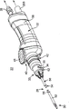
Fig. 2 is the perspective view of the surgical instruments used together with system with Fig. 1;
Fig. 3 A is the blade assembly exploded view partly of the apparatus of Fig. 1;
Fig. 3 B is the enlarged perspective of proximal end region of the interior tubular part of Fig. 3 A assembly;
Fig. 3 C is the enlarged perspective of proximal end region of the interior tubular part of Fig. 3 A assembly;
Fig. 4 A is the enlarged perspective of distal area of the outer tubular member of Fig. 3 A assembly;
Fig. 4 B is the amplification view of distal cut window of the interior tubular part of Fig. 3 A assembly;
Fig. 5 is the blade assembly of Fig. 3 A when last structure and the cutaway view of blade coupling;
Fig. 6 is the blade assembly of Fig. 3 A when last structure and the cutaway view of blade coupling;
Fig. 7 A is the blade assembly of Fig. 3 A when last structure and the perspective view of blade coupling;
Fig. 7 B is the cutaway view of the part of this apparatus when last structure;
Fig. 8 A and 8B illustrate the cutting appliance operation partly of the apparatus of Fig. 7; With
Fig. 9 A and 9B are illustrated in the application of the system of Fig. 1 in surgical removal of brain tumors.
The specific embodiment
Relate to tumor or other systemic surgical system and method for the surgical operation therapy patient according to some aspects of disclosure principle.
On the one hand, this system comprises surgical resection apparatus, motor and negative pressure source.This resection instrument comprises inner part, external part, head and suction controlling organization.This inner part comprises cutting tip far away, and external part has the distal area that forms the cutting window and at the lifting end of the distal end portion of this cutting window.This head keeps inner part and external part, makes this inner part rotatably be contained in this external part, and wherein incision tip is exposed to outside the cutting window.And incision tip and distal area make up to form cutting appliance.This motor is connected in inner part and is used for respect to external part rotation inner part, for example, and as the part of cutting operation.
On the other hand, this system comprises from cutting appliance and extends through this head to the fluid passage of negative pressure source.In some structures, this suction controlling organization is arranged in head, and in other structures, this suction controlling organization is arranged on and is configured to inner part and external part are coupled in the coupling of head.This suction controlling organization comprises the control channel that is combined in head or coupling inside, to form one section fluid passage.This suction control channel comprises the user interface port that is exposed on head or coupling outside and surrounding is opened wide.This user interface port provides putting on the control of vacuum on cutting appliance (supplying with via the remainder of fluid passage and negative pressure source) for the user.For example, by block user interface port more or lessly, the vacuum that is applied on cutting appliance increases respectively or reduces.Some optional structures in accordance with the principles of the present invention wherein, this System Construction become to make when negative pressure source produces negative pressure and user interface port and is not subjected to outer barrier, and the vacuum that is applied on cutting appliance is substantially zero.
Utilize this set, can treat various bodily tissues and/or tumor.The treatment of the cerebral tumor is described for illustrative purposes.At first the skull by patient forms opening so that the outside inlet port to cerebral tumor place therapentic part to be provided.Send cutting appliance by this opening to therapentic part.Lifting end portion ground inserts between the surrounding tissue of destination organization (for example, tumor) and this therapentic part, for example cerebral dura mater, arachnoidea, pia mater encephali and cerebral cortex one of them or a plurality of.Cutting tip is placed to tumor and contacts.Then inner part moves with respect to external part, thereby makes the tissue of cutting tip cutting tumor.At last, optionally aspirate this therapentic part, to remove tumor tissues this cutting or debridement.By utilizing the lifting end separate at least in part this tumor and optionally aspirate therapentic part, make the minimizing possibility of infringement normal surrounding tissue.Some optional aspect, method of the present invention also is included in whole operation process the vacuum level (aspiration rate) that changes at therapentic part, by applied suction before cutting operation, tumor is attracted into incision tip and contacts.
The embodiment of this system can also be used for extracing the cerebral tumor by other admission passage.For example, the inlet port that arrives brain can pass through nose, jaw, oropharynx acquisition, with treatment pituitary tumor, slope cordomas, cholesterol granuloma, neural sensation blastoma, cranium substrate meninges and meninges bulging.In another example, the embodiment of this system is used for using to treat tumor, for example acoustic neuroma by horizontal cranium substrate.
In other embodiments, treat tumor and/or the pathological changes of upper and lower respiratory tract according to principle of the present invention.The nonrestrictive example of the tumor of these types and/or pathological changes comprises tumor and/or the pathological changes that usually occurs on vocal cords, and recurrent respiratory papillary tumor, cyst, polyp, Lai Yinke edema or polypoid vocal cords spermatitis, benign tumor and malignant tumor.In another nonrestrictive example, embodiments of the invention can be used for treating tumor and/or the pathological changes in bronchus.
Said system is very useful in the surgical operation that carries out surgical oncology operation and other types.In the surgical oncology operation, this system not only can provide the ability of carrying out more accurately the excision cerebroma for neurosurgeon, and can control the suction that puts on therapentic part.
These and other aspects of the present invention are described the examples explanation in conjunction with Fig. 1-9B.
Each side is used for reducing or extracing systemic surgical system 20 being shown in Fig. 1 according to the present invention.In an example, can be used in the debridement cerebroma as a part of system 20 of cerebral surgery operation.This system 20 comprises cutter for surgical operation tool 22, negative pressure source 24 and power supply 26.The below provides the details about each parts.But in general, this surgical operating instrument 22 comprises blade assembly 28, head 32 and the integrated suction controlling organization 34 (total labelling) that forms cutting appliance 30 (total labelling).Negative pressure source 24 via extend to and fluid passage 36 fluids of housing 38 by head 32 be connected in cutting appliance 30.On the one hand, the proximal end region of head 32 also comprises suction channel 37, its partly form fluid passage 36 and by pipeline 47 fluids be connected in negative pressure source 24.At last, power supply 26 is electrically connected on the motor (being shown motor 202 in Fig. 7 B) that is kept by head 32.
Reducing with surgical operation or extracing between the operating period of tumor, cutting appliance 30 is applied to therapentic part, and wherein user is handled head 32 to obtain the position of wanting of cutting appliance 30 with respect to this cerebral tumor.Power supply 26 provides energy to carry out the tumor cutting operation at cutting appliance 30 for motor.At last, suction controlling organization 34 is by the user manual operations, optionally to aspirate with cutting appliance 30 by the vacuum that is produced by negative pressure source 24.In some structures, this suction controlling organization 34 comprises user interface port 35, and this interface port 35 can provide speed or the aspiration that changes suction and cut aggressive ability for user by enough cutting appliances 30.Consider above-mentioned total structure of this system 20, the feature that each side is relevant to right-hand side subject apparatus 22 according to the present invention is illustrated in greater detail in Fig. 2.Just as mentioned above, this surgical operating instrument 22 comprises blade assembly 28, head 32 and suction controlling organization 24.
In some structures, surgical operating instrument 22 also comprises blade coupling 33 and/or transition components 42.This blade coupling 33 is configured to blade assembly 28 is connected in head 32.Blade coupling 33 comprises suction controlling organization 34 and is convenient to the various parts that some functions (for example, cutting, rotation etc.) of blade assembly 28 are controlled.This transition components 42 be configured to head 32 housing 38 remote extension part and blade coupling 33 is connected in head 32.In certain embodiments, transition components 42 is removed, and wherein blade coupling 33 is directly connected in the housing 38 of head 32.Although Fig. 2-7B is shown blade coupling 33 with housing and was arranged in 38 minutes, in other other structures, the functional packet of blade coupling 33 is contained in the housing 38 of head 32.
In addition, in certain embodiments, surgical operating instrument 22 comprises optional control assembly 40 (total labelling), and this control assembly 40 is as described below is constructed to the control of position of rotation that user provides the parts of blade assembly 28.On the one hand, control assembly 40 comprises rotatable wheel 41, this wheel 41 is configured to activate the shifter (not shown) of (or alternatively in housing 38) in this transition components 42, itself causes again the rotation of blade assembly 28 each parts this shifter, and this will further describe in conjunction with Fig. 5-7B below.
On the one hand, suction controlling organization 34 also can be taked various forms, and form the part of blade coupling 33 in some structures, this blade coupling 33 has the user interface port 35 (also being shown in Fig. 1) of the far-end that is arranged on head 32, and this will further describe in conjunction with Fig. 3 A and Fig. 5-6 below.On the one hand, suction controlling organization 34 forms suction control channel 65 (Fig. 5-6), and this suction control channel 65 is formed on the part of the fluid passage 36 between cutting appliance 30 and negative pressure source 24.Suction controlling organization 34 makes user head 32 is held in place to be controlled at the suction at cutting appliance 30 places or the amount of vacuum with respect to therapentic part by optionally its finger locating is utilized simultaneously the same hand on user interface port 35.On the one hand, when the remainder of the hands of holding head 32 with respect to it forward (on the side at head 32) when stretching out, user interface port 35 can cosily be placed and be controlled finger.
As shown in Figure 2, in some structures, head 32 also comprises suction ports 39 and cloth wire conduit 208.This suction ports 39 is configured for being connected in fluid passage 36 and negative pressure source 24 (via port shown in Figure 1 37 and pipeline 47).This cloth wire conduit 208 be configured to from motor (being shown motor 202 Fig. 7 B) and/or from the miscellaneous part of the housing 38 of head 32 to power supply 26 fixed lines.
Further with reference to figure 3A, for some structures, except external part 52, external part assembly 50 also comprises suction hub (hub) 60, suction sub-component 61, sleeve 62, rinses hub (hub) 64.External part 52 is fixed in this suction hub 60, and sleeve 62 conveniently is connected in head 32 as the part of blade coupling 33.And in the situation that flushing liquor is provided, this flushing hub 64 is convenient to flushing liquid is delivered to external part 52.Other the structure that is suitable for external part 52 is installed on head 32 is also allowed.In any case external part is tubular in certain embodiments, and form distal area 66.In certain embodiments, this distal area 66 itself forms again cutting window 70 and at the lifting end 72 of these cutting window 70 distal end portions.
This distal area 66 can be the parts of the integrated formation of external part 52, that maybe can be formed separately and be installed on miscellaneous part (for example, can form distal area 66 and then be connected in the rigid metal tube of appropriate size with the form of completing this external part 52).In any case a kind of structure of this distal area 66 relatively is shown in greater detail in Fig. 4 A in accordance with the principles of the present invention.As shown in Fig. 4 A, distal area 66 is formed on the chamber 74 that cutting window 70 is uncovered (and to near-end the main at least remainder (Fig. 3 A) by this external part 52) continuously.Consider these, this cutting window 70 is formed by cutting window wall 76.Recess 78 is formed on distal area 66 around the proximal part at least of the window wall 76 of this cutting, makes distal area 66 reduce gradually along these recess 78 wall thickness.As shown in Fig. 4 A, in one embodiment, cutting window 70 length along the longitudinal can have the tear drop shape shape, and the trans D width reduces to proximal end part 82 gradually from distal end portion part 80.
The said structure of lifting end 72 (for example, the width of curved surface, increase and blade edge 84) combination is to provide the lifting end 72 with curet shape form.As described below, lifting end 72 is very suitable for engaging with the rapid wear tissue that runs in cerebral surgery operation (and other challenging therapentic parts).Owing to helping from other separate tissue or the curved surface 86,88 of tumor separately, blade edge 84 promotes to separate or separate partly tumor tissues from brain and other normal structures.But, in other structures according to the present invention, can cancel lifting end 72.For example distal area 66 can terminate in otherwise axially and radial opening in the chamber 74 cutting window 70.Alternatively, cutting window 70 can be used as side direction (or radially) window and is formed in distal area 66, and wherein external part 52 has relatively consistent external diameter at the distal end portion of cutting window 70.
Get back to Fig. 3 A, inner part assembly 54 comprises inner part 56, and inner part hub 100.As described below, this inner part hub 100 keeps these inner parts 56, and is convenient to inner part assembly 54 (as the part of blade coupling 33) is connected in motor 202 (expression of also illustrating and illustrate) in Fig. 7 B.Therefore, inner part hub 100 can be taked various forms.In any case for some structures, this inner part 56 is tubular, form distal cut end 102.And in some structures, inner part 56 also forms the near-end suction windows 103 that inlet port is exposed to chamber 105.Near-end suction windows 103 only provides the part of suction controlling organization 34 and fluid path 36, this fluid path 36 makes between aperture 168, user interface port 35 and negative pressure source 24 at distal cut end 102 and can be communicated with by fluid, as what further describe in conjunction with Fig. 5-6 below.
In addition, have roughly rectangular shape although be shown in the near-end suction windows 103 shown in Fig. 3 A,, in some other structures, near-end suction windows 103 can be taked such as circle, ellipse or polygonal other forms.And as shown in Fig. 3 B, in some other structures, near-end suction windows 103 takes to be arranged to along the wall of inner part 56 form of array 162 in the hole 160 of delegation or multirow.Alternatively, as shown in Figure 3 C, near-end suction windows 103 takes to be arranged to around the wall of inner part 56 form of array 164 in the hole 166 of one or more space diagrams.In either case, hole 162,166 provides the fluid communication channels by the proximal part of inner part 56, and wherein array 162 or 164 is configured to resist the obstruction to tissue, fluid or other chaff interferences.
In other other structures, and as shown in Figure 4 B, incision tip 102 can comprise a series of sawtooth or tooth 167,---but being only---a kind of structure of allowing due to this, and tooth 167 forms around its aperture 168 that is the opening in the chamber 105 that formed by inner part 56.As following described, aperture 168 and chamber 105 under different situations (otherwise) exports with the suction that acts on the fluid passage 36 (Fig. 1) of aspirating the therapentic part employing.Alternatively, incision tip 102 can take to be connected in other forms of the aperture in chamber with comprising or do not comprise fluid.For example, incision tip 102 can be the brill (burr) of sealing.
In some structures, fluid passage 36 (Fig. 1) comprises a part that forms suction control channel 65, and this suction control channel 65 forms fluid and is communicated with between the chamber 105 of user interface port 35 and inner part 56.On the one hand, as shown in Figure 3A, suction control channel 65 is formed by several parts of blade coupling 33, comprises the each several part of suction hub 60, suction sub-component 61, sleeve 62, flushing hub 64 and inner part 56.
Although suction hub 60 can be taked other forms in a kind of structure as shown in Figure 3A, aspirate the parts that hub 60 forms generally tubular, its size and dimension is made for inserting slidably and is rinsed in hub 64 and sleeve 62, as shown in Fig. 5-6 of back.Suction hub 60 comprises far-end 107, near-end 108, is used for holding distal chamber 120 and the near-end suction chamber 152 (being shown in Fig. 5-6) of external part 52 (wherein inner part is arranged on wherein coaxially).In some structures and as shown in Fig. 3 A, Fig. 5-6, suction hub 60 comprises the series of grooves 118 of extending circumferentially around the outer surface of this suction hub, and wherein each groove 118 is spaced apart from each other along the length of hub 60.Flushing pipe 110 is placed between the distal slot and medial launder of each groove 118, and suction channel 112 is placed between the medial launder and proximal slot of each groove 118.On the one hand, suction channel 112 also forms hole 122, is communicated with so that inlet port (access) and near-end suction chamber 152 fluids interior with being formed on suction hub 60 to being formed on the near-end suction chamber 152 (being shown in Fig. 5-6) in suction hub 60 to be provided.As further describing in conjunction with Fig. 7 a below, in some structures, located adjacent proximal end 108, suction hub 60 also comprises extension 114 and is configured to the rotation engaging mechanism 116 that the part by control assembly 40 engages.This rotation engaging mechanism 116 of suction hub 60 is configured to and will converts the rotation that causes external part 52 to from rotatablely moving of control assembly 40.With reference to figure 3A, sealing member 130 (for example, O shape ring) is set, be used for being engaged in each groove 118 slidably, also as shown in Fig. 5-6, make suction hub 60 form sealing with respect to the inner surface that rinses hub 64.
In some structures, provide the part of aspirating sub-component 61 and being formed on the suction control channel 65 of blade coupling 33 interior extensions.Although suction sub-component 61 can be taked various forms, in some structures, suction sub-component 61 comprises the sleeve pipe 140 of general tube shape shape, and its size and dimension is made in the near-end suction chamber 152 that is engaged in suction hub 60.As shown in Fig. 3 A and Fig. 5-6, sleeve pipe 140 roughly is formed on the chamber 152 of extending between far-end 153 and near-end 154.In some structures, sleeve pipe 140 also comprises the proximal end wall district 150 that forms continuous wall roughly and forms the distal window mouth region 158 that inlet port is exposed at least one window 156 (forming two windows 156 in Fig. 3 A) in chamber 152.
As further illustrational in conjunction with Fig. 5-6, in some structures, suction sub-component 61 also comprises to be arranged to sleeve pipe 140 is fixed on one or more sealing members 142 and connector 144 in the suction near-end chamber 152 of suction hub 60 hermetically.With reference to figure 3A and Fig. 5-6, can take many forms although rinse hub 64, in some structures, rinse the shell that hub 64 comprises generally tubular, the shell of this tubulose is formed on the chamber 133 of extending between far-end 131 and near-end 132.In addition, rinse hub 64 and comprise rinse mouth 134 and suction socket 136.This rinse mouth 134 is configured for fluid and is connected in the fluid source (not shown).These suction socket 136 size and dimensions make and be positioned to for the user interface port 35 of sleeve 62, and be communicated with hole 122 (in the suction channel 112) fluid of suction hub 60, as shown in Fig. 5-6.
With reference to figure 3A and Fig. 5-6, the sleeve 62 of blade coupling 33 forms shell, and the size and dimension of this shell is made the miscellaneous part that surrounds and cover blade coupling 33, comprises flushing hub 64, suction hub 60 and the suction sub-component 61 of assembling form.In addition, sleeve 62 forms chamber 63, and the size in this chamber 63 is made and held slidably and external part 52 is installed.In general, sleeve 62 keeps together these parts, and each can complete its corresponding function to make these parts, to support cutting appliance 30 in the operation of therapentic part.On the one hand, as what further describe below with reference to Fig. 5-7B, because the relation of these parts with cooperation works, user can point to be controlled at the vacuum level that cutting appliance 30 (Fig. 1) is located by optionally place it with respect to the user interface port 35 of the suction controlling organization 34 on sleeve 62.Because suction controlling organization 34 is integrated in blade coupling 33 (as the remote extension of head 32), user can more effectively be controlled at the vacuum pressure of cutting appliance 30, is not placed on irrelevantly around head 32 and can and not point its hands.On the contrary, user interface port 35 distal end portion of the housing 38 of head 32 (as shown in Figure 1) is set in the side of sleeve 62, makes the finger of user can more naturally be placed on the distal end portion position of remainder of the hands of its housing of holding head 32 38.
Comprise that the blade assembly 28 of external part assembly 50 and inner part assembly 52 and the final structure of blade coupling 33 are shown in Fig. 5-7A, wherein Fig. 5 and Fig. 6 provide cutaway view, and Fig. 7 A provides perspective view.In general, external part 52 chamber 120 by suction hub 60 chamber 63 of sleeve 62 (therefore with respect to) is fixing, and suction hub 60 itself is contained in again and rinses in hub 64.Rinse hub 64 and comprise inner shell, this inner shell inserts slidably and is fixed in the shell that is formed by sleeve 62.Consider the relation that these are total, will describe about the further details of this structure and the interaction of these parts.
With reference to figure 5-7A, as noted earlier, sealing member 130 realizes rinsing liquid-tight seal between hub 64 and suction hub 60.Due to this structure, so, supply with the flushing liquid (not shown) by rinse mouth 134, be used for being delivered to via separately suction hub 60, the hole 109 (Fig. 3 A and Fig. 5) rinsing the seal clearance 170 (being formed by flushing pipe 110) between hub 64 and be formed on the proximal end region of external part 52 chamber 74 of external part 52.On the one hand, flushing pipe 110 around the suction hub 60 outer surface and be approximately perpendicular to the suction hub 60 the longitudinal axis extend circumferentially.As shown in the figure, the suction hub 60 of assembling, flushing hub 64 are held coaxially by sleeve 62, and external part 52 extends at the distal end portion of sleeve 62.Can expect also realizing that flushing liquid is to other mobile structures of external part 52; In other structures, can cancel and rinse hub 64 (and any other rinses parts).
With reference to figure 5-6, suction controlling organization 34 can be taked various forms, and in certain embodiments, forms suction control channel 65, and this suction control channel 65 forms the part of fluid passage 36.On the one hand, rinse suction hub 60 sealings in hub 64, coaxial relation also forms the gap 174 between sealing member 130 (in groove 118) and suction channel 112.But different from flushing pipe 110, gap 174 is uncovered via 136 pairs, the hole user interface port 35 of rinsing hub 64.And gap 174 is also uncovered via the near-end vacuum chamber 152 of the 122 pairs of suction hubs 60 in the hole in suction channel 112.
therefore, although do not want to be limited by directional terminology, but, aspirate on the one hand control channel 65 with user interface port 35 beginnings (Fig. 6) of sleeve 62, extend through the hole 136 (Fig. 6) of rinsing hub 64, enter the suction channel 174 (Fig. 5) of suction hub 60, pass through hole 122 (Fig. 5) from the gap 174 that is formed by suction channel 112, and enter the near-end developing room 152 (Fig. 5) of suction hub 60 downwards, enter the window part 156 (seeing Fig. 5 and Fig. 3 A) of sleeve pipe 140 and the chamber 152 by sleeve pipe 140, in order to enter the chamber 105 (Fig. 5) of inner part 56 via near-end suction windows 103.Suction control channel 65 is incorporated into the remainder of fluid passage 36 via the chamber 105 of inner part 56, this inner part 56 is to remote extension to the aperture 168 at distal cut end 102 places, and to proximal extension by inner part hub 100, for the inside by head 32 to be connected in negative pressure source 24.More details about the suction control channel 65 relevant with the structure of head 32 is described the examples explanation in conjunction with Fig. 7 B.Therefore, in general, suction control channel 65 internally forms one section fluid passage 36 (as the extension of head 32) in blade coupling 33, connect to form fluid at negative pressure source 24 to (via the chamber 105 of inner part 50) between cutting appliance 30.More particularly, in some structures, suction controlling organization 34 (comprising control channel 65) is configured to not have the external structure on the housing 38 of head 32, otherwise will hinder doctor's manipulate surgical operating theater instruments 22.
On the one hand, the introducing of the near-end vacuum window 103 of inner part 50 realizes being used for the inner track of suction controlling organization 34, guide fluid passage into and enter (suction hub 60) near-end suction chamber 152 towards far-end in the proximal end wall district 150 of its middle sleeve 140, and the distal window mouth region 156 of its middle sleeve 140 allows to be communicated with at chamber 152 and the fluid between near-end suction chamber 152 of sleeve pipe 140.Thus, hole 122 in suction channel 112 provides from near-end suction chamber 152 to user interface port 35 roughly direct fluid path, because hole 122 is vertically with the hole 136 of rinsing hub 64 and aim at the hole in sleeve 62, the hole in sleeve 62 forms user interface port 35 on the outside of blade coupling 33.
In another kind of structure, suction control channel 65 is not limited to the concrete setting shown in Fig. 1-7B, as long as passage internally the chamber 105 of part 50 certain part (for example, near-end vacuum window 103) internally extend to the user interface port (for example, user interface port 35) of doctor's the come-at-able outer setting of finger in distal portions, blade coupling 33 or the similar structure of head 32.Therefore, in general, suction control channel 65 formation internal fluid channels uniquely as a part of aspirating controlling organization 34, this internal fluid channels is connected the larger fluid passage 36 of extending between cutting appliance 30 and negative pressure source 24 with user interface port (that is, the part of the remote extension of the outside opening of head or head part).
As noted above, for some embodiment, fluid passage 36 further extends through the chamber 105 (Fig. 3 A, 4B and Fig. 5-6) of inner part 56 and is uncovered (Fig. 4 B) at aperture 168 places.But, for optional structure, can provide with other forms of the aperture 168 that can comprise or not comprise inner part 56 (for example, suction can be via external part 52, provide via the independent pipe that is arranged at blade assembly 28 etc.) in the suction outlet at cutting appliance 30 places.Therefore, suction controlling organization 34 can provide the ability of controlling the vacuum level that puts on cutting appliance 30 for user.
As described below, to the control of the suction of sending at cutting appliance 30 (Fig. 1) by covering or exposing user interface port 35 and optionally realize.Specifically, offer aperture 168 (Fig. 4 B) or other suction export structures, or the vacuum level that stands of aperture 168 or other suction export structures or vacuum rate (increase of Fig. 1-3A) cover and increasing, vice versa along with user interface port 35.Consider this point, in some structures, be arranged on cutting appliance 30 on be used for applying suction the suction outlet compare, user interface port 35 has larger surface area.For example, for some structures, the suction outlet that is arranged at cutting appliance 30 is the aperture 168 (Fig. 3) that is formed by inner part 56.So, being equal to this description, the size of user interface port 35 can be chosen to the size greater than aperture 168.As a result, when user interface port 35 is whole when not getting clogged, the vacuum level of (that is, aperture 168 places) is zero substantially at cutting appliance 30 places, and reason is that user interface port 35 provides the path of minimum drag for the negative pressure in fluid passage 36.And in certain embodiments, the size of user interface port 35 can be increased to widely the size greater than aperture 168 more, to guarantee the elimination in cutting appliance 30 places suction.And user easily " impression " in vacuum or the suction of user interface port 35, and so provide direct, palpable feedback with regard to the vacuum level that puts on cutting appliance 30.And due to not along predetermined index (index) or other shut-down mechanisms of suction controlling organization 34, user interface port 35 can provide to the vacuum that applies substantially unlimited control (the max vacuum that produces from zero to negative pressure source 24).
In some structures, user interface port 35 embodies (on the outside of the sleeve 62 of blade coupling 33) with the tear drop shape shape, to obtain the user interface port 194 as shown in Fig. 7 A.The variable area of section that is provided by the tear drop shape shape makes can realized suction level is controlled more accurately with the finger control period by the doctor.In other other structures and as shown in Fig. 7 A, sleeve 62 has rotatable outer housing (cover) 185, and outer housing 185 is configured to selectively cover user interface port 194 (or having round-shaped user interface port 35).Therefore, in the situation that the time of the closed elongated segment of user interface port 194 (or user interface port 35) is kept in expectation, rotatable outer housing 185 makes the doctor can block 194 a period of times of user interface port.Later, when hope restarted to control the inlet port of user interface port 194 (or having round-shaped user interface port 35) with finger, the doctor can rotate simply outer housing 185 and leave user interface port 194.
The last structure of blade assembly 28 also is shown in Fig. 7 A.As a reference point, although external part and inner part 52 and 56 have been illustrated as straight line, in other structures, can form one or more bendings or curve and/or additional tubular member is provided.This inner part 56 is contained in the chamber 74 (Fig. 5-6) of external part 52, and is connected in inner part hub 100.This inner part hub 100 itself is arranged on again the proximal lateral of suction hub 60, and is rotatable with respect to suction hub 60, makes the rotation of inner part hub 100 realize that inner part 56 is with respect to the rotation of external part 52.And the incision tip 102 of inner part 56 is positioned at cutting window 70 places of external part 52.Therefore, incision tip 102 is exposed outside by this cutting window 70, is used for cutting or debridement surgical.At last, the distal area 66 of external part 52 (for example cutting window 70 and lifting end 72) makes up to form cutting appliance 30 with incision tip 102.Aspirate in cutting appliance 30 places realization by the hole (wherein aperture 168 is outwardly open by cutting window 70) that is arranged on inner part 56.Alternatively, at the external part 52 that the suction at cutting appliance 30 places or suction can be had by cutting appliance 30, independent pipeline etc. provides.Equally, the flushing of cutting appliance 30 provides by external part 52/ cutting window 70, although additional flushing supply pipe (cutting appliance 30 that have or the flushing supply pipe that separates with cutting appliance 30) can be provided in other embodiments.
Get back to Fig. 2, head 32 and blade coupling 33 can be taked various forms, and these forms help to handle blade assembly 28/ cutting appliance 30 by user, and inner part 56 is with respect to the dynamic motion of external part 52.
As following described, optional control assembly 40 shown in Figure 1 is convenient to external part 52 with respect to inner part 56 rotations, and can take various forms.In some structures and as shown in Fig. 7 A, this control assembly 40 comprises actuator 190, this actuator 190 comprises rotatable finger controller 192 and shifter 194, and this shifter 194 is configured to the motion of the rotatable finger controller of actuator is converted to the rotation of external part 52.Rotatable finger controller 192 can be similar to wheel shown in Figure 1 41, and is rotatably mounted in housing 38 (or as shown in 200 in Fig. 7 B).Shifter 194 is configured to the rotation of rotatable finger control 192 is converted to the rotation of suction hub 60, therefore converts the rotation of external part 52 to.In this respect, shifter 194 comprises the feature that is suitable for engaging with the rotation engaging mechanism 116 of suction hub 60 (interface).More particularly, and as Fig. 7 A clearly as shown in, in some structures, the rotation engaging mechanism 116 of suction hub 60 is a series of grooves 196 that arrange circumferentially.In a kind of the setting, shifter 194 comprises and is configured to the feature that engages with this groove 196, is similar to the relation of ball and ratchet.So for this structure, the rotation of rotatable finger controller 192 (for example wheel in Fig. 1 41) converts the rotation of suction hub 60 to by shifter 194.External part 52 is rotated again in the rotation of suction hub 60 itself.Because suction hub 60 is not fixed in the miscellaneous part of inner part assembly 54 in addition, so the rotation of suction hub 60 causes external part with respect to the rotation of inner part 56.Importantly, the rotation of external part 52 can realize by user, and there is no the obvious motion of the housing 38 (or the housing 200 that schematically illustrates as Fig. 7 B) of the head 32 in Fig. 1.Although hold housing 38 in his or her hands, the doctor is with finger (thumb) rotating wheel 41 (or schematically illustrating as rotatable finger controller 192 in Fig. 7 A) simply of the same hand of the housing 38 of holding the head 32 shown in Fig. 1.
Get back to Fig. 2, head 32 can be taked to help to handle blade assembly 28/ cutting appliance 30 by user, and inner part 56 is with respect to the various forms of the dynamic motion of external part 52.For example Fig. 7 B illustrates a kind of structure of head 32 in accordance with the principles of the present invention.As a reference point, for easy explanation, some proximal parts (Fig. 2) of suction controlling organization 34 because it extends through transition components (for example details of shifter 194) from blade coupling 33, and save from Fig. 8.And, comprise the each several part of blade assembly 28 as the head shown in Figure 8 32 of the parts that are assembled in blade coupling 33.Consider this point, head 32 comprises housing 200, control assembly 40, motor 202 (in Fig. 7 B schematically shown in) and drives connector 204.Motor 202 is fixed in housing 200, and its middle shell 200 forms conduit 208, provides the electric wire (not shown) of power to extend by this conduit 208 to motor 202.And, as described below, preferred housing 200 comprise output shaft 210 (it also forms passage 214) and be used for blade assembly 28 fluids be connected in the suction ports 39 of negative pressure source 24 (Fig. 1).This driving connector 204 is connected mechanically to inner part hub 100 with motor 202, and therefore is connected in inner part 56.For this reason, can adopt various structures.But, for some structures, driving connector 204 and comprise output shaft 210, this output shaft 210 rotatably is connected in the driving shaft 212 of (for example, being engaged in) motor 132.This output shaft 210 can be taked various forms, and form passage 214 for some structures, suction ports 39 fluids ground is connected in the passage 216 (seeing Fig. 5-6) that formed by inner part hub 100 (and so be connected in the chamber 105 of the inner part 56 that is assembled in passage 216) when final assembling.Can comprise optional dynamic seal part 218, to guarantee better the fluid-tight between passage 214 and suction ports 39.
Except the description that provides above, control assembly 40 can be taked various other forms, for example, the U.S. Patent Application Serial Number No.10/854 that is called " cutter for surgical operation tool " as the name of JIUYUE in 2004 submission on the 22nd, 020 is disclosed, and the content of its instruction is incorporated into this by reference.On the contrary, for other structures of surgical operating instrument 22, control assembly 40 is removed (that is, external part 52 can not rotate independently with respect to inner part 54).But, in the situation that control assembly is provided, external part 52 makes user can protect optionally during the cerebroma debridement surgical that incision tip 102 unexpectedly contacts with respect to the rotation of inner part 56 and therefore may be to brain and the infringement of the rapid wear tissue of anatomical structure on every side.For example, (wherein, for the sake of clarity, the part of external part 52 only is shown) as shown in Figure 8, external part 52 can be chosen to make incision tip 102 to be exposed to the outside of cutting window 70 with respect to the position of rotation of inner part 56.For this structure, incision tip 102 can contact and cut near the tissue this cutting appliance 30.On the contrary, external part 52 can be with respect to inner part 56 rotation, makes incision tip 102 parts 52 the insides outside, as shown in Fig. 8 B.For this set, so external part 52 prevents incision tip 102 contacts and and possible histologic lesion.Along these identical lines, external part 52 can rotate, with the location or " towards " at the cutting window 70 of desired location (for example cerebral tumor), and the not motion of the head 32 (Fig. 1) by control assembly 40 (Fig. 1).That is to say, after in case cutting appliance 30 is provided to therapentic part, can control by the motion of control assembly 40 (Fig. 1) at the accurate position that will cut (that is, cutting window 70) (or as the rotatable finger controller 192 in Fig. 7 A schematically as shown in).Therefore, the doctor need not control arduously its hands and realize cutting window 70 desirable cut point/position.
Although system 20 is generally used for the surgical operation therapy (for example extracing) of tumor, system 20 is very useful in extracing or reducing the cerebral tumor.In this respect and in addition with reference to figure 9A, skull 252 formation that are included in patient in the treatment of the cerebral tumor 250 of the each side according to the present invention enter opening (for example routine open cranium art).As a reference point, Fig. 9 A schematically illustrates another kind of anatomical structure, comprises cerebral dura mater 254, arachnoidea 256, pia mater encephali 258 and cortex 260.The cerebral tumor 250 is illustrated as stretching out from the natural anatomic structure of the cortex 260 that is covered from the outside by pia mater encephali 258.For other operation, the cerebral tumor 250 can or embed in cortex 260 (or other cerebral tissue) in cortex 260.In any case, in case after the therapentic part that the cerebral tumor 250 is positioned at exposed, operating system 20 to be to extract at least a portion of this cerebral tumor 250, extract preferably that they are whole.
Cutting appliance 30 is disposed in therapentic part 262.During sending cutting device 30, (Fig. 1) is inoperative for power supply 26, makes inner part 56 (Fig. 3 A) not move with respect to the external part of blade assembly 28.And negative pressure source 24 (Fig. 1) can or can be inoperative during the initial placement of cutting appliance 30.That is to say, 36 negative pressure state can or can not form along the fluid passage.But in the situation that negative pressure source 24 started, user is manually realized control that the negative pressure of cutting appliance 30 is sent, for example, and by opening and the user interface port 35 of aspirating controlling organization 34 and being connected.As mentioned above, this set in fact makes the whole negative pressure that produced by negative pressure source 24 be delivered to user interface port 35, and therefore is not delivered to the suction outlet/hole 168 of cutting appliance 30 in the mode that adversely affects therapentic part 262 surrounding tissues.
In case cutting appliance 30 is positioned near the cerebral tumor 250, the doctor handles head 32 in order to lifting end 72 (in the situation that providing) is positioned partially between the surrounding tissue of this cerebral tumor 250 and this therapentic part 262.In the situation that provide, this control assembly 40 (comprising wheel shown in Figure 1 41) can be operated by the doctor, the spatial orientation that arrives with respect to the hope of this therapentic part 262 to rotate this lifting end 72, and doctor's hands is significantly torsion/distortion not.For example, as shown in Fig. 9 B, lifting end 72 is between the part of the cerebral tumor 250 and pia mater encephali 258.Particular location according to the cerebral tumor 250, the nonneoplastic tissue of other of brain anatomical structure also may or (for example tangle alternatively, cerebral dura mater 254, arachnoidea 256, cerebral cortex 260 etc.), wherein lifting end 72 is partly from this separate tissue cerebral tumor 250.In any case, lifting end 72 use blade edges 84 (Fig. 4 A) separate or separate the cerebral tumor 250 from surrounding tissue at least in part, may partly cut off from surrounding tissue the part of the cerebral tumor 250.For example can handle blade edge 84 and pierce through pia mater encephali 258 in the unusual more accurate position near the cerebral tumor 250.And, by controlling (making minimum) in the suction of cutting appliance, avoid pia mater encephali 258 (with its hetero-organization) unnecessary harm.Can further handle head 32 makes lifting end 72 that the cerebral tumor 250 is prized from surrounding tissue.
In case after lifting end 72 was desirably located, incision tip 102 (in Fig. 7 A total labelling) was placed to the cerebral tumor 250 and contacts.For example, external part 52 motion (for example rotating), make cutting window 70 " towards " cerebral tumor 250.And for some technology, manual operation suction controlling organization 34 to realize that cutting appliance 30 is sent negative pressure, therefore attracts the cerebral tumor or aspirate into incision tip 102 to contact.For example, the doctor can block at least in part user interface port 35 (Fig. 1-3A), thus realize between negative pressure source 24 and suction aperture 168 that fluid connects more completely.
Relative compact and fusiform size and dimension due to head 32, the doctor can easily with the naked eye determine the placement of wanting and the orientation of cutting appliance 30, and specifically, lifting end 72 and cutting window 70/ incision tip 102 are with respect to placement and the orientation of the cerebral tumor 250 and surrounding tissue.In case after the doctor was satisfied to the placement of cutting appliance 30, therefore startup power supply 26 made inner part 56 (Fig. 3) with respect to external part 52 motions.This action itself makes again incision tip 102 at the interior motion of cutting window 70, the cerebral tumor 250 that cutting or debridement contact.For some structures, motor 202 (Fig. 7 B) moves to swing rotatably this incision tip 102 with respect to this cutting window 70.A part as this debridement surgical, this suction controlling organization 34 can manually operate (for example doctor's finger is with respect to the motion of user interface port 35) to realize the vacuum level in cutting appliance 30 places increase, therefore removes the brain tumor tissue of debridement from therapentic part 262.
During debridement surgical, the doctor can confirm periodically that cutting appliance 30 is with respect to the location of the lasting hope of the cerebral tumor 250 and surrounding tissue.For example, when determining to wish along the different cut points of the cerebral tumor 250, in this case, external part 52 can rotate with respect to inner part 56 (Fig. 3), thereby change cutting window eat dishes without rice or wine 70 locus, and therefore change the locus of incision tip 102 and the contact point of the cerebral tumor 250.For example, can by the wheel 41 (also by shown in the rotatable finger controller 192 shown in Fig. 7 A) of the control assembly 40 shown in finger control Fig. 1-2 of user, make external part 52 change with respect to inner part 56 rotations.Say again, and in whole operation, vacuum level or aspiration rates can at any time manually be changed by the doctor, for example, by cover user interface port 35 (Fig. 1-7B) simply more or lessly.
Surgical system of the present invention and method provided significant improvement to former surgery operating technology.The cutting appliance of the lifting end that comprises the distal cut end and choose wantonly can be extractd the destination organization of selection safely, but does not damage surrounding tissue.And, due to the variable suction of selecting, can be from surrounding tissue separate targets tissue for continuous excision and more invasive cutting.And, be integrated in (or directly being integrated in head) in the blade coupling by aspirating controlling organization, head can not hindered by the partial structurtes of this head or outside, thereby is convenient to the dexterous head of processing by the doctor, and the finger that suction is provided convenience is controlled.And; for example when cutting appliance is used for the treatment of the cerebral tumor; the ability of rotating external part helps to protect the surrounding tissue (such as cerebral dura mater, arachnoidea, pia mater encephali etc.) of any rapid wear; maybe protect other rapid wear tissues (for example, vocal cords, esophagus) when the tumor in the treatment trachea or pathological changes.
Although described the present invention with reference to preferred embodiment, one of ordinary skill in the art will recognize that to change in form and details and not break away from spirit of the present invention and scope.
Claims (18)
1. one kind is used for the treatment of systemic surgical system, and described system comprises:
The cutter for surgical operation tool, described surgical operating instrument comprises:
Inner part, described inner part is included in the chamber of extending between distal cut end and near-end, described inner part is forming the near-end vacuum window on the position between described distal cut end and described near-end simultaneously, wherein said chamber is communicated with described distal cut end, described near-end and described near-end vacuum window fluid, and described distal cut end forms the first suction socket, and described near-end vacuum window forms the second suction socket;
External part, described external part have the distal area that forms the cutting window;
Coupling, described coupling keeps described inner part and external part, make described inner part rotatably be contained in described external part, and described incision tip is exposed to described cutting window place, wherein said incision tip and described distal area are combined to form cutting appliance; And
The suction controlling organization, described suction controlling organization is integrated in the inside of described coupling, and form suction control channel between described the second suction socket and the 3rd suction socket, described the 3rd suction socket is positioned at the outside of described coupling and directly is exposed to surrounding, the chamber of wherein said inner part can be connected in negative pressure source by the near-end of described inner part
Wherein, described first, second, and third suction socket communicates with each other, and described suction controlling organization be configured to make the user by selectively with finger locating on described the 3rd suction socket and the vacuum level that puts on described distal cut end is controlled.
2. the system as claimed in claim 1, is characterized in that, described system is constructed such that when proper described negative pressure source generation negative pressure and described the 3rd suction socket were not blocked fully, the vacuum level that puts on described distal cut end was zero substantially.
3. the system as claimed in claim 1, is characterized in that, described coupling comprises the near-end that is fixed in described external part and be enclosed in hub in described coupling, and wherein said hub comprises:
The chamber, described inner part is by its extension;
The first fluid pipeline, it is around the exterior periphery ground extension of described hub; And
The chamber, it is formed in described hub and from the chamber of described hub and extends to advancing side, and described chamber forms inside, and the size of described inside, shape and location are made into second suction socket of surrounding described inner part, the second suction socket of wherein said inner part is close to described the 3rd suction socket
Wherein, the wall that is in the locational described hub in described first fluid pipeline comprises the hole with the internal communication of described chamber, and the hole in described the 3rd suction socket and described first fluid pipeline is communicated with, so that described control fluid passage extends in described the second suction socket from the inside of described the 3rd suction socket by the hole the wall of described first fluid pipeline, described hub, described chamber.
4. system as claimed in claim 3, it is characterized in that, described coupling comprises shell and is arranged on coaxially the interior inner shell of described shell, described shell forms described the 3rd suction socket, described inner shell forms the 4th suction socket, wherein said the 3rd suction socket and described the 4th suction socket form the part of described control fluid passage, and with described first fluid pipeline communication, and described hub is arranged in described inner shell coaxially.
5. system as claimed in claim 4, it is characterized in that, described coupling comprises and is supported on the described indoor sleeve pipe that arranges coaxially with respect to described inner part, wherein said sleeve pipe is arranged between described second suction socket of described the 3rd suction socket and described inner part, and be communicated with the described second suction socket fluid of described the 3rd suction socket and described inner part, and the near-end of described sleeve pipe terminates in the distal end portion of the near-end of described inner part.
6. system as claimed in claim 5, is characterized in that, the proximally-located of described external part is at the distal end portion of described the second suction socket and described sleeve pipe.
7. system as claimed in claim 5, is characterized in that, described sleeve pipe comprises the proximal end wall district in distal window mouth region and formation chamber,
And the proximal end wall district of described sleeve pipe and the second suction socket of described inner part are roughly extended jointly, the distal window district of wherein said sleeve pipe is positioned at the distal end portion of the second suction socket of described inner part, and the second suction socket of the distal window mouth region of described sleeve pipe and described inner part and the internal fluid communication of described chamber.
8. the system as claimed in claim 1, is characterized in that, described the second suction socket comprises having the roughly single hole of rectangular shape.
9. the system as claimed in claim 1, is characterized in that, described the second suction socket comprises the hole array of arranging continuously.
10. the system as claimed in claim 1, is characterized in that, described the second suction socket comprises the hole array of arranging with space diagram around the circumference of described inner part.
11. the system as claimed in claim 1 is characterized in that, described coupling comprises the removable outer housing on the outside that is arranged on described coupling, and described outer housing is configured to seal selectively described the 3rd suction socket.
12. the system as claimed in claim 1, it is characterized in that, described the 3rd suction socket is positioned at the distal end portion by formed described the second suction socket of described near-end vacuum window, and described the 3rd suction socket be independent of described inner part the chamber a part and be separated with it, the part in the chamber of wherein said inner part is closely extended from described near-end vacuum window and is connected to negative pressure source.
13. the system as claimed in claim 1, it is characterized in that, also comprise head, described head comprises the proximal part of described inner part, so that the proximal part of described suction control channel extends to the junction point of described negative pressure source fully from described near-end vacuum window in described head.
14. a surgical system that is used for the debridement cerebral tumor, described system comprises:
The surgical cutting utensil, described surgical cutting utensil comprises:
Form the inner part in chamber, extend between distal cut end and near-end in described chamber, described inner part is forming the near-end vacuum window on the position between described distal cut end and described near-end simultaneously, wherein said distal cut end forms the first hole that is communicated with described chamber, and described near-end vacuum window forms the second hole that is communicated with described chamber;
External part, described external part comprise the distal area that forms the cutting window,
Wherein said incision tip and described distal area are combined to form cutting appliance, and wherein said incision tip is exposed to described cutting window place;
Support the head of described inner part and external part;
Negative pressure source, described negative pressure source by the fluid channel fluid that extends through described head be connected in described cutting appliance;
Be connected in the device of described head, be used for manually being controlled at by described fluid passage the suction level at the first place, hole of described distal cut end, and be used for keeping described inner part rotatably to be contained in described external part, wherein be used for the described device manually controlled via described the second orifice flow body be connected in described fluid passage, and comprise directly the 3rd uncovered hole of surrounding, block described the 3rd hole the vacuum level that puts on described cutting appliance place is pointed controlled control in order to point according to the user.
15. system as claimed in claim 14 is characterized in that, described System Construction becomes to make and produces negative pressure and described the 3rd hole when externally not getting clogged when described negative pressure source, and the vacuum level that puts on described cutting appliance place is zero substantially.
16. system as claimed in claim 15 is characterized in that, described head comprises the motor that is connected in described inner part, is used for respect to the described inner part of described external part motion.
17. system as claimed in claim 14, it is characterized in that, the described device that is used for manually controlling forms coupling, and described coupling forms the remote extension part of described head, and described coupling forms the control fluid passage that is included in uniquely in described coupling inside.
18. system as claimed in claim 17, it is characterized in that, described coupling comprises the hub that forms the chamber, described the second hole of sealing, described chamber, and described chamber is communicated with described the 3rd orifice flow body, wherein said hub also forms the chamber, and described chamber is configured to the near-end of fixing described external part, and the described chamber that is communicated with described chamber fluid allows described inner part to extend through described chamber.
Applications Claiming Priority (3)
| Application Number | Priority Date | Filing Date | Title |
|---|---|---|---|
| US12/044,644 US8109956B2 (en) | 2008-03-07 | 2008-03-07 | Systems and methods for surgical removal of tissue |
| US12/044,644 | 2008-03-07 | ||
| PCT/US2009/034980 WO2009114259A1 (en) | 2008-03-07 | 2009-02-24 | Systems for surgical removal of tissue |
Publications (2)
| Publication Number | Publication Date |
|---|---|
| CN102006829A CN102006829A (en) | 2011-04-06 |
| CN102006829B true CN102006829B (en) | 2013-06-12 |
Family
ID=40810792
Family Applications (1)
| Application Number | Title | Priority Date | Filing Date |
|---|---|---|---|
| CN2009801083437A Active CN102006829B (en) | 2008-03-07 | 2009-02-24 | Systems and methods for surgical removal of tissue |
Country Status (8)
| Country | Link |
|---|---|
| US (1) | US8109956B2 (en) |
| EP (1) | EP2262432B1 (en) |
| JP (1) | JP5702606B2 (en) |
| CN (1) | CN102006829B (en) |
| AU (1) | AU2009223387B2 (en) |
| CA (1) | CA2716633C (en) |
| ES (1) | ES2530721T3 (en) |
| WO (1) | WO2009114259A1 (en) |
Families Citing this family (42)
| Publication number | Priority date | Publication date | Assignee | Title |
|---|---|---|---|---|
| US20080121343A1 (en) | 2003-12-31 | 2008-05-29 | Microfabrica Inc. | Electrochemical Fabrication Methods Incorporating Dielectric Materials and/or Using Dielectric Substrates |
| US10939934B2 (en) | 2008-06-23 | 2021-03-09 | Microfabrica Inc. | Miniature shredding tools for use in medical applications, methods for making, and procedures for using |
| US9814484B2 (en) | 2012-11-29 | 2017-11-14 | Microfabrica Inc. | Micro debrider devices and methods of tissue removal |
| US9451977B2 (en) | 2008-06-23 | 2016-09-27 | Microfabrica Inc. | MEMS micro debrider devices and methods of tissue removal |
| US8968346B2 (en) | 2008-06-23 | 2015-03-03 | Microfabrica Inc. | Miniature shredding tool for use in medical applications and methods for making |
| US8795278B2 (en) | 2008-06-23 | 2014-08-05 | Microfabrica Inc. | Selective tissue removal tool for use in medical applications and methods for making and using |
| US8070765B2 (en) | 2009-01-28 | 2011-12-06 | Medtronic Xomed, Inc. | Systems and methods for surgical removal of brain tumors |
| US8348929B2 (en) | 2009-08-05 | 2013-01-08 | Rocin Laboratories, Inc. | Endoscopically-guided tissue aspiration system for safely removing fat tissue from a patient |
| US8465471B2 (en) | 2009-08-05 | 2013-06-18 | Rocin Laboratories, Inc. | Endoscopically-guided electro-cauterizing power-assisted fat aspiration system for aspirating visceral fat tissue within the abdomen of a patient |
| EP2467072B1 (en) | 2009-08-18 | 2016-12-14 | Microfabrica Inc. | Concentric cutting devices for use in minimally invasive medical procedures |
| US20140148729A1 (en) | 2012-11-29 | 2014-05-29 | Gregory P. Schmitz | Micro-mechanical devices and methods for brain tumor removal |
| US9345541B2 (en) | 2009-09-08 | 2016-05-24 | Medtronic Advanced Energy Llc | Cartridge assembly for electrosurgical devices, electrosurgical unit and methods of use thereof |
| US20110144674A1 (en) * | 2009-10-16 | 2011-06-16 | Keith Patrick Heaton | Debridement cutting heads, methods, and systems employing reduced pressure |
| TWI469764B (en) * | 2011-06-17 | 2015-01-21 | Ind Tech Res Inst | System, method, recording medium and computer program product for calculating physiological index |
| CN102831288B (en) | 2011-06-17 | 2016-01-20 | 财团法人工业技术研究院 | Physiological parameter index operation system and method |
| US9226792B2 (en) | 2012-06-12 | 2016-01-05 | Medtronic Advanced Energy Llc | Debridement device and method |
| US9445831B2 (en) * | 2012-09-27 | 2016-09-20 | Nico Corporation | Variable aspiration control device |
| US10342564B2 (en) | 2012-09-27 | 2019-07-09 | Nico Corporation | Variable aspiration control device |
| US8956355B2 (en) | 2012-11-30 | 2015-02-17 | Gyrus Acmi, Inc. | Integrated blade assembly and identification circuit |
| EP2919678B1 (en) | 2013-02-26 | 2017-03-15 | Gyrus Acmi, Inc. | Replaceable debrider blade module with latching mechanism |
| US9358036B2 (en) | 2013-03-12 | 2016-06-07 | Gyrus Acmi, Inc. | Blade positioning device |
| WO2015009874A1 (en) | 2013-07-16 | 2015-01-22 | Microfabrica Inc. | Counterfeiting deterent and security devices systems and methods |
| WO2015161061A1 (en) | 2014-04-17 | 2015-10-22 | Stryker Corporation | Surgical tool with selectively bendable shaft that resists buckling |
| CN104173077B (en) * | 2014-08-22 | 2016-11-02 | 高飞 | A kind of tumor of bile duct biopsy extraction device |
| US10376302B2 (en) | 2015-02-18 | 2019-08-13 | Medtronic Xomed, Inc. | Rotating electrical connector for RF energy enabled tissue debridement device |
| AU2016219980B2 (en) | 2015-02-18 | 2020-09-03 | Medtronic Xomed, Inc. | RF energy enabled tissue debridement device |
| US10188456B2 (en) | 2015-02-18 | 2019-01-29 | Medtronic Xomed, Inc. | Electrode assembly for RF energy enabled tissue debridement device |
| US10485481B2 (en) | 2015-03-20 | 2019-11-26 | The Trustees Of Dartmouth College | Systems and methods for enhancing uptake of therapeutic agent from bloodstream into disease site |
| CN104758011B (en) * | 2015-03-31 | 2018-06-15 | 凌文远 | A kind of minimally invasive orientation of intracranial hematoma removes instrument device |
| CA2989162A1 (en) | 2015-06-18 | 2016-12-22 | Covidien Lp | Surgical instrument with suction control |
| US10675104B2 (en) * | 2015-06-19 | 2020-06-09 | Covidien Lp | Robotic surgical assemblies |
| US10716612B2 (en) | 2015-12-18 | 2020-07-21 | Medtronic Advanced Energy Llc | Electrosurgical device with multiple monopolar electrode assembly |
| GB2561505B (en) * | 2016-01-07 | 2021-10-20 | D Smith Michael | Handheld surgical device having retractable portion |
| EP4005512A1 (en) * | 2016-07-14 | 2022-06-01 | Stryker European Operations Holdings LLC | Cutting assembly for a surgical instrument having a drive assembly |
| EP3531924A1 (en) * | 2016-10-26 | 2019-09-04 | Michael D. Smith | Handheld surgical device having a rotating portion |
| DE102016014241A1 (en) * | 2016-11-30 | 2018-05-30 | Karl Storz Se & Co. Kg | Medical suction regulator |
| US10631890B2 (en) * | 2017-10-27 | 2020-04-28 | Acclarent, Inc. | Tissue shaving instrument |
| US11185345B2 (en) | 2018-01-31 | 2021-11-30 | Gyrus Acmi, Inc. | Debrider with external irrigation supply channel |
| US20220226558A1 (en) * | 2019-02-13 | 2022-07-21 | Stryker European Operations Limited | Bone Material Harvesting Device |
| US20230190323A1 (en) * | 2020-05-07 | 2023-06-22 | Stryker European Operations Limited | A Cutting Assembly And A Drive Assembly For A Surgical Instrument |
| CN112773456A (en) * | 2021-01-11 | 2021-05-11 | 重庆懿熙品牌策划有限公司 | Flexible shaft module and saw blade type craniotomy device thereof |
| CN115068050A (en) * | 2022-07-29 | 2022-09-20 | 重庆西山科技股份有限公司 | Medical grinding cutter and dynamic sealing structure thereof |
Citations (3)
| Publication number | Priority date | Publication date | Assignee | Title |
|---|---|---|---|---|
| US4445517A (en) * | 1981-09-28 | 1984-05-01 | Feild James Rodney | Suction dissector |
| US4998527A (en) * | 1989-07-27 | 1991-03-12 | Percutaneous Technologies Inc. | Endoscopic abdominal, urological, and gynecological tissue removing device |
| US5712543A (en) * | 1995-10-31 | 1998-01-27 | Smith & Nephew Endoscopy Inc. | Magnetic switching element for controlling a surgical device |
Family Cites Families (9)
| Publication number | Priority date | Publication date | Assignee | Title |
|---|---|---|---|---|
| DE3050052T1 (en) * | 1979-11-22 | 1982-03-18 | Unisearch Ltd | CO-AXIAL TUBE SURGICAL INFUSION / SUCTION CUTTER TIP |
| US5217478A (en) * | 1987-02-18 | 1993-06-08 | Linvatec Corporation | Arthroscopic surgical instrument drive system |
| US5037386A (en) * | 1989-11-17 | 1991-08-06 | Minnesota Mining And Manufacturing Company | Pressure sensing scope cannula |
| US6017354A (en) * | 1996-08-15 | 2000-01-25 | Stryker Corporation | Integrated system for powered surgical tools |
| US6037724A (en) * | 1997-05-01 | 2000-03-14 | Osteomed Corporation | Electronic controlled surgical power tool |
| US6620180B1 (en) * | 1998-09-09 | 2003-09-16 | Medtronic Xomed, Inc. | Powered laryngeal cutting blade |
| US6500169B1 (en) * | 2000-05-15 | 2002-12-31 | Stryker Corporation | Powered surgical handpiece with membrane switch |
| US6652488B1 (en) * | 2000-09-11 | 2003-11-25 | Stryker Corporation | Surgical suction irrigator |
| US8277474B2 (en) * | 2004-05-26 | 2012-10-02 | Medtronic, Inc. | Surgical cutting instrument |
-
2008
- 2008-03-07 US US12/044,644 patent/US8109956B2/en active Active
-
2009
- 2009-02-24 AU AU2009223387A patent/AU2009223387B2/en active Active
- 2009-02-24 CA CA2716633A patent/CA2716633C/en active Active
- 2009-02-24 CN CN2009801083437A patent/CN102006829B/en active Active
- 2009-02-24 JP JP2010549725A patent/JP5702606B2/en active Active
- 2009-02-24 WO PCT/US2009/034980 patent/WO2009114259A1/en active Application Filing
- 2009-02-24 EP EP09720711.2A patent/EP2262432B1/en active Active
- 2009-02-24 ES ES09720711T patent/ES2530721T3/en active Active
Patent Citations (3)
| Publication number | Priority date | Publication date | Assignee | Title |
|---|---|---|---|---|
| US4445517A (en) * | 1981-09-28 | 1984-05-01 | Feild James Rodney | Suction dissector |
| US4998527A (en) * | 1989-07-27 | 1991-03-12 | Percutaneous Technologies Inc. | Endoscopic abdominal, urological, and gynecological tissue removing device |
| US5712543A (en) * | 1995-10-31 | 1998-01-27 | Smith & Nephew Endoscopy Inc. | Magnetic switching element for controlling a surgical device |
Also Published As
| Publication number | Publication date |
|---|---|
| EP2262432A1 (en) | 2010-12-22 |
| WO2009114259A1 (en) | 2009-09-17 |
| JP2011514201A (en) | 2011-05-06 |
| AU2009223387A1 (en) | 2009-09-17 |
| CA2716633A1 (en) | 2009-09-17 |
| ES2530721T3 (en) | 2015-03-04 |
| AU2009223387B2 (en) | 2014-02-27 |
| CA2716633C (en) | 2016-08-02 |
| US20090228030A1 (en) | 2009-09-10 |
| US8109956B2 (en) | 2012-02-07 |
| CN102006829A (en) | 2011-04-06 |
| JP5702606B2 (en) | 2015-04-15 |
| EP2262432B1 (en) | 2014-12-03 |
Similar Documents
| Publication | Publication Date | Title |
|---|---|---|
| CN102006829B (en) | Systems and methods for surgical removal of tissue | |
| CN102368964B (en) | Systems and methods for surgical removal of brain tumors | |
| EP2227154B1 (en) | Systems and methods for surgical removal of brain tumors | |
| WO2009131813A1 (en) | Surgical instrument with internal irrigation | |
| WO2018226839A1 (en) | Suction collar for electrosurgical devices | |
| JPH01119241A (en) | Surgical incision instrument | |
| CN107260299A (en) | Flexible bipolar surgery apparatus |
Legal Events
| Date | Code | Title | Description |
|---|---|---|---|
| C06 | Publication | ||
| PB01 | Publication | ||
| C10 | Entry into substantive examination | ||
| SE01 | Entry into force of request for substantive examination | ||
| C14 | Grant of patent or utility model | ||
| GR01 | Patent grant |