CN102427768A - Surgical clamp - Google Patents
Surgical clamp Download PDFInfo
- Publication number
- CN102427768A CN102427768A CN2010800197005A CN201080019700A CN102427768A CN 102427768 A CN102427768 A CN 102427768A CN 2010800197005 A CN2010800197005 A CN 2010800197005A CN 201080019700 A CN201080019700 A CN 201080019700A CN 102427768 A CN102427768 A CN 102427768A
- Authority
- CN
- China
- Prior art keywords
- bending section
- suture material
- cross member
- far
- works
- Prior art date
- Legal status (The legal status is an assumption and is not a legal conclusion. Google has not performed a legal analysis and makes no representation as to the accuracy of the status listed.)
- Pending
Links
Images


Classifications
-
- A—HUMAN NECESSITIES
- A61—MEDICAL OR VETERINARY SCIENCE; HYGIENE
- A61B—DIAGNOSIS; SURGERY; IDENTIFICATION
- A61B17/00—Surgical instruments, devices or methods, e.g. tourniquets
- A61B17/04—Surgical instruments, devices or methods, e.g. tourniquets for suturing wounds; Holders or packages for needles or suture materials
- A61B17/0483—Hand-held instruments for holding sutures
-
- A—HUMAN NECESSITIES
- A61—MEDICAL OR VETERINARY SCIENCE; HYGIENE
- A61B—DIAGNOSIS; SURGERY; IDENTIFICATION
- A61B17/00—Surgical instruments, devices or methods, e.g. tourniquets
- A61B17/28—Surgical forceps
-
- A—HUMAN NECESSITIES
- A61—MEDICAL OR VETERINARY SCIENCE; HYGIENE
- A61B—DIAGNOSIS; SURGERY; IDENTIFICATION
- A61B17/00—Surgical instruments, devices or methods, e.g. tourniquets
- A61B17/04—Surgical instruments, devices or methods, e.g. tourniquets for suturing wounds; Holders or packages for needles or suture materials
-
- A—HUMAN NECESSITIES
- A61—MEDICAL OR VETERINARY SCIENCE; HYGIENE
- A61B—DIAGNOSIS; SURGERY; IDENTIFICATION
- A61B17/00—Surgical instruments, devices or methods, e.g. tourniquets
- A61B17/08—Wound clamps or clips, i.e. not or only partly penetrating the tissue ; Devices for bringing together the edges of a wound
-
- A—HUMAN NECESSITIES
- A61—MEDICAL OR VETERINARY SCIENCE; HYGIENE
- A61B—DIAGNOSIS; SURGERY; IDENTIFICATION
- A61B17/00—Surgical instruments, devices or methods, e.g. tourniquets
- A61B17/28—Surgical forceps
- A61B17/2812—Surgical forceps with a single pivotal connection
- A61B17/282—Jaws
Abstract
An apparatus and method an apparatus and method for suturing, wherein said apparatus is a surgical instrument comprising a pair a cross members having securing means for pivotally securing the cross members to one another creating a first end, wherein the cross members second end comprises a locking device for locking the cross member and the first end comprises a clamping surface at a distal ends having at least two opposed curves forming a S-shaped sections having a outer smooth surface and a serrated inner surface assisting the suture process avoiding proximal slippage of suture material while tying a clamped structure.
Description
Statement about the federal funding research and development
N/A
Related application
N/A
Background of invention
Invention field
The present invention relates to a kind of utensil that is used to sew up and method; The surgical instruments that relates more specifically to be used to sew up in the orthopaedic surgical operations operation and the use of said surgical instruments are with the near-end slippage (proximal slippage) of avoiding suture material when tying the clamp structure thing.
Background is discussed
Surgery clamp (surgical clamp), mosquito forceps for example is and one group of similar surgical technique and tools of shears with locking pliers.One cover mosquito forceps comprises several kinds of different sizes and type, for example, and Kelly, Crile and Halstead; And any known surgical operation possibly need the use of some mosquito forcepss.Normally, be used in the surgical operation with control over bleeding, especially hemorrhage from damaged blood vessel can be repaired through suture needle, suture or other surgical technic up to hemorrhage.
Near certain body part, current multiple surgical instruments and/or the clamping apparatus that comprises mosquito forceps as previously mentioned, all has the angled far-end with respect to first, for example acutangulates or the right angle with respect to handle at far-end, and be as depicted in figs. 1 and 2 for easily.Yet, do not have a kind of such far-end that has in existing tweezers (forceps), pliers, clamp or the vice (pliers), this far-end not only be used near with keep certain body part, also be used for helping effectively the sewing process of blood vessel.
The United States Patent (USP) 4 of Walter Jr. for example; 226; 240 disclose a kind of surgery tweezers, and the cooperation pawl that it comprises gripping arm (gripping arm) and ends at a pair of slight bending, a pair of cooperation pawl have the pin that the notch that is placed on the alignment on their outer surfaces is used to sew up with arrangement.A pair of cooperation pawl is placed on and includes in the vertical substantially plane, plane of pair of end member.The far-end of the invention of Walter or end segments end at the cooperation pawl with pin that notch is used to sew up with arrangement slight bending or arciform.Even when this structure had the part that is used to settle pin or notch, far-end can not help sewing process effectively.
Another instance is the United States Patent (USP) 2 of Leyro; 887; 111; It discloses a kind of surgery tweezers, and it is not through having simplified moving of operation process except that any other apparatus the pincer (pincer) except being used to hitch venous line or gutstring and the ligature scissors (cutting scissors).As if operating time has been shortened in the invention of Leyro, is inconvenient but in a plurality of operation processs, need additional apparatus.
The United States Patent (USP) 3,364,933 of Bogni also discloses a kind of surgery clamp with the far-end at obtuse angle, and this far-end is provided with smooth surface.Even when the smooth surface at obtuse angle possibly help sewing process, it can not help to help sewing process effectively, because be not provided for the maintenance characteristic of suture material.
Present all known clamping apparatuses comprise above-mentioned severally, and a kind of holding action and angled far-end of not only providing all can not be provided, and can also help the surgical instruments of sewing process effectively.
Summary of the invention
The invention provides the utensil and the method that are used to sew up; Wherein said utensil is to comprise a pair of surgical instruments with cross member of fixture; This fixture is used to make cross member pivotally to be fixed to each other, has produced first end thus, and wherein second end of cross member comprises the locked plug-in unit that is used to lock cross member; And first end comprises the clamping surface that is positioned at far-end; Far-end has at least two relative bending sections, and formation has the S shape part of the zigzag inner surface and the outer smooth surface of assistance sewing process, to overcome the shortcoming of prior art.
Another object of the present invention provides a kind of sewing method that in operation, does not need a plurality of apparatuses.
Another object of the present invention provides a kind of surgical instruments, to avoid when the near-end slippage that ties suture material when being held works (clamped structure).
A further object of the present invention provides a kind of surgical instruments with grip structure.
Through the following detailed description of making about accompanying drawing for preferred implementation, the present invention itself will obtain best understanding with regard to its structure with its operator scheme, and its other purpose and advantage will become obvious.
The applicant advocates in view of the above, and the application's disclosure can comprise more than an invention, and, under situation more than an invention, these inventions can be the power of can patenting and relative to each other right and wrong are tangible.
Further; The purpose of appended summary is to make United States Patent (USP) and trademark office, general public, especially this area be unfamiliar with scientist, engineer and the professional of patent, law term or wording, the promptly character and the essence of definite the application's technology contents after rough reading.The purpose of summary neither limit the application's the invention of being confirmed by claim, neither limit scope of the present invention by any way.
The accompanying drawing summary
The accompanying drawing that this paper comprises constitutes the part of description, and shows preferred implementation of the present invention.
Fig. 1 is the top view of correlation technique.
Fig. 2 is the side view of correlation technique.
Fig. 3 is a top view of the present invention.
Fig. 4 is a side view of the present invention.
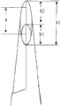
Fig. 5 is the decomposition vertical view of shears end of the present invention.
Fig. 6 is the decomposition side view of shears end of the present invention.
Fig. 7 is the decomposition side view that shears end of the present invention keeps tooth.
Fig. 8 is the decomposition vertical view that shears end of the present invention keeps tooth.
Fig. 9 representes the sliding process of suture material when the trial utilization is of the present invention.
Preferred implementation is described
As shown in Figure 3; The invention discloses a kind of surgical instruments 1 that comprises a pair of cross member 3a, 3b; A pair of cross member 3a, 3b have and are used to make cross member 3a, 3b pivotally to be fixed to fixture S each other; This fixture S is divided into first end 5 and second end 3 with surgical instruments 1, and wherein second end 3 comprises the locked plug-in unit 4 that is used to lock cross member 3a, 3b, and ends at finger reception ring 2; First end 5 comprises the clamping surface that is positioned at far-end.
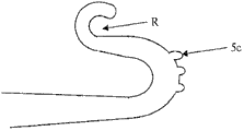
The clamping surface of first end 5 extends perpendicular to surgical instruments 1 main body, and is as shown in Figure 4, formed S shape far-end.This S shape far-end comprises two relative bending sections, a top that is positioned at another one, wherein on the first bending section 5a size greater than second bending section.As shown in Figure 5, the size of bending section can change according to purposes, and for example near body part, the length X 1 of first bending section can be extended.Yet at any time the length X 3 of second bending section is all less than the length X 1 of first bending section.Preferred disclosure of the Invention the range difference X2 between the first bending section length X 1 and the second bending section length X 3, said distance X 2 is greater than the second bending section length X 3.It is important understanding following content, and promptly the second bending section 5b is formed so that recess R to be provided, and the main purpose of recess R is that suture material 7 is remained on the appropriate location, to avoid suture material 7 at the direction superior displacement relative with being held works.Size impact surgical instruments 1 region covered of the said second bending section 5b, so bending section or recess R are more little, operate surgical instruments 1 is just easy more in operation process.The purpose of groove is not to contact with being held the surface, because can avoid suture material 7 to enter into said recess R like this.
Fig. 6 discloses the inner surface of clamping surface, and wherein said inner surface is longitudinally or laterally jagged.In addition, for a plurality of reasons, each bending section 5a, 5b are angled.The first bending section 5a is angled; More specifically the part that is connected with the second bending section 5b at the first bending section 5a is angled; So that the gradient between the bending section is provided, make suture material on the smooth surface S that tilts, move towards being held works from far-end or recess R.First jiao of θ 1 of the first bending section 5a preferably is equal to or greater than 60 degree.The main purpose of the second bending section 5b or recess R is to avoid suture material 7 in the direction slippage relative with being held works; The second bending section 5b or recess R have preferred second jiao of θ 2; More specifically for avoiding suture material along partly to have 2, the second jiaos of θ of preferred second jiao of θ, 2 to the first angle θ 1 less relatively with second bending section that is held the displacement of the relative direction of works.Content is very important below understanding; The part that promptly connects the first bending section 5a and the second bending section 5b is to extending more at a distance; Like Fig. 7 and shown in Figure 8; First bending section is and is held the contacted bending section of works that first bending section comprises having a plurality of protuberances that extend from first bending section 5a surface or the grip structure of tooth 5c.
Fig. 9 representes a plurality of steps of sewing process.Aforesaid surgical instruments has locking device, and the locking device purpose is when said cross member is clamped works 6, to lock the first cross member end.Be held works, blood vessel closely contacts far-end 5, shown in Fig. 9 a usually.Be necessary to point out that the first bending section 5a is and is held the part that works 6 fully contacts.The second bending section 5b does not contact with being held works 6, because this can make suture material complicate in the layout at the recess R place of the said second bending section 5b.After clamping works 6, suture material 7 is located in the second bending section 5b, make when the user when finger receives ring 2 pulling suture materials 7, recess R keeps said suture material to face the front portion of surgical instruments 1.In order to form a knot, around the rear portion intersection suture material 7 away from far-end 5 of surgical instruments 1 and orthopaedic surgical operations apparatus 1.Further, suture material 7 is pushed to and is held works 6, shown in Fig. 9 c.The inclination smooth surface S that connects the first bending section 5a assists suture material 7 to slide to the said surface 6 that is held.Fig. 9 d representes the final position of suture material 7.To be held the hemorrhage of works 6 in order controlling, to tie and fixed-node.Surgery clamp 1 of the present invention has been avoided in the near-end slippage of attempting to clamp suture material when being held works, and need not use several apparatuses to assist sewing process.
Although the present invention has been described to have preferred design; It should be understood that for a person skilled in the art; After considering this description and accompanying drawing; Many changes of the present invention, adjustment, variation and other purposes and application will become obviously, and can not violate novel teachings of the present invention and advantage in fact.Correspondingly, all these change, adjustment, variation and other purposes and application of not violating the spirit and scope of the present invention are considered to be that the present invention covers, as what in following claim and its legal equivalents, limited.In claim, device adds function (means-plus-function) clause, if having, its objective is the structure that comprises the said function of enforcement described herein, and not only structural equivalent, also has structure of equal value.
All patents, the patent application of being quoted in this paper and the appended statement (if any) and being published in here incorporated into way of reference, as here with its whole elaboration.All or all in fact disclosed parts in these patents can be used in the embodiment of the present invention, and their equivalent too.The detailed description of the patent that this paper incorporates into way of reference, patent application and announcement can be considered to can be merged in according to applicant's right to choose in the claim at pendend lite; As the further restriction in claim, on patentability, to differentiate the prior art of the claim of any correction and any application.
Claims (9)
1. surgery clamp apparatus comprises:
A pair of cross member, it has and is used for pivotally being fixed to fixture each other to said cross member, thereby has produced first end and second end,
Second end of wherein said cross member comprises that finger receives the locked plug-in unit that encircles and be used for said a pair of cross member is locked in settling position,
First end of wherein said cross member comprises the clamping surface that is positioned at far-end; And said far-end has the surface of at least the first bending section, second bending section and inclination; Wherein said first bending section and said second bending section are against each other; And the size of said first bending section is greater than the size of said second bending section, and is located in the top of said first bending section comprising said second bending section of groove.
2. surgery clamp apparatus as claimed in claim 1, wherein said first bending section and said second bending section form S shape part at said far-end.
3. surgery clamp apparatus as claimed in claim 1, wherein said first bending section and said second bending section comprise the smooth outer surface and the zigzag inner surface of assisting the suture material slippage.
4. surgery clamp apparatus as claimed in claim 1, the outer surface of the surface of wherein said inclination and said first bending section tilts, to assist the slippage of suture material.
5. surgery clamp apparatus as claimed in claim 1, wherein said first bending section comprise the tooth that extends from the surface of said first bending section.
6. surgery clamp apparatus as claimed in claim 1, wherein said first bending section becomes to be equal to or greater than the angle of 60 degree.
7. surgery clamp apparatus as claimed in claim 1, wherein said first bending section and said second bending section are angled, and the angle of said second bending section is less than the angle of said first bending section.
8. method that is used to sew up comprises:
The surgery clamp,
Suture material,
Wherein said surgery clamp comprises a pair of cross member, and said a pair of cross member has and is used for pivotally being fixed to fixture each other to said cross member, thereby has produced first end and second end,
Wherein said second end comprises that finger receives the locked plug-in unit that encircles and be used for said a pair of cross member is locked in settling position,
Wherein said first end comprises the clamping surface that is positioned at far-end; And said far-end has the surface of at least the first bending section, second bending section and inclination; Wherein said first bending section and said second bending section are against each other; Be located in the top of said first bending section comprising said second bending section of groove
Wherein sewing process comprises:
Make first end of said surgery clamp clamp works at said far-end;
Be placed on said groove to said suture material, receive the said suture material of ring pulling towards said finger simultaneously;
Move said suture material around said surgical instruments and away from said far-end;
The compactness that produces staggered suture material at the rear portion of said surgical instruments is intersected;
Promote said suture material towards being held works, the displacement of said suture material is assisted on the surface of wherein said first bending section;
Tie the said intersection of staggered suture material, to control said the hemorrhage of works place that be held; And
Discharge the said works that is held.
9. the method that is used to sew up as claimed in claim 8, wherein said first bending section closely contacts with the said works that is held, and can not block said groove.
Applications Claiming Priority (3)
| Application Number | Priority Date | Filing Date | Title |
|---|---|---|---|
| US12/427,444 | 2009-04-21 | ||
| US12/427,444 US8435255B2 (en) | 2009-04-21 | 2009-04-21 | Surgical clamp |
| PCT/US2010/031877 WO2010123979A1 (en) | 2009-04-21 | 2010-04-21 | Surgical clamp |
Publications (1)
| Publication Number | Publication Date |
|---|---|
| CN102427768A true CN102427768A (en) | 2012-04-25 |
Family
ID=42981574
Family Applications (1)
| Application Number | Title | Priority Date | Filing Date |
|---|---|---|---|
| CN2010800197005A Pending CN102427768A (en) | 2009-04-21 | 2010-04-21 | Surgical clamp |
Country Status (10)
| Country | Link |
|---|---|
| US (1) | US8435255B2 (en) |
| EP (1) | EP2421449A1 (en) |
| JP (1) | JP2012524621A (en) |
| KR (1) | KR20120067974A (en) |
| CN (1) | CN102427768A (en) |
| AU (1) | AU2010239270A1 (en) |
| BR (1) | BRPI1006694A2 (en) |
| CA (1) | CA2759576A1 (en) |
| MX (1) | MX2011011097A (en) |
| WO (1) | WO2010123979A1 (en) |
Cited By (1)
| Publication number | Priority date | Publication date | Assignee | Title |
|---|---|---|---|---|
| WO2016074330A1 (en) * | 2014-11-14 | 2016-05-19 | 江苏江科知识产权运营有限公司 | Minimally invasive surgical instrument and method therefor for knotting and trimming |
Families Citing this family (1)
| Publication number | Priority date | Publication date | Assignee | Title |
|---|---|---|---|---|
| JP6927654B2 (en) * | 2017-08-26 | 2021-09-01 | 英次 湊 | Hair growth method using hair growth equipment |
Citations (5)
| Publication number | Priority date | Publication date | Assignee | Title |
|---|---|---|---|---|
| US2842132A (en) * | 1956-10-15 | 1958-07-08 | Luis R Soltero | Surgical clamp |
| US4611592A (en) * | 1983-08-05 | 1986-09-16 | Talboy Glenn E | Clamp for holding surgical lines |
| US5133724A (en) * | 1991-04-04 | 1992-07-28 | Pilling Co. | Abdominal aortic clamp |
| JPH09294746A (en) * | 1996-05-07 | 1997-11-18 | Silver Medical:Kk | Instrument for operation |
| CN200973731Y (en) * | 2007-05-29 | 2007-11-14 | 许林 | Vascular blocking clamp without generating wound |
Family Cites Families (3)
| Publication number | Priority date | Publication date | Assignee | Title |
|---|---|---|---|---|
| US1664112A (en) * | 1926-10-18 | 1928-03-27 | Junemann August | Surgical forceps |
| US3364933A (en) * | 1965-03-29 | 1968-01-23 | Leopold Seymour | Slidable surgical clamp |
| US4827929A (en) * | 1983-08-29 | 1989-05-09 | Joseph Hodge | Angulated surgical instrument |
-
2009
- 2009-04-21 US US12/427,444 patent/US8435255B2/en not_active Expired - Fee Related
-
2010
- 2010-04-21 KR KR1020117027676A patent/KR20120067974A/en not_active Application Discontinuation
- 2010-04-21 CA CA2759576A patent/CA2759576A1/en not_active Abandoned
- 2010-04-21 EP EP10767691A patent/EP2421449A1/en not_active Withdrawn
- 2010-04-21 WO PCT/US2010/031877 patent/WO2010123979A1/en active Application Filing
- 2010-04-21 BR BRPI1006694A patent/BRPI1006694A2/en not_active IP Right Cessation
- 2010-04-21 AU AU2010239270A patent/AU2010239270A1/en not_active Abandoned
- 2010-04-21 JP JP2012507344A patent/JP2012524621A/en active Pending
- 2010-04-21 MX MX2011011097A patent/MX2011011097A/en not_active Application Discontinuation
- 2010-04-21 CN CN2010800197005A patent/CN102427768A/en active Pending
Patent Citations (5)
| Publication number | Priority date | Publication date | Assignee | Title |
|---|---|---|---|---|
| US2842132A (en) * | 1956-10-15 | 1958-07-08 | Luis R Soltero | Surgical clamp |
| US4611592A (en) * | 1983-08-05 | 1986-09-16 | Talboy Glenn E | Clamp for holding surgical lines |
| US5133724A (en) * | 1991-04-04 | 1992-07-28 | Pilling Co. | Abdominal aortic clamp |
| JPH09294746A (en) * | 1996-05-07 | 1997-11-18 | Silver Medical:Kk | Instrument for operation |
| CN200973731Y (en) * | 2007-05-29 | 2007-11-14 | 许林 | Vascular blocking clamp without generating wound |
Cited By (1)
| Publication number | Priority date | Publication date | Assignee | Title |
|---|---|---|---|---|
| WO2016074330A1 (en) * | 2014-11-14 | 2016-05-19 | 江苏江科知识产权运营有限公司 | Minimally invasive surgical instrument and method therefor for knotting and trimming |
Also Published As
| Publication number | Publication date |
|---|---|
| EP2421449A1 (en) | 2012-02-29 |
| KR20120067974A (en) | 2012-06-26 |
| BRPI1006694A2 (en) | 2016-04-12 |
| JP2012524621A (en) | 2012-10-18 |
| WO2010123979A1 (en) | 2010-10-28 |
| CA2759576A1 (en) | 2010-10-21 |
| MX2011011097A (en) | 2012-02-28 |
| US20100268269A1 (en) | 2010-10-21 |
| US8435255B2 (en) | 2013-05-07 |
| AU2010239270A1 (en) | 2011-12-08 |
Similar Documents
| Publication | Publication Date | Title |
|---|---|---|
| US5922008A (en) | Surgical forceps | |
| US5196023A (en) | Surgical needle holder and cutter for an endo-suture, endo-ligature or the like | |
| US4927425A (en) | Surgical rod pusher instrument | |
| US3006344A (en) | Surgical ligator and cutter | |
| US5171250A (en) | Surgical clips and surgical clip applicator and cutting and transection device | |
| US7850688B2 (en) | Electrosurgical instrument | |
| US4271838A (en) | Suture cutter | |
| CA2162837C (en) | Bone plate shaping device | |
| EP1254636A3 (en) | Surgical instrument for stapling and/or cutting with a wavy tissue interface | |
| US8272300B2 (en) | Hand tool articulating apparatus with offset handle | |
| WO2003039429A3 (en) | An ultrasonic clamp coagulator apparatus having an improved clamping end-effector | |
| GB2103934A (en) | Surgical suturing instrument | |
| MXPA03000006A (en) | Multipurpose clamp for medical use comprising two articulated jaws. | |
| US8535348B1 (en) | Surgical needle holder | |
| CN102427768A (en) | Surgical clamp | |
| US5618305A (en) | Forceps with v-shaped grasping tips | |
| US6015412A (en) | Cutting device | |
| EP2617368A1 (en) | Surgical needle holder | |
| US6063096A (en) | Needle holder | |
| DE60118562D1 (en) | MEDICAL PLIERS WITH TWO SWIVEL BAKING | |
| GB2210574A (en) | Improvements in forceps | |
| AU2016101793A4 (en) | Laparoscopic grasping and cutting instruments | |
| CN210843326U (en) | Laparoscope scissors | |
| WO1994028805B1 (en) | Safety skin hook and method | |
| JP5827737B1 (en) | Medical knife |
Legal Events
| Date | Code | Title | Description |
|---|---|---|---|
| C06 | Publication | ||
| PB01 | Publication | ||
| C10 | Entry into substantive examination | ||
| SE01 | Entry into force of request for substantive examination | ||
| C02 | Deemed withdrawal of patent application after publication (patent law 2001) | ||
| WD01 | Invention patent application deemed withdrawn after publication |
Application publication date: 20120425 |