CN102802541A - Devices, methods and kits for forming tracts in tissue - Google Patents
Devices, methods and kits for forming tracts in tissue Download PDFInfo
- Publication number
- CN102802541A CN102802541A CN2010800308811A CN201080030881A CN102802541A CN 102802541 A CN102802541 A CN 102802541A CN 2010800308811 A CN2010800308811 A CN 2010800308811A CN 201080030881 A CN201080030881 A CN 201080030881A CN 102802541 A CN102802541 A CN 102802541A
- Authority
- CN
- China
- Prior art keywords
- pipeline
- puncture member
- tissue
- organize
- housing
- Prior art date
- Legal status (The legal status is an assumption and is not a legal conclusion. Google has not performed a legal analysis and makes no representation as to the accuracy of the status listed.)
- Pending
Links
Images


Classifications
-
- A—HUMAN NECESSITIES
- A61—MEDICAL OR VETERINARY SCIENCE; HYGIENE
- A61B—DIAGNOSIS; SURGERY; IDENTIFICATION
- A61B17/00—Surgical instruments, devices or methods, e.g. tourniquets
- A61B17/34—Trocars; Puncturing needles
- A61B17/3478—Endoscopic needles, e.g. for infusion
-
- A—HUMAN NECESSITIES
- A61—MEDICAL OR VETERINARY SCIENCE; HYGIENE
- A61B—DIAGNOSIS; SURGERY; IDENTIFICATION
- A61B17/00—Surgical instruments, devices or methods, e.g. tourniquets
- A61B17/00234—Surgical instruments, devices or methods, e.g. tourniquets for minimally invasive surgery
- A61B2017/00292—Surgical instruments, devices or methods, e.g. tourniquets for minimally invasive surgery mounted on or guided by flexible, e.g. catheter-like, means
- A61B2017/003—Steerable
Abstract
Described here are devices, methods, and kits for forming one or more tracts in tissue. The tracts may be formed in any suitable or desirable tissue, and may seal relatively quickly without the need for a supplemental closure device. In some variations, the methods may comprise advancing a tissue-piercing member along a predetermined path of a tract- forming device to form one or more tracts in tissue (e.g., a vessel wall). The tract or tracts may, for example, provide access for one or more tools.
Description
Cross reference to related application
The application number that the application requires on May 15th, 2009 to submit to is 61/178,895 U.S. Provisional Application No., and this application integral body is quoted at this as a reference.
Technical field
This paper describes device, method and the kit utility that is used for forming at tissue one or more pipelines (tract).More specifically, this paper describes to be used for using and organizes device, method and the kit utility of puncture member at the one or more pipelines of tissue formation along the predetermined path movement of one or more parts (for example groove) through a device.
Background technology
Described before and manyly be used at tissue or pass the apparatus and method that tissue forms pipeline.For example, application number is 10/844,247 (publication number is US 2005/0267520 A1); 11/544,196 (publication number is US 2007/0027455 A1); 11/545,272 (publication number is US 2007/0032804 A1); 11/544,365 (publication number is US 2007/0032803 A1); 11/544,177 (publication number is US 2007/0027454 A1); 11/544,149 (publication number is US 2007/0032802 A1); 10/888,682 (publication number is US 2006/0009802 A1); 11/432,982 (publication number is US 2006/0271078A1); 11/544,317 (publication number is US 2007/0106246 A1); 11/788,509 (publication number is US 2007/0255313 A1); 11/873,957 (publication number is US 2009/0105744 A1); 12/507; 038 (publication number is US 2010/0016786 A1) and 12/507; The apparatus and method that are used for forming at tissue pipeline have been described, the quoting in full as a reference of all these applications in the U.S. Patent application of 043 (publication number is US 2010/0016810 A1) at this.Generally speaking, but pipeline self sealss of describing in these applications are perhaps capable of using minimum or need not add locking device or technology and they form after, seal.These pipelines are very useful when the passage that leads to tissue location (the for example chamber of organ) is provided, and make one or more instruments to advance and pass pipeline and can carry out one or more operations.Hope forms these methods of pipeline in tissue, additional apparatus and method can obtain using very widely.
Summary of the invention
This paper describes device, method and the kit utility that is used for forming at tissue one or more pipelines.Generally speaking, be used for can be used for making organizing puncture member to advance along predefined paths at the device that tissue forms pipeline.This tissue puncture member can its before the predefined paths reach, during or get into tissue at certain point afterwards.When organizing puncture member to advance to pass when organizing, it can form pipeline in tissue.Then, said pipeline can be used to make one or more instruments or other device to advance to target site.
In some modification; A kind of being used for can comprise housing and the puncture member of organizing that is connected to this housing at the device of the one or more pipelines of tissue formation, and wherein this tissue puncture member can be along being moved with respect to housing by the predetermined path of the one or more parts in the housing (for example groove).Organize the controlled relatively formation of the pipeline of puncture member in can allowing to organize along advancing of predefined paths (for example need operator less) to controlling of device.For example, the existence of predefined paths can allow to organize puncture member before piercing tissue, suitably to locate with respect to tissue.
Device described herein, method and kit utility can provide reproducible pipeline to form.For example, some modification of device described herein can be used for forming the roughly similar pipeline that passes two different blood vessel wall or pass two different positions in the same blood vessel wall.Thus, can before art, relatively easily predict the outcome.In addition, as the result of this predictability, the probability of makeing mistakes in the given operation is low.In some modification, organize the path of puncture member to select based on thickness of tissue, mechanical features and/or the biological characteristic that for example will form pipeline.
Some modification of device described herein can relatively easily be used.For example, a kind of device can be used in tissue to form pipeline and not need the operator firmly to apply moment of torsion or other is controlled.In some modification, device described herein can successfully be used by the training that received relatively less and/or to the limited operator of experience of the particular procedure that will carry out.For example, can use this device successfully to carry out arteriotomy to the limited operator of experience who carries out arteriotomy.Device described herein is difficult for being misapplied.For example, in some modification, a kind of device can or be operated the slidingtype actuator through pressing button simply and activate.The simplicity of this actuating can be limited in the probability of obscuring in the operating process of this device, and can allow to operate this device by the operator with different levels of skill.As an example, in some cases, a kind of device can be operated by very skilled operator, can be operated by the operator of experience relative deficiency again.In addition, the relatively easy device that uses possibly install safer than other, and this is because for example they cause that the probability that the operator slips up reduces.
In some modification, the operator can operate device described herein at a distance of a distance with the personnel's of experience operation health, simultaneously to organizing advancing and/or locate and carrying out the part and control of puncture member.For example, the operator can be through controlling the take up member that is connected to this device and/or waiting and activate this device and the remarkable body itself of actuation means not through compressing or activate one or more buttons, switch.This can prevent again that the operator from must make and microsclerly organize puncture member to advance to along complications or crooked route downwards microsclerly to organize the puncture member port and arrive target site.This advancing can cause and organize puncture member and organize the high frictional force between the puncture member port, overcomes high frictional force and make and organize puncture member to advance or the retracting tissue puncture member thereby need the operator to apply sizable power.When the operator applied sizable power, said device and/or surrounding tissue possibly be damaged, and/or organized puncture member possibly excessively advance (for example owing to discharge subsequently initial viscous effect) unpredictablely.Device described herein can need promote along their length and/or pulling organize puncture member to avoid these problems through elimination in fact.In addition, can organize puncture member and not need the heavy puncture member axle of organizing to handle identical zigzag path in the actuating of tortuous position.
In some modification, device described herein, method and/or kit utility can be used for forming self sealss and organize pipeline.Self sealss organize pipeline not need tampering devic or method to help its sealing---and promptly, it seals voluntarily.For example, self sealss organize pipeline not need connector, energy, sealant, clip, stitching thread etc. to help its sealing.On the contrary, self sealss organize pipeline when the relative tissue part along said pipeline contacts with each other and form sealing, can seal.This for example can occur in pipeline when shallow relatively with respect to the angle of tissue wall, and this angle can cause that pipeline has long relatively length and/or high surface area.Blood pressure can cause tissue part to contact with each other and natural coagulation factor etc. can cause their to form sealing.It should be understood, of course, that and to apply Manual pressure or to push the self sealss character that does not influence pipeline to promote its sealing the self sealss pipeline as back civilian said.
In some modification; A kind of device can comprise the housing that has at least one groove; Be connected on this housing at least one organize puncture member (that is, organize puncture member or a plurality of puncture member of organizing for, organize puncture member for for example two, three, four or five).Saidly organize puncture member to comprise to have the far-end that tissue pierces through top end, and can be along moving with respect to housing through the predetermined path of the configuration of groove.
In some modification, said device also can comprise being connected to be organized puncture member and is slidably disposed at least one protruding member (for example at least one pin) in the said groove.In some modification, said device can comprise organizes puncture member guiding device (for example will organize puncture member be connected to housing organize the puncture member guiding device).Said therein device also comprises in some such modification of at least one protruding member, protruding member with organize the puncture member both to be connected to organize the puncture member guiding device.In some modification, organize the puncture member guiding device to comprise and be slidably disposed at least one part in the said groove.For example, saidly organize the puncture member guiding device can comprise body and outstanding and be slidably disposed at least one protruding member (for example at least one pin) in the said groove from this body.In some modification, the said body of puncture member guiding device of organizing can limit the hole (for example path) of organizing puncture member to pass.
In some modification, said device can comprise at least one take up member, for example cable.Said therein device comprises in some modification of protruding member that said take up member can connect (for example merging) to protruding member.Alternatively or in addition, said protruding member can limit the hole of passing it.Said take up member can be passed this hole, and in some cases, said take up member can be connected to protruding member in this hole.In some modification, said device can comprise and is connected to housing or becomes whole rotating parts with housing, and said take up member can be connected to this rotating parts.Said rotating parts can for example comprise belt wheel, and said take up member can be wound onto around this belt wheel.In some modification, said device can comprise that being connected to housing perhaps becomes whole protruding member (for example pillar) with housing, and wherein said take up member is connected to (for example being wound on) protruding member (on every side).In some modification, said take up member can cause towards the translation of nearside organizes the translation of puncture member towards the distally.
In some modification, the said puncture member of organizing can be connected to housing at pivotal point.In some modification, the said at least a portion of puncture member of organizing can be arranged in the tubular element, and this tubular element is connected to housing at pivotal point.Said device can comprise at least one take up member, and this take up member not only had been connected to housing but also had been connected to organizes puncture member, and can control so that organize puncture member to pivot around pivotal point.Organize puncture member can comprise needle-like piece.The said puncture member of organizing can comprise at least a shape-memory material and/or at least a elastic material.
In some modification, said device can comprise tubular element.Said tubular element can rotate (articulatable) and/or can be connected to housing through at least one flexible member (for example at least one hinge) with respect to the housing articulated type.In some modification, the said part of puncture member of organizing can be arranged in the tubular element.In some modification, said tubular element can be connected to organizes puncture member.In some such modification, said tubular element can with port (the for example port on the housing) be connected to organize puncture member make this port with organize the puncture member fluid communication with each other.In some modification, housing can comprise at least two grooves therein, and tubular element can be positioned between two pins that are slidably disposed in the said groove at least.
Said housing can comprise at least one zigzag part.In some modification, said device can comprise the vacuum ports that is arranged in the zigzag part.Alternatively or in addition, said housing can comprise from zigzag partly outstanding at least one claw or barb member, and/or can in the zigzag part, have rough surface and/or coating.
Said device can comprise at least one pick off.For example, said device can comprise one or more temperature sensors, pressure transducer and/or blood flow pick off (for example doppler instrument).
In some modification; A kind of being used for can comprise that in the method that tissue forms pipeline pipeline being formed device is positioned near the tissue; This pipeline forms device and comprises housing and be connected to the puncture member of organizing of this housing, and makes and organize puncture member to advance along the predefined paths that is limited at least one groove in the housing (for example curved path).Said pipeline forms device and can comprise and be connected to the take up member of organizing puncture member and housing, and said method can comprise and controls take up member so that organize puncture member to advance along predefined paths.In some modification, can control take up member through regaining take up member towards nearside.In some modification, the said puncture member of organizing can at least partly be arranged in the tubular element that is connected to housing, and said method can comprise and controls tubular element so that organize puncture member to advance along predefined paths.In some modification, said method can comprise making organizes puncture member to advance in the tissue.
In some modification; A kind of being used for can comprise that in the method that blood vessel wall (for example arterial wall) forms pipeline pipeline being formed device is positioned near the blood vessel wall; And make and organize puncture member to advance in blood vessel wall, to form pipeline along the predefined paths that pipeline forms device, wherein the part of pipeline (for example fraction or the major part) longitudinal axis that is roughly parallel to blood vessel wall crosses blood vessel wall.
In some modification; A kind of being used for can comprise that in the method that blood vessel wall (for example arterial wall) forms pipeline pipeline being formed device is positioned near the blood vessel wall; And the predefined paths that makes at least one organize puncture member to form device along pipeline advances in blood vessel wall, forming pipeline, wherein said pipeline with respect to the longitudinal axis of blood vessel wall form be less than or equal to about 30 ° (for example be less than or equal to about 19 °, be less than or equal to about 15 °, be less than or equal to about 10 °, be less than or equal to about 5 °, from about 1 ° to about 19 °, from about 1 ° to about 15, from about 1 ° to about 10 °, from about 1 ° extremely about 5, from about 5 ° to about 15 °, from about 5 ° to about 10 °) angle.
Pipeline forms device can comprise housing, and when organizing puncture member in blood vessel wall, to form pipeline, this housing remains on roughly the same position.In some modification, said pipeline forms device and can comprise housing and not only be connected to the take up member of organizing puncture member but also being connected to this housing.In some such modification, said method can comprise controls take up member so that organize puncture member to advance along said predefined paths.Control take up member through regaining take up member towards nearside.
Organize puncture member to get into tissue in primary importance, and in second position exiting tissue, and the length between the primary importance and the second position can be greater than the thickness of tissue or tissue wall (for example blood vessel wall).In some modification, the length of pipeline can be greater than the thickness of tissue or tissue wall (for example, blood vessel wall).In some modification, said method can comprise to be made one or more instruments and/or locking device be advanced in the pipeline and/or passes pipeline.For example, in some modification, can make epitheca (for example conductor epitheca) advance in the pipeline and/or pass pipeline.This epitheca can for example be used to expand pipeline so that pass it carries out operation.After operation has been accomplished, retractable sheath and pipeline salable (for example self sealss).In some modification, said method can comprise exerts pressure to pipeline.
Some modification of method described herein can comprise from tissue or tissue wall (for example blood vessel wall) retracting tissue puncture member.Pipeline can organize puncture member to be retracted self sealss afterwards.As stated, self sealss organize pipeline not need tampering devic or method to help its sealing---and promptly, it seals voluntarily.For example, self sealss organize pipeline not need connector, energy, sealant, clip, stitching thread etc. to help its sealing.
Here the pipeline self sealss relatively apace that form.For example; Pipeline can be in 15 minutes or shorter time (for example in 12 minutes or shorter time, in 10 minutes or shorter time, in 9 minutes or shorter time, in 6 minutes or shorter time, in 5 minutes or shorter time, in 3 minutes or shorter time, in 1 minute or shorter time, or the like) sealing.Certainly, if hope that one or more additional locking devices can use with described apparatus and method in combination like this.
Said method can comprise at least one in sensing temperature, pressure and the blood flow.In some modification, a kind of method can comprise in addition tissue is applied vacuum and/or grasping tissue.In some modification, a kind of method can be included in tissue applied to make after vacuum and/or the grasping tissue organizes puncture member to be advanced in the tissue.Some modification of method described herein also can comprise clamping or separating tissues otherwise, and position tissue passes tissue to be used to organizing puncture member relatively easily to advance, at least a portion of tissue, to form pipeline.Being used for tissue is applied vacuum or swabbing action and clamp method is 12/507 at application number for example with other tissue positioned or partition method; 038 (publication number is US 2010/0016786 A1) and 12/507; Describe in the U.S. Patent application of 043 (publication number is US 2010/0016810 A1), preamble is quoting in full at this as a reference these two applications.
In some modification, the method that a kind of tissue (for example blood vessel wall) that is used in main body forms pipeline can be included in and form single pipeline in the tissue.This single pipeline can for example be self-packing.As stated, self sealss organize pipeline not need tampering devic or method to help its sealing---and promptly, it seals voluntarily.For example, self sealss organize pipeline not need connector, energy, sealant, clip, stitching thread etc. to help its sealing.This single pipeline can be for example through only making one to organize puncture member to advance to pass tissue and form.This can for example produce the minimum stress to tissue.In addition, tissue can be fully recovered relatively apace, produces short relatively operating time thus.In some modification, the passage in the zone (chamber that for example limits) that this single pipeline can be used for providing arrival to be limited in this tissue blood vessel wall.In some modification; The method that a kind of tissue (for example blood vessel wall) that is used in main body forms pipeline (for example self sealss pipeline) can comprise through making at least one organize puncture member to advance to pass at least a portion of tissue and in tissue, form pipeline that wherein the formation of pipeline only need make one or more at least a portion of organizing the puncture member reach through tissue.
The said puncture member of organizing can for example be a needle-like piece, for example hollow needle-like piece or solid needle-like piece.This needle-like piece can have any suitable top end that comprises any suitable shape.For example, this top end can be conical, conical, blunt, sharp partially or point, bevelled, slope-less etc.
The pipeline that utilizes device described herein, method and/or kit utility to form can form in any tissue suitable or that hope.For example, this tissue can be the organ of any body system (for example cardiovascular system, digestive system, respiratory system, Excretory system, reproductive system, nervous system etc.).In some modification, this tissue can be the organ of cardiovascular system, for example heart or tremulous pulse.In other modification, this tissue can be the organ of digestive system, for example stomach or intestinal.In some modification, this tissue can be the tissue of blood vessel wall (for example arterial wall).Said apparatus and method can be used for being fit in their any tissue of purposes.
Description of drawings
Figure 1A-1F illustrates the unfolded side cross-sectional, view of organizing puncture member of a modification that is used for forming at tissue the device of one or more pipelines; Fig. 1 G-1J is illustrated in the device of organizing Figure 1A-1F that puncture member advances in the process in different time points; And Fig. 1 K-1Q illustrates the device that utilizes Figure 1A-1J and in tissue, forms pipeline.
Fig. 1 R-1T illustrates the different modification of the pipeline in the tissue.
Fig. 1 U is the side cross-sectional, view of another modification that is used for forming at tissue the device of one or more pipelines.
Fig. 1 V is the example cross section of a modification of the self sealss pipeline of solidnever tube wall.
Fig. 2 A-2G illustrates and is used for utilizing the modification of the device of Figure 1A-1J in the method for the one or more pipelines of tissue formation.
Fig. 3 A-3C illustrates the different modification that are used for forming at tissue the device of one or more pipelines.
Fig. 4 A-4D is the partial section that is used for forming at tissue the device of one or more pipelines, and the expansion of organizing puncture member of said device is shown.
Fig. 5 A and 5B illustrate the partial section of other modification that is used for forming at tissue the apparatus and method of one or more pipelines.
Fig. 5 C is the partial section of a modification that is used for forming at tissue the device of one or more pipelines.
Fig. 6 A and 6B illustrate the modification that is used for forming at tissue the apparatus and method of one or more pipelines.
Fig. 7 A-7C illustrates the expansion of organizing puncture member of another modification that is used for forming at tissue the device of one or more pipelines.
Fig. 8 A and 8B illustrate another modification that is used for forming at tissue the device of one or more pipelines, with relevant method.
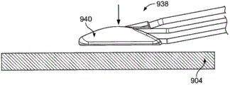
Fig. 9 A is the sketch map that is used in the far-end of the exemplary means that forms one or more pipelines in the tissue; And Fig. 9 B-9N illustrates the device that is used for utilizing Fig. 9 A and forms the illustrative methods of pipeline at tissue, and wherein Fig. 9 H and 9I specifically illustrate the distal expansile parts of the coupling of the guide wire that is used to supply method use described herein.
Figure 10 A is the general view how device described herein advances and pass the nature body cavities and be used for forming at tissue pipeline, and in this example, said tissue is a stomach.
Figure 10 B and 10C provide the exemplary variation of FLUID TRANSPORTATION and collection structure.
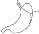
Figure 11 A-11I illustrates and is used in stomach tissue or passes the illustrative methods that stomach tissue forms pipeline.
Figure 12 A-12D illustrates according to the illustrative methods of method described herein near the heart peripheral space.
Figure 13 A-13K illustrates the illustrative methods that is used for forming in heart tissue pipeline.
The specific embodiment
This paper describes device, method and the kit utility that is used for forming at tissue pipeline.For example, device described herein, method and kit utility can be used for passing for example blood vessel wall formation pipeline of tissue wall.Generally speaking, said pipeline can relatively easily and with controlled way form.The formation of particular conduit also can be reproducible.Therefore, device described herein, method and/or kit utility can provide the operation of the predictability with raising.Device described herein, method and kit utility can allow relatively accurately, form easily and effectively pipeline.In some modification, device described herein, method and/or kit utility are can be by experience limited or do not have the operator of experience (for example being used for training) to use.Because said device, method and/or kit utility use can be relatively easily and simply, so the operator of experience relative deficiency can utilize said device, method and/or kit utility successfully to carry out operation.
In some cases, the pipeline that utilizes device described herein, method and/or kit utility to form can or not have the additional seal action and self sealss with minimum additional seal action.As stated, self sealss organize pipeline not need tampering devic or method to help its sealing---and promptly, it seals voluntarily.For example, self sealss organize pipeline not need connector, energy, sealant, clip, stitching thread etc. to help its sealing.But should be understood that through using one or more additional closing means or technology (for example locking device, energy delivery, exert pressure etc.), can replenish device described herein, method and kit utility.For example, in some modification, can apply compression to realize hemostasis.
In some modification, device described herein and/or method are used in and form single pipeline (for example wherein this single pipeline is self-packing) in the tissue.
Device described herein, method and kit utility can supply to hope that any tissue that forms one or more pipelines therein uses.For example, this tissue can be an organ, the organ of for example any body system (for example cardiovascular system, respiratory system, Excretory system, digestive system, reproductive system, nervous system etc.).In some modification, this tissue can be the organ of digestive system, for example stomach or intestinal.In other modification, said device, method and kit utility can supply the for example vascular system (for example tremulous pulse) or the heart use organized of cardiovascular system.As an example, the muscular wall and/or the barrier film that can pass heart form one or more pipelines, to arrive left ventricle, aorta, aortic valve, Bicuspid valve, aortic arch etc.For example, organize puncture member to can be used for passing the muscular wall of heart and getting into the barrier film of heart and form pipeline from the side face of heart.In some modification, organize puncture member to can be used for forming to get into heart through the apex of the heart (transapical) pipeline.In some modification, said tissue can be a tremulous pulse, and said method can be used with the execution arterypuncture in combination.In some modification, can pass the tract of nature and arrive said tissue (for example in order to carry out the Minimally Invasive Surgery use endoscope to carry out as approach /) through natural tract endoscopic surgery " NOTES " through human body natural's tract.Said tissue can be the tissue of reproductive system, Excretory system, consumption systems etc. for example.It should be understood, of course, that and also can expect in tissue, no matter passing similarly or different tissues forms the method for a plurality of pipelines.
Although device described herein, method and kit utility are described as with to organize pipeline to form relevant, some modification of said device, method and/or kit utility can be alternatively or are used for one or more other purposes in addition.For example, they can be used for one or more the diagnosis with and/or therapeutic preparation (for example medicament) be transported to tissue.
Figure 1A-1F illustrates exemplary variation and the operation thereof that is used for forming at tissue the device (100) of one or more pipelines.Shown in Figure 1A, device (100) comprises housing (102), and this housing has two grooves (104) and (106) therein.Housing (102) has zigzag part (119), and this zigzag part can for example be used to help position tissue to pierce through to be used for tissue, and is as described in greater detail below.Device (100) also comprises organizes puncture member guiding device (108), two protruding members (as shown in the figure, pin (112) and (114)) that this tissue puncture member guiding device comprises body (110) and gives prominence to from this body.Pin (112) and (114) is slidably disposed in groove (104) and (106).Organize puncture member guiding device (108) to be connected to have that tissue pierces through top end (117) and tube chamber (121) organizes puncture member (116).As shown in the figure, the hole (path (123) here) in the body of organizing puncture member (116) to pass to organize puncture member guiding device (108) (110).But, in some cases, organize puncture member to be connected in a different manner and organize the puncture member guiding device.For example, organize puncture member can be attached (for example welding) to the outer surface of organizing the puncture member guiding device.In some modification, organize puncture member to become whole with organizing the puncture member guiding device.
In this modification, organize puncture member guiding device (108) also to be connected to take up member (118).Take up member (118) can for example extend through the hole (not shown) in the body (110) of organizing puncture member guiding device (108).Usually, take up member (118) can be connected to body (110).For example, said take up member can be welded, merged, adhesion, moulding or molded or attached or in said hole, be connected to said body with any other suitable mode.Because this connection can be by organizing the puncture member guiding device to cause corresponding moving to controlling of take up member.Though a hole has been described, in some cases, extensible a plurality of (that is, at least two) hole passed in the body of organizing the puncture member guiding device of take up member.In some modification, take up member (118) replacedly or in addition is connected to one in pin (112) and (114) or both.As an example, said take up member can be wound onto around at least one in the said pin.In some modification, said take up member can be fused at least one in the said pin, and/or can pass the one or more holes at least one in the said pin.
In some modification, a kind of device can comprise a plurality of take up member, for example two, three, four or five take up member.For example, Fig. 1 U shows the device (180) that is used for forming at tissue one or more pipelines.This device comprises organizes puncture member guiding device (182), and this tissue puncture member guiding device has body (184), from this body outstanding two pins (186) and (188) and take up member (190) and (192), and each is sold and all is connected with a take up member.One or more holes (not shown) in the take up member one, two or the body (184) that do not have take up member to pass to organize puncture member guiding device (182).Also can use other layout of take up member.
Though show pin (112,114,186 and 188), can use the combination of any suitable protruding member or different protruding member (for example pillar etc.) in any device described herein.In addition, device can comprise the combination of the protruding member or the protruding member of any suitable quantity, and in some cases, and protruding member can be fixed on the device (for example making this protruding member in the guide rail of this device or groove, to slide).In comprising the device of a plurality of protruding members, protruding member can have identical form, size and/or shape, at least one difference in perhaps can be in these areas.In some modification, protruding member can be by independent actuating.In some modification, protruding member can be spring loaded.This can for example allow protruding member under spring tension, not need take up member along groove.Replacedly or in addition additionally, make spring-loading protruding member can help to adapt to the misalignment in the groove and/or can prevent the clamping stagnation in actuation process.
Shown in Figure 1A, device (100) comprises that also form is the rotating parts of the belt wheel (120) that is connected to housing (102).Take up member (118) is wound onto belt wheel (120) and be conducted through tubular element (122) on every side.Therefore, take up member (118) gets into housing in primary importance (124), is connected to and organizes puncture member guiding device (108), is wound on belt wheel (120) on every side, passes tubular element (122), and leaves housing (102) in the second position (126).Though take up member (118) is conducted through tubular element (122), some modification of device can not comprise such guiding tubular element, perhaps can comprise a plurality of such guiding tubular elements (for example being positioned in the different sections of device).In some modification, a kind of device can comprise one or more other assemblies that can be used for helping to guide take up member.In this modification, said device can also comprise also can not comprise one or more guiding tubular elements.
Because take up member (118) is wound on belt wheel (120) on every side, so belt wheel (120) can help to change the tensile direction in the take up member (118).Though device (100) comprises belt wheel (120), some modification of device can be alternatively or are additionally comprised the assembly of one or more other types that can be used for changing the tension direction in the take up member.As an example, a kind of device can comprise the take up member (for example being embedded in the plastics, in order to reduce the friction between projection or pillar and the take up member) that is wound on around projection (nub) or the pillar.As another example, in some modification, a kind of device can comprise the lever that can be used for changing the tensile direction in the take up member.Also can use other suitable assembly.
Take up member (118) can be to be applied in tensile any suitable member, and/or can be used for transmitting tensile any suitable member.The non-limiting example of suitable take up member comprises monofilament or multifibres (for example braiding) stitching thread or cotton rope (string), metal cords and comprises flat rubber belting, band or the belt of one or more metals, plastics and/or fiber-reinforced polymer.
Existing referring to Figure 1B; When the part of leaving housing (102) in the second position (126) when take up member (118) is pulled (along the direction of arrow (A1)) towards nearside, organize puncture member guiding device (108) along advancing towards the distally through groove (104) and (106) predetermined path.Organize puncture member guiding device (108) owing to organize puncture member (116) to be connected to, so organize puncture member (116) in company with organizing puncture member guiding device (108) to advance.As a result, organize puncture member (116) roughly to advance along the direction of arrow (A2).Yet, organize the progress path of puncture member can be according to the change of configuration of groove (104) and (106).For example, when one or two bending in the groove, organize puncture member guiding device (108) can when it crosses bend, change its direction of advance.
Certainly, though Figure 1B illustrates the groove with particular configuration and shape, can use any other suitable configuration and shape.In addition, a kind of device can have the groove of any suitable quantity.For example, a kind of device can have only groove, perhaps can have more than two grooves.Said groove can have any suitable size.A kind of therein device comprises in the modification of two grooves that at least two in the said groove can have identical size and/or shape at least, and perhaps all grooves all can be of different sizes and/or shape.Groove can be crooked, angled, straight, or the like.In some modification, groove can comprise visibly different guide rail or slit, perhaps can have the hemispherical cross sectional shape.The size of groove, shape and configuration can be for example selected based on the hope path of organizing puncture member to advance to pass tissue.
In addition, though organize puncture member guiding device (108) in groove, to advance, can use any other suitable mechanism by means of the slippage of pin.As an example, replace having groove, organize the puncture member guiding device can comprise housing, and can comprise and being suitable for along the progressive slidably parts of said track with one or more tracks.As another example, replace having pin (or except that having pin), organize the puncture member guiding device to comprise to be configured to groove or the roller or the bearing of guide rail rolling in the housing of device.
Existing referring to Fig. 1 C, along with the operator continues to organize puncture member guiding device (108) owing to the bending of groove (104) and (106) changes its orientation along the said part of the direction pulling take up member (118) of arrow (A1).This makes organizes puncture member (116) to be changed direction, and it advances towards the distally along the direction of arrow (A3) now like this.Similarly, along with organizing puncture member (116) to move on, it is changed direction once more, makes it advance along the direction of arrow (A4), shown in Fig. 1 D.Referring to Fig. 1 E, then, organize puncture member (116) to be changed direction again at present, make it advance along the direction of arrow (A5).Certainly, Figure 1B-1E only illustrates various break-ins and a progressive example of organizing puncture member, and can use suitable any combination.But waiting, the shape of advancing with other physiological feature (clotting time of for example estimating) of the concrete combination based target anatomical tissue of break-in, main body, will be directed passing the instrument of formed pipeline of organizing puncture member selects.
Shown in Fig. 1 F, in some modification, it also can be returnable organizing puncture member (116), makes it can be recovered to towards nearside in the housing (102) of device (100).More specifically, through pulling (along the direction of arrow (A6)) on the part of leaving housing (102) in take up member (118) in primary importance (124), organize puncture member (116) to be withdrawn in the housing (102) along the direction of arrow (A7).
Existing referring to Fig. 1 G-1I, along with organizing puncture member (116) to advance, organize the position change of puncture member with respect to device from device (100).This takes place owing to organizing puncture member guiding device (108) to change its orientation along groove (104) and (106) during reach at it.Shown in figure, organize puncture member (116) organizing puncture member (116) to take when advancing with respect to device (100) more and more steeper orientation.But, should be understood that other modification that is used for forming at tissue the device of pipeline can comprise in use along the progressive puncture member of organizing of different tracks.
Fig. 1 G is illustrated near the device (100) the expansion section start of organizing puncture member.Shown in figure, organize puncture member (116) to have longitudinal axis (LA1), and the bottom surface (130) of housing (102) have longitudinal axis (LA2).Longitudinal axis (LA1) and (LA2) between have angle α
1In some modification, the angle α shown in Fig. 1 G
1Can be at least about 0 ° and/or about at the most 30 °.For example, the angle α shown in Fig. 1 G
1Can be from about 0.5 ° to about 30 ° (for example from about 0.5 ° to about 20 °, from about 0.5 ° to about 10 °, from about 0.5 ° to about 5 °) or from about 0 ° to about 10 ° (for example from about 0 ° to about 5 °).
Existing referring to Fig. 1 H, along with organizing puncture member (116) to move on angle α
1Increase (for example being increased to about 1 °) to about 45 ° scope, for example about 2 ° to about 30 °.Similarly, Fig. 1 I and 1J show angle α
1Size organizing the further increase of puncture member (116) when moving on.Shown in Fig. 1 I, for example, angle α
1Can be from about 10 ° to about 60 ° (for example from about 10 ° to about 30 °).Alternatively or in addition additionally, shown in Fig. 1 J, angle α
1Can be from about 12 ° to about 90 ° (for example from about 12 ° extremely about 60 ° or from about 20 ° to about 90 °).
The angle of spread that in organizing pipeline formation procedure, forms can for example be selected based on the characteristic of tissue.As an example, the tissue (for example intestinal tissue) that a kind of therein device is used in relative thin forms in some modification of pipeline, and the puncture member angle of spread of organizing of said device can be relatively little.In some cases, the final puncture member angle of spread (angle that for example is used to pass tissue and gets into the chamber) of organizing can be big relatively.For example, can be propped (tent) or can be organized under the situation that puncture member pushes open, possibly hope to adopt the big relatively angle of spread, so that piercing tissue successfully by progressive at tissue.
Should be understood that the different angles of spread shown in Fig. 1 G-1J are exemplary, and other modification other configuration that can have the angle of spread of device.For example, a kind of device can have the less different angles of spread, perhaps can have the different angles of spread of larger amt.In addition, though Fig. 1 G-1I illustrate longitudinal axis (LA1) and (LA2) between angle in expansion process, increase, in some cases, such angle can reduce at specific part in expansion process.In some modification, but manipulation of tissue puncture member guiding device is with the regulation that realizes the organizing puncture member angle of advancing.In some modification, organize the hope of the puncture member angle of advancing to become steeper along with the tissue wall thickening.
Fig. 1 K-1Q illustrates the device (100) that is used for forming in tissue wall (200) pipeline.At first, device (100) is sent to target site, is tissue wall (200) here.For example NOTES operation capable of using will be installed (100) and will be sent to target site.As an example, if tissue wall (200) is a coat of the stomach, can will installs (100) via esophagus so and be sent to tissue wall (200).In esophagus was used, said device can have and is configured to be engaged in the intraesophageal size with for example about 13 millimeters diameter this.Other NOTES operation near target site can be through stomach, transvaginal or per rectum.In addition, some modification of said device and/or method can be used for not only comprising the NOTES technology but also comprise in the mixing NOTES operation of laparoscopic technique, or other mixes in the operation.
The housing (102) of device (100) can comprise any suitable material or the combination of material, and can comprise one or more biocompatible materials usually.In some modification; Housing (102) or its part (for example its outer peripheral edges and/or tissue contact surface) can be processed by one or more softish relatively materials (for example softish relatively plastics or polymer), and install the inner assembly of (100) and/or can more there be rigidity in the more intermediary zone of housing (102).This can for example allow in operation process, relatively easily will install (100) and be manipulated to target site, still keeps structural intergrity and fully firm degree simultaneously.
The example that can be suitable for the material of housing (102) comprises polymer, for example polyacetals (for example
 acetal resin), polystyrene, polyether-ether-ketone (PEEK), PEKK (PEKK), polyethylene, acrylonitrile butadient styrene (ABS), PETG (PET), Merlon, politef (for example
 polymer), polyimides, nylon, silicones,
 TPV and polrvinyl chloride (PVC).The polymer of some types or polymer group can obtain with different hardness, and can use in this case for desirable characteristic and stark one or more right polymer.The example of the material of relative stiffness comprises PEEK, PEKK, ABS or silicones, and the example of softish relatively material comprises silicones,
 TPV and
 polymer.Certainly, these are exemplary materials, and if suitable, also can use other relative stiffness or softish relatively material.In addition, can use not particularly soft or inflexible material.In addition, in some modification, can use combination of different materials (for example mixture).For example, can use the blend of polymer, perhaps can use composite a kind of and multiple polymers and packing material (for example fibre glass and/or granule, carbon fiber etc.).
In some modification, device (100) can be sent to target site through peritoneoscope, and can be conditioned (scale) to be engaged in the trocar that is used for laparoscopic surgery.In some modification, device (100) can advance to target site in epitheca.Device (100) can have can assist it to advance to pass the level and smooth and/or circular contour (for example cup-shaped or clamshell shape) of such epitheca.In some modification, device (100) can be sent to target site via one or more operative incisions.For example, device (100) can be via directly being sent to vascular by the otch in the skin of incision to vascular.In some modification, device (100) can be bonded in the bigger general arrangement, and this general arrangement can be sent to target site then, illustrates in greater detail like hereinafter.Though this paper has explained device (100), should be understood that when suitable the characteristic of device (100) and application are applicable to other device described herein, and vice versa.In addition, when suitable, the characteristic of any method described herein is applicable to other method described herein.
Shown in Fig. 1 K, first device (100) is aimed at the surface (202) of tissue wall (200).For example, if tissue wall (200) is the heart tissue wall, surface (202) can be the outer surface of heart tissue wall so.Device (100) can be made housing (102) flush with surperficial (202) by aligning, and is as shown in the figure, perhaps can be made the only a part of contact surface of housing (102) (202) by aligning, or makes housing (102) contact surface (202) not at all.Referring to Fig. 1 K, as shown in the figure again, the part of tissue wall (200) is arrived in the zigzag part (119) of housing (102) by drawing.This can for example realize through contact surface (202) on the surface that is resisted against tissue and along the direction mobile device (100) of arrow (A8).Alternatively or in addition, in some modification, a kind of device can comprise the zigzag part with suction or vacuum component, or indentation but have the part of suction or vacuum component not, and it can be used for organizing drawing to arrive the position of hope.In addition, though described the zigzag part, in some modification, can use part to come inside drawing tissue or otherwise locate or separating tissues with isomorphism type not.For example, a kind of device can comprise the more rounded slot part that plays with zigzag part 119 similar effects.
Shown in Fig. 1 L; After device (100) has been placed in the position of hope; Can leave the part of housing (102) in the second position (126) along the direction pulling take up member (118) of arrow (A1), so that organize puncture member (116) to begin to advance in the tissue wall (200).Then, can continue to make and organize puncture member to advance to pass tissue wall (Fig. 1 M), passed tissue wall (Fig. 1 N and 1O) up to it.For example, be under the situation of blood vessel wall in tissue wall (200), organize puncture member to advance and pass blood vessel wall up to organizing puncture member to get into the chamber that limits blood vessel wall.Like this, organize puncture member (116) in tissue wall (200), to form pipeline (204) (Fig. 1 Q).The characteristic of pipeline (204) can for example be selected based on one or more characteristics of tissue wall (200).
In some cases, device capable of using (100) and/or utilize one or more in other device described herein and/or the method and relatively easily form for example pipeline (204) of pipeline.For example, through in the pulling simply on take up member (116) afterwards of positioner (100) suitably, but operator's formative tissue pipeline.Certainly, though described take up member, replacedly or in addition adopt the control device of other form.As an example, in some modification, can use one or more slidingtype actuators, switch, button or other like to come manipulation of tissue to form device.These actuated components can be positioned on nearside, perhaps can otherwise be positioned to be configured to be easy to the position by operator's use.
Device (100) is used in the part that tissue has relative thickness or organizes in the part of the thickness with variation and forms pipeline.In addition, in some modification, a kind of device can have the puncture member of organizing that can cross two or more different tissues.For example, a kind of device can have the puncture member of organizing that has two different tracks, serous coat that can be used for crossing stomach wherein, and wherein another can be used for crossing the mucosa of stomach.
Though the method that more than illustrates and describe is to pass a kind of mode that tissue forms pipeline, can use other appropriate method certainly.For example, certain methods can adopt that device activates organizes puncture member to advance to organize the progressive combination of puncture member with manual.In addition, in some modification, the first of pipeline can organize puncture member to form by first, and the second portion of pipeline can be formed by the second different puncture member of organizing.Can use any right quantity organize puncture member to form to install pipes with the combination of organizing puncture member.
In some modification, organizing puncture member formed pipeline in tissue wall after, organize puncture member can remain in this tissue wall, and one or more guide wire and/or other instrument or device advance to pass or surpass and organize puncture member.Like this, this tissue puncture member can be guide wire, instrument and/or device passage and the path that passes or get into tissue wall is provided.In some modification, guide wire can pass organizes puncture member, and organizes puncture member to be retracted.Then, this guide wire can be used for making one or more instruments or device to advance passing tissue wall.The instrument that passes pipeline that advances can be used for for example diagnosing operation and/or treatment operation.
Fig. 1 P is illustrated in and in tissue wall (200), forms pipeline (204) and just organize puncture member (116) from what tissue wall (200) was retracted afterwards.Shown in figure, can leave the part of housing (102) in primary importance (124) towards nearside (along the direction of arrow (A6)) pulling take up member (118), with from tissue wall retracting tissue puncture member.For example, in the time no longer need organizing puncture member, perhaps when organizing puncture member to be deployed into non-target site by accident, the operator can select the retracting tissue puncture member.
Existing referring to Fig. 1 Q, and as stated, pipeline (204) is by organizing puncture member (116) to form.Shown in Fig. 1 Q, pipeline (204) has the shape of gentle dip, has length (L) and height (H).But, should be understood that pipeline (204) just can pass an example of the pipeline configuration of tissue formation, and replacedly or in addition add and use other suitable configuration.As an example, the angle of pipeline can be bigger, perhaps can be diagonal, perhaps can have one or more diagonal angles part.In some modification, pipeline can comprise one or more tilting zones, one or more flat region and/or with one or more zones of the longitudinal axis and/or the surperficial almost parallel of tissue wall.In blood vessel wall (for example arterial wall), form therein in some modification of pipeline, said pipeline can comprise with the longitudinal axis almost parallel in the chamber of this vascular and/or with one or more zones of the surperficial almost parallel of blood vessel wall.In some modification, organize puncture member can be configured to advance in the tissue, thereby and can form the wavy pipeline that passes tissue along the fluctuating path.This wavy pipeline can for example have than by the big surface area of other pipeline of organizing puncture member to form along relatively more straight path.This bigger surface area can allow the relatively easy self sealss of this pipeline (for example owing to hereinafter described one or more reasons).Ducted fluctuating quantity can be slight or tangible in some cases.If for current application-specific, be fit to, then also can form other configuration (for example zigzag pipeline, swing pipe etc.) of pipeline.
The length of pipeline (the for example length (L) of pipeline (204)) can be any suitably or the length of hoping.In some modification, this length can be chosen to help pipeline and seal relatively fast.For example, when apparatus and method described herein supply vascular to use, the longer pipe road maybe be hoped, the helpful biological factor (for example growth factor, organizational factor etc.) that to assist closed conduit will be presented because believe the longer pipe road.Other is organized also possibly be this situation.In addition, the longer pipe road will have the bigger area that is used for action mechanical pressure, and this can make pipeline seal more quickly.In some modification, length (L) can be greater than the thickness of tissue wall (200) (for example forming the position of pipeline (204), perhaps with respect to the average thickness of tissue wall (200)) in tissue wall (200)).Here, certainly, the height (H) of pipeline (204) equals the thickness of tissue wall (200).Yet in some cases, pipeline can have the height less than tissue wall thickness.For example, can form pipeline with in the inner section that one or more medicine for treatment agent is deposited in part tissue.In blood vessel wall, form therein in some modification of pipeline, the part of pipeline (for example fraction or major part) can with the surperficial almost parallel of the longitudinal axis of blood vessel wall and/or blood vessel wall cross blood vessel wall.
Pipeline can have any suitable orientation or configuration with respect to the tissue that they are formed on wherein.As an example, Fig. 1 R illustrates the illustrative conduit (206) in the tissue wall (208).Shown in figure, pipeline (206) forms the diagonal path of passing tissue wall (208).Tissue wall (208) has outer surface (210) and inner surface (212).For example, in some modification, tissue wall (208) can be a blood vessel wall, and inner surface (212) can be over against the chamber of this blood vessel wall.Shown in Fig. 1 R, there is angle (α between pipeline (206) and the inner surface (212)
2).In some modification, angle (α
2) can be less than or equal to about 30 ° (for example are less than or equal to about 19 °, are less than or equal to about 15 °, are less than or equal to about 10 °, are less than or equal to about 5 °).In some modification, angle (α
2) can be from about 1 ° to about 30 ° (for example from about 1 ° to about 19 °, from about 1 ° to about 15 °, from about 1 ° to about 10 °, from about 1 ° to about 5 °, from about 5 ° to about 15 ° or from about 5 ° to about 10 °).In some modification, angle (α
2) can select based on tissue or the operation that is about to carry out.
Fig. 1 S illustrates and passes have the chamber another pipeline (214) of wall (216) of vascular (218) of (220).Shown in figure, chamber (220) have longitudinal axis (LA3), and pipeline (214) forms angle (α with longitudinal axis (LA3)
3).In some modification, angle (α
3) can be less than or equal to about 30 ° (for example are less than or equal to about 19 °, are less than or equal to about 15 °, are less than or equal to about 10 °, are less than or equal to about 5 °).In some modification, angle (α
2) can be from about 1 ° to about 30 ° (for example from about 1 ° to about 19 °, from about 1 ° to about 15 °, from about 1 ° to about 10 °, from about 1 ° to about 5 °, from about 5 ° to about 15 ° or from about 5 ° to about 10 °).
In some modification; The pipeline that passes tissue can have a plurality of (promptly; At least two) different zones, these zones with respect to benchmark for example surface, this tissue of this tissue longitudinal axis or under the situation of vascular the longitudinal axis in the chamber of this vascular become different angles.As an example, Fig. 1 T illustrates the pipeline (222) of the tissue wall (224) of passing have outer surface (226) and inner surface (228).Pipeline (222) comprise first area (230), with the angled second area in first area (232) and with angled the 3rd zone of second area (234).In Fig. 1 T, the dotted line (228 ') parallel and (228 ") are used for helping to illustrate the position of the zones of different of pipeline (222) with respect to inner surface (228) with inner surface (228).Shown in figure, first area (230) (228 ") (and therefore with respect to inner surface (228)) form angle (α with respect to dotted line
4), second area (232) forms different angle (α with respect to dotted line (228 ') (and therefore with respect to inner surface (228))
5), and the 3rd zone (234) form another different angle (α with respect to inner surface (228)
6).In some modification, angle (α
4) can be from about 0.5 ° to about 45 ° (for example from about 1 ° to about 30 °), angle (α
5) can be from about 1 ° to about 90 ° (for example from about 5 ° to about 60 °), and/or angle (α
6) can be from about 0.5 ° to about 45 ° (for example from about 1 ° to about 45 °).Certainly, though each in these angles is all different with other angle, in some modification, at least two zoness of different of passing the pipeline of tissue can form identical angle with respect to the surface of this tissue and/or the longitudinal axis of this tissue.In addition, and as stated, pipeline needn't have the configuration shown in this paper, and the configuration shown in this paper is exemplary.For example, pipeline can have than the regional more or less zone shown in this paper, and the combination that can have bending area, angled zone and/or wobble area perhaps can have any other suitable configuration.
Pressure for example blood pressure can act on the pipeline that uses the one or more formation in device described herein and/or the method, thereby and can make pipeline seal relatively apace and need not add locking device.For example; This pipeline can sealing in 15 minutes or shorter time (for example 12 minutes or shorter time, 10 minutes or shorter time, 9 minutes or shorter time, 6 minutes or shorter time, 5 minutes or shorter time, 3 minutes or shorter time, 1 minute or shorter time etc.), thereby shortens the persistent period of any external compression that possibly need.Certainly, if hope, can use one or more additional locking devices (for example connector, clip, sicker, stitching thread etc.), and/or can use additional enclosure method (for example apply mechanical pressure, apply swabbing action, apply one or more sealants etc.).These additional locking devices and/or method can help to promote seal process.
As stated, in some modification, can form self sealss and organize pipeline.Self sealss organize pipeline not need tampering devic or method to help its sealing---and promptly, it seals voluntarily.For example, self sealss organize pipeline not need connector, energy, sealant, clip, stitching thread etc. to help its sealing.In some cases, the angle between the longitudinal axis of said surface of organizing puncture member and said tissue or tissue wall (for example blood vessel wall) may be selected to and forms the self sealss pipeline.For example; This angle can be shallow relatively, for example be less than or equal to about 30 ° (for example be less than or equal to about 19 °, be less than or equal to about 15 °, be less than or equal to about 10 °, be less than or equal to about 5 °, from about 1 ° to about 30 °, from about 1 ° to about 19 °, from about 1 ° to about 15 °, from about 1 ° to about 10 °, from about 1 ° to about 5 °, from about 5 ° to about 15 ° or from about 5 ° to about 10 °)
Fig. 1 V illustrates the exemplary self sealss pipeline (280) of the part (282) of the wall (283) that passes vascular (284), and wherein this vascular has chamber (286).Shown in figure, pipeline (280) roughly is diagonal, and has length (L2).The length of this pipeline can be any length suitable or that hope, seals relatively fast to help this pipeline.For example, when apparatus and method described herein supply vascular system to use, possibly hope the longer pipe road.This is because believe, like above Short Description, the longer pipe road can manifest the helpful biological factor that can assist closed conduit (for example, growth factor etc.).Other is organized also possibly be this situation.In addition, the longer pipe road can have the big relatively area that is used for action mechanical pressure, and this can make pipeline seal more quickly.In some modification, length (L2) can be greater than the thickness of the part (282) of wall (283) position of the part (282) that forms pipeline (280) (for example).
Arrow shown in Fig. 1 V illustrates the pressure that acts on the pipeline and pipeline is sealed relatively apace and need not add locking device.Sealing when this pipeline can contact with each other and form sealing in the relative tissue part (for example relative tissue part (290) and (292)) along this pipeline.In some modification; This pipeline can seal in 15 minutes or shorter time, 12 minutes or shorter time, 10 minutes or shorter time, 9 minutes or shorter time, 6 minutes or shorter time, 3 minutes or shorter time, 1 minute or shorter time etc., thereby shortens the persistent period of any external compression (if existence) that possibly need.Certainly, if hope, can use one or more additional locking devices (for example, connector, clip, sicker, stitching thread etc.).
Method described herein can comprise the others except that above-mentioned pipeline forms.For example; Said method also can comprise apply energy, carry one or more fluids or useful preparation, carry one or more useful instruments to tissue site (for example, through this pipeline), sensing temperature, pressure and/or blood flow, carry out one or more operations, video picture, confirm that said device is with respect to the position of organizing, the combination of these method steps etc.For example, though not shown, in some modification, organize puncture member (116) can be connected to tubular element, this tubular element can be connected to (on the for example said device or isolating with said device) one or more ports again.This tubular element can as one man move with organizing puncture member, and can make and organize puncture member to be communicated with said one or more port fluids.Like this, one or more therapeutic preparations can be carried through organizing puncture member via said one or more ports and tubular element, and can finally get into the tissue of just being treated.
In some modification, one or more in the device described herein are rotated, reorientate and/or otherwise control.In some modification, one or more in the device described herein are configured for robot and/or remote control or operation.
Though described the formation of the single pipeline that passes tissue, in some modification, can pass tissue and form a plurality of pipelines.Said pipeline can be formed by same device, perhaps can be formed by a plurality of different devices.As an example, in some modification, single assembly can comprise can be simultaneously or successively unfolded two different puncture member of organizing, so that in tissue, form two different pipelines.
The puncture member of using with device described herein and/or method of organizing can have any suitable dimensions, shape and configuration.They also can comprise any suitable material, for example rustless steel or super-elasticity and/or shape-memory material (for example, Nitinol).In some modification, organizing puncture member can be hollow, and in other modification, it can be solid organizing puncture member.Organize some modification of puncture member can comprise one or more chambeies and/or hole.This can for example allow line to advance to pass to organize puncture member (and comprise for example get into vessel lumen at tissue under the situation of vascular).In some modification, a kind of device can comprise that form is the puncture member of organizing of needle-like piece trocar-like part.Some modification of device can comprise more than one organizes puncture member.As an example, a kind of device can comprise that having first of relatively large diameter of section organizes puncture member and have second of less relatively diameter of section and organize puncture member.The relatively large pipeline of organizing puncture member can for example be chosen to be formed for relatively large instrument is deployed into target site, and the less relatively puncture member of organizing can for example be chosen to be formed for less relatively instrument is deployed into the pipeline of target site.This selectivity can allow a plurality of different operations are used one near device.A kind of therein device comprises in a plurality of some modification of organizing puncture member; Organize in the puncture member at least two can be connected to one and organize the puncture member guiding device; And in other modification; Organize in the puncture member at least two can be connected to the different puncture member guiding devices of organizing, and/or organize in the puncture member at least one can not be connected to any puncture member guiding device of organizing.In some modification, a kind of device can comprise that form is a plurality of puncture member of organizing of miniature needle-like piece.A plurality of miniature needle-like pieces can for example be used for drug-delivery applications.The puncture member of organizing of other type also can be used for drug-delivery applications.
In some modification, be used for can be used for helping guide wire is placed in target site at the device of the one or more pipelines of tissue formation.This guide wire organize puncture member to advance to pass tissue with before in tissue, forming pipeline, during and/or can at least partly be arranged on afterwards and organize in the puncture member.Perhaps, this guide wire can form and organizes puncture member to be positioned in the pipeline after being retracted at pipeline.
Fig. 2 A-2G illustrates the device (100) that is used for guide wire (250) is placed in tissue wall (252).Shown in Fig. 2 A, guide wire (250) was positioned in the chamber (121) of organizing puncture member (116) before organizing puncture member to advance to pass tissue wall.Device (100) can be for example with selling or otherwise be provided with the guide wire (250) that is positioned in advance in the chamber (121), and perhaps operator or other medical workers can be loaded into guide wire (250) in the chamber (121) before use.In some modification, but not shown, guide wire can organized puncture member to begin to advance or even organize puncture member to be used in tissue, be loaded onto after the formation pipeline and organizing in the puncture member.
Existing referring to Fig. 2 B, when organizing puncture member (116) to advance in the tissue wall (252), guide wire (250) can be in company with organizing puncture member to advance.Yet in some modification, guide wire can be connected to temporarily and organize puncture member, makes guide wire as one man move with organizing puncture member.As replacement, in some modification, the operator can manually make guide wire advance when organizing puncture member to advance.
Shown in Fig. 2 C and 2D, organize puncture member (116) to continue in the tissue wall (252), up to organizing puncture member in tissue wall, to form pipeline.Then, and referring now to Fig. 2 E, guide wire (250) can advance to pass and organize puncture member (116) along the direction of arrow (A9), makes guide wire (250) get into the space (254) at tissue wall (252) opposite side.After this, and shown in Fig. 2 F, organize puncture member (116) to be retracted, guide wire (250) is stayed the appropriate location from tissue wall (252).Shown in Fig. 2 G, guide wire (250) is positioned at by in the pipeline (256) of organizing puncture member (116) to form as a result.Though it should be noted that Fig. 2 A-2G illustrates passes tissue and lays guide wire, when suitable, other modification of member or device also can use identical method or similarly method locate.
In some modification, the one or more surfaces that are used for forming at tissue the device of one or more pipelines can be configured to help in the process that pipeline forms, to grasp or the alternate manner fixing organization.For example, a kind of device can have at least one texturizing surfaces, grooved surface, toothed surfaces, porous surface, pointed surface, rough surface etc.In some modification, a kind of device can comprise the one or more characteristics (for example, ridges, claw, barb member etc.) that can be used for joining tissue.
As an example, Fig. 3 A illustrates and can be used for helping to make the device of organizing puncture member (302) to advance to pass tissue (304) (300).Shown in figure, device (300) comprises housing (306), and this housing has the zigzag part (308) that comprises finger (310).Finger (310) can help will install (300) temporarily and be connected to tissue (304), shown in Fig. 3 A.This interim connection can be for example organizing puncture member (302) to advance to get into and pass tissue (304) stabilizing tissue (304) when forming pipeline therein.As another example, Fig. 3 B illustrates device (320), and this device comprises housing (322), can advance and pass this housing and get into organizing puncture member (324) and comprising barb member or the zigzag of claw (328) part (326) of tissue.Barb member or claw (328) can be used for joining tissue (as shown in the figure, tissue (330)), thereby help position tissue to be used for being organized puncture member (324) to pierce through.As another example, Fig. 3 C illustrates device (340), this device comprises housing (342), can advance pass this housing and get into tissue organize puncture member (344) and the zigzag that comprises tip (348) partly (346).Be similar to finger (310) and barb member or claw (328), tip (348) can be used for joining tissue (as shown in the figure, tissue (350)), thereby and helps location or separating tissues to be used for being organized puncture member (344) to pierce through.Certainly, these are example components, and can use that any other suitable being used to engages, the parts of isolation and/or position tissue.For example, in some modification, a kind of device can comprise housing, and this housing has the zigzag part that comprises vacuum ports.Can apply vacuum will organize drawing in this zigzag part.
In addition, it should be noted that in some modification, can help to stablize said device with respect to tissue through this part bonding tissue.In addition, in some modification, can use dissimilar surfaces and/or combination of features.For example, a kind of being used for can have part that comprises grooved surface and the part that comprises band tip surface at the device of the one or more pipelines of tissue formation, perhaps comprises the part and the part that comprises smooth surface of toothed surfaces, or the like.This surface and/or parts need not be confined to the zigzag part of device; On the contrary, they can be used in any suitable position on the device, and can be used in some cases not comprising in the device of any zigzag part.
In some modification, a kind of being used for can comprise at least one surface at the device of the one or more pipelines of tissue formation, and this surface comprises one or more coatings, for example polymer coating.These one or more coatings for example can provide enhanced tissue surface to grip.As an example, in some modification, a kind of device can comprise the surface with silicone coatings.In some modification, a kind of device can comprise the surface with one or more hydrophilic coatings and/or one or more hydrophobic coatings.As an example, the part of device can be coated hydrophilic coating, and another part of device has been coated hydrophobic coating.Some modification of coating can be porous coatings, and/or can comprise fiber, fabric and/or other absorbing material.The such modification of some of coating can assist to remove or extract moisture or mucus (for example, thereby increase connecting or the traction of the tissue surface of coupling).In some modification, being used in the type that is used for forming at tissue the coating at least a portion of device of one or more pipelines can select based on the type of included tissue.
Though preceding text have been described a modification organizing the puncture member guiding device, organize other modification of puncture member guiding device also to be used in the one or more pipelines of formation in the tissue.As an example, in some modification, a kind of device can comprise can be controlled to help location, transmitting tissue's puncture member and/or to make organizing progressive at least one tubular element of puncture member.For example, Fig. 4 A-4D illustrate comprise housing (402) and be formed on the intravital guide rail of this shell (404) organize puncture member guiding device (400).Guide rail (404) can for example be the form of intravital groove of shell or slit.Two protruding members (406) and (408) are arranged in this guide rail and can slippages in guide rail.
Device (400) also comprises the tubular element (410) with the distal part (412) that is positioned between protruding member (406) and (408).Tubular element (410) can be formed by for example one or more elastomeric materials.In some modification, tubular element (410) can be by the material of one or more relative flexibilities for example silicones, rustless steel, cochrome, Nitinol or any other flexible metal alloy or polymer formation.The far-end (414) of tubular element (410) can be connected to housing (402) around the pivotal point (416) (Fig. 4 A) of its pivot at this tubular element.For example, far-end (414) can be connected to housing (402) through one or more pins, and/or can be arranged between the one or more pins that are connected to housing (402).In some modification, far-end (414) can comprise itself can be at the pin or the protuberance of the corresponding recess internal rotation in the housing (402).In some modification, said recess can be capped (for example, covering with the shallow layer material) pin or protuberance to catch pivot.Pin or protuberance can for example be soldered, installation, pressing and/or be moulded on the tubular element (410).The existence of pivotal point (416) can allow the far-end (414) of tubular element (410) no matter how tubular element (410) all remains on identical overall positions with respect to tissue wall with respect to the angle of the bottom surface of housing (402).
Shown in Fig. 4 A-4C, one or two in protruding member (406) and (408) is movable to diverse location, with the orientation of the far-end (414) that changes tubular element (410).The orientation of far-end (414) can change, and this is because when protruding member moves to diverse location, and far-end (414) can or pivot around pivotal point (416) rotation.When the desired location that realizes far-end or when orientation, can make and organize puncture member (418) (Fig. 4 D) to advance to pass tubular element (410) (and for example getting into tissue wall).In some cases, moving of tubular element (410) itself can cause in protruding member (406) and (408) one or two to move.For example, when tubular element became more shallow with respect to the angle of the bottom surface of housing (402), protruding member became each other and separates more.
With the tubular element of organizing the puncture member guiding device to use can be flexible, deformable, hinged and/or the joint rotation formula etc., make them can relatively easily locate to be used to organizing puncture member to launch.In some modification, tubular element and/or advance the puncture member of organizing of passing tubular element can be flexible relatively.This can help tubular element relatively easily to change position (for example, only use be used for localized protruding member).In some modification, organize the tubular element of puncture member guiding device can have the top end of permission tubular element and/or any further feature preferentially has more flexibility with respect to the remainder of tubular element tapered wall section.This can for example make and relatively easily make tubular element in a certain regional internal strain.In some modification, a kind of device can comprise that at least one that be not the tubular element form organize the puncture member positioning component.For example, a kind of device can comprise form be elongate coil organize the puncture member positioning component, wherein organize puncture member to be configured to center through this coil.
In some modification, a kind of device can comprise and is arranged on one or more slidably one or more protruding members on the member.These one or more slidably members can engage with one or more guide rails of the housing of said device again slidably.For example, Fig. 5 A illustrates device (550), and this device comprises housing (552) with the guide rail (554) that is formed on wherein and the slidably member (556) that engages slidably with guide rail (554).Two protruding members (558) and (560) are outstanding and can be used for helping location and oriented tube-shaped member (562) from member (556) slidably.Shown in Fig. 5 A, relative to each other squint in protruding member (558) and (560).Yet other modification of said device can be alternatively or is extraly comprised aligned protruding member.As an example; Fig. 5 B illustrates device (564), and this device comprises housing (566), the guide rail (568) in housing (556), be slidably disposed in the guide rail (568) and have from the slidably member (570) of outstanding two protruding members (572) of this guide rail and (574) and be arranged on two tubular elements (576) between the protruding member.Shown in Fig. 5 B, protruding member (572) and (574) are aimed at along member (570) slidably.In some cases, to the adjusting of tubular element described herein can cause protruding member passive separately or other move.For example, when the curvature of tubular element reduces and/or when tubular element, reduce (, when becoming more shallow) with respect to the angle of the bottom surface of housing, the protruding member on the either side of tubular element can be regulated to adapt to this variation.
The member that is used to help to locate with oriented tube-shaped member needn't be arranged in the guide rail, and can have different configurations.They can as one man be controlled, and perhaps in some cases, they can be controlled independently of one another.For example, Fig. 5 C illustrates a modification organizing puncture member guiding device (500) that comprises housing (502) and be formed on intravital two guide rails of this shell (504).Slidably member (508) or (510) are arranged in each guide rail, and each slidably member all comprise from its outstanding protruding member (512) or (514).Slidably move along guide rail (504) and (506) independently member (508) and (510) line (516) and (518) controlled capable of using.Though not shown, device (500) can comprise at least one tubular element that is arranged between protruding member (512) and (514).As stated, this tubular element can be used for the location and the directed tissue puncture member to be used for along hoping that the path advances to tissue.
But other modification of using-system puncture member guiding device.For example; Fig. 6 A and 6B illustrate and organize puncture member guiding device (600), and this tissue puncture member guiding device comprises the housing (602) with the guide rail (604) that is formed on wherein and is slidably disposed in this guide rail and comprises the slidably member (606) of protruding member (608).The lobe (612) that device (600) also comprises tubular element (610) and can be used for locating this tubular element or this tubular element is shifted.For example, in use, lobe (612) and/or slidably member (606) can be moved and regulate up to the desired location and the orientation that realize being used for tubular element (610).As an example, can to one in these parts or both regulate so that tubular element (610) moves to the position shown in Fig. 6 B from the position shown in Fig. 6 A.Perhaps, in some modification, protuberance (612) can be immovable, but a part reliable location and/or the stable position above that of tubular element can be provided.For example, in some modification, lobe (612) can be provided for triggering the datum mark that tubular element (610) departs from.Tubular element (610) can be connected to protruding member (608) and/or lobe (612), perhaps can not be connected to any (for example, tubular element can only be positioned between these two parts) in these parts.In addition, in some modification, a kind of device can comprise lobe and can be used to together locate and at least two of the tubular element of directed this device members slidably.
Organize the additional configuration of puncture member guiding device to can be used for organizing pipeline to form in the operation.For example; Fig. 7 A-7C illustrates and organizes puncture member guiding device (700), and this tissue puncture member guiding device (700) comprises housing (702) with the guide rail (704) that is formed on wherein, be arranged on rotating parts (706) in this guide rail (704), be connected to housing (702) or becomes the lobe (707) and the tubular element (708) of integral body with housing (702).Tubular element (708) is set to lobe (707) below, and the distal part (710) of tubular element (708) is passed the path (712) in the rotating parts (706).Except that can rotating, rotating parts (706) is slidably disposed in the guide rail (704).Therefore, this lobe and/or rotating parts can be controlled the direction with the far-end (714) that shown in Fig. 7 A and 7B, changes tubular element (708).Existing referring to Fig. 7 C, can make then and organize puncture member (716) to advance to pass tubular element (708) (and for example getting into tissue wall).
Tubular element (708) can be connected to rotating parts (706) and/or lobe (707), perhaps can be free of attachment to any parts.In addition, in some modification, tubular element can be connected to device case.As an example, tubular element (708) can be connected to the housing (702) of device (700).For example, the more portions of proximal of this tubular element can be connected to device case (thereby providing the easier of distal part of tubular element to control), and/or the far-end of this tubular element can be connected to device case at pivotal point.
Though described rotatable members, lobe, protruding member and member slidably, any combination of any of these parts can be used for organizing in the puncture member guiding device.Can use at least one in each this parts, perhaps in some modification, only can use some parts, and other parts can not be included in the device.A kind of device can comprise only such parts, perhaps can comprise a plurality of such parts (for example, same type or dissimilar parts).In addition, as the replacement of using one or more above-mentioned parts or except that using one or more above-mentioned parts, can use other parts that are suitable for locating tubular element and/or organize puncture member.
Another example that can be used for the parts of transmitting tissue's puncture member is a flexible member.As an example, Fig. 8 A and 8B illustrate the device (800) that is used for forming at tissue one or more pipelines, and wherein this device comprises that the housing (802) and the part that wherein have groove (804) are arranged on the flexible member (806) in this groove.Flexible member (806) is connected to keeper (808), organizes puncture member (810) to pass this keeper setting.Yet in some modification, flexible member can directly be connected to and organize puncture member.In use, flexible member (806) can be controlled (for example, shown in Fig. 8 B) to reorientate keeper (808).As a result, organize puncture member (810) to be reorientated and its tissue pierces through the position change of top end (812).As shown in the figure, organize puncture member (810) with respect to housing (802) not only translation but also rotate here.This can allow the point of rotation in device (800) outside, and in the pivot process, can move.As a result, can make and organizing advance tissue in the process of puncture member to depart from and minimize.Device (800) just has a kind of configuration of the device of flexible member, and can alternatively adopt other configuration.As an example, in some configurations, can adopt the device that comprises a plurality of flexible members.In addition, though described flexible member, some modification of device replacedly or in addition comprise the warpage or the travel mechanism of other type.For example, a kind of device comprises one or more hinges or the joint rotation formula member that is connected to the needle-like piece port and can regulates this needle-like piece port position.
The puncture member guiding device of organizing such as above-mentioned can use separately, perhaps can be combined in the device of another type.For example, Fig. 9 A provides and can be used for locating with separating tissues so that through organizing puncture member to form the diagram of the device (938) of pipeline.In some modification, organize puncture member guiding device (not shown) can be combined in the device (938).Device (938) can apply suction to tissue and arrive a certain position will organize drawing.This drawing of organizing is can be especially for example helpful in being difficult to handle the stomach operation process of tissue.Then, organize puncture member to advance to pass tissue in tissue, to form one or more pipelines in the said device.In some modification, through applying suction and position tissue, said device can prevent to organize puncture member to skim over (skim) tissue surface.Shown in Fig. 9 A, device (938) comprises aspiration means (940), long element (942) and vacuum hose or adapter (944).In use, aspiration means (940) can help location or separating tissues, like following other detailed description.
In some modification; Device with one or more aspiration means is advanced near the tissue; Can apply swabbing action is resisted against on one or more aspiration means will organize drawing; Can make then and organize puncture member to advance to pass by the tissue of drawing, with in tissue (or passing tissue) form pipeline.In the process of advancing, organize the puncture member can be along by organizing the predetermined path of puncture member guiding device.Though Fig. 9 A illustrates specific device (938); But in some modification, a kind of device can comprise a plurality of aspiration means, one or more energy applicator (for example combination of ultrasound wave, RF, light, magnetic, these form of energy etc.), one or more pick off (for example in order to combination of sensing temperature, pressure, blood flow, these purposes etc.), organize puncture member, organizes puncture member guiding device etc. more than one more than one.
Referring now to concrete accompanying drawing,, Fig. 9 B-9N illustrates a kind of illustrative methods that is used for forming at tissue pipeline.Shown in Fig. 9 B, the device (938) that comprises aspiration means (940) is advanced near the tissue (904).Then, can apply suction to aspiration means (940) and make aspiration means be pulled to tissue, shown in Fig. 9 C up to its contact tissue.This tissue also can rise or lean against distortion or entering aspiration means on the aspiration means, and/or in any parts or opening in the tissue contact region of said device, shown in the arrow among Fig. 9 D.Certainly, can apply suction in any stage of organizing pipeline formation method.For example, can always keep suction, and can when keeping suction, said device advanced.On the contrary, can make said device apply swabbing action then near advancing to tissue, shown in figure.Perhaps, can trigger, regulate or otherwise adjust swabbing action intermittently, with control vacuum strength or flow.
Get back to accompanying drawing, in case will organize drawing to abut on the aspiration means, but just using-system puncture member guiding device (not shown) makes and organizes puncture member to advance to pass by the tissue of drawing, in tissue, to form pipeline (Fig. 9 E).This pipeline can have any length, and can pass across tissue, shown in Fig. 9 F.In case the formation pipeline just can make one or more instruments advance and pass pipeline.For example, shown in Fig. 9 G, guide wire (908) can advance to pass and organize puncture member, and passes through pipeline.
Guide wire (908) can be to have any guide wire that is applicable to the diameter of organizing puncture member (906) accordingly.Guide wire (908) also can have one or more expansion the/expandable member (for example, the extendible capsule shown in Fig. 9 H that is positioned on its far-end (910); Extendible framing structure shown in Fig. 9 I or flower-shaped linear formula; Extendible arm spare; Or the like) or similar these parts.Like this, the far-end of guide wire can be used for helping with respect to tissue positioned or settles said device, and is used for the position at the said device of part operation maintenance.For example, guide wire (908) is advanced pass tissue (904), but and the distally widening parts launched.Can spur guide wire (908) lightly towards nearside (promptly along the direction of organizing) then.The tissue in case but extension member reclines (for example confirming through tactile feedback) just confirmed the position of organizing, and this information can be used as the guiding to the operation remainder.In addition, but extension member can prevent guide wire in the process that device is changed or taken off and/or different device along guide wire in the progressive process accident come off.Certainly, can be used for indirect (for example fluorescence guiding, the ultrasound wave etc.) of any method described herein or directly during (for example video camera, observation instrument etc.) video picture, above-mentioned tissue positioned method is dispensable when use.In the position of confirming tissue or device during with respect to the position of tissue, the vacuum inspection also can be useful.
Return now the past referring to Fig. 9 J, guide wire (908) advanced pass tissue (for example via the chamber of organizing in the puncture member) after, the recoverable puncture member (906) of organizing.If desired, can close suction, and can regain said device, shown in Fig. 9 K towards nearside.Then, make if desired and organize pipe expansion, one or more dilators (or one dilator that progressively increases) or conductor (912) (Fig. 9 L) are advanced on guide wire (908).In case acquisition is enough approaching to the target location, just recoverable guide wire (908), shown in Fig. 9 L-9N.Can guide one or more other instruments then through conductor, to carry out any suitable operation.In some modification, method described herein is used to carry out arteriotomy, so that the passage that arrives vascular system to be provided.All executeds in case all are performed the operation just desirablely go out instrument and conductor, thereby allow the pipeline self sealss.Certainly, as stated, can and/or use one or more preparations or the combination of locking device, aforesaid way waits the sealing that promotes or accelerate pipeline through machinery pressurization, conveying capacity (RF, ultrasound wave, microwave etc.).
Figure 10 A is how aspirator (1000) can be used for perhaps passing the overall diagrammatic sketch that stomach or stomach tissue form one or more pipelines at stomach or stomach tissue.In this modification, said device does not use with independent gastroscope, but combines light source or light source (1004) to carry out video picture through a series of video cameras or other display (1002).This specific method is for example very useful in natural tract endoscopic surgery.Figure 10 A also is shown specifically the exemplary nearside control device of device (1000), and in this example, this control device is the form of slidingtype actuator (1006).This slidingtype actuator (1006) can be used for for example making organizes puncture member to advance and return, and can be used for opening and closing one or more displaies (1002), can be used for opening and closing light source (1004), or is used for some combinations of these purposes.Comprise the slidingtype actuator and organize in the device of puncture member guiding device that this slidingtype actuator can make organizes puncture member to advance and/or return, and/or can be used for manipulation of tissue puncture member guiding device a kind of.As an example, in some modification, the slidingtype actuator can be used for organizing puncture member and organizing the puncture member guiding device with controlled order actuating, pierces through the path to realize the tissue of hoping.
Some modification of device can comprise a plurality of slidingtype actuators.For example, a kind of device can comprise the slidingtype actuator of organizing puncture member that can be used in this device of actuating, and can be used in the independent slidingtype actuator of organizing the puncture member guiding device that activates this device.Certainly; Though described the slidingtype actuator; But a kind of device can comprise the nearside control device (sliding part, switch, button etc.) of any amount and type, to control the combination of any amount of function (for example vacuum, video picture, organize puncture member and/or organize actuating, illumination, fluid cleaning of puncture member guiding device etc.) or these functions.
Figure 10 A also illustrates the exemplary use of suction, fluid injection etc.Here, three-way valve (1008) is shown, this three-way valve is connected to and helps to control the use of vacuum (1010), bag infusion appliance (1012) and washing syringe (1014).That is to say that three-way valve (1008) can trigger between its each position, close or open vacuum or fluid with (via bag infusion appliance or washing syringe).For example said device become absorption or abut against under the situation of one or more tissue surfaces, can open and close vacuum can be particularly useful.When hope is cleaned, flushing, remove and block or when tissue is carried one or more materials, opening and closing that fluid injects or carry for example can be particularly useful.Certainly, the control device shown in Figure 10 A only is control or a kind of mode of operating described function.Should be understood that and to use any suitable configuration (having two-way valve does not control other parts to control some parts, has other nearside control device, the combination of above-mentioned configuration etc.).
Figure 10 B and 10C schematically show wherein when aspiration means still is in vacuum the modification that one or more fluids (fluids such as treatment, cleaning, sterilization) is transported to tissue (1024).For example, Figure 10 B illustrates aspiration means (1020), on this aspiration means or along this aspiration means, has one or more peripheral ports (1022), to carry or to make one or more fluid flows through port (shown in arrow (1023)).In this modification, can fluid be injected or carries through one or more peripheral ports (1022) or other port (for example the port of needle-like piece etc.),, tissue (1024) collects fluid when still being caught by suction then through vacuum ports (1026).Figure 10 C illustrates wherein and does not collect fluidic replacement modification through vacuum ports (1036).Aspiration means shown in the figure (1030) has one or more peripheral ports (1032) that are used for one or more fluids fluids such as (for example treat, clean) sterilizations are transported to tissue (1038) on this aspiration means or along this aspiration means.In this modification, through first infusion appliance (1040) or other induction system fluid is injected, and collect fluid, thereby vacuum ports (1036) need not be used to collect fluid through second infusion appliance (1042) separately or other suitable gathering system.The plug-type infusion appliance of this modification can for example help prevent vacuum that the infusion appliance content is emptied.
Figure 11 A-11I illustrates the method that is used for forming in stomach tissue (for example passing stomach tissue) pipeline.Should understand; In these accompanying drawings, only show the distal part of said device; No matter said device be isolated device or with gastroscope use or the structure of passing some other band shell of advancing (comprising: said device is counter to be contained in the situation in the active channel of any kind gastroscope, endoscope, peritoneoscope etc.; Wherein have or do not have turn to, video picture, illumination etc. (function)), said method all can be used for forming pipeline as shown in the figure.Referring now to Figure 11 A,, the device (1100) that comprises aspiration means (1102) is depicted as and advances near the tissue, and in this example, this tissue is a stomach tissue.In Figure 11 B, open vacuum or suction, tissue is abutted against or is drawn into aspiration means (1102) by drawing, shown in the arrow among this figure.Then, make and organize puncture member (1104) (for example needle-like piece or other tissue pierce through sleeve pipe) to advance and pass, in tissue, to form pipeline, shown in Figure 11 C by the tissue of drawing from said device.
In case the formation pipeline passes pipeline (for example passing the chamber of organizing in the puncture member through advancing) just guide wire (1106), induction element etc. are advanced, shown in Figure 11 D, and retracting tissue puncture member (1104), shown in Figure 11 E.One dilator (1108) or a series of dilator (not shown) that progressively increase advanced, on guide wire (1106) shown in Figure 11 F.Like this, for example, can expand or increase the cross-sectional area of pipeline.After making pipe expansion, can be that the conductor (1110) of the part of dilator (1108) can stay in place and be used as with the conduit of other tool guides through pipeline, shown in Figure 11 G.Figure 11 H illustrates a kind of illustrative methods, wherein, makes and has manipulator tip the instrument (1112) of (as shown in the figure, grasping piece (1114), but can use other suitable manipulator tip) to advance and pass conductor (1110), to be used for operation.The instrument of any amount or type is advanced pass conductor.After executing operation, can take out said instrument and conductor, thereby make pipeline (1116) but self sealss (Fig. 1 I).Certainly, can promote sealing through any suitable additional mechanism (for example via machinery pressurization, ultrasound wave, one or more locking devices etc.).
Pipeline also can be formed in the tissue in one or more other body regions.For example, Figure 12 A-12D illustrates and makes device described herein advance to the pipeline of heart (H) tissue is passed in heart space on every side with formation a kind of method.As shown in these figures, can (for example in the inferior position of xiphoid-process) form otch (1200) and pass this otch and lay port (1202), so that the suitable conveying or the replacing of instrument to be provided through this port.In case laid port (1202), just can lay any device described herein (1204) through port (1202), with in the tissue of heart (H) or pass this tissue and form pipeline, this will combine Figure 13 A-13K to describe in more detail.
Referring now to Figure 13 A,, comprises that the device (1300) of aspiration means (1302) advances near the heart tissue.This device (for example through above-described port (1202)) in any suitable manner advances near the heart tissue.Can apply vacuum or suction then, the heart tissue drawing abutted against aspiration means (1302) or to draw in aspiration means (1302), shown in Figure 13 B.Then, organize puncture member guiding device (not shown) to can be used for making to organize puncture member (1304) to advance (for example passing through aspiration means) and through by the tissue of drawing, with the formative tissue pipeline, shown in Figure 13 C from said device.Then, guide wire (1306) or other suitable induction element can advance and pass pipeline (for example passing the chamber of organizing in the puncture member (1304) through advancing, shown in Figure 13 D).Then, can take out and organize puncture member (1304) and device (1300), respectively shown in Figure 13 E and 13F.
One dilator (1308) or a series of dilator (not shown) that progressively increase advanced, on guide wire (1306) shown in Figure 13 G.Like this, for example, can expand or increase the cross-sectional area of pipeline.After making pipe expansion, can be that the conductor (1310) of the part of dilator (1308) can stay in place and be used as with the conduit of other tool guides through pipeline, shown in Figure 13 H.Figure 13 I illustrates an illustrative methods, and wherein, instrument (1312) has advanced and passed conductor (1310) to be used for operation.Here accomplished the left ventricle passage, therefore in maintenance or change aortic valve or Bicuspid valve/use these methods that specific effectiveness can be provided during Mitral valve.The instrument of any amount or type is advanced pass conductor.After executing operation, desirablely go out instrument and conductor, thereby make pipeline (1314) but self sealss, shown in Figure 13 J and 13K.Certainly, can promote sealing through any suitable additional mechanism (for example via machinery pressurization, ultrasound wave, one or more locking devices etc.).
Though some modification with tracing device has been shown, has organized the puncture member guiding device can form the assembly of one or more other types of devices.For example, organizing the puncture member guiding device can be the member of clamping device.This clamping device can comprise that grasping tissue and fixing organization make the clamping limb spare of organizing the particular section that puncture member can piercing tissue.Therefore, this clamping device conjunctive tissue puncture member guiding device can provide and organize puncture member to pass the predictable relatively expansion of tissue and advance.Clamping device is for example described in application number is the U.S. Patent application of 12/507,043 (publication number is US 2010/0016810A1), and preamble is quoted this application integral body at this as a reference.In some modification, a kind of device can comprise two kinds of parts of clamping and suction.
In some modification, a kind of device can comprise one or more expandable members, and this expandable members can help position tissue to be used for being organized puncture member to pierce through.For example, but these one or more expandable members position tissue make organizes puncture member to get into tissue with special angle.Except helping position tissue, these one or more expandable members can help in use to stablize said device (for example through said device is anchored at target site temporarily).For example, when being used at blood vessel wall formation pipeline, these one or more expandable members can contact the relative chamber wall surface of vascular.This can help prevent said device to slide or otherwise become displacement or dislocation.Expandable members can be spheric, annular etc.In addition, in some modification, a kind of device can comprise a plurality of expandable members with different size and/or shape.Though described expandable members, can adopt any suitable inflatable zone, include but not limited to hoop or ring (comprising for example multifibres hoop) and support or stent-like structure.
In some modification, one or more in device described herein and/or the method are used in the tissue of rotation and form one or more pipelines.For example, a kind of method can comprise device is positioned near a part of tissue wall, makes this portion of tissue wall rotation (for example utilizing said device), and makes the tissue of organizing puncture member to advance to pass this rotation to form pipeline.This rotation can help with respect to tissue wall position tissue puncture member.But this tissue winding is knitted circumference along any direction rotation (for example, from 0 ° to 360 °, from 0 ° to 180 °, from 0 ° to 45 °, from 45 ° to 90 ° etc.).Yet, organize and need not rotate very big amount (for example organize rotatable 1 °, 5 °, 10 °, 15 ° etc.) and global tissue thickness need not be rotated.
In some modification, a part of tissue can only be rotated once, and in other modification, it can be rotated repeatedly (for example, along equidirectional or along different directions).Be organized in pipeline form before and/or the rotation in the process can be used for realizing hoping organize the puncture member position, this position can be used for being formed on the pipeline that has suitable tissue thickness on the either side again.This can assist in ensuring that pipeline is enough firmly to tolerate the insertion repeatedly of various tool.In addition, on the either side of pipeline, having competent tissue thickness can help pipeline to seal more quickly.Organize puncture member also can help to form the longer pipe road away from the initial alignment on one or more surfaces of tissue wall, this can be used for guaranteeing to seal faster.This portion of tissue can alternatively or additionally be controlled with one or more alternate manners.For example, this portion of tissue can be propped.Control tissue and/or be 11/873 for example at application number to the method that tissue applies vacuum; 957 (publication number is US 2009/0105744A1) and 12/507; Describe in the U.S. Patent application of 038 (publication number is US 2010/0016786 A1), preamble is quoted these two application integral body at this as a reference.
Some modification of device described herein can comprise one or more heating element heaters, electrode and/or pick off (for example doppler instrument, temperature sensor, pressure transducer, neural sensor, blood flow pick off, ultrasonic sensor etc.), one or more along its surperficial administration port, one or more radiopaque markers that help video picture etc.As an example, in some modification, a kind of device can comprise one or more the radiopaque materials (for example, in one or more parts of this device) that can be used for helping to monitor pipeline formation.For example, organize puncture member to process or can be included in to make under the cryptoscopy and organize the visible radiopaque labelling of puncture member by one or more radiopaque materials.A kind of therein device comprises in some modification of one or more pick offs that this device can be used at least one useful parameter of sensing, for example temperature, pressure, tissue identification or the position in the vascular (for example neural or various anatomical structures) and/or blood flow.For example, if this parameter is the blood flow in the vascular, then can reorientate this device under the situation of the blood flow in detecting vascular.
In some modification, said device can comprise one or more energy applicators, and can be used for tissue is applied energy.This can for example help seal tissue.Energy can be from appropriate energy source (for example being selected from the energy of the group of being made up of ultrasound wave, radio frequency (RF), light, magnetic or its combination).In addition, some modification of said device can comprise one or more video cameras (for example helping direct image).These one or more video cameras can have also can not have corresponding light source or light source, and can be arranged on any suitable position on the device.
In some modification, the assembly of device can for example comprise the one or more softish relatively member that is used for the contacting skin surface.As an example, the assembly of device can comprise when the device expandable members on contacting skin surface in use, for example softish relatively capsule.Alternatively or in addition additionally, the member of device can comprise when device one or more springs on contacting skin surface (for example the sufficient tension force that is resisted against on the skin surface to be provided to be used to isolate part tissue) in use.
In some modification, one or more pipelines can be formed in the tissue with one or more irregular tissue surfaces.The form of said irregular surface can be for example rise and fall, any combination of bending, curve, recess, excrescence, these forms etc.Be used for for example in application number is the U.S. Patent application of 11/873,957 (publication number is US 2009/0105744 A1), describing in method that irregular tissue surface forms pipeline, preamble is quoted this application integral body at this as a reference.
In some modification, kit utility can combine one or more devices described herein and/or device assembly.In some modification, this kit utility can comprise one or more device, one or more bulking block described herein (for example organizing puncture member) and/or one or more auxiliary tools that tissue forms pipeline that are used to pass described herein.For example; This instrument can be in the process of carrying out operation, advance pass pipeline instrument (for example; Guide wire, shears, grasping piece, ligation apparatus etc.), be used for one or more supplemental tools (for example energy delivery means, locking device etc.) of auxiliary sealing, one or more combinations that are used for auxiliary instrument (for example, gastroscope, endoscope, video camera, light source etc.), these instruments in operation etc.Certainly, also can operation instruction be provided with kit utility.
Though this paper has described device, method and kit utility in greater detail by diagram and example, this diagram and example are just from the clear purpose of understanding.What those of ordinary skill in the art should be readily appreciated that under the instruction of this paper is, can make some change and modification to the instruction of this paper and does not break away from the spirit and the scope of accompanying claims.As an example, though described be connected to organize puncture member organize the puncture member guiding device, in some modification, organize the puncture member guiding device to can be used for carrying not to be connected to the puncture member of organizing of the body of organizing the puncture member guiding device.
Claims (72)
1. device that is used for forming pipeline at tissue, said device comprises:
The housing that comprises at least one groove; With
At least one organizes puncture member, and saidly organize puncture member to be connected to said housing and comprise having the far-end that tissue pierces through top end,
Wherein, said at least one organize the puncture member can be along moving with respect to said housing through the predetermined path of the configuration of said at least one groove.
2. device according to claim 1 is characterized in that, said device also comprise with said at least one organize that puncture member is connected to said housing organize the puncture member guiding device.
3. device according to claim 2 is characterized in that, said at least one part of organizing the puncture member guiding device to comprise to be slidably disposed in said at least one groove.
4. device according to claim 2; It is characterized in that; The said puncture member guiding device of organizing comprises body and at least one protruding member of giving prominence to from said body, and wherein said at least one protruding member is slidably disposed in said at least one groove.
5. device according to claim 1 is characterized in that said device also comprises at least one take up member.
6. device according to claim 5 is characterized in that, said at least one take up member comprises at least one cables.
7. device according to claim 5 is characterized in that, said device comprises also and be connected to said housing or become whole rotating parts with said housing that wherein said at least one take up member is connected to said rotating parts.
8. device according to claim 7 is characterized in that said rotating parts comprises belt wheel, and said at least one take up member is wound on around the said belt wheel.
9. device according to claim 5 is characterized in that, said at least one take up member towards the translation of nearside cause said at least one organize the translation of puncture member towards the distally.
10. device according to claim 1 is characterized in that, said at least one organize puncture member to be connected to said housing at pivotal point.
11. device according to claim 10; It is characterized in that; Said device also comprises at least one take up member; Said take up member be connected to said housing and said at least one organize puncture member, and can be controlled so that said at least one organize puncture member to pivot around said pivotal point.
12. device according to claim 1 is characterized in that, said housing is included at least two grooves wherein.
13. device according to claim 12 is characterized in that, said device also comprises the tubular part that is positioned between at least two pins, and said two pins are slidably disposed in said two grooves at least.
14. device according to claim 13 is characterized in that, said at least one organize the part of puncture member to be arranged in the said tubular element.
15. device according to claim 1 is characterized in that, said device also comprises tubular element, wherein said at least one organize the part of puncture member to be arranged in the said tubular element.
16. device according to claim 15 is characterized in that, said tubular element can rotate with respect to said housing articulated type.
17. device according to claim 1 is characterized in that, said housing comprises at least one zigzag part.
18. device according to claim 17 is characterized in that, said device also comprises the vacuum ports that is arranged in said at least one zigzag part.
19. device according to claim 17 is characterized in that, said housing also comprises from said at least one zigzag partly outstanding at least one claw or barb member.
20. device according to claim 1 is characterized in that, said at least one organize puncture member to comprise at least one needle-like piece.
21. a method that is used for forming at tissue pipeline, said method comprises:
Pipeline is formed device is positioned near the said tissue, said pipeline form device comprise housing be connected to said housing at least one organize puncture member; With
Make said at least one organize puncture member to advance along the predefined paths that limits at least one groove in the said housing.
22. method according to claim 21 is characterized in that, said method also comprise make said at least one organize puncture member to advance in the said tissue.
23. method according to claim 22 is characterized in that, the formation of said pipeline only need said at least one organize puncture member to advance to pass said tissue, and wherein said pipeline is self-packing.
24. method according to claim 21 is characterized in that, said method is included in and forms single pipeline in the said tissue.
25. method according to claim 24 is characterized in that, said single pipeline is self-packing.
26. method according to claim 21 is characterized in that, said predefined paths is curved.
27. method according to claim 21; It is characterized in that; Said pipeline form device also comprise be connected to said at least one organize the take up member of puncture member and said housing, and wherein said method comprise control said take up member so that said at least one organize puncture member to advance along said predefined paths.
28. method according to claim 27 is characterized in that, controls said take up member and comprises towards nearside and regain said take up member.
29. method according to claim 21 is characterized in that, said method also comprises said tissue is applied vacuum.
30. method according to claim 29 is characterized in that, said method also be included in to said tissue apply make after the vacuum said at least one organize puncture member to advance in the said tissue.
31. method according to claim 21 is characterized in that, said tissue comprises organ.
32. method according to claim 31; It is characterized in that said organ is selected from the group that is made up of the organ of the organ of the organ of the organ of the organ of cardiovascular system, digestive system, respiratory system, Excretory system, reproductive system and neural organ.
33. method according to claim 31 is characterized in that, said organ is the organ of cardiovascular system.
34. method according to claim 33 is characterized in that, said organ is a tremulous pulse.
35. method according to claim 21 is characterized in that, said method also comprise from said tissue regain said at least one organize puncture member, wherein said pipeline said at least one organize puncture member be retracted after self sealss.
36. method according to claim 35 is characterized in that, the self sealss in 15 minutes or shorter time of said pipeline.
37. method according to claim 35 is characterized in that, the self sealss in 10 minutes or shorter time of said pipeline.
38. method according to claim 35 is characterized in that, the self sealss in 5 minutes or shorter time of said pipeline.
39. method according to claim 21 is characterized in that, said method comprises that also one or more instruments are advanced passes said pipeline.
40. a method that is used for forming in blood vessel wall pipeline, said method comprises:
Pipeline is formed device to be positioned near the said blood vessel wall; With
Make at least one organize puncture member to advance along the predefined paths that said pipeline forms device, in said blood vessel wall, to form pipeline, the longitudinal axis that the part of wherein said pipeline is roughly parallel to said blood vessel wall crosses said blood vessel wall.
41. according to the described method of claim 40, it is characterized in that, the formation of said pipeline only need said at least one organize puncture member to advance to pass said blood vessel wall, and wherein said pipeline is self-packing.
42., it is characterized in that said method is included in and forms single pipeline in the said blood vessel wall according to the described method of claim 40.
43., it is characterized in that said single pipeline is self-packing according to the described method of claim 42.
44., it is characterized in that said pipeline forms device and comprises housing according to the described method of claim 40, said housing said at least one when organizing puncture member in said blood vessel wall, to form pipeline maintenance be in roughly the same position.
45. according to the described method of claim 40; It is characterized in that; Said pipeline forms device and comprises housing and not only be connected to said at least one take up member of organizing puncture member but also being connected to said housing, and wherein said method comprise control said take up member so that said at least one organize puncture member to advance along said predefined paths.
46. according to the described method of claim 45, it is characterized in that, control said take up member and comprise towards nearside and regain said take up member.
47., it is characterized in that said vascular is a tremulous pulse according to the described method of claim 40.
48. according to the described method of claim 40, it is characterized in that, said method also comprise from said blood vessel wall regain said at least one organize puncture member, wherein said pipeline said at least one organize puncture member be retracted after self sealss.
49., it is characterized in that the self sealss in 15 minutes or shorter time of said pipeline according to the described method of claim 48.
50., it is characterized in that the self sealss in 10 minutes or shorter time of said pipeline according to the described method of claim 48.
51., it is characterized in that the self sealss in 5 minutes or shorter time of said pipeline according to the described method of claim 48.
52., it is characterized in that said method comprises that also one or more instruments are advanced passes said pipeline according to the described method of claim 40.
53. a method that is used for forming in blood vessel wall pipeline, said method comprises:
Pipeline is formed device to be positioned near the said blood vessel wall; With
Make at least one organize puncture member to advance along the predefined paths that said pipeline forms device, in said blood vessel wall, to form pipeline, wherein said pipeline is less than or equal to about 30 ° angle with respect to the longitudinal axis formation of said blood vessel wall.
54., it is characterized in that said pipeline is less than or equal to about 19 ° angle with respect to the longitudinal axis formation of said blood vessel wall according to the described method of claim 53.
55., it is characterized in that said pipeline is less than or equal to about 15 ° angle with respect to the longitudinal axis formation of said blood vessel wall according to the described method of claim 53.
56., it is characterized in that said pipeline is less than or equal to about 10 ° angle with respect to the longitudinal axis formation of said blood vessel wall according to the described method of claim 53.
57., it is characterized in that said pipeline is less than or equal to about 5 ° angle with respect to the longitudinal axis formation of said blood vessel wall according to the described method of claim 53.
58. according to the described method of claim 53, it is characterized in that, said pipeline with respect to the longitudinal axis of said blood vessel wall form about 1 ° to about 30 ° angle.
59. according to the described method of claim 53, it is characterized in that, said pipeline with respect to the longitudinal axis of said blood vessel wall form about 1 ° to about 19 ° angle.
60. according to the described method of claim 53, it is characterized in that, said pipeline with respect to the longitudinal axis of said blood vessel wall form about 1 ° to about 15 ° angle.
61. according to the described method of claim 53, it is characterized in that, said pipeline with respect to the longitudinal axis of said blood vessel wall form about 1 ° to about 10 ° angle.
62. according to the described method of claim 53, it is characterized in that, said pipeline with respect to the longitudinal axis of said blood vessel wall form about 1 ° to about 5 ° angle.
63. according to the described method of claim 53, it is characterized in that, said pipeline with respect to the longitudinal axis of said blood vessel wall form about 5 ° to about 15 ° angle.
64. according to the described method of claim 53, it is characterized in that, said pipeline with respect to the longitudinal axis of said blood vessel wall form about 5 ° to about 10 ° angle.
65. according to the described method of claim 53, it is characterized in that, the formation of said pipeline only need said at least one organize puncture member to advance to pass said blood vessel wall, and wherein said pipeline is self-packing.
66., it is characterized in that said method is included in and forms single pipeline in the said blood vessel wall according to the described method of claim 53.
67., it is characterized in that said single pipeline is self-packing according to the described method of claim 66.
68., it is characterized in that said pipeline forms device and comprises housing according to the described method of claim 53, said housing said at least one when organizing puncture member in said blood vessel wall, to form pipeline maintenance be in roughly the same position.
69. according to the described method of claim 53; It is characterized in that; Said pipeline forms device and comprises housing and not only be connected to said at least one take up member of organizing puncture member but also being connected to said housing, and wherein said method comprise control said take up member so that said at least one organize puncture member to advance along said predefined paths.
70. according to the described method of claim 69, it is characterized in that, control said take up member and comprise towards nearside and regain said take up member.
71., it is characterized in that said vascular is a tremulous pulse according to the described method of claim 53.
72. according to the described method of claim 53, it is characterized in that, said method also comprise from said blood vessel wall regain said at least one organize puncture member, wherein said pipeline said at least one organize puncture member be retracted after self sealss.
Applications Claiming Priority (3)
| Application Number | Priority Date | Filing Date | Title |
|---|---|---|---|
| US17889509P | 2009-05-15 | 2009-05-15 | |
| US61/178,895 | 2009-05-15 | ||
| PCT/US2010/035001 WO2010132835A1 (en) | 2009-05-15 | 2010-05-14 | Devices, methods and kits for forming tracts in tissue |
Publications (1)
| Publication Number | Publication Date |
|---|---|
| CN102802541A true CN102802541A (en) | 2012-11-28 |
Family
ID=43085360
Family Applications (1)
| Application Number | Title | Priority Date | Filing Date |
|---|---|---|---|
| CN2010800308811A Pending CN102802541A (en) | 2009-05-15 | 2010-05-14 | Devices, methods and kits for forming tracts in tissue |
Country Status (8)
| Country | Link |
|---|---|
| US (1) | US20110125178A1 (en) |
| EP (1) | EP2429418A1 (en) |
| JP (1) | JP2012526640A (en) |
| CN (1) | CN102802541A (en) |
| AU (1) | AU2010248821A1 (en) |
| CA (1) | CA2761677A1 (en) |
| IL (1) | IL216263A0 (en) |
| WO (1) | WO2010132835A1 (en) |
Cited By (1)
| Publication number | Priority date | Publication date | Assignee | Title |
|---|---|---|---|---|
| CN107080574A (en) * | 2017-05-18 | 2017-08-22 | 中国人民解放军总医院 | A kind of fixing device of 3D trochars and blood vessel clip |
Families Citing this family (29)
| Publication number | Priority date | Publication date | Assignee | Title |
|---|---|---|---|---|
| US7678133B2 (en) * | 2004-07-10 | 2010-03-16 | Arstasis, Inc. | Biological tissue closure device and method |
| CN101217916B (en) * | 2005-05-12 | 2013-04-10 | 阿尔斯塔西斯公司 | Access and closure device and method |
| EP2312993A4 (en) | 2008-07-21 | 2015-03-11 | Arstasis Inc | Devices, methods, and kits for forming tracts in tissue |
| US8623395B2 (en) | 2010-01-29 | 2014-01-07 | Forsight Vision4, Inc. | Implantable therapeutic device |
| PL2391419T3 (en) | 2009-01-29 | 2019-12-31 | Forsight Vision4, Inc. | Posterior segment drug delivery |
| EP2523612A1 (en) * | 2010-01-11 | 2012-11-21 | Arstasis, Inc. | Device for forming tracts in tissue |
| US10166142B2 (en) | 2010-01-29 | 2019-01-01 | Forsight Vision4, Inc. | Small molecule delivery with implantable therapeutic device |
| WO2012019139A1 (en) | 2010-08-05 | 2012-02-09 | Forsight Vision4, Inc. | Combined drug delivery methods and apparatus |
| EP3861969A1 (en) | 2010-08-05 | 2021-08-11 | ForSight Vision4, Inc. | Injector apparatus for drug delivery |
| SI2600812T1 (en) | 2010-08-05 | 2021-12-31 | ForSight Vision4, Inc., | Apparatus to treat an eye |
| CA2818612C (en) | 2010-11-19 | 2020-12-29 | Forsight Vision4, Inc. | Therapeutic agent formulations for implanted devices |
| EP4249059A3 (en) | 2011-06-28 | 2023-11-29 | ForSight Vision4, Inc. | An apparatus for collecting a sample of fluid from a reservoir chamber of a therapeutic device for the eye |
| SI2755600T1 (en) | 2011-09-16 | 2021-08-31 | Forsight Vision4, Inc. | Fluid exchange apparatus |
| US10010448B2 (en) | 2012-02-03 | 2018-07-03 | Forsight Vision4, Inc. | Insertion and removal methods and apparatus for therapeutic devices |
| US20130317481A1 (en) | 2012-05-25 | 2013-11-28 | Arstasis, Inc. | Vascular access configuration |
| US20130317438A1 (en) | 2012-05-25 | 2013-11-28 | Arstasis, Inc. | Vascular access configuration |
| US9259562B2 (en) * | 2012-07-10 | 2016-02-16 | Lifeline Scientific, Inc. | Cannula |
| EP2879599B1 (en) * | 2012-08-01 | 2020-04-29 | Arstasis, Inc. | Access closure configuration |
| AU2014236455B2 (en) | 2013-03-14 | 2018-07-12 | Forsight Vision4, Inc. | Systems for sustained intraocular delivery of low solubility compounds from a port delivery system implant |
| US20150257743A1 (en) * | 2013-03-15 | 2015-09-17 | James W. Meador | Pericardial access device |
| EP4302736A3 (en) | 2013-03-28 | 2024-04-03 | ForSight Vision4, Inc. | Ophthalmic implant for delivering therapeutic substances |
| US10258503B2 (en) | 2014-07-15 | 2019-04-16 | Forsight Vision4, Inc. | Ocular implant delivery device and method |
| MY182793A (en) | 2014-08-08 | 2021-02-05 | Forsight Vision4 Inc | Stable and soluble formulations of receptor tyrosine kinase inhibitors, and methods of preparation thereof |
| KR101507896B1 (en) | 2014-09-24 | 2015-11-20 | 이윤형 | Endoscopic injection needle device |
| US10500091B2 (en) | 2014-11-10 | 2019-12-10 | Forsight Vision4, Inc. | Expandable drug delivery devices and methods of use |
| CN108430405B (en) | 2015-11-20 | 2021-04-13 | 弗赛特影像4股份有限公司 | Porous structures for sustained release drug delivery devices |
| US11617680B2 (en) | 2016-04-05 | 2023-04-04 | Forsight Vision4, Inc. | Implantable ocular drug delivery devices |
| WO2019103906A1 (en) | 2017-11-21 | 2019-05-31 | Forsight Vision4, Inc. | Fluid exchange apparatus for expandable port delivery system and methods of use |
| WO2021062395A1 (en) * | 2019-09-27 | 2021-04-01 | Muse Jay Allen | Transseptal access devices, systems, and methods |
Citations (7)
| Publication number | Priority date | Publication date | Assignee | Title |
|---|---|---|---|---|
| US6077276A (en) * | 1997-10-29 | 2000-06-20 | X-Site L.L.C. | Device and method for suturing blood vessels and the like |
| US6641592B1 (en) * | 1999-11-19 | 2003-11-04 | Lsi Solutions, Inc. | System for wound closure |
| CN1823687A (en) * | 2005-01-10 | 2006-08-30 | 伊西康内外科公司 | Biopsy instrument with improved effect of needle penetration |
| US7141055B2 (en) * | 2002-04-24 | 2006-11-28 | Surgical Connections, Inc. | Resection and anastomosis devices and methods |
| US20070255313A1 (en) * | 2005-05-12 | 2007-11-01 | Arstasis, Inc. | Access and closure device and method |
| US20090105744A1 (en) * | 2007-10-17 | 2009-04-23 | Modesitt D Bruce | Methods for forming tracts in tissue |
| CN101431948A (en) * | 2004-05-12 | 2009-05-13 | 阿尔斯塔西斯公司 | Access and closure device and method |
Family Cites Families (94)
| Publication number | Priority date | Publication date | Assignee | Title |
|---|---|---|---|---|
| US3727614A (en) * | 1971-05-13 | 1973-04-17 | Merck & Co Inc | Multiple dosage inoculator |
| US3730185A (en) * | 1971-10-29 | 1973-05-01 | Cook Inc | Endarterectomy apparatus |
| US4006747A (en) * | 1975-04-23 | 1977-02-08 | Ethicon, Inc. | Surgical method |
| US4744364A (en) * | 1987-02-17 | 1988-05-17 | Intravascular Surgical Instruments, Inc. | Device for sealing percutaneous puncture in a vessel |
| US4890611A (en) * | 1988-04-05 | 1990-01-02 | Thomas J. Fogarty | Endarterectomy apparatus and method |
| US4921484A (en) * | 1988-07-25 | 1990-05-01 | Cordis Corporation | Mesh balloon catheter device |
| US5620461A (en) * | 1989-05-29 | 1997-04-15 | Muijs Van De Moer; Wouter M. | Sealing device |
| US5934284A (en) * | 1989-08-18 | 1999-08-10 | Endovascular Instruments, Inc | Method for increasing blood flow in vessels |
| US5391183A (en) * | 1990-09-21 | 1995-02-21 | Datascope Investment Corp | Device and method sealing puncture wounds |
| US5183464A (en) * | 1991-05-17 | 1993-02-02 | Interventional Thermodynamics, Inc. | Radially expandable dilator |
| US5993389A (en) * | 1995-05-22 | 1999-11-30 | Ths International, Inc. | Devices for providing acoustic hemostasis |
| US5380290A (en) * | 1992-04-16 | 1995-01-10 | Pfizer Hospital Products Group, Inc. | Body access device |
| WO1993021844A1 (en) * | 1992-04-23 | 1993-11-11 | Scimed Life Systems, Inc. | Apparatus and method for sealing vascular punctures |
| CA2106127A1 (en) * | 1992-09-23 | 1994-03-24 | Peter W.J. Hinchliffe | Instrument for closing trocar puncture wounds |
| US5489288A (en) * | 1992-10-09 | 1996-02-06 | Advanced Surgical, Inc. | Device and method for applying large-diameter ligating loop |
| US5415657A (en) * | 1992-10-13 | 1995-05-16 | Taymor-Luria; Howard | Percutaneous vascular sealing method |
| US5383897A (en) * | 1992-10-19 | 1995-01-24 | Shadyside Hospital | Method and apparatus for closing blood vessel punctures |
| US5304184A (en) * | 1992-10-19 | 1994-04-19 | Indiana University Foundation | Apparatus and method for positive closure of an internal tissue membrane opening |
| US6036699A (en) * | 1992-12-10 | 2000-03-14 | Perclose, Inc. | Device and method for suturing tissue |
| US5417699A (en) * | 1992-12-10 | 1995-05-23 | Perclose Incorporated | Device and method for the percutaneous suturing of a vascular puncture site |
| DE4310555C1 (en) * | 1993-03-31 | 1993-12-09 | Strobel & Soehne Gmbh & Co J | Surgical machine stitching tissue edges together - has forceps opening and shutting in synchronism with needle to hold edges together before puncturing |
| US5503634A (en) * | 1993-04-28 | 1996-04-02 | Christy; William J. | Surgical stab wound closure device and method |
| US5391182A (en) * | 1993-08-03 | 1995-02-21 | Origin Medsystems, Inc. | Apparatus and method for closing puncture wounds |
| US5527322A (en) * | 1993-11-08 | 1996-06-18 | Perclose, Inc. | Device and method for suturing of internal puncture sites |
| US6033401A (en) * | 1997-03-12 | 2000-03-07 | Advanced Closure Systems, Inc. | Vascular sealing device with microwave antenna |
| US5496332A (en) * | 1994-10-20 | 1996-03-05 | Cordis Corporation | Wound closure apparatus and method for its use |
| US5837313A (en) * | 1995-04-19 | 1998-11-17 | Schneider (Usa) Inc | Drug release stent coating process |
| US5709224A (en) * | 1995-06-07 | 1998-01-20 | Radiotherapeutics Corporation | Method and device for permanent vessel occlusion |
| US5860990A (en) * | 1995-08-24 | 1999-01-19 | Nr Medical, Inc. | Method and apparatus for suturing |
| US6071300A (en) * | 1995-09-15 | 2000-06-06 | Sub-Q Inc. | Apparatus and method for percutaneous sealing of blood vessel punctures |
| US6302875B1 (en) * | 1996-10-11 | 2001-10-16 | Transvascular, Inc. | Catheters and related devices for forming passageways between blood vessels or other anatomical structures |
| US6524326B1 (en) * | 1995-12-07 | 2003-02-25 | Loma Linda University Medical Center | Tissue opening locator and everter and method |
| US5954713A (en) * | 1996-07-12 | 1999-09-21 | Newman; Fredric A. | Endarterectomy surgical instruments and procedure |
| US6036721A (en) * | 1996-11-16 | 2000-03-14 | Cap Incorporated | Puncture closure |
| US6371975B2 (en) * | 1998-11-06 | 2002-04-16 | Neomend, Inc. | Compositions, systems, and methods for creating in situ, chemically cross-linked, mechanical barriers |
| US6179832B1 (en) * | 1997-09-11 | 2001-01-30 | Vnus Medical Technologies, Inc. | Expandable catheter having two sets of electrodes |
| US6042601A (en) * | 1998-03-18 | 2000-03-28 | United States Surgical Corporation | Apparatus for vascular hole closure |
| US20010045575A1 (en) * | 1998-05-01 | 2001-11-29 | Mark Ashby | Device and method for facilitating hemostasis of a biopsy tract |
| US7790192B2 (en) * | 1998-08-14 | 2010-09-07 | Accessclosure, Inc. | Apparatus and methods for sealing a vascular puncture |
| US6994686B2 (en) * | 1998-08-26 | 2006-02-07 | Neomend, Inc. | Systems for applying cross-linked mechanical barriers |
| US6093173A (en) * | 1998-09-09 | 2000-07-25 | Embol-X, Inc. | Introducer/dilator with balloon protection and methods of use |
| US6371963B1 (en) * | 1998-11-17 | 2002-04-16 | Scimed Life Systems, Inc. | Device for controlled endoscopic penetration of injection needle |
| US6248124B1 (en) * | 1999-02-22 | 2001-06-19 | Tyco Healthcare Group | Arterial hole closure apparatus |
| US6964668B2 (en) * | 1999-03-04 | 2005-11-15 | Abbott Laboratories | Articulating suturing device and method |
| US7001400B1 (en) * | 1999-03-04 | 2006-02-21 | Abbott Laboratories | Articulating suturing device and method |
| US6981983B1 (en) * | 1999-03-31 | 2006-01-03 | Rosenblatt Peter L | System and methods for soft tissue reconstruction |
| US20040044350A1 (en) * | 1999-04-09 | 2004-03-04 | Evalve, Inc. | Steerable access sheath and methods of use |
| EP1196092A1 (en) * | 1999-06-18 | 2002-04-17 | Radi Medical Systems Ab | A tool, a sealing device, a system and a method for closing a wound |
| US7744613B2 (en) * | 1999-06-25 | 2010-06-29 | Usgi Medical, Inc. | Apparatus and methods for forming and securing gastrointestinal tissue folds |
| US6206895B1 (en) * | 1999-07-13 | 2001-03-27 | Scion Cardio-Vascular, Inc. | Suture with toggle and delivery system |
| US6171317B1 (en) * | 1999-09-14 | 2001-01-09 | Perclose, Inc. | Knot tying device and method |
| US6190396B1 (en) * | 1999-09-14 | 2001-02-20 | Perclose, Inc. | Device and method for deploying and organizing sutures for anastomotic and other attachments |
| US6203554B1 (en) * | 1999-11-23 | 2001-03-20 | William Roberts | Apparatus, kit and methods for puncture site closure |
| EP1241994A4 (en) * | 1999-12-23 | 2005-12-14 | Therus Corp | Ultrasound transducers for imaging and therapy |
| US6197042B1 (en) * | 2000-01-05 | 2001-03-06 | Medical Technology Group, Inc. | Vascular sheath with puncture site closure apparatus and methods of use |
| US6533795B1 (en) * | 2000-04-11 | 2003-03-18 | Opus Medical, Inc | Dual function suturing apparatus and method |
| US6846321B2 (en) * | 2000-06-21 | 2005-01-25 | Cardiodex, Ltd. | Mechanical method and apparatus for enhancing hemostatis following arterial catheterization |
| ATE547080T1 (en) * | 2000-08-30 | 2012-03-15 | Univ Johns Hopkins | DEVICES FOR INTRAOCULAR DRUG DELIVERY |
| EP1341446A4 (en) * | 2000-09-01 | 2007-06-20 | Angiolink Corp | Wound site management and wound closure device |
| US6840952B2 (en) * | 2000-12-07 | 2005-01-11 | Mark B. Saker | Tissue tract sealing device |
| US7905900B2 (en) * | 2003-01-30 | 2011-03-15 | Integrated Vascular Systems, Inc. | Clip applier and methods of use |
| US6846319B2 (en) * | 2000-12-14 | 2005-01-25 | Core Medical, Inc. | Devices for sealing openings through tissue and apparatus and methods for delivering them |
| US6524321B2 (en) * | 2001-01-03 | 2003-02-25 | Nozomu Kanesaka | Closure device for puncture in vessel |
| ES2248510T3 (en) * | 2001-01-12 | 2006-03-16 | Radi Medical Systems Ab | CLOSURE DEVICE OF ARTERIAL PERFORATIONS WITH INDICATION OF POSITIONING. |
| US7025776B1 (en) * | 2001-04-24 | 2006-04-11 | Advanced Catheter Engineering, Inc. | Arteriotomy closure devices and techniques |
| US7029489B1 (en) * | 2001-05-18 | 2006-04-18 | Sub-Q, Inc. | System and method for delivering hemostasis promoting material to a blood vessel puncture site |
| US6863680B2 (en) * | 2001-11-08 | 2005-03-08 | Sub-Q, Inc. | System and method for delivering hemostasis promoting material to a blood vessel puncture site by fluid pressure |
| US7008440B2 (en) * | 2001-11-08 | 2006-03-07 | Sub-Q, Inc. | System and method for delivering hemostasis promoting material to a blood vessel puncture site by fluid pressure |
| ATE459388T1 (en) * | 2001-12-26 | 2010-03-15 | Univ Yale | VASCULAR SHUNTING DEVICE |
| US7862572B2 (en) * | 2004-09-20 | 2011-01-04 | Endoevolution, Llc | Apparatus and method for minimally invasive suturing |
| US7494460B2 (en) * | 2002-08-21 | 2009-02-24 | Medtronic, Inc. | Methods and apparatus providing suction-assisted tissue engagement through a minimally invasive incision |
| US6896666B2 (en) * | 2002-11-08 | 2005-05-24 | Kochamba Family Trust | Cutaneous injection delivery under suction |
| US7008442B2 (en) * | 2003-01-20 | 2006-03-07 | Medtronic Vascular, Inc. | Vascular sealant delivery device and sheath introducer and method |
| US7322976B2 (en) * | 2003-03-04 | 2008-01-29 | Cardiva Medical, Inc. | Apparatus and methods for closing vascular penetrations |
| US7186251B2 (en) * | 2003-03-27 | 2007-03-06 | Cierra, Inc. | Energy based devices and methods for treatment of patent foramen ovale |
| US7331979B2 (en) * | 2003-06-04 | 2008-02-19 | Access Closure, Inc. | Apparatus and methods for sealing a vascular puncture |
| WO2004112615A2 (en) * | 2003-06-16 | 2004-12-29 | Galdonik Jason A | Temporary hemostatic plug apparatus and method of use |
| US20050049634A1 (en) * | 2003-08-07 | 2005-03-03 | Scimed Life Systems, Inc. | Medical closure device |
| US20050085773A1 (en) * | 2003-10-15 | 2005-04-21 | Forsberg Andrew T. | Method and apparatus for locating vascular punctures |
| US8337522B2 (en) * | 2003-10-15 | 2012-12-25 | St. Jude Medical Puerto Rico Llc | Vascular sealing device with locking hub |
| US7931670B2 (en) * | 2003-10-15 | 2011-04-26 | St. Jude Medical Puerto Rico Llc | Tissue puncture closure device with automatic tamping |
| US8007514B2 (en) * | 2003-10-17 | 2011-08-30 | St. Jude Medical Puerto Rico Llc | Automatic suture locking device |
| US8852229B2 (en) * | 2003-10-17 | 2014-10-07 | Cordis Corporation | Locator and closure device and method of use |
| US7361183B2 (en) * | 2003-10-17 | 2008-04-22 | Ensure Medical, Inc. | Locator and delivery device and method of use |
| US20050090860A1 (en) * | 2003-10-23 | 2005-04-28 | Paprocki Loran J. | Segmented plug for tissue tracts |
| US7361180B2 (en) * | 2004-05-07 | 2008-04-22 | Usgi Medical, Inc. | Apparatus for manipulating and securing tissue |
| US7678133B2 (en) * | 2004-07-10 | 2010-03-16 | Arstasis, Inc. | Biological tissue closure device and method |
| US7182763B2 (en) * | 2004-11-23 | 2007-02-27 | Instrasurgical, Llc | Wound closure device |
| JP4366306B2 (en) * | 2004-12-17 | 2009-11-18 | テルモ株式会社 | In vivo tissue closure device and in vivo tissue closure device |
| US7766925B2 (en) * | 2005-06-13 | 2010-08-03 | Ethicon Endo-Surgery, Inc. | Surgical suturing apparatus |
| PL3632488T3 (en) * | 2006-12-22 | 2023-07-10 | F. Hoffmann-La Roche Ag | Device for sustained delivery of a therapeutic fluid |
| US8323250B2 (en) * | 2007-04-30 | 2012-12-04 | Medtronic Minimed, Inc. | Adhesive patch systems and methods |
| AU2009274128A1 (en) * | 2008-07-21 | 2010-01-28 | Arstasis, Inc. | Devices and methods for forming tracts in tissue |
| EP2312993A4 (en) * | 2008-07-21 | 2015-03-11 | Arstasis Inc | Devices, methods, and kits for forming tracts in tissue |
-
2010
- 2010-05-14 CN CN2010800308811A patent/CN102802541A/en active Pending
- 2010-05-14 EP EP10775637A patent/EP2429418A1/en not_active Withdrawn
- 2010-05-14 JP JP2012511057A patent/JP2012526640A/en active Pending
- 2010-05-14 AU AU2010248821A patent/AU2010248821A1/en not_active Abandoned
- 2010-05-14 CA CA2761677A patent/CA2761677A1/en not_active Abandoned
- 2010-05-14 US US12/780,768 patent/US20110125178A1/en not_active Abandoned
- 2010-05-14 WO PCT/US2010/035001 patent/WO2010132835A1/en active Application Filing
-
2011
- 2011-11-10 IL IL216263A patent/IL216263A0/en unknown
Patent Citations (7)
| Publication number | Priority date | Publication date | Assignee | Title |
|---|---|---|---|---|
| US6077276A (en) * | 1997-10-29 | 2000-06-20 | X-Site L.L.C. | Device and method for suturing blood vessels and the like |
| US6641592B1 (en) * | 1999-11-19 | 2003-11-04 | Lsi Solutions, Inc. | System for wound closure |
| US7141055B2 (en) * | 2002-04-24 | 2006-11-28 | Surgical Connections, Inc. | Resection and anastomosis devices and methods |
| CN101431948A (en) * | 2004-05-12 | 2009-05-13 | 阿尔斯塔西斯公司 | Access and closure device and method |
| CN1823687A (en) * | 2005-01-10 | 2006-08-30 | 伊西康内外科公司 | Biopsy instrument with improved effect of needle penetration |
| US20070255313A1 (en) * | 2005-05-12 | 2007-11-01 | Arstasis, Inc. | Access and closure device and method |
| US20090105744A1 (en) * | 2007-10-17 | 2009-04-23 | Modesitt D Bruce | Methods for forming tracts in tissue |
Cited By (1)
| Publication number | Priority date | Publication date | Assignee | Title |
|---|---|---|---|---|
| CN107080574A (en) * | 2017-05-18 | 2017-08-22 | 中国人民解放军总医院 | A kind of fixing device of 3D trochars and blood vessel clip |
Also Published As
| Publication number | Publication date |
|---|---|
| JP2012526640A (en) | 2012-11-01 |
| CA2761677A1 (en) | 2010-11-18 |
| AU2010248821A1 (en) | 2011-12-01 |
| EP2429418A1 (en) | 2012-03-21 |
| US20110125178A1 (en) | 2011-05-26 |
| WO2010132835A1 (en) | 2010-11-18 |
| IL216263A0 (en) | 2012-01-31 |
Similar Documents
| Publication | Publication Date | Title |
|---|---|---|
| CN102802541A (en) | Devices, methods and kits for forming tracts in tissue | |
| EP1938759B1 (en) | Gastric therapy system | |
| US20230172608A1 (en) | Magnetic anastomosis devices and methods of delivery | |
| US10779831B2 (en) | Systems, devices, and methods for forming anastomoses | |
| US8337395B2 (en) | Anastomosis system | |
| EP1658812B1 (en) | Tissue reconfiguration | |
| JP4953540B2 (en) | Patch and adhesive delivery system for closing tissue openings during surgery | |
| JP4480936B2 (en) | Tissue puncture system | |
| CN102159126A (en) | Devices, methods, and kits for forming tracts in tissue | |
| EP3079602B1 (en) | Suturing apparatuses | |
| CZ292389B6 (en) | Instrument for the application of surgical material | |
| EP2515767B1 (en) | Medical devices and methods for suturing tissue | |
| EP2127606A1 (en) | Holding device and holding tool | |
| US20110118757A1 (en) | Surgical end effector apparatus and method | |
| CN102665573A (en) | Devices, methods, and kits for forming tracts in tissue | |
| EP2117443A2 (en) | Medical device fixation tool and method of fixation of a medical device | |
| WO2014201563A1 (en) | Tissue gripping device | |
| AU2007231915B2 (en) | GERD treatment apparatus and method |
Legal Events
| Date | Code | Title | Description |
|---|---|---|---|
| C06 | Publication | ||
| PB01 | Publication | ||
| C10 | Entry into substantive examination | ||
| SE01 | Entry into force of request for substantive examination | ||
| C02 | Deemed withdrawal of patent application after publication (patent law 2001) | ||
| WD01 | Invention patent application deemed withdrawn after publication |
Application publication date: 20121128 |