CN102858544A - Printhead including particulate tolerant filter - Google Patents
Printhead including particulate tolerant filter Download PDFInfo
- Publication number
- CN102858544A CN102858544A CN2011800214575A CN201180021457A CN102858544A CN 102858544 A CN102858544 A CN 102858544A CN 2011800214575 A CN2011800214575 A CN 2011800214575A CN 201180021457 A CN201180021457 A CN 201180021457A CN 102858544 A CN102858544 A CN 102858544A
- Authority
- CN
- China
- Prior art keywords
- nozzle
- printhead
- filter membrane
- cluster
- fluid chamber
- Prior art date
- Legal status (The legal status is an assumption and is not a legal conclusion. Google has not performed a legal analysis and makes no representation as to the accuracy of the status listed.)
- Pending
Links
- 239000007788 liquid Substances 0.000 claims abstract description 97
- 239000012530 fluid Substances 0.000 claims abstract description 94
- 239000012528 membrane Substances 0.000 claims abstract description 63
- 239000000463 material Substances 0.000 claims description 16
- 238000002347 injection Methods 0.000 claims description 13
- 239000007924 injection Substances 0.000 claims description 13
- 239000011148 porous material Substances 0.000 abstract description 8
- 239000007921 spray Substances 0.000 description 27
- 239000000758 substrate Substances 0.000 description 23
- 230000007246 mechanism Effects 0.000 description 22
- 239000010410 layer Substances 0.000 description 20
- 238000000034 method Methods 0.000 description 18
- 238000005516 engineering process Methods 0.000 description 12
- 238000007639 printing Methods 0.000 description 12
- 238000005530 etching Methods 0.000 description 11
- 239000002245 particle Substances 0.000 description 11
- 238000001914 filtration Methods 0.000 description 9
- 238000004519 manufacturing process Methods 0.000 description 9
- 230000005540 biological transmission Effects 0.000 description 8
- 239000004065 semiconductor Substances 0.000 description 8
- 238000010276 construction Methods 0.000 description 6
- 238000012545 processing Methods 0.000 description 6
- XUIMIQQOPSSXEZ-UHFFFAOYSA-N Silicon Chemical compound [Si] XUIMIQQOPSSXEZ-UHFFFAOYSA-N 0.000 description 5
- 238000011109 contamination Methods 0.000 description 5
- 238000005520 cutting process Methods 0.000 description 4
- 238000000708 deep reactive-ion etching Methods 0.000 description 4
- 238000010586 diagram Methods 0.000 description 4
- 230000005284 excitation Effects 0.000 description 4
- 238000012856 packing Methods 0.000 description 4
- 238000011084 recovery Methods 0.000 description 4
- 229910052710 silicon Inorganic materials 0.000 description 4
- 239000010703 silicon Substances 0.000 description 4
- 230000002411 adverse Effects 0.000 description 3
- 230000000694 effects Effects 0.000 description 3
- 238000000059 patterning Methods 0.000 description 3
- 238000007789 sealing Methods 0.000 description 3
- 238000000429 assembly Methods 0.000 description 2
- 230000000712 assembly Effects 0.000 description 2
- 230000004888 barrier function Effects 0.000 description 2
- 230000015572 biosynthetic process Effects 0.000 description 2
- 230000000903 blocking effect Effects 0.000 description 2
- 230000008859 change Effects 0.000 description 2
- 230000006870 function Effects 0.000 description 2
- 238000005259 measurement Methods 0.000 description 2
- 229920002120 photoresistant polymer Polymers 0.000 description 2
- 230000008569 process Effects 0.000 description 2
- 230000011218 segmentation Effects 0.000 description 2
- 238000005507 spraying Methods 0.000 description 2
- WGTYBPLFGIVFAS-UHFFFAOYSA-M tetramethylammonium hydroxide Chemical compound [OH-].C[N+](C)(C)C WGTYBPLFGIVFAS-UHFFFAOYSA-M 0.000 description 2
- 238000011144 upstream manufacturing Methods 0.000 description 2
- 239000004642 Polyimide Substances 0.000 description 1
- 230000008901 benefit Effects 0.000 description 1
- 239000004020 conductor Substances 0.000 description 1
- 230000006837 decompression Effects 0.000 description 1
- 230000008021 deposition Effects 0.000 description 1
- 238000013461 design Methods 0.000 description 1
- 239000003792 electrolyte Substances 0.000 description 1
- 238000010438 heat treatment Methods 0.000 description 1
- 239000012212 insulator Substances 0.000 description 1
- 230000002045 lasting effect Effects 0.000 description 1
- 230000007257 malfunction Effects 0.000 description 1
- 238000005192 partition Methods 0.000 description 1
- 229920001721 polyimide Polymers 0.000 description 1
- 238000004064 recycling Methods 0.000 description 1
- 239000002210 silicon-based material Substances 0.000 description 1
- 239000002356 single layer Substances 0.000 description 1
- 238000003860 storage Methods 0.000 description 1
- -1 tetramethyl amine Chemical class 0.000 description 1
- 230000009466 transformation Effects 0.000 description 1
Images


Classifications
-
- B—PERFORMING OPERATIONS; TRANSPORTING
- B41—PRINTING; LINING MACHINES; TYPEWRITERS; STAMPS
- B41J—TYPEWRITERS; SELECTIVE PRINTING MECHANISMS, i.e. MECHANISMS PRINTING OTHERWISE THAN FROM A FORME; CORRECTION OF TYPOGRAPHICAL ERRORS
- B41J2/00—Typewriters or selective printing mechanisms characterised by the printing or marking process for which they are designed
- B41J2/005—Typewriters or selective printing mechanisms characterised by the printing or marking process for which they are designed characterised by bringing liquid or particles selectively into contact with a printing material
- B41J2/01—Ink jet
- B41J2/135—Nozzles
- B41J2/145—Arrangement thereof
- B41J2/155—Arrangement thereof for line printing
-
- B—PERFORMING OPERATIONS; TRANSPORTING
- B41—PRINTING; LINING MACHINES; TYPEWRITERS; STAMPS
- B41J—TYPEWRITERS; SELECTIVE PRINTING MECHANISMS, i.e. MECHANISMS PRINTING OTHERWISE THAN FROM A FORME; CORRECTION OF TYPOGRAPHICAL ERRORS
- B41J2/00—Typewriters or selective printing mechanisms characterised by the printing or marking process for which they are designed
- B41J2/005—Typewriters or selective printing mechanisms characterised by the printing or marking process for which they are designed characterised by bringing liquid or particles selectively into contact with a printing material
- B41J2/01—Ink jet
- B41J2/015—Ink jet characterised by the jet generation process
- B41J2/02—Ink jet characterised by the jet generation process generating a continuous ink jet
- B41J2/03—Ink jet characterised by the jet generation process generating a continuous ink jet by pressure
-
- B—PERFORMING OPERATIONS; TRANSPORTING
- B41—PRINTING; LINING MACHINES; TYPEWRITERS; STAMPS
- B41J—TYPEWRITERS; SELECTIVE PRINTING MECHANISMS, i.e. MECHANISMS PRINTING OTHERWISE THAN FROM A FORME; CORRECTION OF TYPOGRAPHICAL ERRORS
- B41J2/00—Typewriters or selective printing mechanisms characterised by the printing or marking process for which they are designed
- B41J2/005—Typewriters or selective printing mechanisms characterised by the printing or marking process for which they are designed characterised by bringing liquid or particles selectively into contact with a printing material
- B41J2/01—Ink jet
- B41J2/135—Nozzles
- B41J2/16—Production of nozzles
- B41J2/1621—Manufacturing processes
- B41J2/1626—Manufacturing processes etching
- B41J2/1628—Manufacturing processes etching dry etching
-
- B—PERFORMING OPERATIONS; TRANSPORTING
- B41—PRINTING; LINING MACHINES; TYPEWRITERS; STAMPS
- B41J—TYPEWRITERS; SELECTIVE PRINTING MECHANISMS, i.e. MECHANISMS PRINTING OTHERWISE THAN FROM A FORME; CORRECTION OF TYPOGRAPHICAL ERRORS
- B41J2/00—Typewriters or selective printing mechanisms characterised by the printing or marking process for which they are designed
- B41J2/005—Typewriters or selective printing mechanisms characterised by the printing or marking process for which they are designed characterised by bringing liquid or particles selectively into contact with a printing material
- B41J2/01—Ink jet
- B41J2/135—Nozzles
- B41J2/16—Production of nozzles
- B41J2/1621—Manufacturing processes
- B41J2/1631—Manufacturing processes photolithography
-
- B—PERFORMING OPERATIONS; TRANSPORTING
- B41—PRINTING; LINING MACHINES; TYPEWRITERS; STAMPS
- B41J—TYPEWRITERS; SELECTIVE PRINTING MECHANISMS, i.e. MECHANISMS PRINTING OTHERWISE THAN FROM A FORME; CORRECTION OF TYPOGRAPHICAL ERRORS
- B41J2/00—Typewriters or selective printing mechanisms characterised by the printing or marking process for which they are designed
- B41J2/005—Typewriters or selective printing mechanisms characterised by the printing or marking process for which they are designed characterised by bringing liquid or particles selectively into contact with a printing material
- B41J2/01—Ink jet
- B41J2/135—Nozzles
- B41J2/16—Production of nozzles
- B41J2/1621—Manufacturing processes
- B41J2/1637—Manufacturing processes molding
- B41J2/1639—Manufacturing processes molding sacrificial molding
-
- B—PERFORMING OPERATIONS; TRANSPORTING
- B41—PRINTING; LINING MACHINES; TYPEWRITERS; STAMPS
- B41J—TYPEWRITERS; SELECTIVE PRINTING MECHANISMS, i.e. MECHANISMS PRINTING OTHERWISE THAN FROM A FORME; CORRECTION OF TYPOGRAPHICAL ERRORS
- B41J2/00—Typewriters or selective printing mechanisms characterised by the printing or marking process for which they are designed
- B41J2/005—Typewriters or selective printing mechanisms characterised by the printing or marking process for which they are designed characterised by bringing liquid or particles selectively into contact with a printing material
- B41J2/01—Ink jet
- B41J2/015—Ink jet characterised by the jet generation process
- B41J2/02—Ink jet characterised by the jet generation process generating a continuous ink jet
- B41J2/03—Ink jet characterised by the jet generation process generating a continuous ink jet by pressure
- B41J2002/031—Gas flow deflection
-
- B—PERFORMING OPERATIONS; TRANSPORTING
- B41—PRINTING; LINING MACHINES; TYPEWRITERS; STAMPS
- B41J—TYPEWRITERS; SELECTIVE PRINTING MECHANISMS, i.e. MECHANISMS PRINTING OTHERWISE THAN FROM A FORME; CORRECTION OF TYPOGRAPHICAL ERRORS
- B41J2/00—Typewriters or selective printing mechanisms characterised by the printing or marking process for which they are designed
- B41J2/005—Typewriters or selective printing mechanisms characterised by the printing or marking process for which they are designed characterised by bringing liquid or particles selectively into contact with a printing material
- B41J2/01—Ink jet
- B41J2/135—Nozzles
- B41J2/14—Structure thereof only for on-demand ink jet heads
- B41J2002/14403—Structure thereof only for on-demand ink jet heads including a filter
Abstract
A printhead includes a nozzle plate (49), a filter (100), and a plurality of walls. Portions of the nozzle plate (49) define a plurality of nozzles (50). The filter, for example, a filter membrane, includes a plurality of pores grouped in a plurality of pore clusters (120). Each of the plurality of walls extends from the nozzle plate to the filter membrane to define a plurality of liquid chambers (53) positioned between the nozzle plate and the filter membrane. Each liquid chamber of the plurality of liquid chambers is in fluid communication with a respective one of the plurality of nozzles. Each liquid chamber of the plurality of liquid chambers is in fluid communication with the plurality of pores of a respective one of the plurality of pore clusters. The respective one of the plurality of pore clusters includes two pore sub-clusters (125) spaced apart from each other by a non-porous portion (130) of the filter membrane.
Description
Technical field
The present invention relates generally to numerically controlled print system field, particularly relate to the filtration of the liquid that the printhead by print system sprays subsequently.
Background technology
Use for the ink-jet printer that information is printed to recording medium exists for a long time.The printer that is used for this purpose can comprise and spray continuous stream of liquid droplets, the continuous print system of selecting certain droplet to print from stream of liquid droplets according to print data.Other printers can comprise the as required drippage print system that only just selectively forms and spray printed droplets when print data information explicitly calls for.
Print system generally includes printhead and nozzle plate continuously, and described printhead comprises liquid delivery system, and described nozzle plate has a plurality of nozzles by the liquid delivery system feed.Liquid delivery system is to be enough to pressure from the independent liquid of each nozzle ejection stream with the liquid carrying supply nozzle.In continous inkjet is printed, form liquid and spray required hydraulic pressure from the liquid supply usually much larger than from the hydraulic pressure that drips as required employed liquid supply in the print system.
Distinct methods known in the art has been used to the various parts in the production print system.Some technology that are used to form MEMS (MEMS) have been used to form various printing head assemblies.MEMS technique generally includes improved semiconductor device processing technology.Various MEMS techniques combine to form various features at substrate with photoimaging technology and lithographic technique usually.What the photoimaging technology was used to limit substrate will be by the zone of preferential etching and other zones that should not be etched of substrate.The substrate that MEMS technique can be applied to single layer substrate or be applied to be made of the multilayer material with dissimilar material properties.MEMS technique has been used to produce nozzle plate and other print head structures such as ink-feed channel, ink storing device, electric conductor, electrode and various insulator and electrolyte part.
Particle contamination in the print system can cause adverse effect to quality and performance, especially in the print system that comprises the printhead with nozzle of small diameter.The particulate that is present in the liquid can cause that one or more nozzles stop up or Partial Blocking fully.Some stop up to reduce even hinders liquid to spray from print-head nozzle, and other obstructions can cause the stream of the liquid that sprays from print-head nozzle randomly away from its desired track.No matter the obstruction of which kind of type, spray nozzle clogging are unfavorable for the high-quality printing and can cause adverse effect to the reliability of printhead.This becomes more important when adopting the page width print system of finishing printing in one way.In the one way printing operation process, all printing nozzles of printhead work usually, to be implemented in picture quality required on the receiver media and ink coverage.Since print system only once the chance print media give certain portions, therefore when one or more spray nozzle clogging or cisco unity malfunction, can produce image artifacts.
Conventional printhead comprises the one or more filter that is positioned at a plurality of positions in the fluid path, to reduce the problem that is associated with particle contamination.However, still need constantly to reduce the particle contamination in printhead and the print system, and continue to need to provide abundant filtration and the acceptable printhead filter of the pressure loss level on filter.Also constantly need to be used for utilizing the MEMS manufacturing technology to form the effective and practical method of printhead filter.
Summary of the invention
According to an aspect of the present invention, printhead comprises nozzle plate, filter and a plurality of wall.A plurality of parts of described nozzle plate limit a plurality of nozzles.Described filter, for example filter membrane comprises a plurality of holes that are grouped into a plurality of holes cluster.Each of described a plurality of walls extends to described filter membrane from described nozzle plate, is positioned at a plurality of fluid chamber between described nozzle plate and the filter membrane with restriction.Each fluid chamber of described a plurality of fluid chamber is communicated with respective nozzle fluid in described a plurality of nozzles.A plurality of orifice flow bodies of the respective aperture cluster in each fluid chamber of described a plurality of fluid chamber and a plurality of holes cluster are communicated with.Respective aperture cluster in the cluster of described a plurality of holes comprise by filter membrane without bore portion apart from one another by two Confucius's clusters.
According to a further aspect in the invention, printhead can comprise fluid supply, and described fluid supply is communicated with each nozzle liquid of described a plurality of nozzles by the respective aperture cluster in each fluid chamber and the described a plurality of holes cluster that is associated with each fluid chamber.Described fluid supply is configured to provide liquid under being enough to the pressure of atomizing of liquids injection by each nozzle.
Description of drawings
In the detailed description of the following example embodiment of the present invention that provides, with reference to accompanying drawing, wherein:
Fig. 1 shows the simplified schematic block diagram of an example embodiment of print system constructed in accordance;
Fig. 2 shows the schematic diagram of an example embodiment of continuous printhead constructed in accordance;
Fig. 3 shows the schematic diagram of an example embodiment of continuous printhead constructed in accordance;
Fig. 4 A is the cross-sectional side view that comprises the jet module of an example embodiment of the present invention;
Fig. 4 B is the cross-sectional plan views that comprises the jet module of another example embodiment of the present invention;
Fig. 5 A shows nozzle, fluid chamber and comprises cutting plane figure and side view according to the part of the filter membrane of the example embodiment of hole of the present invention cluster topology;
Fig. 5 B shows nozzle, fluid chamber and comprises cutting plane figure and side view according to the part of the filter membrane of another example embodiment of hole of the present invention cluster topology;
Fig. 6 shows the flow regime when liquid flows through the filter membrane of the pore structure with Fig. 5 B;
Fig. 7 is that expression is according to the flow chart for the manufacture of the method for integrated filter membrane/nozzle plate unit of an example embodiment of the present invention;
Fig. 8 A to 8F shows according to the processing step in the forming process of the integrated filter membrane/nozzle plate unit of the method described in Fig. 7, and Fig. 8 F also shows the cross-sectional side view of the ink spray module that comprises another example embodiment of the present invention;
Fig. 9 A is the cross-sectional side view that comprises the jet module of another example embodiment of the present invention; And
Fig. 9 B is the cross-sectional side view that comprises the jet module of another example embodiment of the present invention.
The specific embodiment
The present invention is specifically related to form element or the direct element that matches with device according to the present invention according to the part of device of the present invention.Should be appreciated that the element that does not specifically illustrate or describe can adopt various forms well-known to those skilled in the art.In the following description and drawings, as possible, same reference numerals is used to indicate identical element.
For the sake of clarity, schematically show but not drawn on scale example embodiment of the present invention.Those of ordinary skills can easily determine concrete size and the interelement annexation of the element of example embodiment of the present invention.
As described herein, example embodiment of the present invention provides normally used printhead or printing head assembly in inkjet printer system.Yet, the metering that many other emerging application needs of use ink jet-print head ejection liquid (being different from ink) are very meticulous and the deposition of high spatial precision.Equally, as described herein, term " liquid " and " ink " expression can be by any materials of printhead as described below or printing head assembly injection.
Referring to figs. 1 to Fig. 3, show the print system that comprises the following description of the present invention and the continuous example embodiment of printhead.Consider that the present invention also can be applicable to the printhead of other types or for example comprises, as required in the jet module of the continuous printhead of the printhead of drippage and other types.
With reference to figure 1, continous inkjet print system 20 comprise such as the raster image data are provided, with the contour images data of PDL form or scanner or the image source the computer 22 of other forms of DID.This view data is converted to the halftoning bitmap image data by graphics processing unit 24, and this graphics processing unit 24 also stores view data in the memory into.A plurality of drops form mechanism control circuit 26 from video memory reading out data and with the time power transformation pulse be applied to drop and form mechanism 28, this drop forms mechanism 28 and is associated with one or more nozzles of printhead 30.These pulses are applied in good time, and are applied to suitable nozzle, so that the drop that forms from continous inkjet stream will form a little at the recording medium 32 by the specified suitable position of the data the video memory.
Ink is included in the ink storing device 40 under the pressure.Printhead is different from dripping as required, provides by printhead 30 to continue flowing liquid 52, and this lasting flowing liquid 52 has the pressure of the liquid 52 that is enough to form continuous injection, forms continuous ink droplet by the liquid 52 of this continuous injection and flows.At non-print state, because ink catcher 42 has been blocked this continuous ink droplet stream, this continuous ink droplet stream can not arrive recording medium 32, and ink catcher 42 can allow the part of ink to be recovered by ink recovery unit 44.The ink recovery unit recovers ink and it is fed back to ink storing device 40.This type of ink recovery unit is the known technology of this area.The ink pressure that is suitable for optimum operation will depend on the multiple factor of the thermal characteristics of the geometry that comprises nozzle and thermal characteristics and ink.Under the control of ink pressure adjuster 46, by being exerted pressure, ink storing device 40 can obtain constant ink pressure.Alternatively, ink storing device can be uninflated, or even be in decompression (vacuum) situation, and adopt pump that ink is sent to printhead 30 from the ink storing device under the pressure.In this embodiment, ink pressure adjuster 46 can comprise the ink pump control system.As shown in Figure 1, trap 42 is traps of a kind of being commonly called " knive-edge " trap.
Ink is distributed to printhead 30 by ink channel 47.Ink preferably runs through the groove of silicon substrate of printhead 30 or orifice flow to the front surface of printhead 30 by etching, and wherein, this front surface is provided with a plurality of nozzles and drop forms mechanism's (for example, heater).When printhead 30 was made by silicon, drop formed mechanism control circuit 26 and can be integrated in the printhead.Printhead 30 also comprises deflection mechanism, describes in more detail this deflection mechanism below with reference to Fig. 2 and Fig. 3.
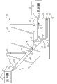
With reference to figure 2, it shows the schematic diagram of continuous liquid printhead 30.The jet module 48 of printhead 30 is included in array or a plurality of nozzle 50 of the nozzle 50 that forms in the nozzle plate 49.In Fig. 2, nozzle plate 49 mounts jet module 48.Yet as shown in Figure 3, nozzle plate 49 can be integrally formed with jet module 48.
Liquid 52, ink for example, each nozzle 50 that passes under pressure in the array sprays to form stream, is commonly called the injection of liquid 52.In Fig. 2, nozzle array or a plurality of nozzle extend in the figure or to the figure extension.
In Fig. 2, droplet-shaped apparatus for converting 28 is the heaters 51 that are arranged in the nozzle plate 49 of nozzle 50 one or both sides, for example, and asymmetric heater or ring heater (segmentation or not segmentation).For example, can be by the U.S. Patent No. 6 of authorizing the people such as Hawkins on November 1st, 2002,457,807 Bl, authorized the U.S. Patent No. 6 of Jeanmaire on December 10th, 2002,491,362 Bl, the U.S. Patent No. 6 that on January 14th, 2003 was authorized the people such as Chwalek, 505,921 B2, the U.S. Patent No. 6 that on April 29th, 2003 was authorized the people such as Jeanmaire, 554,410 B2, authorized the people's such as Jeanmaire U.S. Patent No. 6,575,566 Bl on June 10th, 2003, the U.S. Patent No. 6 that on July 8th, 2003 was authorized the people such as Jeanmaire, 588,888 B2, authorized the U.S. Patent No. 6,793 of Jeanmaire, 328B2 on September 21st, 2004, the U.S. Patent No. 6 that on December 7th, 2004 was authorized the people such as Jeanmaire, 827,429 B2 and authorized some one or more aspect among the people's such as Jeanmaire U.S. Patent No. 6,851,796 B2 on February 8th, 2005 and understand such drop and form.
Usually, a droplet-shaped apparatus for converting 28 is associated with each nozzle 50 of nozzle array.Yet droplet-shaped apparatus for converting 28 can be associated with all nozzles 50 of many groups nozzle 50 or nozzle array.
When printhead 30 work, drop 54,56 produces with sizes or volume usually, for example, and with the form of large drop 56 with first size or volume with have the form of the droplet 54 of the second size or volume.The quality of large drop 56 and the mass ratio of droplet 54 are approximately an integer between 2 to 10 usually.Comprise that drop 54,56 stream of liquid droplets 58 move along droplet path or track 57.
The impact that droplet 54 is subject to air-flow is larger than large drop 56, so droplet track 66 departs from large droplet trajectory 68.That is, the deflection angle of droplet 54 is greater than the deflection angle of large drop 56.Air-flow 62 provides enough drop deflections, trap 42(is as shown in figures 1 and 3 thereby droplet track and large droplet trajectory are enough separated) can be positioned, with one in blocking-up droplet track 66 and the large droplet trajectory 68, so that the drop that trap 42 is collected along this track, and avoid this trap and clash into recording medium 32(as shown in figures 1 and 3 along the drop of other tracks).
When trap 42 was positioned to block large droplet trajectory 68, droplet 54 was contacted with trap 42 and clashes into print record medium 32 avoiding by abundant deflection.When droplet was printed, this situation was called as the droplet printing model.When trap 42 was positioned to block droplet track 66, large drop 56 was printed droplets.This situation is called as large drop printing model.
With reference to figure 3, jet mode 48 comprises array or a plurality of nozzle 50 of nozzle 50.The liquid that provides by passage 47(as shown in Figure 2) (for example, ink) each nozzle 50 by array under pressure sprays, to form stream or the injection of liquid 52.In Fig. 3, the array of nozzle 50 or a plurality of nozzle 50 extend in the figure or to the figure extension.
The drop excitation that is associated with jet module 48 or droplet-shaped apparatus for converting 28(are as depicted in figs. 1 and 2) be selectively activated, with stream or the injection of disturbance liquid 52, thereby the disengaging from stream of a plurality of parts of guiding stream forms drop.In this way, drop selectively produces with the large drop of advancing towards recording medium 32 or the form of droplet.
The positive pressure gas flow structure 61 of air flow deflector mechanism 60 is positioned at the first side of droplet trajectory 57.Positive pressure gas flow structure 61 comprises the first airflow line 72, and this first airflow line 72 comprises lower wall 74 and upper wall 76.The air-flow 62 that airflow line 72 guiding is provided by positive pressure source 92 is with respect to the downward inclination angle theta of about 45 degree of the stream of liquid 52 towards drop deflection zone 64(as shown in Figure 2).Optional sealing device 84 provides aeroseal between the upper wall 76 of jet module 48 and airflow line 72.
The upper wall 76 of airflow line 72 does not need to extend to drop deflection zone 64(as shown in Figure 2).In Fig. 3, upper wall 76 ends at the wall 96 of jet module 48.The wall 96 of jet module 48 is as the part of the upper wall 76 that ends at drop deflection zone 64.
The negative-pressure air-flow structure 63 of air flow deflector mechanism 60 is positioned at the second side of droplet trajectory 57.The negative-pressure air-flow structure comprises the second airflow line 78 between trap 42 and upper wall 82, and this second airflow line 78 is discharged air-flow from deflection area 64.Second pipe 78 is connected to negative pressure source 94, and this negative pressure source 94 is used for helping to remove the gas that flows through second pipe 78.Optionally, sealing device 84 provides aeroseal between jet module 48 and upper wall 82.
As shown in Figure 3, air flow deflector mechanism 60 comprises positive pressure source 92 and negative pressure source 94.Yet according to the application-specific of considering, air flow deflector mechanism 60 can only comprise in positive pressure source 92 and the negative pressure source 94.
The gas that is provided by the first airflow line 72 is directed into drop deflection zone 64, at this place so that large drop 56 along large droplet trajectory 68 and droplet 54 along droplet track 66.As shown in Figure 3, droplet track 66 is caught front 90 blocking-up of storage 42.Droplet 54 contact is positive 90, and along in the positive 90 downward influent Returning pipes 86, this liquid Returning pipe 86 or be formed between trap 42 and the plate 88.Collected liquid or be recovered and return to ink storing device 40 recycling (as shown in Figure 1) or be dropped.Large drop 56 is avoided trap 42 and is continued to march to recording medium 32.Alternately, trap 42 can be positioned to block large droplet trajectory 68.Large drop 56 contact traps 42 also flow into the liquid Returning pipe that is positioned at or is formed at trap 42.Collected liquid or be recycled or be dropped.Droplet 54 is avoided trap 42 and is continued to march to recording medium 32.
Alternately, can asymmetricly heat realization deflection by the stream that utilizes 51 pairs of liquid 52 of asymmetric heater.When being used for this function, asymmetric heater 51 is usually except also forming mechanism as drop as deflection mechanism.Such drop forms and deflection is known, for example, has authorized description in the people's such as Chwalek the U.S. Patent No. 6,079,821 on June 27th, 2000.Should be appreciated that these deflections are the different of the unwanted deflection that specially produces and produce from particle contamination by the printhead filter.
Alternately, can applying by the stream silk that utilizes 51 pairs of liquid 52 of asymmetric heater asymmetricly, heating realizes deflection.When being used for this function, asymmetric heater 51 is usually except also forming mechanism as drop as deflection mechanism.Such drop forms and deflection is known, for example, has authorized description in the people's such as Chwalek the U.S. Patent No. 6,079,821 on June 27th, 2000.
Also can utilize electrostatic deflection mechanisms to realize deflection.Usually, electrostatic deflection mechanisms or picture U.S. Patent No. 4,636, described in 808 like that, drop charge and drop deflection are combined in the single electrode, perhaps comprise independent drop charge electrode and independent deflecting electrode.
As shown in Figure 3, trap 42 is traps of a kind of being commonly called " wall-attachment (Coanda) " trap.Yet " wall-attachment " trap shown in " knive-edge " trap shown in Fig. 1 and Fig. 3 is interchangeable and effectively same.Alternately, trap 42 can be any suitable design, includes but not limited to porous area (porous face) trap, limits edge (delimited edge) trap or above-mentioned any combination.
Fig. 4 A is the cross-sectional side view of jet module 48 that comprises the printhead 30 of an example embodiment of the present invention.Particularly, show the cross-sectional view of nozzle plate 49 and passage 47.For the sake of clarity, not shown various other structures that comprise droplet-shaped apparatus for converting 28/ heater 51.In this example embodiment, form in the independent parts of passage 47 in being incorporated into jet module 48.Particularly, passage 47 is formed by substrate 87.
In this example embodiment, each fluid chamber 53 is positioned, to be communicated with single different spray nozzles fluid in the nozzle 50.Each fluid chamber 53 is limited by the chamber that wall is arranged that is limited by wall 55 at least in part.Each wall 55 extends to filter membrane 100 from nozzle plate 49, and helps to limit fluid chamber 53, and fluid chamber 53 is positioned between nozzle plate 49 and the filter membrane 100.Except being communicated with respective nozzle fluid in a plurality of nozzles 50, each fluid chamber 53 of a plurality of fluid chamber 53 also is communicated with following a plurality of holes 110 fluids with the respective aperture cluster 120 in a plurality of holes cluster 120 of the filter membrane 100 described in detail.
Each has the chamber of wall to adopt to comprise the various forms of the chamber that wall is arranged that limits circular, rectangle and the elliptic space.Fluid chamber 53 of the present invention can provide multiple advantage.For example, fluid chamber 53 acoustics that can be used to reduce between the nozzle 50 is crosstalked.The chamber that wall is arranged that is used for restriction fluid chamber 53 can be used to provide support structure for a plurality of printing head assemblies.As non-limiting example, the support structure of increase need to be born the rigor condition of manufacturing process.
Fig. 4 B has schematically shown the plan cross-sectional view of the jet module 48 that comprises another example embodiment of the present invention.In this example embodiment, filter membrane 100 comprise be positioned to cross over or " bridge joint " fluid chamber 53(namely, shown in broken lines fluid chamber 53 and nozzle 50) plane institution movement.Be suitable for a plurality of holes 110 that particle matter filters from the liquid 52 of continuous-flow are shown as being positioned in the plane institution movement.Each hole 110 can comprise the multiple section shape of the liquid 52 that is suitable for filtering continuous-flow.For example, show the hole 110 that comprises circular section shape.The size in hole 110 can change according to measurement or the expectation size of the particulate in the liquid 52.Circular port 110 can comprise the hole of about 4 micron diameters, but also allows the hole of other shapes, size and arrangement mode.In some example embodiment, the area that the size in hole 110 is designed such that each hole 110 is less than half of each nozzle 50 area.In the embodiment shown, when comparing with other holes in a plurality of holes 110, each in a plurality of holes 110 has unified size.Each hole 110 forms the opening that passes filter membrane 100.The path of the liquid 52 of continuous-flow of flowing through in path and each nozzle 50 of liquid 52 of continuous-flow in each hole 110 is parallel.For convenience's sake, provide reference axis X-axis and Y-axis.In this case, Y-axis is along the axle orientation of the array of nozzle 50, and X-axis is configured to and this direction quadrature.In some example embodiment, X-axis is along the direction of relative movement setting between recording medium 32 and the printhead 30.For example, this direction of relative movement can join with the directional correlation of mobile network (moving web).
With reference to figure 5A and Fig. 5 B, hole 110 is incorporated into together in a plurality of holes cluster 120.Each hole cluster 120 is associated with respective nozzle in the nozzle 50.Hole cluster 120 can comprise a plurality of Confucius's clusters 125 that are associated with each nozzle 50.Hole 110 in the hole cluster 120 can be arranged with rule or random fashion.Each cluster 120 is positioned to allow liquid 52 hole 110 by cluster 120 under pressure to flow into the fluid chamber 53 that is associated, and the final nozzle 50 that is associated that flows into, and liquid 52 sprays from this nozzle 50.Should be appreciated that each cluster 120 is not limited to two Confucius's clusters 125, and Confucius's cluster 125 that can comprise in other embodiments of the invention other suitable quantities.
The quantity in employed hole 110 and size are changeable in each embodiment of the present invention in each hole cluster 120.Usually, each hole cluster 120 comprises the hole 110 of sufficient amount, blocks gradually during filtering and can not adversely affect liquid with a small amount of hole in the cluster of permission hole and flow out from nozzle 50.The quantity in employed hole 110 can be designed to, even a small amount of hole in the cluster of hole is blocked gradually, also can solve the flow impedance by hole 110, and solves thus the pressure drop on the thermal excitation film 100.Can be according to the measurement of the particulate in the liquid 52 or the hole 110 of the definite suitable quantity of pre-metering.Pressure drop is flow through the hole 110 of filter membrane 100 along with the liquid 52 of continuous-flow and is risen.Wish that these pressure drops are lowered as much as possible.The pressure drop that the quantity in the hole 110 of comprise the key element of the quantity in employed hole 110 and size, expection being blocked during filtering and the thickness of filter membrane 100 can bear the duration of work at printhead 30 has significant impact.At some embodiment, when from by sub-cluster 125 the perpendicular plane of the direction in path of liquid 52 of continuous-flow in each hole 110 when watching, the size of selecting hole 110 so that the pressure drop of passing the hole 110 in the sub-cluster 125 less than 1/5 of the pressure drop of passing the nozzle 50 that is associated.In certain embodiments, select the thickness of filter membrane 100 so that the pressure drop of passing the hole 110 in the sub-cluster 125 less than 1/5 of the pressure drop of passing the nozzle 50 that is associated.
Keep the degree of required direction to be commonly called " injection glacing flatness " from the injection of the liquid 52 of nozzle 50 emission.The importance of spraying glacing flatness is because its quality with the image that is produced by the continous inkjet print system is relevant.In some cases, spray deflection preferably is not more than 0.50 degree.In other cases, spray deflection preferably is not more than 0.25 degree.In the other situation, spray deflection preferably is not more than 0.05 degree or less.Many factors can cause the unwanted spray deflection deviation that deviates from mutually with the demand of spraying glacing flatness.For example, the obstruction in a plurality of holes 110 of filter membrane 100 can cause the unwanted deviation from the injection of the liquid 52 of different nozzles 50 ejections.Determined when a plurality of holes 110 by liquid 52 in particle matter when blocking gradually, the distance between filter membrane 100 and the nozzle plate 49 has appreciable impact to the injection glacing flatness.When distance for approximately several microns the time, as using the MEMS technology with nozzle plate 49 and filter membrane 100 as a whole in the situation of unit formation, this impact is especially remarkable.
With reference to Fig. 5 A and Fig. 5 B, show cutting plane figure and the side view of nozzle 50 and the part of the filter membrane 100 with hole cluster 120 special constructions.Each cutting plane figure with the set X-axis of above-mentioned restriction and Y-axis as a reference.Fig. 5 A shows hole cluster 120 structures that are included in a plurality of holes 110 of arranging in even mode on fluid chamber 53 and the nozzle 50.In this case, hole 110 is being evenly distributed along the distance L of X-axis with along the distance W of Y-axis.In Fig. 5 A, the one or more holes 110 in the hole cluster 120 are shown in dotted line with nozzle 50() overlapping.In Fig. 5 B, hole cluster 120 structures comprise by filter membrane 100 without bore portion 130 along X-axis two Confucius's clusters 125 spaced apart from each other.In this case, hole 110 is being evenly distributed along the distance L of X-axis with along the distance W of Y-axis.In this case, two Confucius's clusters 125 are located so that without bore portion 130 and nozzle 50(shown in the dotted line in the plane) overlapping.
Experimental result comprises following observed result.When one or more holes 110 of hole cluster 120 were blocked by particulate gradually, than larger spacing H, larger spray deflection (for example, at directions X) was associated with less spacing H.For giving determining deviation H, the size of the spray deflection that is associated with the hole cluster arrangement of Fig. 5 B is generally less than the size of the spray deflection that is associated with the hole cluster topology of Fig. 5 A.These reduced levels are usually with especially general by the directions X of the directional correlation connection that relatively moves of the recording medium 32 of printhead prints of the present invention.When using more closely-spaced H, these reduced levels are especially general.In some cases, with half less than the spray deflection that is associated with the hole cluster 120 of Fig. 5 A of the spray deflection of hole cluster 120 structurally associateds of Fig. 5 B connection.Therefore, when using very little nozzle plate 49 to the distance H of filter membrane 100, hole cluster 120 structures of Fig. 5 B are in that to reduce spray deflection especially effective aspect horizontal.No matter use the hole cluster topology shown in Fig. 5 A or Fig. 5 B, little nozzle plate 49 comprises that to the spacing of filter membrane 100 width with filter membrane partition distance H is D
NNozzle, 0.5D wherein
N<H<5D
N(that is, D
NThe size of the nozzle 50 of above-mentioned restriction).
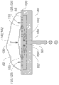
Although the present invention is not retrained by any particular theory, the below will describe the observed result that the hole cluster 120 of Fig. 5 B why can reduce the spray deflection that is caused by the obstruction in hole 110.It is believed that since near and advance longer path crooked without the stream of the liquid 52 of bore portion 130 with the hole 110 by adjacent holes sub-cluster 125, the disturbance in the liquid 52 of continuous-flow has increased time and the distance that tends towards stability.
With reference to figure 6, it is believed that the liquid 52 of continuous-flow is directed to filter membrane 100 so that the part of liquid 52 flows along the first path 140, as the liquid part near filter membrane 100.In this case, extend along the first direction 142 that the entrance with nozzle 50 intersects in the first path 140.Be positioned to block the liquid 52 of continuous-flow without bore portion 130, and change liquid 52 this part direction so that its away from the first path 140, and so that this part of liquid 52 enters the different holes 110 of filter membrane 100.This part of liquid 52 enters fluid chamber 53, and is redirected as along the second path 150 with the durection component 152 that intersects with first direction 142.Therefore, can in fluid chamber 53, produce the substantially stream of equal and rightabout liquid 52 with respect to Confucius's clusters 125 of the symmetrical location of nozzle 50.Rightabout stream can cause strong deflection in properties of flow, this strong deflection overcomes any disturbance of being blocked in the caused stream by one or more holes 110.
Without limits, other reasons can be additionally or is alternatively produced these effects.Can activate the use of particular bore cluster 120 structures of example embodiment of the present invention to the different reasons such as spacing H of filter membrane 100 by comprising required nozzle plate 49.In certain embodiments, use particular bore cluster 120 structures according to nozzle plate 49 to the spacing H of filter membrane 100 at least, wherein, H is from by 0.5D
N<H<5D
NSelect (that is, D in the restricted portion
NThe size of the nozzle 50 of above-mentioned restriction).
Fig. 7 shows expression according to the flow chart for the manufacture of the method 300 of integrated nozzle plate 49/ filter membrane Unit 100 of an example embodiment of the present invention.For convenience's sake, Fig. 8 A, 8B, 8C, 8D and 8F additionally schematically show and a plurality of processing steps that are associated by the represented method of the flow chart of Fig. 7.In step 310, provide the substrate 160 shown in Fig. 8 A.In this embodiment, substrate 160 comprises semi-conducting material (for example, silicon).Substrate 160 comprises the etching stop layer 162 that is positioned between semiconductor layer 164A and the 164B.An example of this integrated substrate is the silicon (SOI) on the dielectric substrate.In step 315, use patterning techniques and lithographic technique to be formed on fluid chamber 53A among the semiconductor layer 164A and the hole cluster 120 that is associated in etching stop layer 162.This step can comprise that shielding layer 164A is to utilize positive resistance limiting hole structure.DRIE etch layer 164A a period of time.Then expose and the same photoresist that develops to limit larger fluid chamber zone.DRIE etch chamber zone.The zone with pore structure that before has been etched will be continued with the speed etching approximately identical with cavity region, to keep approximately identical difference in height.Continue the DRIE etching and be through to insulating barrier until bore region is etched.Then can come etch layer 162 by the hole through the DRIE etching among the layer 164A, to limit the hole in the layer 162.Then, wafer is returned with DIRE etching liquid body cavity until insulating barrier.Then, photoresist is removed from layer 164A.
In step 320, shown in Fig. 8 C, for example use packing material 166(, polyimides) fill and the zone of the substrate 160 that planarization is etched in step 315.In step 325, deposited material layer 170 on the planarized surface of substrate 160.The material layer 170 that deposits of patterning and etching subsequently is to form a plurality of nozzles 50 shown in Fig. 8 D.Step 325 also can comprise the manufacturing of droplet-shaped apparatus for converting 28, and this droplet-shaped apparatus for converting 28 comprises the heater 51 adjacent with nozzle 50.U.S. Patent No. 6,943 has been described in 037 and is used for deposited material layer 170 and forms nozzle 50 and the illustrative steps of the droplet-shaped apparatus for converting 28 that is associated, and this paper is incorporated herein by reference.
In step 330, one or more fluid chamber 53B of patterning, and etch into semiconductor layer 164B.Fluid chamber 53B is positioned in the upstream with respect to the hole cluster 120 of the expection flow direction of the liquid in the printhead.Fluid chamber 53B provides the fluid between fluid supply (for example, ink source) and the filter membrane to be communicated with, and the wall 55B among the layer 164B provides support structure.In certain embodiments, single fluid chamber 53B crosses over whole nozzle array, and ink source is provided and is communicated with fluid between the hole cluster 120 that is associated of each nozzle.In step 335, remove packing material 166, to finish integrated nozzle plate shown in Fig. 8 F/filter membrane unit.Only it should be noted that to show manufacture method 300 by example that the order of the step of adding and/or substitute and/or alternative step all within the scope of the invention.
With reference to figure 8F, and get back to Fig. 4 A, show another example embodiment of the present invention.Jet module 48 comprises be suitable for filter 100 that particle matter is filtered from the liquid 52 of continuous-flow.Particularly, jet module 48 comprises filter membrane 100.Filter membrane 100 is suitable for filtering by passage 47(shown in Fig. 4 A) a plurality of parts of the liquid 52 of the continuous-flow that provides.Filter membrane 100 comprises that a plurality of holes 110 of relative to each other locating are to produce hole cluster 120.Hole 110 and hole cluster 120 are suitable for filtering the particle matter in the liquid 52 of continuous-flow.
In this example embodiment, filter 100 comprises the first side 100A and the second side 100B, and this second side 100B is the upstream with respect to liquid flow direction and the first side 100A.In this embodiment, a plurality of walls 55 are a plurality of first wall 55A that extend to the first side 100A of filter 100.A plurality of the second wall 55B from the second side 100B of filter 100 to passage 47(shown in Fig. 4 A) extend.
With reference to figure 8F, each fluid chamber 53A is positioned to be communicated with single different spray nozzles 50 fluids in the nozzle 50.Each fluid chamber 53A is limited by the chamber that wall is arranged that is limited by wall 55A at least in part.Each wall 55A extends to filter membrane 100 and helps to limit fluid chamber 53A from substrate 85, and described fluid chamber 53A is positioned between substrate 85 and the filter membrane 100.Except being communicated with respective nozzle fluid in a plurality of nozzles 50, each fluid chamber 53A of a plurality of fluid chamber 53A also is communicated with a plurality of holes 110 fluids of respective aperture cluster 120 in a plurality of holes cluster 120 of filter 100 described above in detail.
A plurality of the second wall 55B limit a plurality of liquid service duct 53B, and each liquid service duct 53B is communicated with respective liquid chamber fluid among a plurality of fluid chamber 53A by one in a plurality of holes cluster 120.Liquid service duct 53B and fluid chamber 53A can be substantially with a plurality of nozzles 50 in the respective nozzle conllinear.Liquid service duct 53B also with service duct 47(shown in Fig. 4 A) fluid is communicated with.Alternately, each liquid service duct 53B can be communicated with a plurality of fluid chamber 53A fluids by the hole cluster 120 that is associated with each fluid chamber 53A.
With reference to figure 9A and Fig. 9 B, and return Fig. 8 F and 4A, show additional embodiment of the present invention.Nozzle 50 is with arrayed, and this array is one dimension or two-dimensional linear array normally.Shown in Fig. 9 A and Fig. 9 B, the array of nozzle 50 is in each figure and the figure extension.Fluid chamber 53A comprises the first width 350 of measuring perpendicular to the axis 358 of nozzle 50.Liquid service duct 53B comprises the second width 352 of measuring perpendicular to nozzle-axis 358.When comparing with the second width 352, the first width 350 is different.The first width 350 is less than the second width 352, and this helps to limit supporting construction 356, and this supporting construction 356 provides additional stability and hardness for filter 100.Shown in Fig. 9 A, fluid chamber 53A also comprises the 3rd width 354 of measuring perpendicular to nozzle-axis 358, and the 3rd width 354 is downstreams with respect to the first width 352.The 3rd width 354 is greater than the first width 350.This helps to limit supporting construction 356, and this supporting construction 356 provides sufficient properties of flow and increases the contact area (for example, when comparing with the supporting construction 356 shown in Fig. 9 B) that contacts with filter 100.Can form the fluid chamber 53A shown in Fig. 9 A, produce the wall 55A of inclination with the etchant of anisotropic etching method utilization such as KOH or tetramethyl amine (TMAH) by silicon materials.When the example embodiment shown in Fig. 8 F, 9A and the 9B comprised the filter type of Fig. 4 A and 5A, alternative example embodiment comprised, for example the filter type shown in Fig. 4 B and the 5B.
Embodiments of the invention advantageously allow forming of the integrated nozzle plate that formed by single substrate/filter membrane unit.Embodiments of the invention advantageously allow the use of MEMS manufacturing technology, and this has reduced the particle contamination that is associated with other manufacturing technologies fully.Embodiments of the invention advantageously allow to have the formation of the integrated nozzle plate of acceptable nozzle linearity/filter membrane unit.
Parts List
20 continous inkjet printers systems
22 image sources
24 graphics processing units
26 mechanism control circuits
28 droplet-shaped apparatus for converting
30 printheads
32 recording mediums
34 recording medium transmission systems
36 recording mediums control transmission system
38 microcontrollers
40 liquid reservoirs
42 traps
44 recovery units
46 pressure regulators
47 passages
48 jet modules
49 nozzle plates
More than 50 nozzle
51 heaters
52 liquid
53 fluid chamber
The 53A fluid chamber
The 53B fluid passage
54 drops
The 55A wall
The 55B wall
56 drops
57 tracks
58 stream of liquid droplets
60 air flow deflector mechanisms
61 positive pressure gas flow structures
62 air-flows
63 negative-pressure air-flow structures
64 deflecting regions
66 droplet tracks
68 large droplet trajectory
72 first airflow lines
74 lower walls
76 upper walls
78 second airflow lines
82 upper walls
84 sealing devices
85 substrates
86 liquid Returning pipes
87 substrates
88 plates
90 fronts
92 positive pressure source
94 negative pressure sources
96 walls
98 semi-conducting materials
100 filter membranes
110 holes
120 hole clusters
125 Confucius's clusters
130 without bore portion
140 first paths
142 first directions
150 second paths
152 durection components
160 substrates
162 etching stop layers
The 164A semiconductor layer
The 164B semiconductor layer
166 packing materials
170 material layers
200 traditional continous inkjet heads
249 nozzle plates
250 nozzles
252 liquid
253 streams
255 fluid chamber
260 liquid supply manifolds
270 filters
280 holes
300 methods
310 provide a substrate
The 315 hole clusters that form fluid chamber and be associated
320 fill also planarization through etch areas
325 provide material layer at planarized surface
330 form time fluid chamber
335 remove packing material
350 first width
352 second width
354 the 3rd width
356 supporters
The X axle
The Y axle
The W distance
The L distance
D
NJet size
The H interval
Claims (12)
1. printhead comprises:
Nozzle plate, a plurality of parts of described nozzle plate limit a plurality of nozzles;
Filter membrane, described filter membrane comprise a plurality of holes that are grouped into a plurality of holes cluster; And
A plurality of walls, in described a plurality of wall each extends to filter membrane from nozzle plate, be positioned in a plurality of fluid chamber between described nozzle plate and the filter membrane with restriction, each fluid chamber of described a plurality of fluid chamber is communicated with respective nozzle fluid in a plurality of nozzles, a plurality of orifice flow bodies of the respective aperture cluster in each fluid chamber of described a plurality of fluid chamber and a plurality of holes cluster are communicated with, the respective aperture cluster in the cluster of described a plurality of holes comprise by described filter membrane without bore portion apart from one another by two Confucius's clusters.
2. printhead as claimed in claim 1, the aliging with the respective nozzle in a plurality of nozzles without bore portion of wherein said filter membrane is so that the respective nozzle conllinear in a plurality of nozzles of a plurality of Kong Buyu of the respective aperture cluster in the cluster of described a plurality of holes.
3. printhead as claimed in claim 1, wherein said two Confucius's clusters are symmetrically arranged with respect to the respective nozzle in a plurality of nozzles.
4. printhead as claimed in claim 1, described filter membrane comprises the first side and the second side, and described a plurality of walls are more than first walls that extend to the first side of filter membrane, and described printhead also comprises:
More than second wall that extends from the second side of filter membrane.
5. printhead as claimed in claim 4, wherein each in each in a plurality of liquid service ducts and a plurality of fluid chamber substantially with a plurality of nozzles in the respective nozzle conllinear.
6. printhead as claimed in claim 1, each nozzle of described a plurality of nozzles has an area, and each hole in described a plurality of holes has an area, and wherein the area in each hole is less than half of each nozzle area.
7. printhead as claimed in claim 1, each nozzle of described a plurality of nozzles has a width D
N, described filter membrane and described a plurality of nozzle spacing distance H, wherein 0.5D
N<H<5D
N
8. printhead as claimed in claim 1, each of wherein said a plurality of holes has identical size and dimension.
9. printhead as claimed in claim 1, the hole of wherein said hole cluster is parallel with respect to the respective nozzle in a plurality of nozzles.
10. printhead as claimed in claim 1, wherein said filter membrane is made by the first material, and described a plurality of wall is to be made by the second material, and described the second material is different from described the first material.
11. printhead as claimed in claim 1 further comprises:
By the fluid supply that the respective aperture cluster in each fluid chamber and a plurality of holes cluster that is associated with each fluid chamber is communicated with each fluid nozzle of a plurality of nozzles, described fluid supply is configured to provide liquid under the pressure that is enough to atomizing of liquids sprayed by each nozzle.
12. printhead as claimed in claim 10, described filter membrane has thickness at liquid flow direction, select described thickness so that the pressure drop by a plurality of holes in the cluster of hole less than by 1/5 of injection differential pressure.
Applications Claiming Priority (3)
| Application Number | Priority Date | Filing Date | Title |
|---|---|---|---|
| US12/767,822 US8534818B2 (en) | 2010-04-27 | 2010-04-27 | Printhead including particulate tolerant filter |
| US12/767,822 | 2010-04-27 | ||
| PCT/US2011/033024 WO2011136978A1 (en) | 2010-04-27 | 2011-04-19 | Printhead including particulate tolerant filter |
Publications (1)
| Publication Number | Publication Date |
|---|---|
| CN102858544A true CN102858544A (en) | 2013-01-02 |
Family
ID=44065675
Family Applications (1)
| Application Number | Title | Priority Date | Filing Date |
|---|---|---|---|
| CN2011800214575A Pending CN102858544A (en) | 2010-04-27 | 2011-04-19 | Printhead including particulate tolerant filter |
Country Status (6)
| Country | Link |
|---|---|
| US (1) | US8534818B2 (en) |
| EP (1) | EP2563592A1 (en) |
| JP (1) | JP2013525155A (en) |
| CN (1) | CN102858544A (en) |
| BR (1) | BR112012024533A2 (en) |
| WO (1) | WO2011136978A1 (en) |
Cited By (3)
| Publication number | Priority date | Publication date | Assignee | Title |
|---|---|---|---|---|
| CN105620048A (en) * | 2014-11-26 | 2016-06-01 | 杭州费尔过滤技术有限公司 | Square jet ink filter |
| CN110239221A (en) * | 2018-03-09 | 2019-09-17 | 中国科学院苏州纳米技术与纳米仿生研究所 | A kind of inkjet-printing device |
| CN115097696A (en) * | 2022-08-26 | 2022-09-23 | 天霖(张家港)电子科技有限公司 | Optimize gummed developing machine |
Families Citing this family (4)
| Publication number | Priority date | Publication date | Assignee | Title |
|---|---|---|---|---|
| US8651632B2 (en) * | 2012-03-20 | 2014-02-18 | Eastman Kodak Company | Drop placement error reduction in electrostatic printer |
| US8991986B2 (en) * | 2012-04-18 | 2015-03-31 | Eastman Kodak Company | Continuous inkjet printing method |
| US8882254B2 (en) * | 2012-05-03 | 2014-11-11 | Fujifilm Corporation | Systems and methods for delivering and recirculating fluids |
| US9630419B2 (en) | 2012-09-12 | 2017-04-25 | Funai Electric Co., Ltd. | Maintenance valve for fluid ejection head |
Citations (7)
| Publication number | Priority date | Publication date | Assignee | Title |
|---|---|---|---|---|
| US4638327A (en) * | 1985-04-08 | 1987-01-20 | Burlington Industries, Inc. | Apparatus to damp turbulence in an ink jet fluid supply chamber |
| US20030081082A1 (en) * | 2001-10-31 | 2003-05-01 | Eastman Kodak Company | Continuous ink-jet printing apparatus having an improved droplet deflector and catcher |
| US6793328B2 (en) * | 2002-03-18 | 2004-09-21 | Eastman Kodak Company | Continuous ink jet printing apparatus with improved drop placement |
| US6827429B2 (en) * | 2001-10-03 | 2004-12-07 | Eastman Kodak Company | Continuous ink jet printing method and apparatus with ink droplet velocity discrimination |
| EP1537997A1 (en) * | 2003-12-01 | 2005-06-08 | Brother Kogyo Kabushiki Kaisha | Inkjet head, filter plate for inkjet head, and method of manufacturing filter plate |
| US20060055739A1 (en) * | 2004-09-13 | 2006-03-16 | Kim Kwang-Ryul | Filter plate usable with an ink jet head, an ink jet head with the filter plate, and a method of fabricating the filter plate |
| US20070229608A1 (en) * | 2004-05-04 | 2007-10-04 | Steiner Thomas W | Method and Print Head for Flow Conditioning a Fluid |
Family Cites Families (45)
| Publication number | Priority date | Publication date | Assignee | Title |
|---|---|---|---|---|
| JPS5269628A (en) | 1975-12-08 | 1977-06-09 | Hitachi Ltd | Ink jet recorder |
| JPS61188160A (en) * | 1985-02-18 | 1986-08-21 | Ricoh Co Ltd | Ink jet head |
| US4636808A (en) | 1985-09-09 | 1987-01-13 | Eastman Kodak Company | Continuous ink jet printer |
| US4639748A (en) | 1985-09-30 | 1987-01-27 | Xerox Corporation | Ink jet printhead with integral ink filter |
| US5124717A (en) | 1990-12-06 | 1992-06-23 | Xerox Corporation | Ink jet printhead having integral filter |
| US5204690A (en) | 1991-07-01 | 1993-04-20 | Xerox Corporation | Ink jet printhead having intergral silicon filter |
| US5141596A (en) | 1991-07-29 | 1992-08-25 | Xerox Corporation | Method of fabricating an ink jet printhead having integral silicon filter |
| JPH06255101A (en) * | 1993-03-03 | 1994-09-13 | Seiko Epson Corp | Ink jet recording head |
| US5489930A (en) | 1993-04-30 | 1996-02-06 | Tektronix, Inc. | Ink jet head with internal filter |
| JP3492441B2 (en) | 1994-03-15 | 2004-02-03 | ゼロックス・コーポレーション | Thermal inkjet printbar valve connector and ink handling system |
| AUPO793797A0 (en) | 1997-07-15 | 1997-08-07 | Silverbrook Research Pty Ltd | A method of manufacture of an image creation apparatus (IJM03) |
| US6139674A (en) | 1997-09-10 | 2000-10-31 | Xerox Corporation | Method of making an ink jet printhead filter by laser ablation |
| US6079821A (en) | 1997-10-17 | 2000-06-27 | Eastman Kodak Company | Continuous ink jet printer with asymmetric heating drop deflection |
| US6264309B1 (en) | 1997-12-18 | 2001-07-24 | Lexmark International, Inc. | Filter formed as part of a heater chip for removing contaminants from a fluid and a method for forming same |
| US6267251B1 (en) | 1997-12-18 | 2001-07-31 | Lexmark International, Inc. | Filter assembly for a print cartridge container for removing contaminants from a fluid |
| US6086195A (en) * | 1998-09-24 | 2000-07-11 | Hewlett-Packard Company | Filter for an inkjet printhead |
| US6309054B1 (en) | 1998-10-23 | 2001-10-30 | Hewlett-Packard Company | Pillars in a printhead |
| US6234623B1 (en) | 1999-06-03 | 2001-05-22 | Xerox Corporation | Integral ink filter for ink jet printhead |
| EP1095776B1 (en) | 1999-10-29 | 2006-10-04 | Eastman Kodak Company | Improved ultrasonic cleaning system in ink jet printing systems |
| US6582064B2 (en) | 2000-06-20 | 2003-06-24 | Hewlett-Packard Development Company, L.P. | Fluid ejection device having an integrated filter and method of manufacture |
| US6554410B2 (en) | 2000-12-28 | 2003-04-29 | Eastman Kodak Company | Printhead having gas flow ink droplet separation and method of diverging ink droplets |
| US6505921B2 (en) | 2000-12-28 | 2003-01-14 | Eastman Kodak Company | Ink jet apparatus having amplified asymmetric heating drop deflection |
| US6588888B2 (en) | 2000-12-28 | 2003-07-08 | Eastman Kodak Company | Continuous ink-jet printing method and apparatus |
| US6502925B2 (en) | 2001-02-22 | 2003-01-07 | Eastman Kodak Company | CMOS/MEMS integrated ink jet print head and method of operating same |
| US6457807B1 (en) | 2001-02-16 | 2002-10-01 | Eastman Kodak Company | Continuous ink jet printhead having two-dimensional nozzle array and method of redundant printing |
| JP4006957B2 (en) * | 2001-05-31 | 2007-11-14 | ブラザー工業株式会社 | Inkjet head |
| US6685299B2 (en) * | 2001-05-31 | 2004-02-03 | Brother Kogyo Kabushiki Kaisha | Ink jet head |
| US6923530B2 (en) | 2001-06-13 | 2005-08-02 | Nu-Kote International, Inc. | Fused filter screen for use in ink jet cartridge and method of assembling same |
| US6491362B1 (en) | 2001-07-20 | 2002-12-10 | Eastman Kodak Company | Continuous ink jet printing apparatus with improved drop placement |
| US6611085B1 (en) | 2001-08-27 | 2003-08-26 | Sandia Corporation | Photonically engineered incandescent emitter |
| US6626522B2 (en) | 2001-09-11 | 2003-09-30 | Hewlett-Packard Development Company, L.P. | Filtering techniques for printhead internal contamination |
| US6769765B2 (en) | 2002-07-22 | 2004-08-03 | Xerox Corporation | Filter with integral heating element |
| US6575566B1 (en) | 2002-09-18 | 2003-06-10 | Eastman Kodak Company | Continuous inkjet printhead with selectable printing volumes of ink |
| US6916090B2 (en) | 2003-03-10 | 2005-07-12 | Hewlett-Packard Development Company, L.P. | Integrated fluid ejection device and filter |
| JP2004268454A (en) * | 2003-03-10 | 2004-09-30 | Brother Ind Ltd | Inkjet head |
| US7101030B2 (en) | 2003-05-21 | 2006-09-05 | Xerox Corporation | Formation of novel ink jet filter printhead using transferable photopatterned filter layer |
| US6905198B2 (en) | 2003-07-24 | 2005-06-14 | Hewlett-Packard Development Company, L.P. | Liquid supply vessel |
| US7018032B2 (en) | 2004-01-08 | 2006-03-28 | Fuji Xerox Co., Ltd. | Internal venting structure for fluid tanks |
| JP4507170B2 (en) * | 2004-02-23 | 2010-07-21 | ブラザー工業株式会社 | Inkjet printer head |
| US7192131B2 (en) * | 2004-05-12 | 2007-03-20 | Hewlett-Packard Development Company, L.P. | Filter element carrier, filter, ink pen |
| JP2006231812A (en) * | 2005-02-28 | 2006-09-07 | Ricoh Co Ltd | Recording head and ink-jet recording device |
| JP2008254304A (en) * | 2007-04-04 | 2008-10-23 | Canon Inc | Inkjet recording head |
| JP5171454B2 (en) * | 2008-07-23 | 2013-03-27 | 株式会社日立産機システム | Inkjet recording device |
| US8201928B2 (en) * | 2009-12-15 | 2012-06-19 | Xerox Corporation | Inkjet ejector having an improved filter |
| US20110261124A1 (en) * | 2010-04-27 | 2011-10-27 | Baumer Michael F | Printhead including filter associated with each nozzle |
-
2010
- 2010-04-27 US US12/767,822 patent/US8534818B2/en active Active
-
2011
- 2011-04-19 BR BR112012024533A patent/BR112012024533A2/en not_active IP Right Cessation
- 2011-04-19 JP JP2013508029A patent/JP2013525155A/en active Pending
- 2011-04-19 WO PCT/US2011/033024 patent/WO2011136978A1/en active Application Filing
- 2011-04-19 EP EP11717863A patent/EP2563592A1/en not_active Withdrawn
- 2011-04-19 CN CN2011800214575A patent/CN102858544A/en active Pending
Patent Citations (7)
| Publication number | Priority date | Publication date | Assignee | Title |
|---|---|---|---|---|
| US4638327A (en) * | 1985-04-08 | 1987-01-20 | Burlington Industries, Inc. | Apparatus to damp turbulence in an ink jet fluid supply chamber |
| US6827429B2 (en) * | 2001-10-03 | 2004-12-07 | Eastman Kodak Company | Continuous ink jet printing method and apparatus with ink droplet velocity discrimination |
| US20030081082A1 (en) * | 2001-10-31 | 2003-05-01 | Eastman Kodak Company | Continuous ink-jet printing apparatus having an improved droplet deflector and catcher |
| US6793328B2 (en) * | 2002-03-18 | 2004-09-21 | Eastman Kodak Company | Continuous ink jet printing apparatus with improved drop placement |
| EP1537997A1 (en) * | 2003-12-01 | 2005-06-08 | Brother Kogyo Kabushiki Kaisha | Inkjet head, filter plate for inkjet head, and method of manufacturing filter plate |
| US20070229608A1 (en) * | 2004-05-04 | 2007-10-04 | Steiner Thomas W | Method and Print Head for Flow Conditioning a Fluid |
| US20060055739A1 (en) * | 2004-09-13 | 2006-03-16 | Kim Kwang-Ryul | Filter plate usable with an ink jet head, an ink jet head with the filter plate, and a method of fabricating the filter plate |
Cited By (4)
| Publication number | Priority date | Publication date | Assignee | Title |
|---|---|---|---|---|
| CN105620048A (en) * | 2014-11-26 | 2016-06-01 | 杭州费尔过滤技术有限公司 | Square jet ink filter |
| CN110239221A (en) * | 2018-03-09 | 2019-09-17 | 中国科学院苏州纳米技术与纳米仿生研究所 | A kind of inkjet-printing device |
| CN115097696A (en) * | 2022-08-26 | 2022-09-23 | 天霖(张家港)电子科技有限公司 | Optimize gummed developing machine |
| CN115097696B (en) * | 2022-08-26 | 2022-11-18 | 天霖(张家港)电子科技有限公司 | Optimize gummed developing machine |
Also Published As
| Publication number | Publication date |
|---|---|
| BR112012024533A2 (en) | 2017-10-03 |
| US8534818B2 (en) | 2013-09-17 |
| JP2013525155A (en) | 2013-06-20 |
| WO2011136978A1 (en) | 2011-11-03 |
| EP2563592A1 (en) | 2013-03-06 |
| US20110261123A1 (en) | 2011-10-27 |
Similar Documents
| Publication | Publication Date | Title |
|---|---|---|
| CN102858544A (en) | Printhead including particulate tolerant filter | |
| CN102427949B (en) | Printhead With Porous Catcher | |
| US7399068B2 (en) | Continuous ink jet printing apparatus with integral deflector and gutter structure | |
| CN102173205B (en) | Liquid ejection head, inkjet printing apparatus and liquid ejecting method | |
| US7758155B2 (en) | Monolithic printhead with multiple rows of inkjet orifices | |
| CN102256800A (en) | Buttable printhead module and pagewide printhead | |
| TWI568597B (en) | Fluid ejection device with ink feedhole bridge | |
| US8523327B2 (en) | Printhead including port after filter | |
| US20110261124A1 (en) | Printhead including filter associated with each nozzle | |
| CN103079827A (en) | Printhead including reinforced liquid chamber | |
| US20100295912A1 (en) | Porous catcher | |
| US8562120B2 (en) | Continuous printhead including polymeric filter | |
| US8806751B2 (en) | Method of manufacturing printhead including polymeric filter | |
| US8267504B2 (en) | Printhead including integrated stimulator/filter device | |
| US8287101B2 (en) | Printhead stimulator/filter device printing method | |
| US20110204018A1 (en) | Method of manufacturing filter for printhead | |
| US20110261126A1 (en) | Printhead including polymeric filter | |
| CN114728522B (en) | Printhead, device and jet die | |
| US8490282B2 (en) | Method of manufacturing a porous catcher | |
| US8668312B2 (en) | Liquid ejection with on-chip deflection and collection | |
| CN103108754A (en) | Stimulator/filter device that spans printhead liquid chamber | |
| US8277035B2 (en) | Printhead including sectioned stimulator/filter device | |
| US20130286109A1 (en) | Liquid ejection with on-chip deflection and collection |
Legal Events
| Date | Code | Title | Description |
|---|---|---|---|
| C06 | Publication | ||
| PB01 | Publication | ||
| C10 | Entry into substantive examination | ||
| SE01 | Entry into force of request for substantive examination | ||
| C02 | Deemed withdrawal of patent application after publication (patent law 2001) | ||
| WD01 | Invention patent application deemed withdrawn after publication |
Application publication date: 20130102 |