CN102906832A - Transmitter module for use in modular power transmitting system - Google Patents
Transmitter module for use in modular power transmitting system Download PDFInfo
- Publication number
- CN102906832A CN102906832A CN2011800265257A CN201180026525A CN102906832A CN 102906832 A CN102906832 A CN 102906832A CN 2011800265257 A CN2011800265257 A CN 2011800265257A CN 201180026525 A CN201180026525 A CN 201180026525A CN 102906832 A CN102906832 A CN 102906832A
- Authority
- CN
- China
- Prior art keywords
- module
- transmitter
- transmitter module
- electric power
- adjacent
- Prior art date
- Legal status (The legal status is an assumption and is not a legal conclusion. Google has not performed a legal analysis and makes no representation as to the accuracy of the status listed.)
- Granted
Links
Images


Classifications
-
- H—ELECTRICITY
- H01—ELECTRIC ELEMENTS
- H01R—ELECTRICALLY-CONDUCTIVE CONNECTIONS; STRUCTURAL ASSOCIATIONS OF A PLURALITY OF MUTUALLY-INSULATED ELECTRICAL CONNECTING ELEMENTS; COUPLING DEVICES; CURRENT COLLECTORS
- H01R13/00—Details of coupling devices of the kinds covered by groups H01R12/70 or H01R24/00 - H01R33/00
- H01R13/46—Bases; Cases
- H01R13/514—Bases; Cases composed as a modular blocks or assembly, i.e. composed of co-operating parts provided with contact members or holding contact members between them
-
- H—ELECTRICITY
- H01—ELECTRIC ELEMENTS
- H01F—MAGNETS; INDUCTANCES; TRANSFORMERS; SELECTION OF MATERIALS FOR THEIR MAGNETIC PROPERTIES
- H01F38/00—Adaptations of transformers or inductances for specific applications or functions
- H01F38/14—Inductive couplings
-
- H—ELECTRICITY
- H01—ELECTRIC ELEMENTS
- H01F—MAGNETS; INDUCTANCES; TRANSFORMERS; SELECTION OF MATERIALS FOR THEIR MAGNETIC PROPERTIES
- H01F27/00—Details of transformers or inductances, in general
- H01F27/28—Coils; Windings; Conductive connections
- H01F27/2804—Printed windings
Abstract
A modular power transmitting system comprises multiple transmitter modules being connected together for transmitting power inductively to a receiver. The transmitter module is connected with other transmitter modules for transmitting power inductively to the receiver, wherein the transmitter module (40) comprises at least one transmitter cell (30), each transmitter cell having one transmitter coil (33) by which the transmitter cell transmitting power to the receiver, the transmitter module having an outer periphery (45) being shaped so as to fit to neighboring transmitter modules for forming an power transmitting surface, the at least one transmitter cell being arranged such that the power transmitting surface is constituted by an uninterrupted pattern of adjacent transmitter coils extending in said surface, and interconnection units (110,111); for connecting with neighboring transmitter modules for sharing a power supply.
Description
Technical field
The present invention relates to use the field of the power transmission technology of induction wireless electric power transmission (transmission) system, relate more specifically to for use to be used for inductively transferring electric power to the transmitter module of receiver at induction power system.
The invention still further relates to for the tucker module and the expansion module that use at the modularization induction power system.
Background technology
For to the battery charging such as the battery feed apparatus of cell phone, PDA, remote controller, notebook etc., perhaps directly to the power devices such as lamp or kitchen appliance, can application enabled realize that wireless power carries the induction power system of (transfer).For delivery of electric power or usually known to the induction power system of charging of mobile devices.This system comprises the power transmitting device hereinafter referred to as transmitter module, and it comprises can be energized separately the one or more emitter coils that produce thus alternating magnetic field.Induction power system is used to transmit electric power and hereinafter is called the power receiving apparatus of receiver, and this power receiving apparatus can be connected to be charged or the equipment of power supply or the part of this equipment.In order to receive electric power, power receiving apparatus is provided with receiver coil, and the alternating magnetic field that is provided by the emitter coil that is energized is in this receiver coil induced currents.This electric current can drive load or for example battery be charged, to monitor power supply or some bright light.
Document US 7,576,514 have described a kind of plane sense answers batter-charghing system, and it is designed so that electronic equipment can be re-charged electricity.This system comprises electric power surface, plane, and equipment to be recharged is placed on this surface.At least one emitter coil and preferably transmitter coil array be positioned at the electric power surface, this at least one emitter coil and preferably transmitter coil array energy-sensitive is coupled to the receiver coil that in equipment to be recharged, forms.Thereby the various layouts of having described emitter coil provide the uninterrupted electric power surface of the emitter coil with substantial constant density.The application of this array can be for to wireless device power supply, for example is used for being integrated in furniture or as the common electric power surface of the battery charging of floor or wall covering.
Summary of the invention
Known wireless induction electric power system has such problem, and the size of emitter region is scheduled to.Yet in many cases, needed zone may change, and lacks flexibility so that have the system of preliminary dimension.By selecting the coil of proper number, emitter region can be selected as any arbitrary dimension.Yet, subsequently this size be fix and can not expand.If two or more these preliminary dimension systems put together, between the system with leaving gap, because the border of these systems is not to be designed to and will to be combined.In these positions, do not provide rightly operation (for example electric power transfer).Moreover independent system is not designed to cooperate each other.
The purpose of this invention is to provide a kind of transmitter module for using at electrical power transmission system.This transmitter module intention is connected to form this system with other transmitter module, and this system can easily expand to arbitrary dimension and keep simultaneously flexibility.
For this purpose, according to a first aspect of the invention, a kind of transmitter module for using at the modularization induction power system has been proposed.This system comprises transmitter module, and it is connected to be used for inductively transferring electric power to receiver with other transmitter module.Preferably, other transmitter module is identical with this transmitter module aspect shape and coil layout.This will simplify system.This transmitter module comprises at least one transmitter unit, each transmitter unit has an emitter coil, transmitter unit passes through this emitter coil transferring electric power to receiver, this transmitter module has outer peripheral edges, thereby it is formed and is fitted to the adjacent transmitter module to be used to form the electric power transfer surface, this at least one transmitter unit is arranged so that the electric power transfer surface is made of the uninterrupted pattern that adjoins emitter coil of expanding in described surface, this transmitter module comprises interconnecting unit, and it is used for being connected to be used for sharing power supply with the adjacent transmitter module of adjoining in described direction.
The external shape of transmitter unit forms the fine and close pattern that allows to adjoin emitter coil when each unit is arranged side by side.For example, the unit for example be shaped as hexagon or foursquare regular polygon the time, each unit can adjoin and arrange regularly and without any interruption.The outer peripheral edges of module can be made of the sections of transmitter unit shape, and therefore permission is arranged each module abreast on any direction of the basic configuration permission of unit.When number of modules is so arranged, consist of uninterrupted pattern in the zone of transmitter unit and corresponding coil meaning size in office.Distance between the emitter coil always equates, no matter coil is in same inside modules or inner at disparate modules.Utilize this uninterrupted pattern, the user can be placed on receiver any position on electric power transfer surface.In addition, this system can provide the large receiving coil with better efficient to receiver.Interconnecting unit provides power supply to all modules that are arranged side by side easily at least.
In the embodiment of transmitter module, it comprises for the controller of control electric power transfer to receiver, for example is used for the switch unit of each emitter coil of excitation.Controller can enable to realize the self-centered operation of each transmitter module, thus namely this controller can provide local intelligence enable to realize electric power transfer from master control and/or such as other possible function of communicating by letter with receiver.Subsequently, no matter whether have adjacent block, this module can be transported to receiver from master control electric power.The effect that described measure has is for having formed a kind of induction power surface, and it can expand to arbitrary dimension by adding add-on module.
In the embodiment of transmitter module, for the part that consists of outer peripheral edges, this transmitter unit can be according to such as hexagonal regular polygon, perhaps the rule petal shape, any other bending pattern that perhaps has protuberance and recess is shaped, wherein protuberance is fitted to the recess of adjacent transmitter module and the protuberance that recess is fitted to the adjacent transmitter module, enables to realize that the uninterrupted coil along whole electric power surface arranges as long as the outer peripheral edges pattern is fitted to the outer peripheral edges of adjacent block and it.Because uninterrupted coil layout, the variation in the induction field reduces.
In the embodiment of transmitter module, outer peripheral edges also are provided with the extension that is positioned at the first peripheral position and are positioned at the complementary notch of the second peripheral position, and when module arrangement was in the electric power surface, primary importance was adjoined the second place of adjacent block to be used for providing machinery fixing via extension and notch.The mechanical stability that this advantage that has is the electric power surface strengthens.
In the embodiment of transmitter module, when module arrangement was in the electric power surface, interconnecting unit had the configuration of female connectors, was connected with the adjacent transmitter module via the interconnection pin that is parallel to the electric power surface being used for.This advantage that has is that in the outer edge on electric power surface, contact plug is not expanded.
In the embodiment of transmitter module, when module arrangement is in the electric power surface, interconnecting unit has and is arranged in the first peripheral position along periphery and connects and configure to be used for being connected with the complementation that is in the second peripheral position in the adjacent transmitter module electricity that is connected, the first and second location matches when each module is arranged by intention, and does not mate the first and second positions when each module is otherwise arranged, thereby be used for providing Opposite direction connection safety.Should point out, module can be symmetrical at least one position of rotation.The effect that described feature has is, module will have the connection according to intention when suitably arranging, cause interconnecting unit to be positioned at different unmatched positions and module is positioned at the different rotary position, and this is called Opposite direction connection safety.
In the embodiment of transmitter module, interconnecting unit is arranged to be used to the communication connection that provides between this transmitter module and other transmitter module.This effect that has is, the controller swap data between each module that is enabled.For example when receiver strode across the module boundary alignment, it is coordinated that electric power conveying and other task can advantageously stride across each module.
In the embodiment of transmitter module, controller is arranged to for determining position and the orientation of this transmitter module with respect to other transmitter module that is arranged in the electric power surface.In this document transmitter module determine such function: this module and other module communication that is connected via its interconnecting unit, and survey it and where and how be positioned in the electric power surface with respect to other module and locate.This module is with the position and the orientation that oneself are assigned in the electric power surface subsequently.This advantage that has is that each module now can be in response to the order that for example is used for encouraging one or more specific receivers of ad-hoc location in the indication electric power surface.
In the embodiment of transmitter module, transmitter module comprises memory, its be used for when this module arrangement during on the electric power surface storage be used for identifying the identifying information of this transmitter module.Identifying information can be stored in the permanent memory of hardwired or changeable (for example being set up during manufacture or at erection stage).This advantage that has can be addressed separately for this module.
In one embodiment, the tucker module is provided in the modularization induction power system that limits as mentioned and uses, this tucker module has: at least one outer peripheral edge portion, thereby it is formed and is fitted to adjacent transmitter module formation electric power transfer surface at least one direction, and the outer peripheral edge portion adjacent with each transmitter module is formed according to the outer peripheral edges of adjacent transmitter module; And at least one another periphery, with non-conterminous this another periphery of each transmitter module be straight to be used for to the straight border of electric power surface proof.In the time of in being arranged in the electric power surface, the tucker module advantageously provides straight outer peripheral edges to the electric power surface.
In one embodiment, expansion module is provided in the modularization induction power system that limits as mentioned and uses, this expansion module has: at least one outer peripheral edge portion, thereby it is formed and is fitted to adjacent transmitter module formation electric power transfer surface at least one direction, the outer peripheral edge portion adjacent with each transmitter module is formed according to the outer peripheral edges of adjacent transmitter module, this expansion module comprises be used to the interconnecting unit that provides power supply to arrive the adjacent transmitter module, perhaps is used for control and strides across the electric power conveying of different transmitter modules or the system controller of communication; Perhaps be used for enabling to control the electric power conveying that strides across different transmitter modules or the operation-interface of communicating by letter; Perhaps be used for enabling to stride across the data conveying of different transmitter modules or this receiver or the data-interface of communication.This expansion module advantageously provides in being arranged in the electric power surface time: to the shared power supply on electric power surface; Perhaps central control unit, thus enable to realize coordination function between each transmitter module; Perhaps operation-interface is controlled this system thereby enable the personal user; Perhaps data-interface is used for enabling to stride across data conveying or the communication of different transmitter modules or this receiver.
The other preferred embodiment of apparatus and method according to the invention provides in claims, and the disclosure of claims is incorporated herein by reference.
Description of drawings
These and other aspect of the present invention will be in addition with reference to each embodiment that in following specification, describes by way of example and with reference to the accompanying drawings but apparent and be elaborated, in the accompanying drawings
Fig. 1 illustrates the canonical square arrangement of emitter coil,
Fig. 2 illustrates the regular hexagon of emitter coil and arranges,
Fig. 3 illustrates the transmitter unit that is hexagonal shape,
Fig. 4 illustrates the transmitter module based on the hexagon transmitter unit,
Fig. 5 illustrates the electric power surface of 3 coil modules,
Fig. 6 illustrates the electric power surface of 7 coil modules,
Fig. 7 illustrates the electric power surface of 6 coil modules,
Fig. 8 illustrates the fillet shape electric power surface of 6 coil modules,
Fig. 9 illustrates the wide bar shaped electric power surface of 6 coil modules,
Figure 10 illustrates fixedly layout of machinery,
Figure 11 illustrates the mechanical connector layout with horizontal pin,
Figure 12 illustrates the example of the mechanical connector layout with vertical pin,
Figure 13 illustrates electrical layout and the location of interconnecting unit,
Figure 14 illustrates by symmetrical pin and distributes the electric connector layout with Opposite direction connection safety,
Figure 15 illustrates the electric connector layout with two female connectors connectors and a public transport fork pin interconnection device,
Figure 16 illustrates the interconnection of each module with correct orientation,
Figure 17 illustrates Opposite direction connection safety,
Figure 18 illustrates the electric power surface with two active regions that utilize the connection of tucker module, and described active region has 6 coil modules,
Figure 19 illustrates the bar zone of 6 coil modules and tucker module, and
Figure 20 illustrates the cross section of transmitter module and receiver.
Each figure purely be diagrammatic and not drawn on scale.In each figure, has same reference numerals corresponding to the element of describing element.
Embodiment
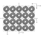
Fig. 1 illustrates the canonical square arrangement of transmitter unit.The layout of emitter coil 11 is illustrated: coil is positioned in the square area of being indicated by setting-out.Size such as the indicated electric power surface that is made of coil of arrow 14 is scheduled to, and can by as vertically indicated this surface of expansion vertically or in the horizontal direction of point 12 and level point 13 be selected.Various similar arrangement are possible, and for example triangular arrangement also is possible.
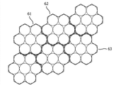
Fig. 2 illustrates the regular hexagon of transmitter unit and arranges.The layout of emitter coil 21 is illustrated; Coil is positioned in as in the indicated hexagonal area 22 of thin dotted line.The size on the electric power surface that is made of coil is scheduled to, and can by as vertically indicated this surface of expansion vertically or in the horizontal direction of point 23 and level point 24 be selected.In this pre-defined rule of similar Fig. 1 and 2 was arranged, the shape of coil can be suitable for this layout separately, and for example square shape is used for arranged in squares and hexagonal shape is used for hexagonal arrangement.But also can use well circular coil, this is so that designing and calculating is simpler.Use the predetermined arrangement of this rule of described coil shape to be well known in the art, for example see US7,576,514.
Point out in addition, US2009/0096413A1 is [0157] section example of having described the Modularized power plate with reference to figure 8.Each rectangular slab is connected to allow a plurality of equipment to be powered in one direction.Yet a string like this plate does not consist of continual extendible electric power surface.In addition, described plate is the unit that separates, and they need central communication and memory cell, and can't autonomous operation.
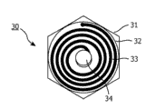
Fig. 3 illustrates the transmitter unit of hexagonal shape.Transmitter unit 30 is shaped according to regular polygon (hexagon 31 among the figure).Transmitter unit comprises emitter coil 33 and can comprise in addition electronic device 34, for example in the control circuit system of the dorsal part of the panel of carrying coil.The zone of coil is by 32 indications of coil border.Circuits System can comprise the electronic device for the electric current of the transducer that has detection and generation or control coil.Thereby electronic device is usually located at the dorsal part of coil 33 and provides flat surfaces for receiver.Transmitter unit has the relevant external shape of type of arranging with coil.Each unit can be arranged in the hexagonal arrangement, but the shape of coil can be round, such as Fig. 3 explanation.
For but the modular system with any extended power surface is provided, each transmitter unit is arranged in the transmitter module.This transmitter module has outer peripheral edges, thereby it is formed and is fitted to the adjacent transmitter module to be used to form the electric power transfer surface, this at least one transmitter unit is arranged in the outer peripheral edges of transmitter module, so that the electric power transfer surface is made of the uninterrupted pattern that adjoins emitter coil of expanding in described surface.For so that each module can be as continuous power surface operation, this transmitter module has for be connected to be used for sharing the interconnecting unit of power supply with the adjacent transmitter module.
Transmitter module can be made of single transmitter unit.But preferably some unit are combined in the module.In this way, control electronic device (for example microprocessor, communication) is shared by each unit, and this has reduced the input for electronic device.The size of module is modularization and drops into trading off between the reduction.
Transmitter module is contemplated into provides between the separate modular the not regular pattern of the gapped emitter coil of tool, i.e. continual pattern.Preferably, as mentioned below, each module is by the input that consists of to reduce more than an emitter coil for module controls.In order to realize seamless zone, the outer peripheral edges of transmitter module must be fitted to the outer peripheral edges of adjacent transmitter module, and transmitter unit is arranged by uninterrupted mode the transmitter module planted agent, and the outer peripheral edges of module should be arranged so that when it is connected with the adjacent transmitter module, in the different transmitter modules two adjoin emitter coil and follow with the coil of this transmitter module and arrange that identical coil arranges, namely adjacent block should between the emitter coil that adjoins also be to be uninterrupted mode.
If the outward flange of transmitter unit is followed the outer peripheral edges pattern of module, the outer peripheral edges of module can be made of the outer peripheral part of transmitter unit.For arranged in squares, modular shape is followed the square shape of unit.The hexagon coil is arranged so that much complicated that modular shape is possible.
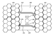
Fig. 4 illustrates the transmitter module 40 based on the hexagon transmitter unit.In example in one of them, transmitter unit 30 is schematically by the line indication of broadening; Each transmitter unit has an emitter coil 46.The first example of transmitter module 41 has 3 hexagon transmitter units.The second example 42 has 4 hexagon transmitter units.The 3rd example 43 has 7 hexagon transmitter units.The 4th example 44 has 6 hexagon transmitter units.Each module has outer peripheral edges 45, and it is schematically indicated by the line of broadening in an exemplary module, and the part of this week cause in each unit of boundary of this module consists of.How following respectively illustrating can make up these modules to form the electric power surface in larger zone.
Fig. 5 illustrates the electric power transfer surface of 3 coil modules.The first transmitter module 51 adjoins the second module 52.The 3rd transmitter module 53 adjoins the second module 52 of complementary orientation equally, then is four module 54.This pattern is extendible arbitrarily in different directions.
Fig. 6 illustrates the electric power surface of 7 coil modules.The first transmitter module 61 adjoins the second module 62.The 3rd module 63 is shown expands this pattern in different directions.
Fig. 7 illustrates the electric power surface of 6 coil modules.The first transmitter module 71 adjoins the second module 72.Other module allows expanding this pattern by the different directions shown in vertical point 73 and the level point 74.
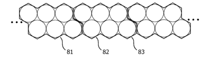
Fig. 8 illustrates the fillet shape electric power surface of 6 coil modules.Module 81,82,83 is used for consisting of fillet shape electric power surface by linear arrangement.
Fig. 9 illustrates the wide bar shaped electric power surface of 6 coil modules.Module 91,92,93 is used for the wide bar shaped electric power surface of layout of constituent ratio Fig. 8 by linear arrangement.
The combination of disparate modules shape also is possible (not shown), as long as they relate to identical coil type of arrangement.
In order to realize not relying on the reasonable electric power transfer of receiver position, the transmitter line loop diameter can be less than receiver coil.Preferably, in any any position, the received device of at least one emitter coil covers fully.
Figure 10 illustrates fixedly layout of machinery.It is fixing that Figure 10 a illustrates embedded (snap-in), and Figure 10 b illustrates dovetail and fixes.The extension 101 that aforesaid transmitter module can make outer peripheral edges be provided with in addition to be arranged in the first peripheral position, 103 is connected all as shown in figure 10 each examples with the complementary notch 102,104 that is used for being positioned at the outer peripheral edges of adjacent transmitter module second week edge position.When this module arrangement was in the electric power transfer surface, primary importance was adjoined the second place of adjacent block.Provide machinery fixing via extension and notch subsequently.
Another task of transmitter module provides the appropriate electrical interconnection between the adjacent block.Need this to connect to be used for connecting supply voltage from module to module.In one embodiment, other signal of communication and other common signal are provided to adjacent module.The details of relevant signal is provided in the back.Interconnecting unit should allow the maximum degree of freedom to come composite module.Preferably they forbid the mistake interconnection, namely avoid unlike signal to be connected to each other.
Various mechanical layouts become obtainable.The preferred mechanical layout of the interconnection between each module is to use contact plug and socket, because this structure typically provides reliable contact.This layout also provides some basic machineries fixing.
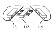
Figure 11 illustrates the mechanical connector layout with horizontal pin.Figure 11 a illustrates the public connector 110 that belongs to transmitter module, and it is used for being connected with the female connectors 111 that belongs to the adjacent transmitter module.Figure 11 b illustrates two female connectors connectors 113,114, and it is used for being connected with the female connectors of adjacent transmitter module via public connectors 112, and this also provides some basic machineries fixing.Pin and socket are pressed horizontal mode and are arranged, so that each module must be stuck in a horizontal plane.
As the advantage of the male-female solution of Figure 11 a indicating, it is Opposite direction connection safety inherently.As the shortcoming of this solution, need two types connector.This has limited the possibility of each module that at random interconnects.Moreover the pin of public connector is expanded at the outward flange of this module.If connector is on the outward flange in electric power transfer zone and be not used, it limits this layout, because this module can't be placed near the edge.
A kind of different solution is shown in Figure 11 b.Herein, this module only comprises female connectors.In order to connect two modules, used the connectors with pin.As advantage, all connectors in this module can be identical types, and this allows the high-freedom degree of module arrangement.Moreover obsolete connector is not expanded at the edge of module.As shortcoming, connector is not Opposite direction connection safety inherently.Must correspondingly select pin to distribute.As minor defect, need additional connectors part.As the advantage of horizontal pin connector, making up highly can be very low.As shortcoming, can not remove or exchange the individual module in the larger zone.In order to realize this point, whole zone must be disassembled.Moreover, the impossible module that some shape is installed.
In one embodiment, in order to allow to install according to random order the module of arbitrary shape, provide the connector with vertical pin.
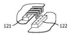
Figure 12 illustrates the example of the mechanical connector layout with vertical pin.Figure 12 a illustrates the layout with public and female connectors.
Figure 12 b illustrates the layout with two vertical female pins and a male connectors.Two kinds of layouts all have and the similar merits and demerits of the relative arrangement with horizontal pin.Another possibility is to use contact spring rather than pin.Subsequently, machinery is fixing must provide the power that each module is kept together.As advantage, described contact does not have can easily install in the expansion of the edge of module and each module significantly.
In transmitter module, when each module arrangement was in the electric power transfer surface, interconnecting unit is as implied above to be configured.This configuration can be: public affairs and female connectors, and it is used for being connected with public connector with the mother of adjacent transmitter module, and public pin is parallel to the electric power surface; Female connectors, it is used for being connected with the female connectors of adjacent transmitter module via the interconnection pin that is parallel to the electric power surface; Public affairs and female connectors, it is used for being connected with public connector with the mother of adjacent transmitter module, and public pin is perpendicular to the electric power surface; Female connectors, it is used for being connected with the female connectors of adjacent transmitter module via the interconnection pin perpendicular to the electric power surface; Perhaps be positioned at each connector of relative position, it has via attachable each contact area of contact spring.
In transmitter module, when each module arrangement was in the electric power transfer surface, interconnecting unit can have following various electrical configuration.In one embodiment, connection is arranged in the second peripheral position along the complementation connection that periphery is arranged in the first peripheral position and adjacent transmitter module, the first and second location matches when each module is arranged by intention, and does not mate the first and second positions when each module is otherwise arranged, thereby be used for providing Opposite direction connection safety.
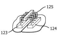
Figure 13 illustrates electrical layout and the location of interconnecting unit.Figure 13 a illustrates the combination that utilizes public connector 131 and female connectors 132.They are Opposite direction connection safety inherently.In addition, connector is placed asymmetrically with respect to the center at the edge of facing of module.As hereinafter illustrated in conjunction with Figure 17, must not face with each other by two connectors not connected to one another.
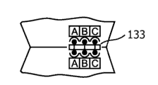
Figure 13 b illustrates the layout with two female connectors and a public connectors 133.It is asymmetric that pin distributes.Therefore need two different pins to distribute.In order to realize Opposite direction connection safety, connector is placed asymmetrically with respect to the center at the edge of facing of module.In this way, similar with situation illustrated in fig. 17, must not face with each other by two connectors not connected to one another.
Figure 14 illustrates by symmetrical pin and distributes the electric connector layout with Opposite direction connection safety.If connector can face in the connector of Rotate 180 ° and rotation be fitted to original connector, then realize correct symmetrical.Distribute the Mirror Symmetry that must have with respect to the centre of connector to realize this point by the pin of A, B, C indication.As shortcoming, all signals (except middle that) must be routed to two pins, this requires larger connector.
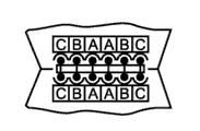
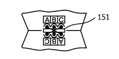
Figure 14 a illustrates the solution with two female connectors and a connectors.Figure 14 b illustrates hybrid solution, and some contacts of one of them connector are male and other is female.Because rotational symmetry, they can combination in any.This hybrid solution usage level pin.In this layout, correct pin faces with each other and any combination of connector allows.Therefore, connector is placed with respect to the Central Symmetry ground at the edge of facing of module.Connector layout is used the connection of arranging along periphery and is had pin with respect to the repetition of center, described center coupling when module arrangement is in the electric power surface.
Figure 15 illustrates the electric connector layout with two female connectors connectors and a public transport fork pin interconnection device.Described connection needs the intersection pin interconnection device 151 between each interconnecting unit.
Another selection that realizes symmetrical connector is to use coaxial connector.Be exemplified as headphone connector (4 or more pin be available) or coaxial power connector.Can use coaxial connection, it is arranged along periphery in the center, described center coupling when each module arrangement is in the electric power surface.Connection in the center perpendicular to electric power surface stacked arrangement also is possible, described center coupling when each module arrangement is in the electric power surface.
In order to allow the flexible arrangement of module, preferably each module has a connector at each edge, and this module may be faced adjacent module at this edge.The type that depends on connector, as explained above it be placed on the center with respect to this edge or depart from the center and place.Not necessarily all these connectors are used in needing in the end to arrange.If used two dissimilar connectors or pin to distribute, then cut apart this module along symmetry axis.Use the connector of the first kind in a side of symmetry axis, use the connector of Second Type in the another side.
Figure 16 illustrates the interconnection of the module with correct orientation.This figure provides the interconnection example of contact position and the interconnection that is used for hexagonal 6 coil modules.Used two types connector.Can flatly draw line of symmetry.This illustrates two kinds and may arrange, namely vertically arranges 161 and horizontal arrangement 162.It also shows for the interconnecting unit 165,166 that connects each module at both direction, and as described belowly be used for the electric power conveying function of this module of control and the controller 167 of other task in each module.
Figure 17 illustrates Opposite direction connection safety.In this example, the vicious interconnection orientation of each module tool.Connect in the trial of two modules in incorrect side, connector 171,172 does not fit each other and incorrect link is avoided.
(not shown) in another embodiment, each module comprise that a central connector and all modules use this connector to connect by flat cable.
Each module can have and keeps adjacent block mechanically to be laid on together device.For example, this can " ratchet " or " embedding " connect shown in Figure 10 a.Fixture can with electric connector combination.It also is possible for example connecting from flat-ribbon cable connector known " sealed ".Exemplary means is the dovetail connection shown in Figure 10 b in addition, and it can use with the electric connector that has as shown in figure 12 vertical pin.The mechanical mutual connected device that for example has the connectors of two dovetails also is possible.Advantageously, it can be fixing to improve machinery with the electric connector combination with horizontal pin.
This system can be provided with the tucker module.This tucker module has at least one outer peripheral edge portion, thereby it is formed and is fitted to the adjacent transmitter module at least one direction and forms the electric power transfer surface.In addition, the outer peripheral edge portion adjacent with each transmitter module is shaped according to the outer peripheral edges of adjacent transmitter module.The tucker module has at least one another periphery, with non-conterminous this another periphery of transmitter module be straight to be used for to the straight border of electric power surface proof.
The tucker module can have the electric function of minimizing or not have electric function.These modules can be used for be filled the gap obtaining the homogeneous area for the interconnection between the local active region, thereby edges of regions is straightened or effectively expand active region.Contingent is that only the surface (such as floor, wall, ceiling etc.) of part will be provided with the wireless power transmission function.So this surperficial remainder does not have air spots capped and that obtain smooth.In order to realize even flat surfaces, can fill " hole " with appropriate " counterfeit " module that does not have electric function.The external shape of each module adapts to the shape of active module embedded therein.In simple case, they have identical shaped.
Figure 18 illustrates the electric power surface, and it has two active regions with 6 coil modules that utilize expansion module 180 to connect.The dynamometer instrument mask has the active region 181,182 that is positioned at same lip-deep two (or more) separation.In one embodiment, in order to connect these zones, the tucker module is inserted between the transmitter module.The tucker module provides the electrical connection between each active region.The tucker module can have the shape identical with transmitter module and connector.If transmitter module does not have straight edge, counterfeit module can be used for the edge in zone is straightened.
In another embodiment, expansion module 180 is provided with for the parts that consist of central control unit.This expansion module has be used to the interconnecting unit 185 that provides power supply to arrive the adjacent transmitter module in addition.Moreover, expansion module can have that the electric power that strides across different transmitter modules for control is carried or the system controller 186 of communication, and/or be used for enabling to control the electric power conveying that strides across different transmitter modules or the operation-interface 188 of communicating by letter, and/or be used for enabling to stride across the data conveying of different transmitter modules or this receiver or the data-interface 187 of communication.Operation-interface can be provided with user interface element, such as button and/or display.
Figure 19 illustrates the bar zone of 6 coil modules and tucker module.Bar shaped electric power surface is made of transmitter module 191.Tucker module 192 is positioned at the external boundary place, and it has straight outer peripheral edges 194.Receiver 193 is shown the adjoining power surface.
Similar with reflector or receiver module, counterfeit module also can comprise soft magnetosphere, and is as mentioned below.In the tucker module, soft magnetosphere can be used for providing the magnetic pull of receiver.This is favourable for edge filling device module, such as Figure 19 explanation.Reflector can still be fixed, even only part is overlapping with emitter coil for it.In this way, can expand like a dream effective active region.
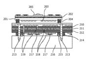
Figure 20 illustrates the cross section of transmitter module and receiver.The vertical structure of this figure explanation this system when receiver is placed on the reflector.Figure mesoscale is not pro rata; Particularly vertically yardstick is increased with respect to horizontal scale.Receiver carrier 201 is formed by the rigid material of for example printed circuit board (PCB) (PCB) material.The receiver winding 203 that represents the receiver coil of receiver places on the side in the face of reflector.It can be made of copper cash, perhaps is made of the structuring copper layer that is laminated to PCB.Permanent magnet 204 is for example by the gluing side that is attached in winding.The soft magnetosphere that permanent magnet is launched device attracts (seeing below), so that receiver is fixed to reflector.In different embodiment, permanent magnet is installed in the center (not shown) of coil.Electronic unit can place on the carrier top, thereby for example the alternating voltage of receiver is carried out rectification.In this embodiment, for example the target device 205 of lamp or light-emitting diode (LED) directly is attached to carrier.Lamp also can utilize the additional mechanical device to be connected to carrier.In this exemplary embodiment, prevent fault thereby receiver contains additional soft magnetosphere 202 to shield alternating magnetic field from electronic circuit, and the space of shielding receiver top is to prevent the excessive emission in magnetic field.
Figure 20 also illustrates the exemplary embodiment of reflector.It comprises diskette 210, tucker and adhesive phase 211 and printed circuit board (PCB) 212.Module can be used fixture (fixation), sept 214 and the seal 215 of similar screw 213 and be fixed to wall 216.Magnetic sheet is made of for example ferritic material, and this material has low-loss when being subject to alternating magnetic field.Owing to being difficult to realize making large thin slice by ferrite, this sheet can be made by single watt that is close together placement.Preferred material is ferrite polymer complex (FPC).FPC is made of the ferrite dust that is blended in the plastic substrate.This material can be easily in large tracts of land, make and can even be designed to and the PCB manufacturing process compatible so that it can be similar to the layer of multi-layer PCB is processed, described in European patent application EP 03101991.2.In order to realize reasonable function, soft magnetosphere thickness is about 1mm or larger.The winding of emitter coil is placed on the magnetic sheet top.Winding can be thin snail winding.Winding can be made or be made by the structuring copper layer that is laminated to diskette by conductive lead wire.Reflector can be by consisting of more than an emitter coil, and described emitter coil is closely placed side by side, as among the figure by shown in the each several part that is positioned at adjacent windings on each side.
Transmitter module comprises controller 217 and other electronic unit that is positioned at as shown in the figure printed circuit board (PCB) 212 dorsal parts.Each parts also can be placed on the side of system or be placed on the diskette rear.Reflector can cover with protective layer.The surface smoothing of reflector is preferably made and advantageously made to this protective layer by the PCB material.This protective layer also can have decoration functions, for example is similar to ceramic tile or Wooden floor tile.The accessory decoration function has optional cover layer.This cover layer can be decoration foil, wallpaper, veneer material, the thin gypsum of thin layer pigment, printing, perhaps such as the floor covering of PCV watt or carpet.Thin level and smooth cover layer even allow magnetic to fix at the emitter coil top.
Example is as being fixed to the additional PCB of soft magnetosphere by lamination, drive electronics can be positioned at the dorsal part of diskette.If necessary, additional PCB can be attached to dorsal part.PCB intercommunicated crossed conductive path 219 and is connected to emitter coil.If necessary, path and diskette insulation (not shown).The electric component that forms driving, control and the telecommunication circuit of reflector is attached on the PCB.For the mechanical pressure on the electronic equipment that prevents dorsal part, added sept 214 so that enough distances to be provided.Sept not only need to be in the position (as shown in the figure) of screw, and can be in excessive layout around the electronic circuit.Optional seal can be avoided environmental impact for the protection of electronic circuit subsequently.
Whole layout can be fixed to wall, ceiling or floor by fixture 213, and this fixture is for example for being used for one or two hole of screw or nail.Fixture can cover so that system is invisible with cover layer after installing.It also can be similar hook and a layout of arranging on the module dorsal part.Should fixing must not expand to the outside of the external shape of module.
For better coupling uniformity is provided, particularly for little receiver, the emitter coil of extra play can be overlapping with ground floor.Overlapping for the flat surfaces of realizing coil in the adjacent block and whole zone, module must have the step shape profile and come overlapping.
In one embodiment, transmitter module has the transmitter unit of ground floor and the transmitter unit of another layer.At least two emitter coils of the overlapping ground floor of emitter coil of another layer, uniform magnetic field arrives receiver to be used for inductive power transfer thereby provide more.Also be possible more than two-layer transmitter unit.In transmitter module, outer peripheral edges also can be provided with the step shape profile, and another layer exceeds ground floor in the expansion of the part place of this periphery.When arranging this transmitter module in the electric power surface, another layer segment of the expansion of a module is assemblied in the complementary extension part below of ground floor.
About providing electric power to emitter coil, each module can have its oneself generator.So thereby each unit also comprises the transmission of electronic switch control this element.Solution is to provide generator for each unit more flexibly.Generator can have two switching devices (for example transistor) that are half-bridge arrangement.As known in the art dawn, the different layout also is possible.Thereby can comprising the auxiliary power transducer, each module provides boost voltage for control circuit.
Supply voltage will be provided to transmitter module, and this supply voltage is the DC power supply normally.Therefore power supply is shared between each module.The relevant pin of connector is connected in parallel.Voltage of power can be provided by center power supply.Provide the supply voltage of separation to be used for electric power transfer and to be used for the control circuit system, this can be favourable.The supply voltage that is used for electric power transfer also can be AC voltage.
In one embodiment, arrange that in transmitter module interconnecting unit is to be used for providing the communication connection between the described adjacent transmitter module.Controller and other electronic unit can be provided for communicate by letter and is used for providing other control signal to arrive adjacent block.Especially, interconnecting unit can be arranged to be used for providing as mentioned above at least two separate power supplies signals.Moreover the signal of telecommunication can be provided for module detection signal, synchronizing signal and/or any other suitable communication or control signal of supply (accommodate) common communicating bus, local communication bus, virtual common communicating bus, connection.
In one embodiment, provide digital communication via communication bus.In the first exemplary embodiment, all modules are shared common communicating bus.Relevant pin at the connector place is connected in parallel and bus is connected to the controller of this module.Preferably, it uses serial data communication.Some standards that existence can be used, for example RS485.Can use the known method of processing anti-collision, for example any delay of reaction.
Optional master controller or remote controller can utilize this bus to control independent module or all public modules.As advantage, each controller of this embodiment only needs a communication port and all modules to interconnect each other.Yet, if a large amount of modules is combined and when communication, communication speed can be low.Moreover there is physical constraints in the common bus system at the number of the module that can be connected, and if module failure and show wrong behavior to bus, whole communication system can be collapsed.
In another embodiment, provide the local communication bus.The local communication bus is the only direct connection between two adjacent blocks.The independent communication line of existence from a controller to each neighbour.Advantageously, it is the connected in series of for example RS232 or has Transistor-Transistor Logic level or lower simple digital circuit.Advantageously, communication speed is high, because not each other impact of module.Mistake during a part connects does not directly affect system's remainder.Although the link between two modules disconnects, whole system can still be communicated by letter.This communication system is for the more robust that can become of the mistake in the communication linkage.Yet, only may communicate with the neighbours that are close to.
In another embodiment, provide virtual common communicating bus.In order to make up high communication speed and global communication, common bus and local bus all are implemented.Local bus can be combined to common communicating bus on request.In the first solution, each module has the device that physically connects all local buss.The behavior of the bus that obtains is similar to described common communicating bus.Change between local bus and the common bus can be relevant with the operational phase.For example in the phase I (seeing below) of debugging (commissioning), bus is in the partial operation pattern, and changes to after this public operation.
In one embodiment, provide the possibility of " broadcasting " order, the operator scheme of this command set bus.Local bus can be ordered with " broadcasting " as common bus.If module or master controller wish with a zone in all module communications, it sent special command before message.If adjacent block receives this order, it will send identical message to the module of all other connections.Module can receive freely different neighbours' identical message for the second time.In this case, message no longer is sent out.In this way, message spreads between whole zone.Thereby local bus is connected to consist of virtual common communicating bus virtually.
In another embodiment, each module has the localized routing table, and this localized routing table can progressively be set up during this transmitter module is with respect to the position of other transmitter module and orientation process determining.When module was wished with another module communication, it sent the message of the identifier that contains this module.The routing table of each module contains the connectivity port that is useful on each message id.If module must be with message communicating to another module, if perhaps module must be forwarded to message another module, it searches the appropriate connectivity port that it must send a message in the routing table.In this way, message is found its path from the source module to the object module.In order to make the communication system robust, each module can be stored the additional replaceable connectivity port for each message id.For the inoperative situation of the communication linkage of preferred connectivity port, this module can select replaceable connectivity port to come route message.
The module detection signal of connection is provided in one embodiment.Each plug can have detection signal, and adjacent block of this detection signal indication is connected to this plug.
In one embodiment, provide the static module detection signal, for example be connected to the digital circuit input of the pin of corresponding connector.As an example, this circuit utilizes pullup resistor to be pulled to high potential.The relevant pin of adjacent connector is connected to ground level (GND).If two modules are connected with these connectors, this circuit is known this connector by drop-down and controller and is connected to adjacent block.It must be symmetrical that pin distributes, so that two modules are known the situation of connection.
In one embodiment, provide the dynamic module detection signal.This circuit is not by short circuit now, and still two circuits relevant with corresponding connector are connected.Each of described two controllers can read the state of this circuit and its level can be set.For example each controller has open-collector output with drop-down this circuit, and during unactivated state, this link tester is crossed pullup resistor and is set to high level.It must be symmetrical that pin distributes, so that two corresponding line are connected.
In one embodiment, for the electric power transfer of synchronously adjacent module, power clock signal is provided as being shared by each module.This signal has the frequency identical with electric power transfer.Power generator is synchronized to this signal.In this way, the phase shift of the alternating magnetic field of each adjacent block can be controlled to keep it constant and or minimize it.If if the larger electric power receiver transmitter unit that need to cover two or more adjacent blocks more than electric power transfer and the electric power receiver of a reflector for example, then this can be necessary.Power clock signal can be provided by center power supply or central primary control device processed.In another embodiment, power clock signal is produced by relevant communication host (master).
In one embodiment, each transmitter module can self-sufficiently operate.In addition, transmitter module comprises that controller with from the master control transmitter unit, for example has the microprocessor of nonvolatile memory.All modules can have the identical layer sub-level, and are arranged to oneself tissue, described in paragraph hereinafter.
The controller of each module can communicate with one another.Each transmitter module can have unique identifier (ID), for example numbers code.ID can be provided by manufacturer.In different examples, between all modules that relate to, consult (negotiate) ID, the order that for example is assembled together by them.ID is stored in the nonvolatile memory.Unit in each module can have serial number, so that each transmitter unit can be addressed separately.Module I D and element number are made up the unique identifier that then provides each independent unit.
In one embodiment, transmitter module comprises the memory for storaging identificating information.Especially, identifying information can comprise when module arrangement is in the electric power surface, is used for the identifying information of identification transmitter module.Moreover identifying information can comprise when module arrangement is in the electric power surface, is used for the transmitter unit addressing information of each transmitter unit of identification.Additionally, identifying information can comprise when module arrangement is in the electric power surface, is used for the type information of identification transmitter module type.Controller is arranged to for carrying identifying information being arranged between the different transmitter modules on electric power surface.
In one embodiment, the controller of transmitter module is arranged to for definite its position and orientation with respect to other module.Use for great majority, know and directly adjoin module and their orientation is enough.More accurately, each module is known the adjacent cells of each own unit.This information can be obtained according to particular request, for example during assembling wireless power zone or and then.This information is stored in nonvolatile memory subsequently.This information determine to be called debugging.Following method is for being used for obtaining the example of debugging.
In one embodiment, determine that manually transmitter module is supplied with respect to position and the orientation of other transmitter module.Has the ID that the special control appliance of user interface can read module.Moreover this control appliance has user interface, and this user interface allows the module virtual group.Before assembling, the user must read the ID of each module.Subsequently each module by be placed on virtually they will be positioned at last the there locational user interface in.At last, control appliance sends to all modules with the positional information of inputting.As advantage, the method does not need local intelligence to be used for determining position and the orientation of transmitter module.Moreover a global communication bus structure is enough to be used in this type of application.Position and orientation that transmitter module manually is set are very flexibly, but it requires the user's of each module of assembling input, and may easily make a mistake.
In one embodiment, determine that during connecting position and orientation information are supplied, namely carry out this at electric power surface assembly process and determine.It requires to be used at least assembling of this control circuit (" hot plug ") at least Static Detection signal of the module that connects and during electric power is connected at each plug (seeing above).If new module is attached to existing zone, it sends its ID by communication channel.Its appended adjacent block of linking is connected in relevant this module of plug registration.Because new module has sent its ID, adjacent block can belong to the signal from this connector correct module I D.In this way, can successfully finish definite.
In one embodiment, utilize transmit a signal to neighbours determine be supplied.Detection line is connected to the controller of module so that the dynamic module detection signal to be provided, as mentioned above from each plug.After the electric power surface-assembled, in response to special event, after for example and then electric power is connected or after the order via the master controller of common communication circuit, begin this deterministic process.Subsequently, each module sends its ID at common communicating bus in succession, simultaneously all detection lines is activated to its connector.Adjacent block can the recognition detection circuit be activated to their connector.They can be associated with this excitation now and send its ID and thereby be their neighbours' module now.
In another embodiment, each connector can belong to independent unit (might allow each unit more than a connector) and module is activated to connector with circuit one by one, and it is numbered via the common communicating bus transmitting element simultaneously.In this way, adjacent block not only can be identified adjacent block, and can identify the definite position of adjacent cells.Similar but in the diverse ways, each connector is relevant with an edge of this module.Subsequently, adjacent block can be determined the orientation of active module.Can derive thus the position of independent unit.
In order to improve reliability, detect each module of neighbours and can use common communicating bus to confirm this detection.The order of module excitation can for example be belonged to the ID numbering of module.Do not have at the appointed time after other module places its ID on the bus, this process finishes (finishing with " overtime ").In different embodiment, before determining, all module registers in this zone are in special " samsara ".So the numbering of module is known and debugging does not need overtime.
After detection process, each module is known its immediate neighbor.Use for great majority, this is enough, but uses for the advanced person, can require each module to know whole view or the wider at least environment of module.Therefore, after first determined samsara, all modules can exchange their information, so that each module obtains complete view information.
As advantage, the method only needs a communication bus, does not have high requirement at the signal line with neighbours simultaneously.
In one embodiment, utilize determining of communicating by letter with neighbours to be supplied.Each connector by the local communication bus provide from/toward the independent digital communication of controller.If two modules are connected, then between two controllers, form exclusive digital communication channel.In deterministic process, each module uses these communication channels to send its ID to its neighbours.In this way, each module obtains the knowledge about its immediate neighbor.Similar with previous embodiment, each connector can be belonged to an edge or be belonged to a unit, so that the orientation that adjacent block can determination module.After detecting immediate neighbor, all modules can exchange their information, so that each module obtains complete view information.For this purpose, additional common communicating bus is used, and perhaps local bus physically or virtually is connected to virtual common communicating bus.As advantage, the method is faster than the sequential grammar that simply transmits a signal to neighbours.Yet as shortcoming, it requires the more communication line of each module.
In one embodiment, the controller of transmitter module is arranged to for search receiner.If receiver is placed on this module, it can be surveyed with any known method.Subsequently, transmitter module and receiver communicate with one another.Except other initialization information, receiver utilizes unique identifier (receiver ID) to come Urine scent.If receiver is verified, module that the controller of transmitter module transmit a request to adjacent (or owning), be detected module that the controller of transmitter module also transmit a request to adjacent (or owning) in other position if having the receiver of same identifier.If module does not detect same receiver in addition, this module controller is taken over the control of electric power transfer.If module detects same receiver in addition, each module must be coordinated the control of electric power transfer.The example of this point is described in following part.
In one embodiment, controller is arranged to for the electric power control between the transmitter unit in the different transmitter modules of coordinating to be arranged in the electric power surface.In order to coordinate electric power control, if detect same receiver more than a module, one of them is assigned to " main control system " related module.Master controller is suitable for sending control signals to other controller in other transmitter module via described interconnecting unit, carries so that control signal is used with the electric power that is used for the module of control under them by described other controller.Have transmitter unit with the optimal communication of receiver (the strongest signal, best signal to noise ratio) based on detection, can realize the selection of main control system.Replacedly first this receiver of discovery can obtain control.This main control system is taken over the control to this receiver.The communicating by letter and the level of power of appropriate unit be set of its management and receiver.If necessary, it can control the unit of adjacent block.For this purpose, it is communicated by letter with adjacent block.Unit and adjacent block in its Request Control adjacent block are made as " being occupied " to the attribute of these unit.Main control system is the level of power of " decision " unit subsequently, and the controller of adjacent block must correspondingly arrange level of power.
Primary module can ask to transfer its function of tonic chord to the neighbours module, and this neighbours' module preferably but do not detect that module of receiver for the unit at it exclusively.May control the situation of the unit that is used for a plurality of receivers for module, this feature is correlated with especially.By this feature, control task can distribute between related module, thereby prevents from making the module excess load with control task.This feature also allows to minimize the production cost of disposal ability and the optimization module of each required module.
In one embodiment, with at least one transmitter unit from be arranged in the electric power surface in different transmitter modules at least one other transmitter unit divide into groups to be supplied.Grouping is finished by main control system.After this grouping, main control system can produce each transmitter unit in control signal to a group subsequently.
In one embodiment, the communication between each module is supplied when relating to more than a transmitter unit in the electric power transfer.Except overlapping receiver, describe such as first forward part, example comprises the electric power transfer that is used for the multiple unit excitation of consulting to be used for larger receiver in addition, the far field compensation is perhaps because the restriction of the electric power transfer that maximum power constraint (when for example needing electric power more than a receiver) causes.
At last, in one embodiment, this system is provided with central location.This central location can be used for following task:
Coordinate, for example reset position is surveyed, and serves as main control system,
Man-machine interface (on/off switch, remote controller),
Managing application data is carried.
Should point out, the present invention can use programmable part and implement in hardware and/or software.To understand, for the sake of clarity above-mentioned specification has been described embodiments of the invention with reference to different parts, functional unit and processor.Yet with obvious, can use between different function units or the processor any proper function to distribute and do not depart from the present invention.For example, being illustrated as the function of being carried out by separative element, processor or controller can be carried out by same processor or controller.Therefore, quote specific functional units and only be counted as the appropriate device that the representation function be used to providing is provided, rather than indicate strict logic OR physical structure or tissue.
Introduced in the present invention a kind of Modular electrical force transmission system that comprises a plurality of transmitter modules.The transmitter module that proposes among the present invention is to use in a kind of system.This system comprises and linking together for transferring electric power inductively to a plurality of transmitter modules of receiver.Preferably, each transmitter module has identical coil layout and outer peripheral edges layout.Each module comprises: at least one transmitter unit, each transmitter unit have an emitter coil, and transmitter unit passes through this emitter coil transferring electric power to receiver; This transmitter module has outer peripheral edges, thereby it is formed and is fitted to the adjacent transmitter module to be used to form the electric power transfer surface, these outer peripheral edges also are formed, so that the electric power transfer surface is made of the uninterrupted pattern that adjoins emitter coil of expanding in described surface; And interconnecting unit (110,111), it is used for being connected to be used for sharing power supply with the adjacent transmitter module.This system has continual coil and arranges.
Although the present invention is described in conjunction with some embodiment, it is not intended to limit in the particular form that provides herein.Additionally, described in conjunction with specific embodiments although feature may look, those skilled in the art will recognize that, the various features of described embodiment can be combined according to the present invention.In the claims, term comprises not getting rid of and has other element or step.
Moreover although list individually, a plurality of devices, element or method step can be implemented by for example individual unit or processor.Additionally, although independent feature may be included in the different claims, these features can be advantageously combined, and to be included in the combination that different claims do not hint feature be not feasible and/or favourable.In addition, feature is included in and does not hint in the claim of a classification and be limited to this classification, and indicative character can be applied to other claim classification equally rightly on the contrary.Moreover the order of feature does not hint that described feature must be by any particular order that be operated in the claim, and the order of the independent step in the claim to a method does not hint that described step must sequentially carry out according to this especially.On the contrary, described step can be carried out according to any proper order.In addition, singular reference is not got rid of a plurality of.Thereby it is a plurality of to mention that " one ", " one ", " first ", " second " etc. do not get rid of.Reference numeral in the claim is provided as illustrative example purely, is not to be read as the scope that limits by any way claim.
Claims (15)
1. transmitter module is used for being connected with other transmitter module to be used for inductively transferring electric power to receiver,
Wherein this transmitter module (40) comprising:
At least one transmitter unit (30), each transmitter unit have an emitter coil (33), and transmitter unit passes through this emitter coil transferring electric power to receiver,
This transmitter module has outer peripheral edges (45), thereby these outer peripheral edges are formed and are fitted to the adjacent transmitter module to be used to form the electric power transfer surface, this at least one transmitter unit is arranged so that this electric power transfer surface is made of the uninterrupted pattern that adjoins emitter coil of expanding in described surface, and
Interconnecting unit (110,111), it is used for being connected to be used for sharing power supply with the adjacent transmitter module.
2. transmitter module as claimed in claim 1, wherein the outer peripheral edges of transmitter module are shaped according to the part of orthohexagonal outer peripheral edges.
3. transmitter module as claimed in claim 1, wherein transmitter module comprises the transmitter unit of ground floor and the transmitter unit of at least one another layer, at least two emitter coils of the emitter coil of this another layer and this ground floor are overlapping.
4. transmitter module as claimed in claim 3, wherein outer peripheral edges also are provided with the step shape profile, and this another layer exceeds this ground floor in the expansion of the part place of these outer peripheral edges.
5. transmitter module as claimed in claim 1, wherein the outer peripheral edges of transmitter module also are provided with the extension (101) that is positioned at the first peripheral position and the complementary notch (102) that is positioned at the second peripheral position, and primary importance is adjoined the second place of adjacent block to be used for providing machinery fixing via extension and notch.
6. transmitter module as claimed in claim 1, wherein interconnecting unit has at least one the configuration that comprises in following:
Public connector (110,111), it is used for being connected with the female connectors of adjacent transmitter module, and public pin is parallel to the electric power surface;
Female connectors (113,114), it is used for being connected with the public connector of adjacent transmitter module, perhaps is used for being connected with the female connectors of adjacent transmitter module via the interconnection pin (112) that is parallel to the electric power surface;
Public connector (121,122), it is used for being connected with the female connectors of adjacent transmitter module, and public pin is perpendicular to the electric power surface;
Female connectors (123,124), it is used for being connected with the public connector of adjacent transmitter module, perhaps is used for being connected with the female connectors of adjacent transmitter module via the interconnection pin (125) perpendicular to the electric power surface;
Connector, it has via the attachable contact area of contact spring.
7. such as claim 1 or 6 described transmitter modules, wherein interconnecting unit has at least one the electrical configuration that comprises in following:
Be arranged in the connection of the first peripheral position and the complementation connection that is positioned at the second peripheral position of adjacent transmitter module along periphery, the first and second location matches when each module is arranged by intention, and does not mate the first and second positions when each module is otherwise arranged, thereby be used for providing Opposite direction connection safety;
Arrange and be the connection of repetition with respect to the center along periphery, when each module arrangement is in the electric power surface, described center and the center coupling that is positioned at the adjacent transmitter module;
Comprise the connection of the intersection pin interconnection device (151) between the interconnecting unit;
Be arranged in the coaxial connection of center along periphery, described center coupling when each module arrangement is in the electric power surface;
Perpendicular to the connection of electric power surface stacked arrangement, mate described center when each module arrangement is in the electric power surface in the center.
8. transmitter module as claimed in claim 1, wherein interconnecting unit is arranged to be used to the communication connection that provides between transmitter module and other transmitter module.
9. transmitter module as claimed in claim 8, wherein interconnecting unit is arranged to for the connection that comprises following at least one:
The power supply signal of at least two separation;
Common communicating bus;
The local communication bus;
Virtual common communicating bus;
The module detection signal that connects;
Synchronizing signal.
10. such as claim 1,8 or 9 described transmitter modules, wherein transmitter module comprises that also this controller (167) is arranged to for following at least one for the controller (167) of control from described transmitter module transferring electric power to receiver:
Coordination is arranged in the electric power control between the transmitter unit in the different transmitter modules in the electric power surface;
Determine this transmitter module with respect to the position that is arranged in other transmitter module in the electric power surface and orientation;
With transmitter unit at least from be arranged in the electric power surface in different transmitter modules at least one other transmitter unit divide into groups;
Search receiner, this receiver stride across the different transmitter modules location that is arranged in the electric power surface.
11. transmitter module as claimed in claim 10, wherein transmitter module comprises for the memory of storing following at least one:
The identifying information that is used for the identification transmitter module;
The transmitter unit addressing information that is used for each transmitter unit of identification;
The type information that is used for identification transmitter module type; And
Its middle controller is arranged to for being arranged at least one of carrying between the different transmitter modules on electric power surface in the above-mentioned information via interconnecting unit.
12. transmitter module as claimed in claim 10, its middle controller (167) are arranged to for determining this transmitter module with respect to the position that is arranged in other transmitter module in the electric power surface and orientation by following at least one:
Via control appliance receiving position and orientation information with user interface;
During the connection of transmitter module, survey at least one control signal of adjacent transmitter module;
Communicate by letter with the master controller of system;
With the adjacent transmitter module communication.
13. the tucker module, it is used for using in the modularization induction power system that limits such as claim 1, and this tucker module (180,192) has:
At least one outer peripheral edge portion, thus it is formed and is fitted to the adjacent transmitter module at least one direction and forms the transferring electric power surface, and the outer peripheral edge portion adjacent with each transmitter module is shaped according to the outer peripheral edges of adjacent transmitter module, and
At least one another periphery (184,194), with non-conterminous this another periphery of transmitter module be straight, to be used for to the straight border of proof, electric power surface.
14. expansion module, it is used for using in the modularization induction power system that limits such as claim 1, this expansion module (180) has at least one outer peripheral edge portion, thereby it is formed and is fitted to adjacent transmitter module formation electric power transfer surface at least one direction, the outer peripheral edge portion adjacent with each transmitter module is shaped according to the outer peripheral edges of adjacent transmitter module, and
Wherein this expansion module comprises:
Interconnecting unit (185), it is used for providing power supply to arrive the adjacent transmitter module, perhaps
System controller (186), it is used for electric power conveying or communication that control strides across different transmitter modules; Perhaps
Operation-interface (188), it is used for enabling to control the electric power that strides across different transmitter modules and carries or communication; Perhaps
Data-interface (187), it is used for enabling to stride across data conveying or the communication of different transmitter modules or receiver.
15. a Modular electrical force transmission system, it comprises and is connected for that inductively transferring electric power is to a plurality of transmitter modules of receiver, and each of wherein said a plurality of transmitter modules comprises:
At least one transmitter unit (30), each transmitter unit have an emitter coil (33), and this transmitter unit passes through this emitter coil transferring electric power to receiver,
This transmitter module has outer peripheral edges (45), thereby it is formed and is fitted to the adjacent transmitter module to be used to form the electric power transfer surface, this at least one transmitter unit is arranged so that the electric power transfer surface is made of the uninterrupted pattern that adjoins emitter coil of expanding in described surface, and
Interconnecting unit (110,111), it is used for being connected to be used for sharing power supply with the adjacent transmitter module.
Applications Claiming Priority (3)
| Application Number | Priority Date | Filing Date | Title |
|---|---|---|---|
| EP10164222 | 2010-05-28 | ||
| EP10164222.1 | 2010-05-28 | ||
| PCT/IB2011/052030 WO2011148289A2 (en) | 2010-05-28 | 2011-05-09 | Transmitter module for use in a modular power transmitting system |
Publications (2)
| Publication Number | Publication Date |
|---|---|
| CN102906832A true CN102906832A (en) | 2013-01-30 |
| CN102906832B CN102906832B (en) | 2017-06-09 |
Family
ID=44626766
Family Applications (1)
| Application Number | Title | Priority Date | Filing Date |
|---|---|---|---|
| CN201180026525.7A Active CN102906832B (en) | 2010-05-28 | 2011-05-09 | For the transmitter module used in Modular electrical force transmission system |
Country Status (5)
| Country | Link |
|---|---|
| US (1) | US9356383B2 (en) |
| EP (1) | EP2577692B1 (en) |
| JP (1) | JP5841132B2 (en) |
| CN (1) | CN102906832B (en) |
| WO (1) | WO2011148289A2 (en) |
Cited By (5)
| Publication number | Priority date | Publication date | Assignee | Title |
|---|---|---|---|---|
| CN103400682A (en) * | 2013-08-14 | 2013-11-20 | 广西电网公司电力科学研究院 | Magnetic core structure and electromagnetic coupling device based on magnetic core structure |
| CN107147221A (en) * | 2017-07-05 | 2017-09-08 | 广东电网有限责任公司电力科学研究院 | The spiral LHM in hexagon concave surface and transmission line of electricity energy transmission system |
| CN107919712A (en) * | 2017-12-26 | 2018-04-17 | 深圳市零壹创新科技有限公司 | A kind of charging module and its a kind of spliced alarm set of application |
| CN109980756A (en) * | 2019-03-25 | 2019-07-05 | 浙江大学 | A kind of device for realizing multi-emitting coil full decoupling in radio energy transmission system |
| CN112309698A (en) * | 2019-07-31 | 2021-02-02 | 沃思电子埃索斯有限责任两合公司 | Coil arrangement and device for wireless electromagnetic transfer of energy |
Families Citing this family (229)
| Publication number | Priority date | Publication date | Assignee | Title |
|---|---|---|---|---|
| US8602833B2 (en) | 2009-08-06 | 2013-12-10 | May Patents Ltd. | Puzzle with conductive path |
| US10146281B2 (en) | 2010-08-31 | 2018-12-04 | Delta Electronics Thailand Public Company Limited | Method and apparatus for load identification |
| US11330714B2 (en) | 2011-08-26 | 2022-05-10 | Sphero, Inc. | Modular electronic building systems with magnetic interconnections and methods of using the same |
| WO2013098647A2 (en) | 2011-12-28 | 2013-07-04 | Delta Electronic (Thailand) Public Company Limited | Resonant bi-directional dc-ac converter |
| CN107275763B (en) | 2012-03-23 | 2020-07-28 | Lg 伊诺特有限公司 | Antenna assembly |
| TWI604480B (en) | 2012-03-23 | 2017-11-01 | Lg伊諾特股份有限公司 | Wireless power receiver and portable terminal comprising the same |
| MX363242B (en) * | 2012-03-28 | 2019-03-14 | Fujitsu Ltd | Wireless power transmission system and wireless power transmission method. |
| CN102638113B (en) * | 2012-04-11 | 2014-08-27 | 华中科技大学 | Magnetic coupling resonance device |
| US9494631B2 (en) | 2012-05-04 | 2016-11-15 | Det International Holding Limited | Intelligent current analysis for resonant converters |
| US9196417B2 (en) | 2012-05-04 | 2015-11-24 | Det International Holding Limited | Magnetic configuration for high efficiency power processing |
| US10553351B2 (en) * | 2012-05-04 | 2020-02-04 | Delta Electronics (Thailand) Public Co., Ltd. | Multiple cells magnetic structure for wireless power |
| EP3264564A1 (en) | 2012-05-04 | 2018-01-03 | DET International Holding Limited | Multiple resonant cells for inductive charging pads |
| US20130314188A1 (en) | 2012-05-04 | 2013-11-28 | Ionel Jitaru | Magnetic Structure for Large Air Gap |
| US9838083B2 (en) | 2014-07-21 | 2017-12-05 | Energous Corporation | Systems and methods for communication with remote management systems |
| US9124125B2 (en) | 2013-05-10 | 2015-09-01 | Energous Corporation | Wireless power transmission with selective range |
| US9923386B1 (en) | 2012-07-06 | 2018-03-20 | Energous Corporation | Systems and methods for wireless power transmission by modifying a number of antenna elements used to transmit power waves to a receiver |
| US10199835B2 (en) | 2015-12-29 | 2019-02-05 | Energous Corporation | Radar motion detection using stepped frequency in wireless power transmission system |
| US9882427B2 (en) | 2013-05-10 | 2018-01-30 | Energous Corporation | Wireless power delivery using a base station to control operations of a plurality of wireless power transmitters |
| US10050462B1 (en) | 2013-08-06 | 2018-08-14 | Energous Corporation | Social power sharing for mobile devices based on pocket-forming |
| US9882430B1 (en) | 2014-05-07 | 2018-01-30 | Energous Corporation | Cluster management of transmitters in a wireless power transmission system |
| US10381880B2 (en) | 2014-07-21 | 2019-08-13 | Energous Corporation | Integrated antenna structure arrays for wireless power transmission |
| US10211674B1 (en) | 2013-06-12 | 2019-02-19 | Energous Corporation | Wireless charging using selected reflectors |
| US9843201B1 (en) | 2012-07-06 | 2017-12-12 | Energous Corporation | Wireless power transmitter that selects antenna sets for transmitting wireless power to a receiver based on location of the receiver, and methods of use thereof |
| US10141768B2 (en) | 2013-06-03 | 2018-11-27 | Energous Corporation | Systems and methods for maximizing wireless power transfer efficiency by instructing a user to change a receiver device's position |
| US9859757B1 (en) | 2013-07-25 | 2018-01-02 | Energous Corporation | Antenna tile arrangements in electronic device enclosures |
| US11502551B2 (en) | 2012-07-06 | 2022-11-15 | Energous Corporation | Wirelessly charging multiple wireless-power receivers using different subsets of an antenna array to focus energy at different locations |
| US10291066B1 (en) | 2014-05-07 | 2019-05-14 | Energous Corporation | Power transmission control systems and methods |
| US9973021B2 (en) | 2012-07-06 | 2018-05-15 | Energous Corporation | Receivers for wireless power transmission |
| US9847679B2 (en) | 2014-05-07 | 2017-12-19 | Energous Corporation | System and method for controlling communication between wireless power transmitter managers |
| US9893555B1 (en) | 2013-10-10 | 2018-02-13 | Energous Corporation | Wireless charging of tools using a toolbox transmitter |
| US10263432B1 (en) | 2013-06-25 | 2019-04-16 | Energous Corporation | Multi-mode transmitter with an antenna array for delivering wireless power and providing Wi-Fi access |
| US9853458B1 (en) | 2014-05-07 | 2017-12-26 | Energous Corporation | Systems and methods for device and power receiver pairing |
| US10199849B1 (en) | 2014-08-21 | 2019-02-05 | Energous Corporation | Method for automatically testing the operational status of a wireless power receiver in a wireless power transmission system |
| US9941707B1 (en) | 2013-07-19 | 2018-04-10 | Energous Corporation | Home base station for multiple room coverage with multiple transmitters |
| US10211680B2 (en) | 2013-07-19 | 2019-02-19 | Energous Corporation | Method for 3 dimensional pocket-forming |
| US9893768B2 (en) | 2012-07-06 | 2018-02-13 | Energous Corporation | Methodology for multiple pocket-forming |
| US10312715B2 (en) | 2015-09-16 | 2019-06-04 | Energous Corporation | Systems and methods for wireless power charging |
| US9887584B1 (en) | 2014-08-21 | 2018-02-06 | Energous Corporation | Systems and methods for a configuration web service to provide configuration of a wireless power transmitter within a wireless power transmission system |
| US10128693B2 (en) | 2014-07-14 | 2018-11-13 | Energous Corporation | System and method for providing health safety in a wireless power transmission system |
| US9843213B2 (en) | 2013-08-06 | 2017-12-12 | Energous Corporation | Social power sharing for mobile devices based on pocket-forming |
| US20140008993A1 (en) | 2012-07-06 | 2014-01-09 | DvineWave Inc. | Methodology for pocket-forming |
| US9941747B2 (en) | 2014-07-14 | 2018-04-10 | Energous Corporation | System and method for manually selecting and deselecting devices to charge in a wireless power network |
| US10206185B2 (en) | 2013-05-10 | 2019-02-12 | Energous Corporation | System and methods for wireless power transmission to an electronic device in accordance with user-defined restrictions |
| US10090886B1 (en) | 2014-07-14 | 2018-10-02 | Energous Corporation | System and method for enabling automatic charging schedules in a wireless power network to one or more devices |
| US9941754B2 (en) | 2012-07-06 | 2018-04-10 | Energous Corporation | Wireless power transmission with selective range |
| US10224758B2 (en) | 2013-05-10 | 2019-03-05 | Energous Corporation | Wireless powering of electronic devices with selective delivery range |
| US9906065B2 (en) | 2012-07-06 | 2018-02-27 | Energous Corporation | Systems and methods of transmitting power transmission waves based on signals received at first and second subsets of a transmitter's antenna array |
| US10124754B1 (en) | 2013-07-19 | 2018-11-13 | Energous Corporation | Wireless charging and powering of electronic sensors in a vehicle |
| US10992187B2 (en) | 2012-07-06 | 2021-04-27 | Energous Corporation | System and methods of using electromagnetic waves to wirelessly deliver power to electronic devices |
| US10439448B2 (en) | 2014-08-21 | 2019-10-08 | Energous Corporation | Systems and methods for automatically testing the communication between wireless power transmitter and wireless power receiver |
| US9252628B2 (en) | 2013-05-10 | 2016-02-02 | Energous Corporation | Laptop computer as a transmitter for wireless charging |
| US9438045B1 (en) | 2013-05-10 | 2016-09-06 | Energous Corporation | Methods and systems for maximum power point transfer in receivers |
| US9966765B1 (en) | 2013-06-25 | 2018-05-08 | Energous Corporation | Multi-mode transmitter |
| US20150326070A1 (en) | 2014-05-07 | 2015-11-12 | Energous Corporation | Methods and Systems for Maximum Power Point Transfer in Receivers |
| US9871398B1 (en) | 2013-07-01 | 2018-01-16 | Energous Corporation | Hybrid charging method for wireless power transmission based on pocket-forming |
| US10965164B2 (en) | 2012-07-06 | 2021-03-30 | Energous Corporation | Systems and methods of wirelessly delivering power to a receiver device |
| US10141791B2 (en) | 2014-05-07 | 2018-11-27 | Energous Corporation | Systems and methods for controlling communications during wireless transmission of power using application programming interfaces |
| US9859797B1 (en) | 2014-05-07 | 2018-01-02 | Energous Corporation | Synchronous rectifier design for wireless power receiver |
| US10075008B1 (en) | 2014-07-14 | 2018-09-11 | Energous Corporation | Systems and methods for manually adjusting when receiving electronic devices are scheduled to receive wirelessly delivered power from a wireless power transmitter in a wireless power network |
| US9899861B1 (en) | 2013-10-10 | 2018-02-20 | Energous Corporation | Wireless charging methods and systems for game controllers, based on pocket-forming |
| US10193396B1 (en) | 2014-05-07 | 2019-01-29 | Energous Corporation | Cluster management of transmitters in a wireless power transmission system |
| US10218227B2 (en) | 2014-05-07 | 2019-02-26 | Energous Corporation | Compact PIFA antenna |
| US9853692B1 (en) | 2014-05-23 | 2017-12-26 | Energous Corporation | Systems and methods for wireless power transmission |
| US9893554B2 (en) | 2014-07-14 | 2018-02-13 | Energous Corporation | System and method for providing health safety in a wireless power transmission system |
| US10128699B2 (en) | 2014-07-14 | 2018-11-13 | Energous Corporation | Systems and methods of providing wireless power using receiver device sensor inputs |
| US9847677B1 (en) | 2013-10-10 | 2017-12-19 | Energous Corporation | Wireless charging and powering of healthcare gadgets and sensors |
| US10008889B2 (en) | 2014-08-21 | 2018-06-26 | Energous Corporation | Method for automatically testing the operational status of a wireless power receiver in a wireless power transmission system |
| US10148097B1 (en) | 2013-11-08 | 2018-12-04 | Energous Corporation | Systems and methods for using a predetermined number of communication channels of a wireless power transmitter to communicate with different wireless power receivers |
| US10992185B2 (en) | 2012-07-06 | 2021-04-27 | Energous Corporation | Systems and methods of using electromagnetic waves to wirelessly deliver power to game controllers |
| US9859756B2 (en) | 2012-07-06 | 2018-01-02 | Energous Corporation | Transmittersand methods for adjusting wireless power transmission based on information from receivers |
| US9900057B2 (en) | 2012-07-06 | 2018-02-20 | Energous Corporation | Systems and methods for assigning groups of antenas of a wireless power transmitter to different wireless power receivers, and determining effective phases to use for wirelessly transmitting power using the assigned groups of antennas |
| US9954374B1 (en) | 2014-05-23 | 2018-04-24 | Energous Corporation | System and method for self-system analysis for detecting a fault in a wireless power transmission Network |
| US10223717B1 (en) | 2014-05-23 | 2019-03-05 | Energous Corporation | Systems and methods for payment-based authorization of wireless power transmission service |
| US9787103B1 (en) | 2013-08-06 | 2017-10-10 | Energous Corporation | Systems and methods for wirelessly delivering power to electronic devices that are unable to communicate with a transmitter |
| US10063106B2 (en) | 2014-05-23 | 2018-08-28 | Energous Corporation | System and method for a self-system analysis in a wireless power transmission network |
| US10063105B2 (en) | 2013-07-11 | 2018-08-28 | Energous Corporation | Proximity transmitters for wireless power charging systems |
| US9831718B2 (en) | 2013-07-25 | 2017-11-28 | Energous Corporation | TV with integrated wireless power transmitter |
| US9891669B2 (en) | 2014-08-21 | 2018-02-13 | Energous Corporation | Systems and methods for a configuration web service to provide configuration of a wireless power transmitter within a wireless power transmission system |
| US10243414B1 (en) | 2014-05-07 | 2019-03-26 | Energous Corporation | Wearable device with wireless power and payload receiver |
| US9887739B2 (en) | 2012-07-06 | 2018-02-06 | Energous Corporation | Systems and methods for wireless power transmission by comparing voltage levels associated with power waves transmitted by antennas of a plurality of antennas of a transmitter to determine appropriate phase adjustments for the power waves |
| US9867062B1 (en) | 2014-07-21 | 2018-01-09 | Energous Corporation | System and methods for using a remote server to authorize a receiving device that has requested wireless power and to determine whether another receiving device should request wireless power in a wireless power transmission system |
| US9899873B2 (en) * | 2014-05-23 | 2018-02-20 | Energous Corporation | System and method for generating a power receiver identifier in a wireless power network |
| US10205239B1 (en) | 2014-05-07 | 2019-02-12 | Energous Corporation | Compact PIFA antenna |
| US9991741B1 (en) | 2014-07-14 | 2018-06-05 | Energous Corporation | System for tracking and reporting status and usage information in a wireless power management system |
| US9368020B1 (en) | 2013-05-10 | 2016-06-14 | Energous Corporation | Off-premises alert system and method for wireless power receivers in a wireless power network |
| US9143000B2 (en) | 2012-07-06 | 2015-09-22 | Energous Corporation | Portable wireless charging pad |
| US9793758B2 (en) | 2014-05-23 | 2017-10-17 | Energous Corporation | Enhanced transmitter using frequency control for wireless power transmission |
| US9825674B1 (en) | 2014-05-23 | 2017-11-21 | Energous Corporation | Enhanced transmitter that selects configurations of antenna elements for performing wireless power transmission and receiving functions |
| US9876394B1 (en) | 2014-05-07 | 2018-01-23 | Energous Corporation | Boost-charger-boost system for enhanced power delivery |
| US9948135B2 (en) | 2015-09-22 | 2018-04-17 | Energous Corporation | Systems and methods for identifying sensitive objects in a wireless charging transmission field |
| US10063064B1 (en) * | 2014-05-23 | 2018-08-28 | Energous Corporation | System and method for generating a power receiver identifier in a wireless power network |
| US10230266B1 (en) | 2014-02-06 | 2019-03-12 | Energous Corporation | Wireless power receivers that communicate status data indicating wireless power transmission effectiveness with a transmitter using a built-in communications component of a mobile device, and methods of use thereof |
| US10224982B1 (en) | 2013-07-11 | 2019-03-05 | Energous Corporation | Wireless power transmitters for transmitting wireless power and tracking whether wireless power receivers are within authorized locations |
| US10211682B2 (en) | 2014-05-07 | 2019-02-19 | Energous Corporation | Systems and methods for controlling operation of a transmitter of a wireless power network based on user instructions received from an authenticated computing device powered or charged by a receiver of the wireless power network |
| US9876648B2 (en) | 2014-08-21 | 2018-01-23 | Energous Corporation | System and method to control a wireless power transmission system by configuration of wireless power transmission control parameters |
| US9806564B2 (en) | 2014-05-07 | 2017-10-31 | Energous Corporation | Integrated rectifier and boost converter for wireless power transmission |
| US10103582B2 (en) | 2012-07-06 | 2018-10-16 | Energous Corporation | Transmitters for wireless power transmission |
| US10090699B1 (en) | 2013-11-01 | 2018-10-02 | Energous Corporation | Wireless powered house |
| US9912199B2 (en) | 2012-07-06 | 2018-03-06 | Energous Corporation | Receivers for wireless power transmission |
| US10038337B1 (en) | 2013-09-16 | 2018-07-31 | Energous Corporation | Wireless power supply for rescue devices |
| US10256657B2 (en) | 2015-12-24 | 2019-04-09 | Energous Corporation | Antenna having coaxial structure for near field wireless power charging |
| US10291055B1 (en) | 2014-12-29 | 2019-05-14 | Energous Corporation | Systems and methods for controlling far-field wireless power transmission based on battery power levels of a receiving device |
| US9812890B1 (en) | 2013-07-11 | 2017-11-07 | Energous Corporation | Portable wireless charging pad |
| US9939864B1 (en) | 2014-08-21 | 2018-04-10 | Energous Corporation | System and method to control a wireless power transmission system by configuration of wireless power transmission control parameters |
| US10186913B2 (en) | 2012-07-06 | 2019-01-22 | Energous Corporation | System and methods for pocket-forming based on constructive and destructive interferences to power one or more wireless power receivers using a wireless power transmitter including a plurality of antennas |
| US9824815B2 (en) | 2013-05-10 | 2017-11-21 | Energous Corporation | Wireless charging and powering of healthcare gadgets and sensors |
| US9876379B1 (en) | 2013-07-11 | 2018-01-23 | Energous Corporation | Wireless charging and powering of electronic devices in a vehicle |
| US10270261B2 (en) | 2015-09-16 | 2019-04-23 | Energous Corporation | Systems and methods of object detection in wireless power charging systems |
| US9666357B2 (en) | 2012-09-11 | 2017-05-30 | Qualcomm Incorporated | Apparatus system, and method for wirelessly receiving power using conductive structures |
| US20140103731A1 (en) * | 2012-10-12 | 2014-04-17 | Panasonic Corporation | Contactless power supply system and power reception device |
| US10605464B2 (en) | 2012-10-15 | 2020-03-31 | Whirlpool Corporation | Induction cooktop |
| ITTO20120896A1 (en) | 2012-10-15 | 2014-04-16 | Indesit Co Spa | INDUCTION HOB |
| GB2512855A (en) | 2013-04-09 | 2014-10-15 | Bombardier Transp Gmbh | Receiving device for receiving a magnetic field and for producing electric energy by magnetic induction |
| GB2512862A (en) | 2013-04-09 | 2014-10-15 | Bombardier Transp Gmbh | Receiving device with coil of electric line for receiving a magnetic field and for producing electric energy by magnetic induction |
| GB2512859A (en) * | 2013-04-09 | 2014-10-15 | Bombardier Transp Gmbh | Structure of a receiving device for receiving a magnetic field and for producing electric energy by magnetic induction |
| US9866279B2 (en) | 2013-05-10 | 2018-01-09 | Energous Corporation | Systems and methods for selecting which power transmitter should deliver wireless power to a receiving device in a wireless power delivery network |
| US9538382B2 (en) | 2013-05-10 | 2017-01-03 | Energous Corporation | System and method for smart registration of wireless power receivers in a wireless power network |
| US9419443B2 (en) | 2013-05-10 | 2016-08-16 | Energous Corporation | Transducer sound arrangement for pocket-forming |
| US9537357B2 (en) | 2013-05-10 | 2017-01-03 | Energous Corporation | Wireless sound charging methods and systems for game controllers, based on pocket-forming |
| US9819230B2 (en) | 2014-05-07 | 2017-11-14 | Energous Corporation | Enhanced receiver for wireless power transmission |
| US10103552B1 (en) | 2013-06-03 | 2018-10-16 | Energous Corporation | Protocols for authenticated wireless power transmission |
| US10003211B1 (en) | 2013-06-17 | 2018-06-19 | Energous Corporation | Battery life of portable electronic devices |
| KR101950947B1 (en) * | 2013-06-27 | 2019-02-21 | 엘지이노텍 주식회사 | Receiving antennas and wireless power receiving apparatus comprising the same |
| US10021523B2 (en) | 2013-07-11 | 2018-07-10 | Energous Corporation | Proximity transmitters for wireless power charging systems |
| US9979440B1 (en) | 2013-07-25 | 2018-05-22 | Energous Corporation | Antenna tile arrangements configured to operate as one functional unit |
| US20150115881A1 (en) * | 2013-10-25 | 2015-04-30 | Samsung Electro-Mechanics Co., Ltd. | Wireless power transceiver and portable terminal having the same |
| US10110075B2 (en) * | 2013-11-14 | 2018-10-23 | Powermat Technologies Ltd. | System and method for selecting power transmitters across a wireless power coupling |
| US9935482B1 (en) | 2014-02-06 | 2018-04-03 | Energous Corporation | Wireless power transmitters that transmit at determined times based on power availability and consumption at a receiving mobile device |
| US10075017B2 (en) | 2014-02-06 | 2018-09-11 | Energous Corporation | External or internal wireless power receiver with spaced-apart antenna elements for charging or powering mobile devices using wirelessly delivered power |
| KR101762778B1 (en) | 2014-03-04 | 2017-07-28 | 엘지이노텍 주식회사 | Wireless communication and charge substrate and wireless communication and charge device |
| US10158257B2 (en) | 2014-05-01 | 2018-12-18 | Energous Corporation | System and methods for using sound waves to wirelessly deliver power to electronic devices |
| US9966784B2 (en) | 2014-06-03 | 2018-05-08 | Energous Corporation | Systems and methods for extending battery life of portable electronic devices charged by sound |
| US9973008B1 (en) | 2014-05-07 | 2018-05-15 | Energous Corporation | Wireless power receiver with boost converters directly coupled to a storage element |
| US9800172B1 (en) | 2014-05-07 | 2017-10-24 | Energous Corporation | Integrated rectifier and boost converter for boosting voltage received from wireless power transmission waves |
| US10153653B1 (en) | 2014-05-07 | 2018-12-11 | Energous Corporation | Systems and methods for using application programming interfaces to control communications between a transmitter and a receiver |
| US10170917B1 (en) | 2014-05-07 | 2019-01-01 | Energous Corporation | Systems and methods for managing and controlling a wireless power network by establishing time intervals during which receivers communicate with a transmitter |
| US10153645B1 (en) | 2014-05-07 | 2018-12-11 | Energous Corporation | Systems and methods for designating a master power transmitter in a cluster of wireless power transmitters |
| US9876536B1 (en) | 2014-05-23 | 2018-01-23 | Energous Corporation | Systems and methods for assigning groups of antennas to transmit wireless power to different wireless power receivers |
| WO2016005984A1 (en) * | 2014-07-10 | 2016-01-14 | Powermat Technologies Ltd. | System and methods for power coupling using coils array |
| US10068703B1 (en) | 2014-07-21 | 2018-09-04 | Energous Corporation | Integrated miniature PIFA with artificial magnetic conductor metamaterials |
| US9871301B2 (en) | 2014-07-21 | 2018-01-16 | Energous Corporation | Integrated miniature PIFA with artificial magnetic conductor metamaterials |
| US10116143B1 (en) | 2014-07-21 | 2018-10-30 | Energous Corporation | Integrated antenna arrays for wireless power transmission |
| KR102479354B1 (en) * | 2014-08-12 | 2022-12-19 | 애플 인크. | System and method for power transfer |
| US9917477B1 (en) | 2014-08-21 | 2018-03-13 | Energous Corporation | Systems and methods for automatically testing the communication between power transmitter and wireless receiver |
| US9965009B1 (en) | 2014-08-21 | 2018-05-08 | Energous Corporation | Systems and methods for assigning a power receiver to individual power transmitters based on location of the power receiver |
| BR112017007360A2 (en) * | 2014-10-10 | 2017-12-19 | Formica Corp | decorative multilayer surface finish materials having embedded conductive materials, solid surfaces made therewith, methods for making and using these surface materials |
| US10122415B2 (en) | 2014-12-27 | 2018-11-06 | Energous Corporation | Systems and methods for assigning a set of antennas of a wireless power transmitter to a wireless power receiver based on a location of the wireless power receiver |
| US10027147B2 (en) | 2015-01-23 | 2018-07-17 | Qualcomm Incorporated | Methods and apparatus for a modular coil holder for an extended wireless charging roadway assembly |
| US9893535B2 (en) | 2015-02-13 | 2018-02-13 | Energous Corporation | Systems and methods for determining optimal charging positions to maximize efficiency of power received from wirelessly delivered sound wave energy |
| US10111590B2 (en) | 2015-08-26 | 2018-10-30 | Nxp B.V. | Health monitoring device |
| US10523033B2 (en) | 2015-09-15 | 2019-12-31 | Energous Corporation | Receiver devices configured to determine location within a transmission field |
| US9906275B2 (en) | 2015-09-15 | 2018-02-27 | Energous Corporation | Identifying receivers in a wireless charging transmission field |
| US9893538B1 (en) | 2015-09-16 | 2018-02-13 | Energous Corporation | Systems and methods of object detection in wireless power charging systems |
| US10778041B2 (en) | 2015-09-16 | 2020-09-15 | Energous Corporation | Systems and methods for generating power waves in a wireless power transmission system |
| US10158259B1 (en) | 2015-09-16 | 2018-12-18 | Energous Corporation | Systems and methods for identifying receivers in a transmission field by transmitting exploratory power waves towards different segments of a transmission field |
| US10008875B1 (en) | 2015-09-16 | 2018-06-26 | Energous Corporation | Wireless power transmitter configured to transmit power waves to a predicted location of a moving wireless power receiver |
| US10199850B2 (en) | 2015-09-16 | 2019-02-05 | Energous Corporation | Systems and methods for wirelessly transmitting power from a transmitter to a receiver by determining refined locations of the receiver in a segmented transmission field associated with the transmitter |
| US11710321B2 (en) | 2015-09-16 | 2023-07-25 | Energous Corporation | Systems and methods of object detection in wireless power charging systems |
| US9941752B2 (en) | 2015-09-16 | 2018-04-10 | Energous Corporation | Systems and methods of object detection in wireless power charging systems |
| US10186893B2 (en) | 2015-09-16 | 2019-01-22 | Energous Corporation | Systems and methods for real time or near real time wireless communications between a wireless power transmitter and a wireless power receiver |
| US10211685B2 (en) | 2015-09-16 | 2019-02-19 | Energous Corporation | Systems and methods for real or near real time wireless communications between a wireless power transmitter and a wireless power receiver |
| US9871387B1 (en) | 2015-09-16 | 2018-01-16 | Energous Corporation | Systems and methods of object detection using one or more video cameras in wireless power charging systems |
| US10153660B1 (en) | 2015-09-22 | 2018-12-11 | Energous Corporation | Systems and methods for preconfiguring sensor data for wireless charging systems |
| US10128686B1 (en) | 2015-09-22 | 2018-11-13 | Energous Corporation | Systems and methods for identifying receiver locations using sensor technologies |
| US10135294B1 (en) | 2015-09-22 | 2018-11-20 | Energous Corporation | Systems and methods for preconfiguring transmission devices for power wave transmissions based on location data of one or more receivers |
| US10135295B2 (en) | 2015-09-22 | 2018-11-20 | Energous Corporation | Systems and methods for nullifying energy levels for wireless power transmission waves |
| US10050470B1 (en) | 2015-09-22 | 2018-08-14 | Energous Corporation | Wireless power transmission device having antennas oriented in three dimensions |
| US10033222B1 (en) | 2015-09-22 | 2018-07-24 | Energous Corporation | Systems and methods for determining and generating a waveform for wireless power transmission waves |
| US10027168B2 (en) | 2015-09-22 | 2018-07-17 | Energous Corporation | Systems and methods for generating and transmitting wireless power transmission waves using antennas having a spacing that is selected by the transmitter |
| US10020678B1 (en) | 2015-09-22 | 2018-07-10 | Energous Corporation | Systems and methods for selecting antennas to generate and transmit power transmission waves |
| US10734717B2 (en) | 2015-10-13 | 2020-08-04 | Energous Corporation | 3D ceramic mold antenna |
| US10333332B1 (en) | 2015-10-13 | 2019-06-25 | Energous Corporation | Cross-polarized dipole antenna |
| US9899744B1 (en) | 2015-10-28 | 2018-02-20 | Energous Corporation | Antenna for wireless charging systems |
| US9853485B2 (en) | 2015-10-28 | 2017-12-26 | Energous Corporation | Antenna for wireless charging systems |
| US10027180B1 (en) | 2015-11-02 | 2018-07-17 | Energous Corporation | 3D triple linear antenna that acts as heat sink |
| US10063108B1 (en) | 2015-11-02 | 2018-08-28 | Energous Corporation | Stamped three-dimensional antenna |
| US10135112B1 (en) | 2015-11-02 | 2018-11-20 | Energous Corporation | 3D antenna mount |
| US10320446B2 (en) | 2015-12-24 | 2019-06-11 | Energous Corporation | Miniaturized highly-efficient designs for near-field power transfer system |
| US10027159B2 (en) | 2015-12-24 | 2018-07-17 | Energous Corporation | Antenna for transmitting wireless power signals |
| US10116162B2 (en) | 2015-12-24 | 2018-10-30 | Energous Corporation | Near field transmitters with harmonic filters for wireless power charging |
| US10038332B1 (en) | 2015-12-24 | 2018-07-31 | Energous Corporation | Systems and methods of wireless power charging through multiple receiving devices |
| US11863001B2 (en) | 2015-12-24 | 2024-01-02 | Energous Corporation | Near-field antenna for wireless power transmission with antenna elements that follow meandering patterns |
| US10079515B2 (en) | 2016-12-12 | 2018-09-18 | Energous Corporation | Near-field RF charging pad with multi-band antenna element with adaptive loading to efficiently charge an electronic device at any position on the pad |
| US10256677B2 (en) | 2016-12-12 | 2019-04-09 | Energous Corporation | Near-field RF charging pad with adaptive loading to efficiently charge an electronic device at any position on the pad |
| US10263476B2 (en) | 2015-12-29 | 2019-04-16 | Energous Corporation | Transmitter board allowing for modular antenna configurations in wireless power transmission systems |
| DE102016218026A1 (en) | 2016-09-20 | 2018-03-22 | Laird Dabendorf Gmbh | Device and method for generating an electromagnetic field for inductive energy transmission |
| CN107872098A (en) * | 2016-09-23 | 2018-04-03 | 苹果公司 | The interconnection of multilayer emitter coil arrangement in wireless charging electrical pad |
| US20180090999A1 (en) * | 2016-09-23 | 2018-03-29 | Apple Inc. | Wireless charging mat with multiple coil arrangements optimized for different devices |
| US10923954B2 (en) | 2016-11-03 | 2021-02-16 | Energous Corporation | Wireless power receiver with a synchronous rectifier |
| JP6691273B2 (en) | 2016-12-12 | 2020-04-28 | エナージャス コーポレイション | A method for selectively activating the antenna area of a near-field charging pad to maximize delivered wireless power |
| US10389161B2 (en) | 2017-03-15 | 2019-08-20 | Energous Corporation | Surface mount dielectric antennas for wireless power transmitters |
| US10680319B2 (en) | 2017-01-06 | 2020-06-09 | Energous Corporation | Devices and methods for reducing mutual coupling effects in wireless power transmission systems |
| US10439442B2 (en) | 2017-01-24 | 2019-10-08 | Energous Corporation | Microstrip antennas for wireless power transmitters |
| EP3593406B1 (en) * | 2017-03-06 | 2023-11-01 | Suffuse Inc. | Interactive digital platform device and method |
| WO2018183892A1 (en) | 2017-03-30 | 2018-10-04 | Energous Corporation | Flat antennas having two or more resonant frequencies for use in wireless power transmission systems |
| US10511097B2 (en) | 2017-05-12 | 2019-12-17 | Energous Corporation | Near-field antennas for accumulating energy at a near-field distance with minimal far-field gain |
| US11462949B2 (en) | 2017-05-16 | 2022-10-04 | Wireless electrical Grid LAN, WiGL Inc | Wireless charging method and system |
| US10848853B2 (en) | 2017-06-23 | 2020-11-24 | Energous Corporation | Systems, methods, and devices for utilizing a wire of a sound-producing device as an antenna for receipt of wirelessly delivered power |
| EP3432682A1 (en) | 2017-07-18 | 2019-01-23 | Whirlpool Corporation | Method for operating an induction cooking hob and cooking hob using such method |
| US10122219B1 (en) | 2017-10-10 | 2018-11-06 | Energous Corporation | Systems, methods, and devices for using a battery as a antenna for receiving wirelessly delivered power from radio frequency power waves |
| US10993292B2 (en) | 2017-10-23 | 2021-04-27 | Whirlpool Corporation | System and method for tuning an induction circuit |
| US11342798B2 (en) | 2017-10-30 | 2022-05-24 | Energous Corporation | Systems and methods for managing coexistence of wireless-power signals and data signals operating in a same frequency band |
| US20190190193A1 (en) * | 2017-12-18 | 2019-06-20 | Littlebits Electronics Inc. | Modular electronic building systems and methods of using the same |
| US10615647B2 (en) | 2018-02-02 | 2020-04-07 | Energous Corporation | Systems and methods for detecting wireless power receivers and other objects at a near-field charging pad |
| US11159057B2 (en) | 2018-03-14 | 2021-10-26 | Energous Corporation | Loop antennas with selectively-activated feeds to control propagation patterns of wireless power signals |
| EP3544377B1 (en) | 2018-03-23 | 2020-08-05 | Whirlpool Corporation | Temperature sensor compression features for induction cooktop assembly |
| EP3544376B1 (en) | 2018-03-23 | 2020-08-26 | Whirlpool Corporation | Connection interface for induction coil array |
| EP3544374B1 (en) | 2018-03-23 | 2020-09-23 | Whirlpool Corporation | Induction cooktop with improved magnetic flux concentrating foil |
| US11482883B2 (en) * | 2018-04-20 | 2022-10-25 | Etherdyne Technologies, Inc. | Tiles having built-in wireless power transfer transmitter and receiver devices |
| US11140751B2 (en) | 2018-04-23 | 2021-10-05 | Whirlpool Corporation | System and method for controlling quasi-resonant induction heating devices |
| JP6622351B2 (en) * | 2018-04-23 | 2019-12-18 | 東海旅客鉄道株式会社 | Wire connection device for non-contact power feeding |
| US11515732B2 (en) | 2018-06-25 | 2022-11-29 | Energous Corporation | Power wave transmission techniques to focus wirelessly delivered power at a receiving device |
| US11437735B2 (en) | 2018-11-14 | 2022-09-06 | Energous Corporation | Systems for receiving electromagnetic energy using antennas that are minimally affected by the presence of the human body |
| KR20210117283A (en) | 2019-01-28 | 2021-09-28 | 에너저스 코포레이션 | Systems and methods for a small antenna for wireless power transmission |
| CN113661660B (en) | 2019-02-06 | 2023-01-24 | 艾诺格思公司 | Method of estimating optimal phase, wireless power transmitting apparatus, and storage medium |
| WO2021034977A1 (en) * | 2019-08-19 | 2021-02-25 | Global Trade & Technology Corp. | Modular charging devices and methods for using them |
| US11139699B2 (en) | 2019-09-20 | 2021-10-05 | Energous Corporation | Classifying and detecting foreign objects using a power amplifier controller integrated circuit in wireless power transmission systems |
| WO2021055898A1 (en) | 2019-09-20 | 2021-03-25 | Energous Corporation | Systems and methods for machine learning based foreign object detection for wireless power transmission |
| EP4032166A4 (en) | 2019-09-20 | 2023-10-18 | Energous Corporation | Systems and methods of protecting wireless power receivers using multiple rectifiers and establishing in-band communications using multiple rectifiers |
| US11381118B2 (en) | 2019-09-20 | 2022-07-05 | Energous Corporation | Systems and methods for machine learning based foreign object detection for wireless power transmission |
| US11728689B2 (en) * | 2019-11-20 | 2023-08-15 | Aira, Inc. | Stacked printed circuit board surface in a free-position wireless charger |
| EP4073905A4 (en) | 2019-12-13 | 2024-01-03 | Energous Corp | Charging pad with guiding contours to align an electronic device on the charging pad and efficiently transfer near-field radio-frequency energy to the electronic device |
| US10985617B1 (en) | 2019-12-31 | 2021-04-20 | Energous Corporation | System for wirelessly transmitting energy at a near-field distance without using beam-forming control |
| US20210249911A1 (en) * | 2020-02-06 | 2021-08-12 | Aira, Inc. | Modular free-positioning wireless charging devices |
| WO2021166047A1 (en) * | 2020-02-17 | 2021-08-26 | ガンホー・オンライン・エンターテイメント株式会社 | Processing device, program, and method |
| US11799324B2 (en) | 2020-04-13 | 2023-10-24 | Energous Corporation | Wireless-power transmitting device for creating a uniform near-field charging area |
| WO2022012979A1 (en) * | 2020-07-13 | 2022-01-20 | Hilti Aktiengesellschaft | Transmitting unit, energy transmission module, energy transmission system, and energy transmitting and receiving unit |
| WO2023036611A1 (en) * | 2021-09-07 | 2023-03-16 | BSH Hausgeräte GmbH | Hob apparatus |
| US11916398B2 (en) | 2021-12-29 | 2024-02-27 | Energous Corporation | Small form-factor devices with integrated and modular harvesting receivers, and shelving-mounted wireless-power transmitters for use therewith |
Citations (5)
| Publication number | Priority date | Publication date | Assignee | Title |
|---|---|---|---|---|
| CN2543239Y (en) * | 2001-12-26 | 2003-04-02 | 富士康(昆山)电脑接插件有限公司 | Electric connector assembly |
| EP1575336A1 (en) * | 2004-03-12 | 2005-09-14 | Brandt Industries SAS | Assembling module of induction coils of a induction heating cooking area and cooking area including the said modules |
| WO2008026080A2 (en) * | 2006-09-01 | 2008-03-06 | Bio Aim Technologies Holding Ltd. | Systems and methods for wireless power transfer |
| US20090096413A1 (en) * | 2006-01-31 | 2009-04-16 | Mojo Mobility, Inc. | System and method for inductive charging of portable devices |
| WO2009155030A2 (en) * | 2008-05-28 | 2009-12-23 | Georgia Tech Research Corporation | Systems and methods for providing wireless power to a portable unit |
Family Cites Families (18)
| Publication number | Priority date | Publication date | Assignee | Title |
|---|---|---|---|---|
| DE10139707A1 (en) | 2001-08-11 | 2003-02-20 | Philips Corp Intellectual Pty | circuit board |
| GB0213374D0 (en) | 2002-06-10 | 2002-07-24 | Univ City Hong Kong | Planar inductive battery charger |
| US6906495B2 (en) | 2002-05-13 | 2005-06-14 | Splashpower Limited | Contact-less power transfer |
| EP1547222B1 (en) | 2002-06-10 | 2018-10-03 | City University of Hong Kong | Planar inductive battery charger |
| EP1526903B1 (en) * | 2002-07-24 | 2010-12-15 | Koninklijke Philips Electronics N.V. | Performing a competition between teams by means of modular units |
| US20060154052A1 (en) | 2003-07-03 | 2006-07-13 | Koninklijke Philips Electronics N.V. | Soft magnetic material for manufacturing printed circuit boards |
| US7262700B2 (en) | 2005-03-10 | 2007-08-28 | Microsoft Corporation | Inductive powering surface for powering portable devices |
| JP5291462B2 (en) * | 2005-09-12 | 2013-09-18 | コーニンクレッカ フィリップス エレクトロニクス エヌ ヴィ | Device for recharging the battery |
| US20100328044A1 (en) | 2006-10-26 | 2010-12-30 | Koninklijke Philips Electronics N.V. | Inductive power system and method of operation |
| CN101529688A (en) | 2006-10-26 | 2009-09-09 | 皇家飞利浦电子股份有限公司 | Floor covering and inductive power system |
| EP2201581A4 (en) * | 2007-09-25 | 2014-01-15 | Powermat Technologies Ltd | Inductive power transmission platform |
| ES2335376B1 (en) * | 2008-01-14 | 2011-01-17 | Bsh Electrodomesticos España, S.A. | INDUCTION HEATING BODY WITH A CIRCULAR INDUCTOR COIL. |
| KR101604600B1 (en) | 2008-04-03 | 2016-03-18 | 코닌클리케 필립스 엔.브이. | Wireless power transmission system |
| FR2933915B1 (en) | 2008-07-18 | 2011-01-14 | Faurecia Sieges Automobile | DEVICE FOR ADJUSTING THE INCLINATION OF A UNIDIRECTIONALLY BRAKE VEHICLE SEAT BACKREST |
| JP5658693B2 (en) | 2009-02-27 | 2015-01-28 | コーニンクレッカ フィリップス エヌ ヴェ | Wireless power transmission method, power transmission device, and power transmission control system |
| KR101733403B1 (en) | 2009-05-25 | 2017-05-11 | 코닌클리케 필립스 엔.브이. | Method and device for detecting a device in a wireless power transmission system |
| EP2256895A1 (en) | 2009-05-28 | 2010-12-01 | Koninklijke Philips Electronics N.V. | Inductive power system and method |
| EP2476179B1 (en) | 2009-09-09 | 2017-07-05 | Philips Lighting Holding B.V. | An electronic device as well as a base part and an electronic element suitable for use in such an electronic device |
-
2011
- 2011-05-09 JP JP2013511761A patent/JP5841132B2/en active Active
- 2011-05-09 EP EP11723693.5A patent/EP2577692B1/en active Active
- 2011-05-09 WO PCT/IB2011/052030 patent/WO2011148289A2/en active Application Filing
- 2011-05-09 CN CN201180026525.7A patent/CN102906832B/en active Active
- 2011-05-09 US US13/700,172 patent/US9356383B2/en active Active
Patent Citations (5)
| Publication number | Priority date | Publication date | Assignee | Title |
|---|---|---|---|---|
| CN2543239Y (en) * | 2001-12-26 | 2003-04-02 | 富士康(昆山)电脑接插件有限公司 | Electric connector assembly |
| EP1575336A1 (en) * | 2004-03-12 | 2005-09-14 | Brandt Industries SAS | Assembling module of induction coils of a induction heating cooking area and cooking area including the said modules |
| US20090096413A1 (en) * | 2006-01-31 | 2009-04-16 | Mojo Mobility, Inc. | System and method for inductive charging of portable devices |
| WO2008026080A2 (en) * | 2006-09-01 | 2008-03-06 | Bio Aim Technologies Holding Ltd. | Systems and methods for wireless power transfer |
| WO2009155030A2 (en) * | 2008-05-28 | 2009-12-23 | Georgia Tech Research Corporation | Systems and methods for providing wireless power to a portable unit |
Cited By (8)
| Publication number | Priority date | Publication date | Assignee | Title |
|---|---|---|---|---|
| CN103400682A (en) * | 2013-08-14 | 2013-11-20 | 广西电网公司电力科学研究院 | Magnetic core structure and electromagnetic coupling device based on magnetic core structure |
| CN103400682B (en) * | 2013-08-14 | 2016-08-24 | 广西电网公司电力科学研究院 | A kind of core structure and electromagnetic coupling device based on this core structure |
| CN107147221A (en) * | 2017-07-05 | 2017-09-08 | 广东电网有限责任公司电力科学研究院 | The spiral LHM in hexagon concave surface and transmission line of electricity energy transmission system |
| CN107147221B (en) * | 2017-07-05 | 2023-04-25 | 广东电网有限责任公司电力科学研究院 | Hexagonal concave spiral left-handed material and power transmission line energy transmission system |
| CN107919712A (en) * | 2017-12-26 | 2018-04-17 | 深圳市零壹创新科技有限公司 | A kind of charging module and its a kind of spliced alarm set of application |
| CN109980756A (en) * | 2019-03-25 | 2019-07-05 | 浙江大学 | A kind of device for realizing multi-emitting coil full decoupling in radio energy transmission system |
| CN112309698A (en) * | 2019-07-31 | 2021-02-02 | 沃思电子埃索斯有限责任两合公司 | Coil arrangement and device for wireless electromagnetic transfer of energy |
| US11715978B2 (en) | 2019-07-31 | 2023-08-01 | Würth Elektronik eiSos Gmbh & Co. KG | Coil arrangement and device for the wireless electromagnetic transmission of energy |
Also Published As
| Publication number | Publication date |
|---|---|
| JP5841132B2 (en) | 2016-01-13 |
| WO2011148289A2 (en) | 2011-12-01 |
| CN102906832B (en) | 2017-06-09 |
| WO2011148289A3 (en) | 2012-01-12 |
| US20130069444A1 (en) | 2013-03-21 |
| JP2013534126A (en) | 2013-08-29 |
| US9356383B2 (en) | 2016-05-31 |
| EP2577692A2 (en) | 2013-04-10 |
| EP2577692B1 (en) | 2017-04-12 |
Similar Documents
| Publication | Publication Date | Title |
|---|---|---|
| CN102906832A (en) | Transmitter module for use in modular power transmitting system | |
| TWI402458B (en) | Lighting system | |
| CN101518155A (en) | Illumination system | |
| CN106464015B (en) | Method and apparatus for transmitting electrical power | |
| US20130331037A1 (en) | Light device and positional information management system | |
| KR20170083099A (en) | System for charging electronic devices | |
| US20060241878A1 (en) | Surface paneling module, surface paneling module arrangement and method for determining the distence of surface paneling modules of the surface paneling module arrangement to at least one reference position, processor arrangement, textile fabric structure and surface paneling structure | |
| JP2010508008A (en) | Floor covering and inductive power system | |
| US9800038B2 (en) | Wall structure and lighting system using the same | |
| US20210249911A1 (en) | Modular free-positioning wireless charging devices | |
| CN107251317A (en) | The system of electrical equipment including such electrical equipment and the method realized in such systems | |
| US20150255938A1 (en) | Power distribution track system | |
| CN108241139B (en) | Transmission device for operating a lighting device comprising a lighting device | |
| US11948041B2 (en) | Electronic shelf labelling system with a power supply | |
| EP2745381A2 (en) | A wireless power converter utilized as a capacitive power transfer system | |
| US20160181859A1 (en) | Ecosystem for Surface-Based Wireless Charging System | |
| CN207573090U (en) | Wireless power supply and electrical equipment | |
| CN105048143A (en) | Socket structure and electric plug auxiliary plugging guiding part | |
| CN209387130U (en) | Light sensation equipment | |
| CN219875936U (en) | Multifunctional internet of things edge computing device | |
| WO2014045152A2 (en) | Dc power distribution system | |
| KR20100107334A (en) | System for providing power for wireless robot | |
| JP2010112014A (en) | Floor panel system |
Legal Events
| Date | Code | Title | Description |
|---|---|---|---|
| C06 | Publication | ||
| PB01 | Publication | ||
| C10 | Entry into substantive examination | ||
| SE01 | Entry into force of request for substantive examination | ||
| GR01 | Patent grant | ||
| GR01 | Patent grant |