CN103209649A - Left atrial appendage occlusive devices - Google Patents
Left atrial appendage occlusive devices Download PDFInfo
- Publication number
- CN103209649A CN103209649A CN2011800545440A CN201180054544A CN103209649A CN 103209649 A CN103209649 A CN 103209649A CN 2011800545440 A CN2011800545440 A CN 2011800545440A CN 201180054544 A CN201180054544 A CN 201180054544A CN 103209649 A CN103209649 A CN 103209649A
- Authority
- CN
- China
- Prior art keywords
- locking device
- anchor log
- anchor
- cup
- certain embodiments
- Prior art date
- Legal status (The legal status is an assumption and is not a legal conclusion. Google has not performed a legal analysis and makes no representation as to the accuracy of the status listed.)
- Pending
Links
Images


Classifications
-
- A—HUMAN NECESSITIES
- A61—MEDICAL OR VETERINARY SCIENCE; HYGIENE
- A61B—DIAGNOSIS; SURGERY; IDENTIFICATION
- A61B17/00—Surgical instruments, devices or methods, e.g. tourniquets
- A61B17/12—Surgical instruments, devices or methods, e.g. tourniquets for ligaturing or otherwise compressing tubular parts of the body, e.g. blood vessels, umbilical cord
- A61B17/12022—Occluding by internal devices, e.g. balloons or releasable wires
- A61B17/12131—Occluding by internal devices, e.g. balloons or releasable wires characterised by the type of occluding device
- A61B17/1214—Coils or wires
- A61B17/1215—Coils or wires comprising additional materials, e.g. thrombogenic, having filaments, having fibers, being coated
-
- A—HUMAN NECESSITIES
- A61—MEDICAL OR VETERINARY SCIENCE; HYGIENE
- A61B—DIAGNOSIS; SURGERY; IDENTIFICATION
- A61B17/00—Surgical instruments, devices or methods, e.g. tourniquets
- A61B17/0057—Implements for plugging an opening in the wall of a hollow or tubular organ, e.g. for sealing a vessel puncture or closing a cardiac septal defect
-
- A—HUMAN NECESSITIES
- A61—MEDICAL OR VETERINARY SCIENCE; HYGIENE
- A61B—DIAGNOSIS; SURGERY; IDENTIFICATION
- A61B17/00—Surgical instruments, devices or methods, e.g. tourniquets
- A61B17/12—Surgical instruments, devices or methods, e.g. tourniquets for ligaturing or otherwise compressing tubular parts of the body, e.g. blood vessels, umbilical cord
-
- A—HUMAN NECESSITIES
- A61—MEDICAL OR VETERINARY SCIENCE; HYGIENE
- A61B—DIAGNOSIS; SURGERY; IDENTIFICATION
- A61B17/00—Surgical instruments, devices or methods, e.g. tourniquets
-
- A—HUMAN NECESSITIES
- A61—MEDICAL OR VETERINARY SCIENCE; HYGIENE
- A61B—DIAGNOSIS; SURGERY; IDENTIFICATION
- A61B17/00—Surgical instruments, devices or methods, e.g. tourniquets
- A61B17/12—Surgical instruments, devices or methods, e.g. tourniquets for ligaturing or otherwise compressing tubular parts of the body, e.g. blood vessels, umbilical cord
- A61B17/12022—Occluding by internal devices, e.g. balloons or releasable wires
- A61B17/12099—Occluding by internal devices, e.g. balloons or releasable wires characterised by the location of the occluder
- A61B17/12122—Occluding by internal devices, e.g. balloons or releasable wires characterised by the location of the occluder within the heart
-
- A—HUMAN NECESSITIES
- A61—MEDICAL OR VETERINARY SCIENCE; HYGIENE
- A61B—DIAGNOSIS; SURGERY; IDENTIFICATION
- A61B17/00—Surgical instruments, devices or methods, e.g. tourniquets
- A61B17/12—Surgical instruments, devices or methods, e.g. tourniquets for ligaturing or otherwise compressing tubular parts of the body, e.g. blood vessels, umbilical cord
- A61B17/12022—Occluding by internal devices, e.g. balloons or releasable wires
- A61B17/12131—Occluding by internal devices, e.g. balloons or releasable wires characterised by the type of occluding device
- A61B17/1214—Coils or wires
- A61B17/12145—Coils or wires having a pre-set deployed three-dimensional shape
-
- A—HUMAN NECESSITIES
- A61—MEDICAL OR VETERINARY SCIENCE; HYGIENE
- A61B—DIAGNOSIS; SURGERY; IDENTIFICATION
- A61B17/00—Surgical instruments, devices or methods, e.g. tourniquets
- A61B17/12—Surgical instruments, devices or methods, e.g. tourniquets for ligaturing or otherwise compressing tubular parts of the body, e.g. blood vessels, umbilical cord
- A61B17/12022—Occluding by internal devices, e.g. balloons or releasable wires
- A61B17/12131—Occluding by internal devices, e.g. balloons or releasable wires characterised by the type of occluding device
- A61B17/12168—Occluding by internal devices, e.g. balloons or releasable wires characterised by the type of occluding device having a mesh structure
- A61B17/12172—Occluding by internal devices, e.g. balloons or releasable wires characterised by the type of occluding device having a mesh structure having a pre-set deployed three-dimensional shape
-
- A—HUMAN NECESSITIES
- A61—MEDICAL OR VETERINARY SCIENCE; HYGIENE
- A61L—METHODS OR APPARATUS FOR STERILISING MATERIALS OR OBJECTS IN GENERAL; DISINFECTION, STERILISATION OR DEODORISATION OF AIR; CHEMICAL ASPECTS OF BANDAGES, DRESSINGS, ABSORBENT PADS OR SURGICAL ARTICLES; MATERIALS FOR BANDAGES, DRESSINGS, ABSORBENT PADS OR SURGICAL ARTICLES
- A61L29/00—Materials for catheters, medical tubing, cannulae, or endoscopes or for coating catheters
- A61L29/02—Inorganic materials
-
- A—HUMAN NECESSITIES
- A61—MEDICAL OR VETERINARY SCIENCE; HYGIENE
- A61M—DEVICES FOR INTRODUCING MEDIA INTO, OR ONTO, THE BODY; DEVICES FOR TRANSDUCING BODY MEDIA OR FOR TAKING MEDIA FROM THE BODY; DEVICES FOR PRODUCING OR ENDING SLEEP OR STUPOR
- A61M25/00—Catheters; Hollow probes
- A61M25/01—Introducing, guiding, advancing, emplacing or holding catheters
- A61M25/09—Guide wires
-
- A—HUMAN NECESSITIES
- A61—MEDICAL OR VETERINARY SCIENCE; HYGIENE
- A61B—DIAGNOSIS; SURGERY; IDENTIFICATION
- A61B17/00—Surgical instruments, devices or methods, e.g. tourniquets
- A61B17/0057—Implements for plugging an opening in the wall of a hollow or tubular organ, e.g. for sealing a vessel puncture or closing a cardiac septal defect
- A61B2017/00575—Implements for plugging an opening in the wall of a hollow or tubular organ, e.g. for sealing a vessel puncture or closing a cardiac septal defect for closure at remote site, e.g. closing atrial septum defects
- A61B2017/00592—Elastic or resilient implements
-
- A—HUMAN NECESSITIES
- A61—MEDICAL OR VETERINARY SCIENCE; HYGIENE
- A61B—DIAGNOSIS; SURGERY; IDENTIFICATION
- A61B17/00—Surgical instruments, devices or methods, e.g. tourniquets
- A61B17/0057—Implements for plugging an opening in the wall of a hollow or tubular organ, e.g. for sealing a vessel puncture or closing a cardiac septal defect
- A61B2017/00575—Implements for plugging an opening in the wall of a hollow or tubular organ, e.g. for sealing a vessel puncture or closing a cardiac septal defect for closure at remote site, e.g. closing atrial septum defects
- A61B2017/00597—Implements comprising a membrane
-
- A—HUMAN NECESSITIES
- A61—MEDICAL OR VETERINARY SCIENCE; HYGIENE
- A61B—DIAGNOSIS; SURGERY; IDENTIFICATION
- A61B17/00—Surgical instruments, devices or methods, e.g. tourniquets
- A61B17/0057—Implements for plugging an opening in the wall of a hollow or tubular organ, e.g. for sealing a vessel puncture or closing a cardiac septal defect
- A61B2017/00575—Implements for plugging an opening in the wall of a hollow or tubular organ, e.g. for sealing a vessel puncture or closing a cardiac septal defect for closure at remote site, e.g. closing atrial septum defects
- A61B2017/00615—Implements with an occluder on one side of the opening and holding means therefor on the other
-
- A—HUMAN NECESSITIES
- A61—MEDICAL OR VETERINARY SCIENCE; HYGIENE
- A61B—DIAGNOSIS; SURGERY; IDENTIFICATION
- A61B17/00—Surgical instruments, devices or methods, e.g. tourniquets
- A61B17/0057—Implements for plugging an opening in the wall of a hollow or tubular organ, e.g. for sealing a vessel puncture or closing a cardiac septal defect
- A61B2017/00575—Implements for plugging an opening in the wall of a hollow or tubular organ, e.g. for sealing a vessel puncture or closing a cardiac septal defect for closure at remote site, e.g. closing atrial septum defects
- A61B2017/00623—Introducing or retrieving devices therefor
-
- A—HUMAN NECESSITIES
- A61—MEDICAL OR VETERINARY SCIENCE; HYGIENE
- A61B—DIAGNOSIS; SURGERY; IDENTIFICATION
- A61B17/00—Surgical instruments, devices or methods, e.g. tourniquets
- A61B17/0057—Implements for plugging an opening in the wall of a hollow or tubular organ, e.g. for sealing a vessel puncture or closing a cardiac septal defect
- A61B2017/00575—Implements for plugging an opening in the wall of a hollow or tubular organ, e.g. for sealing a vessel puncture or closing a cardiac septal defect for closure at remote site, e.g. closing atrial septum defects
- A61B2017/00632—Occluding a cavity, i.e. closing a blind opening
-
- A—HUMAN NECESSITIES
- A61—MEDICAL OR VETERINARY SCIENCE; HYGIENE
- A61B—DIAGNOSIS; SURGERY; IDENTIFICATION
- A61B17/00—Surgical instruments, devices or methods, e.g. tourniquets
- A61B17/12—Surgical instruments, devices or methods, e.g. tourniquets for ligaturing or otherwise compressing tubular parts of the body, e.g. blood vessels, umbilical cord
- A61B17/12022—Occluding by internal devices, e.g. balloons or releasable wires
- A61B2017/1205—Introduction devices
Abstract
An occlusive device for left atrial appendage occlusion that has a membrane component configured to inhibit passage of blood and an expandable frame formed from a plurality of wires having a cupped occlusive component at least partially covered with the membrane component, one or more anchors with looped ends and a hub component. The occlusive device can be delivered percutaneously. The occlusive device is useful in the occlusion of the left atrial appendage.
Description
The cross reference of related application
The application has required the U.S. Provisional Patent Application USSN61/413 of submission on November 12nd, 2010,253, the USSN61/535 of the USSN61/413649 that submitted on November 15th, 2010 and JIUYUE in 2011 submission on the 16th, 888 priority, the full content of these patent applications all with referring to mode include this paper in.
Background technology
The present invention relates to for example be used for the locking device of the interior inaccessible structure of patient's body or the auricle in pipeline, the particularly human heart.Device of the present invention can percutaneous or is sent in endovascular mode.
Background technology
Thromboembolic stroke is the third-largest cause of death in the U.S., and is the disabled common cause of adult.Only just have 780000 apoplexy of surpassing in the U.S. every year.In the wind, about 110000 is hemorrhagic in these, and 670000 are ischemic (because angiostenosis or angiemphraxis).The modal inducement of the cerebral infarction in heart source is because the thromboembolism (thromboemboli) of atrial fibrillation.The apoplexy of sixth (annual about 130000) is owing to atrial fibrillation.Atrial fibrillation is common arrhythmia; It causes and makes heart export the quick and chaotic heart beating of slowing down and causing the blood flow of the irregular and turbulent flow in the vascular system.There are 8 million people's atrial fibrillations of surpassing in the whole world, and the new case of annual report surpasses about 800,000.Atrial fibrillation causes that to compare stroke risk high by 500% with the normal healthy controls person of age-matched.Patient with atrial fibrillation obviously descends common quality of life, and this part ground is apoplexy and reduce the required medicine health preserving of this risk for fear.
When the patient developed into atrium thrombosis from atrial fibrillation, in 90% time, grumeleuse appeared in the left auricle (LAA) of heart or is derived from left auricle.Left auricle is the closed inner chamber that looks like little finger or wind sleeve; It is connected to the front side wall of left atrium between the root of Bicuspid valve and left pulmonary vein.During normal cardiac cycle, left auricle shrinks with left atrium, avoids the blood retardance thus.Yet under the situation of atrial fibrillation, left auricle often can't shrink with any vigor owing to the disorderly signal of telecommunication.Thus, thrombosis is easy to form in the retardance blood in left auricle.
Be used for preventing the Drug therapy of atrial fibrillation patient apoplexy, such as oral or systemicly take the warfarin anticoagulant because serious adverse and lack patient's compliance and often be inapplicable.Adopted invasive surgery or thoracoscope technology to come the cancellation left auricle, yet many patients are because the fit person of condition in damaged or operation on heart before rather than this operation.In addition, these operating risks of perceiving often exceed possible benefit.
Be used for preventing that the many devices that can buy at present atrial fibrillation patient apoplexy, that attempt to make left atrial appendage occlusion from having adopted the cylindrical bearing framework of rigidity, this scaffold has the fixed component of piercing tissue and the macropore filtering diaphragm that allows blood to pass through.These devices have many problems and/or potential shortcoming.Geometry and the change in size of the opening of left auricle (oral area).Seal left auricle in that to prevent that thromboembolism from entering aspect the systemic circulation not too effective by presupposing rigid frame for circular oral area.
It is main safety worries that device is fixed in the left auricle for the internist.Many present left atrial appendage occlusions or the fixed component of defecator employing piercing tissue.The tissue of left auricle is fragile and thinner usually.Heart is encapsulated in the firm non-resilient pericardium.This makes hemorrhage from the hole that heart causes by the fixture by piercing tissue is possible life-threatening situation in the pericardium space, and this is (when the compression of heart when formation blood or fluid in the space between myocardium (cardiac muscle) and pericardium (the outer covering capsule of heart)) because may clog.
Another worry of many present devices is the filter-type barrier film.These barrier films are macropores, and can not end blood flow immediately and cross barrier film.This barrier film can take several hours inaccessible basically to several weeks.Thromboembolism may enter in the blood flow when the grumeleuse/seclusion of filtering diaphragm is carried out.Many among these atrial fibrillations patient are carried out in hemodilution (anticoagulant or the antiplatelet) Drug therapy of some type, and this can prolong the grumeleuse/seclusion of these filtering diaphragms, and makes the patient face stroke risk.
Summary of the invention
Found such locking device, these locking devices comprise the expansible framework that is configured to suppress diaphragm element that blood passes through and is made of a plurality of wire rods and the one or more anchor logs that have ring formation end and boss assembly, and expansible framework has the cup-shaped inaccessible parts that are coated with diaphragm element at least in part.
Some embodiment of locking device of the present invention comprise diaphragm element, and this diaphragm element is configured to suppress blood to be passed through; And expandable stent, this expandable stent has far-end and near-end, and has: cup-shaped inaccessible parts, one or more anchor log and boss assembly, this boss assembly is between described inaccessible parts and described one or more anchor log.In certain embodiments, cup-shaped inaccessible parts are covered by described diaphragm element at least in part.In certain embodiments, one or more in the anchor log have the ring formation end.In certain embodiments, expansible framework is made of a plurality of wire rods from the proximal extension of described framework to far-end.
Some embodiment comprise blocking device, this blocking device comprises proximal portion, this proximal portion has and is configured to suppress the diaphragm element that blood passes through and the expansible framework that is made of a plurality of wire rods, expansible framework has cup-shaped inaccessible parts, these cup-shaped inaccessible parts are coated with diaphragm element at least in part, and are connected to the extremity with one or more anchor logs by at least one flexible connector.
Some embodiment comprise diaphragm element, and this diaphragm element is configured to suppress blood to be passed through; And expandable stent, this expandable stent has far-end and near-end, and has: cup-shaped inaccessible parts, these cup-shaped inaccessible parts have first structure when applying tensile force, and have second structure when discharging tensile force; One or more anchor logs; And boss assembly, this boss assembly is between described inaccessible parts and described one or more anchor log.In certain embodiments, cup-shaped inaccessible parts are covered by described diaphragm element at least in part.In certain embodiments, the structure of cup-shaped inaccessible parts is pipes.In certain embodiments, second structure is the cup-like shape that is made of at least two overlapping flap things, and the flap thing is configured to allow at least two motions between the overlapping flap thing.In certain embodiments, expansible framework is made of a plurality of wire rods from the proximal extension of described framework to far-end.
From following detailed description and accompanying drawing, other advantage of embodiments of the invention, benefit and new feature will become obvious.Comprise with the full content of all documents, publication and the patent of its accompanying drawing that comprises with referring to mode include this paper in.
Description of drawings
Fig. 1 is the axonometric chart of the embodiment of device.
Fig. 2 provides the axonometric chart of the device of Fig. 1.
Fig. 3 provides the alternate figures of the device of Fig. 1.
Fig. 4 provides the end-view of the device of Fig. 1.
Fig. 5 A illustrates the feature of anchor log of the device of Fig. 1.
Fig. 5 B illustrates the embodiment of the anchor log of device.
Fig. 5 C illustrates the embodiment of the anchor log of device.
Fig. 6 illustrates the embodiment of device.
Fig. 7 illustrates the device that is positioned on the delivery catheter that is positioned at delivery sheath.
Fig. 8 illustrates device is positioned over alternative method on the delivery catheter that is positioned at delivery sheath.
The axonometric chart of the embodiment of Fig. 9 generator.
Figure 10 A and 10B illustrate relevant apparatus at they two embodiment when mandrel extends.
The wire rod that Figure 11 illustrates for the manufacture of embodiment forms instrument.
Figure 12 A illustrates the cut away view for the manufacture of the thermosetting instrument of the embodiment of device.
Figure 12 B is provided for the axonometric chart of thermosetting mandrel of the embodiment of manufacturing installation.
Figure 12 C illustrates the outside for the manufacture of the thermosetting instrument of the embodiment of device.
Figure 12 D illustrates with the cross bar of thermosetting instrument for the manufacture of the embodiment of device.
Figure 13 illustrates the axonometric chart of the attached mandrel of making for the diaphragm element of device.
Figure 14 illustrates the axonometric chart of the attached mandrel of making for the diaphragm element of device.
Figure 15 A-D illustrates flexible wire rod connector.
Figure 16 A-B illustrates flexible wire rod connector.
Figure 17 A-B illustrates the flexible coupling with chain nodal pattern connector.
Figure 18 A-H provides the view of various types of pearls or flexible connector.
Figure 19 A-B illustrates ePTFE pipe flexible connector.
Figure 20 A-H illustrates various types of flexible connectors.
Figure 21 A-B illustrates the various structures of threaded cap type flexible connector attachment mechanism.
Figure 22 A-C illustrates the various structures of flexible connector.
Figure 23 illustrates the embodiment of anchor log.
Figure 24 illustrates the embodiment of anchor log.
Figure 25 illustrates the embodiment of anchor log.
Figure 26 illustrates the cutaway view of the embodiment of the eyelet cap of being with key.
Figure 27 A illustrates the axonometric chart of the embodiment of the device that adopts modular anchoring members.
Figure 27 B illustrates the enlarged drawing of modular grappling hub member.
The specific embodiment
Although in this field, make various effort, still have the minimally-invasive method and be used for the cardiovascular obturation, particularly in the relevant apparatus unmet demand of left auricle.Device of the present invention conform to multiple left auricle oral area dissection, confirmed that wound and risk of bleeding that firm and firm grappling can make grappling cause reduce, and end blood flow fast through inaccessible barrier film.
The present invention relates to the method for locking device and manufacturing and the use locking device of inaccessible hole, defective or accessory organ in patient's body, these accessory organs comprise heart, such as right auricle or left auricle, fistula, aneurysm and PDA.Locking device provides a kind of framework, and this framework is obedient to is enough to conform to various opening geometries and size.Particularly, the embodiment of device can provide a kind of left atrial appendage occlusion device frame, and this framework provides firmly again firm grappling, and this grappling makes owing to pierce through the clinical sequela that causes and significantly reduces, perhaps can not pierce through the left auricle tissue traumaticly.Some embodiment can provide diaphragm element, and this diaphragm element constitutes inhibition blood by barrier film, that is, obturation is by the blood flow of barrier film basically.Some embodiment can provide a kind of barrier film, and this barrier film is configured to cause growth in the quick tissue, and inaccessible blood passes through barrier film immediately.
Although atrial fibrillation can cause the blood clotting and the locking device that are derived from left auricle to illustrate in the text with reference to being used for left auricle, but device of the present invention also can be used on the right auricle, and in general can be used for being disposed across on any hole of the human body that comprises blood vessel structure, need prevent blood clotting effusion or inhibition or significantly reduce blood flow at these places, hole.
Some embodiment provide and are configured to suppress the diaphragm element that blood passes through and the expansible framework that is made of a plurality of wire rods, and this expansible framework has the cup-shaped inaccessible parts that are coated with diaphragm element at least in part, one or more anchor logs and the boss assembly that has the ring formation end.One or more anchor logs can respectively have one or more ring formation end, and also can comprise one or more passive barbs.
In certain embodiments, the anchor log that has a ring formation end is single shank anchor log.In certain embodiments, the anchor log that has the ring formation end comprises first shank and second shank, and each shank converges at the second end of each shank and sentences the formation ring.
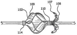
Fig. 1 to 3 is axonometric charts of seeing device 100 from three different angles, this device is depicted as and is in its complete deployed condition, without any radial constraint (it will be subjected to radial constraint in the delivery catheter such as being contained in when this device, perhaps be subjected to the constraint than littler degree in auricle).Fig. 4 is the end-view cup-shaped concave side, device 100 of the near-end of finder 100.
As described in inciting somebody to action further, device 100 can be made by a plurality of single sections of flexible endurance wire rod 101.In certain embodiments, device 100 near-end can have nearside eyelet 114 and with the distally eyelet 113 of the far-end adjacent positioned of device 100.Inner chamber is extensible by eyelet 113 and 114, and passes through the length of device 100.Device 100 also can have the inaccessible parts 104 and the one or more anchor logs 106 that are positioned at relative far-end with the near-end adjacent positioned, and inaccessible parts 104 and one or more anchor log 106 are separated by hub 110.Inaccessible parts 104 can comprise a plurality of flap things 112, and each flap thing 112 has the expansible framework 102 that the part by the length of wire rod 101 constitutes.Each flap thing 112 can be coated with or be coated with basically diaphragm element 109, and this diaphragm element is by expansible framework 102 supportings.In certain embodiments, single barrier film covering 109 can be used for covering basically all a plurality of flap things 112.
In certain embodiments, one or more anchor logs 106 and/or barb 211 contact with wall or the body of left auricle.In certain embodiments, the contact point between anchor log and/or the barb is the endocardial surface that is positioned at left auricle.Although one or more anchor logs and/or barb thrust the endocardial surface of left auricle in certain embodiments, in some other embodiment, do not thrust endocardial surface.In certain embodiments, some anchor logs of device pierce through endocardial surface, and other anchor log of device does not pierce through endocardial surface.In certain embodiments, some Rubus delavayi Franch. punching intimal surfaces of device, and other barb of device does not pierce through endocardial surface.In certain embodiments, one or more anchor logs contact with the girder formation (trabeculation) of endocardial surface.
In certain embodiments, one or more barbs 106 are made of the part of the length of wire rod 101.In certain embodiments, two or more, three or more, four or more, five or more, six or more, seven or more, eight or more or nine or more anchor log is stable and/or fixture 100.Other example of anchor log is provided below.
In certain embodiments, one or more anchor logs 106 have ring formation end 107, and are provided with barrier film covering 108 in the part of each anchor log 106.
Fig. 1 to 4 illustrates the embodiment of locking device 100.In some embodiment of device 100, device construction has expansible framework 102.Expansible framework comprises nearside eyelet 114 and distally eyelet 113, cup-shaped inaccessible parts, one or more anchor log and the boss assembly between inaccessible parts and described one or more anchor log.Expansible framework 102 can form with the virtually any size that is suitable for using.Usually, the size range of people's left auricle oral area is from about 10 to about 32 millimeters, and average out to is just being broken a promise 4 millimeters for about 21 millimeters.Plant bulk can manufacture the gamut that comprises finish dimensional.Expansible framework 102 can be formed by endurance wire rod 101 structures of any number.In certain embodiments, a plurality of wire rods, for example four, five, six, seven, eight, nine or more wire rod install for the manufacture of this.Expansible framework 102 is formed in certain embodiments by rubber-like wire rod, for example endurance wire rod structure, expansible framework 102 is formed by rubber-like wire rod structure, elasticity allow expansible framework 102 collapse to carry out based on conduit send or thoracoscope is sent, then in case in being positioned at intracavity with regard to the structure of self expandable to expectation.Elastic wire can be spring wire, shape memory allow wires or superelastic alloy line.But can adopt and have bio-compatible feature and firm, flexible and elastic any wire rod.Wire rod can for example be Nitinol (NiTi) but, L605 steel, rustless steel or any other bio-compatible wire rod.Elastic wire can also be the drawing-filled-type Nitinol that comprises different metal at core.It is effective material for this application that the super-elasticity of Nitinol makes it.But the thermosetting of Nitinol wire rod becomes the shape of expectation.STAINLESS STEEL WIRE is the material that substitutes.It can be plastically deformed into the shape of expectation.Also can use and utilize the centerless grinding technology to be configured as the wire rod with diameter change.Other shape memory or plastically deformable material can be suitable for this application.
In certain embodiments, expansible framework 102 can be formed by the not drawing of the saturating radiation metal-filled-type NiTi wire rod structure that comprises in the center such as platinum.Upon deployment, wire rod structure recovers the shape of its expansion, and permanent deformation not.
Other embodiment of expansible framework 102 and expansible framework can constitute by having the about 0.12 elastic wire material to about 0.14 millimeter overall diameter (OD).Other embodiment can be made of about 0.2 wire rod to about 0.3 millimeter OD.
As used herein, term " about " refer to fall into set-point+/-5% or+value in/-10% restricted portion.
When forming, expansible framework 102 comprises nearside eyelet 114, distally eyelet 113, cup-shaped inaccessible parts 104, boss assembly 110 and anchoring element 106.Cup-shaped inaccessible parts 104 are designed to seal effectively or inaccessible left auricle.As used herein, " cup-shaped " refers to the uneven inaccessible parts 104 as seeing when device 100 launches without restrictions.The cup-like shape of inaccessible parts 104 is configured to strengthen the sealing around the oral area edge of left auricle, and with the sidewall of the left atrium of heart and put.Cup-shaped inaccessible parts 104 have spill or convex configuration, this structure allow the multiformity of plant bulk and promote device in the left auricle oral area from centering.Have the inaccessible parts 104 of concave configuration shown in Fig. 1 to 4.Inaccessible parts 104 with convex configuration shown in Figure 6.
The elastic wire that the presets structure of expansible framework 102 allows framework to reverse upon deployment.This reversing formed flap thing 112.The flap thing 112 that launches forms the overall diameter 120 of expansible framework 102.The flap thing 112 that launches forms cup-shaped blocking element 104 when being coated with diaphragm element 109.In certain embodiments, flap thing 112 forms has overlapping region, to improve airtight quality.The radius of flap thing 112 and shape can be optimized to the sharp bend angle that makes in the elastic wire and reduce to minimum, and make the not support section of flap thing 112 reduce to minimum with the airtight quality that improves device, reduce the flexural fatigue of wire rod and help to reduce the device loading force.
In the embodiment described in example 1, during constructing apparatus, shown in centrepin 22 and flap thing anchor clamps 38(Figure 11) outer surface between the longest distance formed the radius of inaccessible parts.Although five flap things are arranged in certain embodiments, two, three, four, six, seven or eight or more flap thing are arranged in certain embodiments.In certain embodiments, at least one in the flap thing is coated with diaphragm element 109, to suppress blood by the flap thing.In certain embodiments, each flap thing is coated with diaphragm element at least in part.In certain embodiments, each flap thing is coated with diaphragm element fully.Be convenient to make device suitably to locate and settle by cup-shaped blocking element 104, and this location and settle and suppress blood flow and flow through device or at winding apparatus.
Adopt a plurality of wire rods to come some embodiment of constructing apparatus, these wire rods extend in the whole length of device, produce the expansible framework of single type thus.Perhaps, the multi-piece type embodiment of device can construct by proximal portion is attached to extremity at hub 110 places, for example two-piece devices.When producing two-piece devices, proximal portion can be connected in many ways with extremity.Proximal portion can comprise inaccessible parts, nearside eyelet and hub alternatively.Extremity can comprise one or more anchor logs, distally eyelet and boss assembly alternatively.Proximal portion and extremity can link in the following way, and for example expanded polytetrafluoroethyl,ne (ePTFE) film that fluorinated ethylene propylene copolymer (FEP) is applied is wound into two parts are linked together, and heat to form firm bonding then.In certain embodiments, each sheet links by concentric fit, wherein, a slice is threaded or is press fitted in another sheet.In certain embodiments, adopt two-piece type structure that each sheet in each sheet forms with different wire rod types or diameter for example, in certain embodiments, but the device specialized designs becomes to have than the blocking element anchoring element of rigidity more.That is, extremity can be configured with than being used to form more (for example, larger diameter) wire rod of rigidity of proximal portion.
The flexible connector zone 124 that proximal portion and extremity also are used between the two elements connects.In such an embodiment, proximal portion has and is configured to suppress the diaphragm element that blood passes through and the expansible framework that is made of a plurality of wire rods, this expansible framework has the cup-shaped inaccessible parts 104 that are coated with diaphragm element at least in part, and this proximal portion is connected to the extremity with one or more anchor logs 106 by at least one flexible connector and/or hub.This connector can comprise hinge, spring and joint.
In certain embodiments, flexible connector zone 124 is positioned at hub 110 places or below.In certain embodiments, by being wound in spring-like, the wire rod between proximal portion and the extremity constructs link.The spring-like structure can form in the following way, namely, wound wire forms eyelet 142 and forms eyelet 144 at the proximal portion place of anchoring members 106 with the extremity place at cup-shaped blocking element 104, between two eyelets 142,144 shown in Figure 15 A additional coiling 140 is arranged.
Figure 15 B is longitudinal sectional view, and this figure further is illustrated in the extremity place perforation 142 of cup-shaped blocking element and at the structure of the proximal portion place of anchoring element perforation 144, these eyelets separate to illustrate the insertable space of flexible connector.Then, can cut additional coiling 140, to change the performance characteristic of middle springs shape portion section.The spring-like center section also can not form perforated anchoring members and forms by wire rod directly is wound into from cup-shaped blocking element.The spring-like connector can separate formation with cup-shaped obstruction component and anchoring members, and by on the eyelet that is interference fit into the extremity place that is positioned at cup-shaped blocking element 142 and be positioned on the eyelet at proximal portion place of anchoring element 144 or on the interior diameter of eyelet 142 and 144 and be secured to cup-shaped obstruction component and anchoring members, as shown in Figure 15 C and 15D (in Figure 15 C not shown 144).This connection can be strengthened by increasing securing member, and securing member comprises for example glue or adhesive tape.
In certain embodiments, flexible wire rod connector is made of the wire rod that forms the flap thing 112 shown in Figure 16 A, and hinged arrow 146 indication devices can be along its longitudinal axis bending.In this structure, flexible wire rod is continuous to anchoring members 106 through flexible connector zone 124 from flap thing 112.In certain embodiments, this structure comprises attaching means or the flexible pipe 148 that fits loosely in around the flexible connector zone 124, as shown in Figure 16 B.Attaching means can be by any suitable material structure that is used for flexible pipe as described herein.
Link can for example be made of two wire loops 126, and these wire loops form and are similar to a kind of connection that is connected with the chain link as shown in the 17B as Figure 17 A.Wire loop 126 can be for example by any suitable binding agent, be fixed in the eyelet by welding or by mechanical connection.Alternatively or additionally, wire loop 126 can be made of the one or more wire rods that form eyelet.The connection of chain nodal pattern can be covered (range of movement roughly is by arrow 127 expressions) or be uncovered as shown in Figure 17 A by coiled casing 128 as shown in Figure 17 B.But the material that is used for this sleeve pipe 128 can be any material with suitable bio-compatibility and fatigue properties, such as following about those listed materials of flexible pipe connector.
As shown in Figure 18 C and 18H, coil form flexible connector 138 can be used as flexible connector.This connector can be made by any suitable material.In certain embodiments, this connector is made by being similar to the Nitinol wire rod that is used to form cup-shaped blocking element 104 and anchor log 106.Coil form flexible connector 138 can be constructed with the eyelet 142 at the extremity place that is positioned at cup-shaped blocking element and be positioned at the pitch of eyelet 144 at proximal portion place of anchoring element and diameter and the coil pitch of diameter coupling, be fixed in two eyelets 142 and 144 or on.As shown in Figure 18 H, this connector 138 can be as described below be used to tactile feedback and length adjustment are provided.
In certain embodiments, flexible connector is made of the wire rod that is wound into tubular spring-like structure.Some embodiment comprise and adopt two or more, four or more, the six roots of sensation or more or eight or more filaments.In certain embodiments, used thread wire rod have about 0.1 millimeter to about 0.3 millimeter overall diameter.In certain embodiments, flexible connector is made by flat wire rod.In certain embodiments, flexible connector is to comprise for example along the interior diameter layer of two opposite pitch directions extensions and the multi-ply construction of the flat wire rod of overall diameter layer.In certain embodiments, flexible connector is the structure that comprises the flat wire rod with fabric.
Flexible connector shown in Figure 18 A-18H also can be used for changing the length between the eyelet 144 at the proximal portion place of the eyelet 142 at the extremity place of cup-shaped blocking element and anchoring element.In certain embodiments, with that limit and known length setting, they can provide the contact feedback to pearl type flexible chain connector (135,136), simultaneously the length in the middle of the adjusting device to each other.This system is shown in Figure 18 G, and a section in the interior diameter that one of comprises in the insertion eyelet 142 and/or 144 of hypotube (hypotube) 131 or other suitable flexible material, protuberance 133 was to provide tactile feedback in this section was constructed with during length adjustment.In certain embodiments, device construction becomes for example to allow rotation motility and/or length adjustment, as shown in Figure 18 G, the manipulation that some embodiment of device allow the discrete pearl on 130 to carry out owing to the implantation clinician is passed deformable door and was carried out length adjustment at 133 o'clock.In certain embodiments, also can adopt screw type mechanism to regulate length, in this mechanism, 138 coil passes the screw thread on 144.In certain embodiments, flexible connector allows to rotate motility and length adjustment.
Flexible pipe can be any suitable polymers.In certain embodiments, pipe is ePTFE.As shown in Figure 19 A-19B, this flexible pipe of being made by ePTFE 150 can be connected on the eyelet 144 at the eyelet 142 at the extremity place that is positioned at cup-shaped blocking element and the proximal portion place that is positioned at the anchoring element (not shown), and adopts the various means described in the literary composition to fix.In certain embodiments, the ePTFE pipe has one or more tight sections.Pipe can be knitting polymer pipe, wire harness or strand.Pipe also can be made by shrinking pipe fitting 152, such as, but not limited to being to extrude PTFE, strengthen silicone 153(Figure 20 A) or the PTFE film of the spiral type winding as the longitudinal sectional view among Figure 20 B as shown in.But reinforcement 151 can be formed by any biocompatible metal structure such as L605, SST, 316L etc.Shrink pipe fitting 152 and can be attached to eyelet 142 and 144 by interference fit or pressure fitted or by any suitable binding agent.Pipe can have the ripple that is similar in the bending straw those.Ripple can cover in metal tube or the polymer.Metal tube 154 can be the hollow pipe that spiral type is twined, and it has the filament that one or more layers spiral type as shown in Figure 20 C-20D is twined.Metal tube 154 can also be the cutting attachment tube (hypotube) that is multiple pattern shown in Figure 15 E.This pipe can be configured at one end or the place, two ends has flange 156, so that be attached to the eyelet 142 of cup-shaped obstruction component and the eyelet 144 of anchoring members.
In certain embodiments, flexible connector stretches out the eyelet that passes inaccessible dish and anchoring structure.In certain embodiments, flexible connector comprises the cap of the end that is installed to hypotube.In certain embodiments, cap welded, for good and all fix (superglue, FEP) in flexible connector.In certain embodiments, end cap prevents device feature (that is, flap thing supporting member and anchor log) motion through the device end points of their correspondences, but allows moving and the rotation of the longitudinal axis of winding apparatus along the longitudinal axis of device.In certain embodiments, flexible connector comprises internal interval spare, in case each parts of the far-end of locking apparatus are interfered, rubbed or contact with each parts of the near-end of device.In certain embodiments, internal interval spare is physical separation part or the surface of polishing, to limit each parts along the range of movement of the longitudinal axis of device.
In certain embodiments, flexible connector is hypotube.In certain embodiments, hypotube has from about 0.06 " to about 0.08 " overall diameter.In certain embodiments, hypotube have from about 0.1 millimeter to about 0.2 millimeter wall thickness.In certain embodiments, hypotube can be born the tension load of 2.2 pounds (10N).
In certain embodiments, flexible connector 158 is made by the flexible material such as silicone or polyurethane as shown in Figure 20 E.This connector can have matched in clearance, so that the eyelet 142 at the extremity place that it can be by being positioned at cup-shaped blocking element and the eyelet 144 that is positioned at the proximal portion place of anchoring element insert.By using the flange 162 or the attached cap 160 that form that this connector is fixing in place.In certain embodiments, one or two in this structure permission anchoring members or the cup-shaped blocking element rotates independently of one another.As shown in Figure 20 G, silicone also can be used for forming the flexible connector 164 of molded (overmold, the encapsulate mould) type of coating.Can for example by typical over-mold process this connector be attached in eyelet 142 and 144 places.
At the structure 166 that substitutes shown in Figure 20 F.Silicone or polyurethane molding plug-in unit can insert with attached to be similar to aforesaid mode.This plug-in unit can have the diameter of increase in flexible coupling place.
The flexible connection element can also be the universal joint the ball-and-socket type shown in Figure 20 H is constructed.Cloudy female component 168 can fix or be attached in the eyelet 142 at the extremity place that is positioned at cup-shaped blocking element by any suitable means described in the literary composition.Ball and axle 170 are installed in the cloudy female component 168, and whole universal joint is covered by coiled casing 172.Coiled casing 172 can be any coiled casing described in the literary composition.
In certain embodiments, one or more flexible connectors can be by adopting shown in threaded cap 174 and 180(Figure 21 A and the 21B) fix or be attached to eyelet 142 or 144.One or more threaded caps can adopt threaded insert 176 to be secured to flexible pipe 178, and this threaded insert has for example multiple-threaded geometry, and it has and eyelet 142 and the 144 pitch coils that mate.This structure can be used for conduit attached or device location or bonding.Threaded cap 180 is similar to threaded cap 174 structures.Threaded insert 184 is positioned on the interior diameter of eyelet 142 or 144, and flange 182 is used for threaded cap 180 is fixed to eyelet 142 and 144.
In certain embodiments, flexible connector is made by the compression spring.As shown in Figure 22 A, compression spring 186 can be configured with matched in clearance, inserts by the interior diameter of the eyelet of device to allow spring.Figure 22 A has for the sake of clarity described with the connector part shown in the cutaway view.The spring structure can have flexible wire rod or filament diameter and wire rod or the filament sum of the expectation of realizing.In this example, coil is by keeping cap 190 to be held in place, and this maintenance cap can cooperate to be attached to the compression spring by binding agent or screw-type in certain embodiments.Element 188 is can be by shrinking the flexible connection part that pipe fitting, PTFE membrane structure, silicone or any other suitable material are made.This connector can be configured with ripple as mentioned above.If made by silicone, flexible connection part 188 can optionally use the metal such as wire rod or strand structure to strengthen.But this wire rod or strengthen and to be formed by the metal construction such as any bio-compatible of L605, SST, 316L etc.
As shown in Figure 22 B and 22C, the alternate configuration of above-mentioned compression spring can replace compressing spring 186 and have line or filament 192.End cap 190 can form porose, to allow filament 192 to pass through and to fix.Perhaps, as shown in Figure 22 C, line or filament 192 can pass eyelet 142,144 inner chamber, and such as being fixed by tuberosity 194.
Device 100 can be sent by conduit system in mode in the blood vessel, and this conduit system comprises the delivery catheter 115 that is positioned at delivery sheath 117 with one heart.Device 100 can be loaded in the delivery sheath by some kinds of methods.A kind of method is that device 100 is loaded on the delivery catheter 115, and anchor log 106 is stretching, and cup-shaped inaccessible parts 104 are collapsed along the direction opposite with anchor log, will install then with delivery catheter 115 and insert as shown in Figure 7 in the delivery sheath 117.Other method is that device 100 is loaded on the delivery catheter 115, cup-shaped inaccessible parts 104 are collapsed and make anchor log 106 collapse or press along the direction identical with cup-shaped inaccessible parts 104 and collapse, then the device 100 on the delivery catheter 115 is loaded in the delivery sheath 117.The another kind of method of sending is that cup-shaped inaccessible parts 104 are extended along delivery catheter 115, and folding or press the anchor log 106 that collapses as previously mentioned, as shown in Figure 8 the device 100 on the delivery catheter 115 is loaded in the delivery sheath 117 then.In certain embodiments, other method that adopts exchange fast or send on the known guide line to those skilled in the art comes on guide line 119 delivery apparatus (referring to the United States Patent (USP) the 5th of for example Yock, 040,548,5,061,273 and 6,165, No. 197 and No. the 4th, 762,129, the United States Patent (USP) of Bonzel).In certain embodiments, when being positioned to send, device 100 anchor log is to the far-end location of delivery catheter 115, and device and delivery catheter 115 are positioned in the delivery sheath 117, in the far-end of sheath 117.
In certain embodiments, release the expansion that the delivery sheath 117 that remains on constant position is come implement device by installing with delivery catheter 115.In certain embodiments, can realize sending by the position that makes delivery sheath 117 withdrawals, maintenance simultaneously be loaded into the device on the delivery catheter 115.In certain embodiments, can imagine and delivery catheter 115 is released anchor logs 106 retract the combination that delivery sheath 117 is launched cup-shaped blocking element 104 simultaneously.In in these method of deploying each, anchor log 106 will at first launch, and cup-shaped blocking element 104 launches and is placed in the oral area then.Can be imagined other method of expansion by those skilled in the art.Mandrel or the delivery catheter of band key can be used for sending.In this structure, the inner chamber of device can be configured as the form fit with mandrel or conduit, to improve the control of device during launching.These devices can be suitable for using with preformed orientable, flexible or steerable delivery sheath and/or the conduit that can buy.
In certain embodiments, it is not shown that the key of eyelet cap 212 is designed to the delivery sheath 115(of appropriate size) connect (referring to Figure 26) at keyhole 213 places with eyelet cap 212.The deployment schemes that substitutes relates to launches inaccessible parts in left atrium, keep anchor log to be tied simultaneously.Device will advance near cup-shaped inaccessible parts are positioned over oral area, anchor log is launched then.This expansion situation will adopt preceding method that device is loaded on the delivery catheter 115.
In certain embodiments, device construction becomes can reorientate maybe after being delivered to the mouth position of left auricle and can recall.Recovery line can then break into ring by the near-end that diaphragm element 109 returns to continue to turn back to delivery catheter 115 by inner chamber and by nearside eyelet 114 from the near-end of delivery catheter 115, and at this, this line can be handled by the operator.But recovery line can be made by any biocompatible materials of sufficient intensity and size.This material comprises fluoropolymer and intumescent fluoropolymer and compositions thereof, such as expanded polytetrafluoroethyl,ne (ePTFE).Recovery line can be used for helping when the device part is launched device being reorientated.This can be by tractive recovery line gently two bring in realization what its near-end from delivery catheter 115 left.When device launched fully, recovery line also can be used for retraction mechanism.Deployed device is the device that launches or pull down from delivery catheter fully.Recovery line passes device in expansion process nearside eyelet 114 breaks into ring, and if necessary can be used for whole device is withdrawn in the delivery sheath 117 after expansion.
As Fig. 1 to 4 with as shown in Fig. 6, diaphragm element 109 is configured to suppress blood to be passed through.Embodiment can provide diaphragm element 109, and this diaphragm element 109 constitutes inhibition blood by barrier film, that is, obturation is by the blood flow of barrier film basically.Some embodiment can provide diaphragm element 109, and this diaphragm element is configured to cause growth in the quick tissue, even the quick inaccessible blood of existing side by side passes through barrier film.In certain embodiments, diaphragm element 109 provides the barrier film of not saturating blood or human body fluid, this barrier film inaccessible blood flow or human body fluid stream by barrier film, but also promote growth and endothelialization in the tissue.This embodiment can comprise the fluoropolymer such as the expanded polytetrafluoroethyl,ne polymer.In certain embodiments, suppressing blood or human body fluid is (directly) immediately by diaphragm element 109, and does not rely on the thrombosis process.Diaphragm element 109 also can be used as growth support in the tissue, with inaccessible and this device of grappling enduringly.The multi-cellular structure of diaphragm element 109 can specialized designs become to promote growth and/or endothelialization in the tissue.Diaphragm element 109 can be revised by various chemistry or physical process, to strengthen certain machinery or physical characteristic.Hydrophilic coating may be used on diaphragm element 109, to promote its wettability and to imitate translucent.In addition, can adopt physical chemistry to revise, diaphragm element 109 comprises chemical part thus, and these chemical parts promote that endotheliocyte is attached, move and/or breeding, or antithrombotic forms.The surface of revising with the covalent bonding heparin is the non-limiting example that barrier film is revised.In certain embodiments, barrier film is impregnated with one or more crude drug, and these crude drug discharge to improve healing reaction or reduce tissue inflammation on the spot.In certain embodiments, crude drug is selected from following group: corticosteroid, people's somatomedin, antimitotic agent, dexamethasone sodium phosphate and antithrombotic.
But diaphragm element 109 can be made by any biocompatible materials, but biocompatible materials comprises the fluoropolymer such as politef and expanded polytetrafluoroethyl,ne; Polyester; Silicone; But polyurethane or other bio-compatible polymer and compositions thereof.Some embodiment comprise diaphragm element, and diaphragm element comprises the fluoropolymer such as politef and expanded polytetrafluoroethyl,ne.In certain embodiments, diaphragm element comprises expanded polytetrafluoroethyl,ne.
Some embodiment of boss assembly 110 of the present invention are made of the complex of Nitinol wire rod and film.In certain embodiments, boss assembly 110 is made of wire rod.Being configured in the example afterwards of the complex embodiment of boss assembly described in detail.Some embodiment of device comprise along the central axis of expansible framework or the inner chamber 122 that extends in parallel.In certain embodiments, the size of inner chamber can be designed to allow the guide line of about 0.9 mm dia to pass through, so that carry out coaxial alignment in such as the body cavity of left auricle.Inner chamber is by nearside eyelet 114, cup-shaped inaccessible parts 104, boss assembly 110, anchoring members and distally eyelet 113.Inner chamber 122 can pass through wire coil around centrepin 22, form to form by each the hollow centre core in the following element, these elements are: nearside eyelet 114, cup-shaped inaccessible parts 104, boss assembly 110, anchoring members and distally eyelet 113.In certain embodiments, inner chamber 122 allows to carry out in the device back that places
The fluorescent contrast agent injection, so that wedge angle sealing (acute seal) assessment.
Some embodiment of boss assembly 110 can be formed by a plurality of Nitinol wire rod unit architectures that keep together by fluoropolymer or various flexible fluoropolymer such as expanded polytetrafluoroethyl,ne (ePTFE).In certain embodiments, plug element and the multicomponent structure that keeps together allows to carry out hinged by flexibility between blocking element and anchoring element, be convenient to safer, more stable and more effective obturation thus potentially.In certain embodiments, boss assembly 110 can form by having or do not have obducent continuous wire structure such as Nitinol.
In certain embodiments, one or more anchor logs 106 distad extended simultaneously by outside or radial radiation and comprise at the place, end of anchor log point to nearside reversing for a short time or a plurality of wire rods of little turn of bilge constitute.In certain embodiments, anchor log 106 is made of ring formation wire rod (referring to Fig. 1-4 and 6) or independent wire rod radiation (referring to Fig. 5 B and 5C).In certain embodiments, the nearside of ring reverses and can be approximately perpendicular to forming to extraradial angle of one or more anchor logs.In certain embodiments, one or more the exposing in the anchor log 106.In certain embodiments, one or more whole in the anchor log 106 or partly be coated with barrier film 108.In certain embodiments, anchor log is not coated with barrier film (referring to, Fig. 8 for example) basically.In some devices, have exposed and be coated with/part covers septate anchor log.In certain embodiments, the barrier film 108 of ring formation anchor log 106 prevents that the anchor log shank from loading, launch, regaining and twining in the expansion process again.In certain embodiments, barrier film covering 108 is positioned at around the nearside turn of bilge of ring formation anchor log 106.In certain embodiments, barrier film covering 108 can provide fast and grow and device stability in the tissue.In certain embodiments, the paired wire rod anchor log 106 with ring formation end 107 provides a kind of means of fixture, and it obviously reduces or prevents from organizing perforation or pierce through or the relevant risk of pericardial effusion.In certain embodiments, the radial expansion force that the anchor log element 106 with ring formation end 107 produces owing to the elasticity of wire rod and grappling securely, and termination cooperates or hooks their nearside torsion capacity with left auricle wall and girder.Ring formation end anchor log 106 may be to device with to the wound of surrounding tissue or destroy and caught again under the situation about significantly reducing or launch again.
In certain embodiments, anchor log is the NiTi wire rod.In certain embodiments, the NiTi wire rod has from about 0.008 " to 0.013 " overall diameter.In certain embodiments, the total length of anchor log is from about 0.13 " to about 0.63 ' '.In certain embodiments, the total length that reverses of nearside anchor log is from about 0.1 " to about 0.2 ' '.
In certain embodiments, but anchor log, barb or their each several part formed by the material structure of impermanent biodegradable or bio-absorbable, these materials can be absorbed along with the time again.In certain embodiments, but the bio-absorbable characteristic of anchor log and barb allow growth in initiatively wedge angle is fixed, is convenient to and reduce desirable tissue not or the risk of organ perforation.
In certain embodiments, anchor log and/or barb to the device the junction point place or near have one or more turn of bilges.In certain embodiments, the turn of bilge radius is about 0.06 " to about 0.2 ".
In certain embodiments, anchor log 106 one or more are single line material anchor logs, are non-ring formation wire rod that this wire rod radiates outwardly to cusp or the atraumatic ball 145 that is positioned on the terminal from the nearside center hub.In certain embodiments, one or more in single shank anchor log are comprising at least one dog-leg shape feature to extraradial wire rod element.In certain embodiments, when catching again, dog-leg shape feature is convenient to make anchor log to throw off on sheath being passed dog-leg shape feature.In certain embodiments, the far-end with ring formation end of anchor log can roughly be cut at the place, summit of ring, to form a pair of single line material anchor log (referring to Fig. 5 C).In certain embodiments, the one or more anchor logs with ring formation end have at least one dog-leg shape feature (referring to Fig. 5 A).In certain embodiments, one or more anchor logs have the ring formation end, and comprise two or more turn of bilges (for example, referring to Fig. 5 A) along grappling length.In certain embodiments, a plurality of different radial wire rod anchoring elements are owing to the independence of each anchoring element and other element is given this device advantage.Although do not wish to be limited by theory, suppose that this independence allows anchor log 106 to conform to variable accessory organ's dissection, still keeps firm grappling simultaneously.
In certain embodiments, anchor log comprises one or more hinged features.One or more hinges can be in anchor log be connected to device extremity or along a certain site of the longitudinal length of anchor log or near.In certain embodiments, hinge makes the extremity of anchor log rotate about 0-90 degree at least with respect to its proximal portion.In certain embodiments, hinged feature allows anchor log to install and is fixed to left auricle better.
Some embodiment have the paired wire rod anchor log 200 that has ring formation end 107, and ring formation end 107 is shaped so that the axle of wire rod anchor log 202 has the adjacent wire rod that contacts basically before ring formation end 107 bifurcateds of anchor log.This structure (shown in Figure 23) allows the expansion power that reduces and reorientates power.These embodiment also can reduce the probability of crosstalking or tangling when anchor log was loaded in the conduit before sending.Some embodiment of ring formation wire rod anchor log comprise circular rings end, diamond ring end, pointed ring end and encircle the end side by side.
In certain embodiments, the distance between two of ring formation wire rod anchor log shanks at the place, bottom of anchor log than big in the turn of bilge location of anchor log.In certain embodiments, adopt coreless grinding technology to form distance between two shanks of anchor log.
In certain embodiments, device 100 comprises two or more multi-form anchor logs 106.For example, in certain embodiments, device comprises one or more ring formation wire rod anchor logs and one or more single line material anchor log.
In certain embodiments, the structure set of the anchor log structure that preheats setting and anchor log post-heating is different.
In certain embodiments, anchor log 106 also comprises at least one barb 211, and this barb is fixed to anchor log or is wound on (referring to Figure 25) around the anchor log.In certain embodiments, at least one barb is substantially perpendicular to corresponding anchor log to extraradial angle.In certain embodiments, the barb edge is outstanding away from the direction of the general direction of anchor log.In certain embodiments, barb is the wire rod littler than the wire gage of anchor log 106.In certain embodiments, barb comprises at least one dog-leg shape feature.In certain embodiments, barb terminates in the cusp that is positioned at its far-end.In certain embodiments, barb terminates in its far-end as the atraumatic ball.
In certain embodiments, barb is around anchor log is fixed or be wound on to two or more site, to form ring.In certain embodiments, the ring formation barb comprises the combination of one or more (for example, one, two, three or more) turn of bilge, dog-leg shape portion or hinge or turn of bilge, dog-leg shape portion and hinge.
It will be appreciated that generally becoming is difficult to make device to launch gradually because the part count that is positioned on the device increases in the catheter sheath of finite size.In addition, because barb is positioned to sometimes along extending away from anchor log with the uneven direction of the longitudinal axis of anchor log, so barb may tangle with other barb, anchor log or other device feature.Thus, in certain embodiments, barb configuration becomes to comprise turn of bilge or hinge, thereby barb/pointed tooth is crooked backward along the axis of anchor log in being present in the anchor log sheath time, but outwards launches outside device moves to catheter sheath the time.
In certain embodiments, barb is positioned on the front portion of anchor log, that is, compared with the near-end of device, anchor log is on the part of far-end close to device more.In certain embodiments, be positioned at barb on the front portion of anchor log towards nearside, and in certain embodiments, be positioned at the far-end of the barb facing device on the device near-end.In certain embodiments, be attached to the ring formation anchor log towards the barb of nearside, and in certain embodiments, be attached to single shank anchor log towards the barb of nearside.
It is submissive, immalleable or that part is submissive is immalleable with part that barb can be designed to.In certain embodiments, some or all in the barb are capped or coated with preventing or limiting tissue and pierce through.In certain embodiments, but barb covers or is coated with suitable biocompatible materials, but these materials include but not limited to it is fluoropolymer, polyester, silicone, polyurethane or other bio-compatible polymer or its combination such as politef and expanded polytetrafluoroethyl,ne.In certain embodiments, the barb that applies or cover is provided for structure and the substrate of growing in the barb surrounding tissue.In certain embodiments, the coating on the barb or covering provide the protection that prevents that adjacent anchor log and/or barb from tangling.In certain embodiments, barb apply/be coated with will reduce to against the friction of catheter wall minimum material, help the expansion of device thus and/or recall.In certain embodiments, have the barb at one or more tips coated/cover into and only allow limited tissue to pierce through.In certain embodiments, the covering of barb is impregnated with one or more crude drug, and these crude drug discharge on the spot, to improve healing reaction or to reduce tissue inflammation.In certain embodiments, crude drug is selected from following group: corticosteroid, people's somatomedin, antimitotic agent, dexamethasone sodium phosphate and antithrombotic.
In certain embodiments, anchor log 106 is made by reversing or weave wire harness.In certain embodiments, be arranged in barb on this anchor log by from reversing or litzendraht wire cuts one or draw one or more reverse or the wire harness of litzendraht wire forms.
In certain embodiments, anchor log and/or barb comprise veined surface, to help that device is fixed to surrounding tissue.
In certain embodiments, one or more anchor logs comprise two or more structures that are selected from turn of bilge, dog-leg shape portion, hinge, barb and the superficial makings respectively.
In certain embodiments, the radial structure of anchor log according to the anchor log feature interlock (for example, on whole anchor log length (for example, long-short-long-short)).In certain embodiments, the radial structure of anchor log is according to anchor log feature (for example by structure (for example, ring formation wire rod anchor log-single shank anchor log-ring formation wire rod anchor log-single shank anchor log)) biasing.
In certain embodiments, anchor log is evenly spaced apart, that is, the periphery of the extremity of each anchor log 106 winding apparatus radially equal intervals is opened.
In certain embodiments, anchor log 106 is with the nearside center hub of the angle separating device of the longitudinal axis that is substantially perpendicular to device.In certain embodiments, anchor log 106 is to be the angle separating device between the 20-80 degree with respect to the longitudinal axis that installs, and wherein, the distalis of anchor log extends to and may be through the distally eyelet.
In certain embodiments, each in one or more anchor logs is substantially the same, that is, each anchor log has roughly the same total length, identical planar structure (that is, similarly is with or without one or more dog-leg shape features; Be with or without one or more hinges), with respect to the identical radial angle of the longitudinal axis of device (axis that forms between the far-end of device and near-end) and identical construction (for example, ring formation end anchor log, reverse wire ends or single line anchor log).In certain embodiments, different aspect at least a in total length, planar structure, radial angle or structure of one or more and another anchor log at least in the anchor log.
Some embodiment as shown in Figure 24 have the anchor log 204 of single shank.In various embodiments, anchor log 204 can be made by the wire rod identical with forming eyelet 144.Anchor log 204 comprises axial region 206, radius 208 and wire ends 210.Wire ends 210 can be configured to leave the plane torsion of radius 208 or be outstanding from this plane, to carry out further grappling as barb or protuberance.
Some embodiment provide the ring formation wire rod anchor log 106 with barb 211, and this barb is attached to anchor log (shown in Figure 25) in a plurality of positions.
In certain embodiments, the anchor log wire rod is outstanding from installing at hub flange place.In certain embodiments, the hub flange is coated with and is made for the submissive hub extension that coats molded or pre-moulding part.
The exemplary embodiment of device is shown in Figure 27 A, and this device comprises modular grappling hub 217, this grappling hub is connected to locking device (comprising the flap thing 112 by expansible framework 102 supportings) with anchor log 106, wherein, anchor log 106 axially is installed in the flange 215 (shown in Figure 27 B and the 27B).This modular grappling hub allows to adapt to the type of locking device and type and the form of anchor log fast, and can optimize device based on choice criteria, and choice criteria comprises the locking device of expectation, the anchor mechanism of expectation and size and the dissection of left auricle.In certain embodiments, modular anchoring members has reduced the far-end profile of device, and therefore thrombotic probability is reduced to minimum.
In certain embodiments, the modularity anchoring members is attached directly to locking device, or is attached to locking device by flexible connector.In certain embodiments, the modularity anchoring members allows the different structure of anchor log.For example, in certain embodiments, the modularity anchoring members allows the combination of the single lower limb type of grappling anchor log, ring formation wire rod anchor log and single lower limb and ring formation wire rod anchor log.In certain embodiments, anchor log axially is attached to the modularity anchoring members allows to reduce the device profile, and reduce delivery catheter interior expansion power and retracting force.
In certain embodiments, modularity grappling hub also allows multiple anchor log structure (for example, active or passive geometry, anchor log number, anchor log size, anchor log distribution and anchor log length and anchor log are installed to hub).In certain embodiments, the shank of ring formation wire rod anchor log is adjacent one another are, namely is in adjacent structure.In certain embodiments, the shank of the first ring formation wire rod anchor log is separated from one another by the shank of adjacent ring formation wire rod anchor log,, is in decussate structure that is.Although do not expect to be subject to theory, it will be appreciated that adjacent structure allows anchor log to do more multiple lateral motion, simultaneously the interference between the adjacent anchor log is reduced to minimum, and the structure that " interlocks " provides the hub place wideer supporting, the lateral movement of anchor log is reduced to minimum, and because the interference between the adjacent anchor log provides further lateral-supporting.
In certain embodiments, this device also comprises the eyelet cap of being with key, cooperates with the delivery catheter with suitable band key.In certain embodiments, keyhole 213 is admitted the end of smooth delivery catheter.In certain embodiments, suture hole 218 allows the ring formation suture to pass around the eyelet cap from conduit, so that device is fixed to conduit.In certain embodiments, the axis of screw and eyelet axis bias are with the torque to device that reduces to produce in dispose procedure.
In certain embodiments, the eyelet cap comprises sleeve pipe and end cap cover, and they are made by Nitinol or other suitable materials respectively.Sleeve pipe is arranged on around the eyelet, and in certain embodiments, welds or be adhered to eyelet.In certain embodiments, sleeve pipe comprises the one or more grooves that radially are arranged on around the sleeve pipe, and each groove extends downwards to sleeve pipe along the axis of device.In certain embodiments, groove is provided for the path that welds and/or bond.In certain embodiments, sleeve pipe cooperates with in the framework wire rod each, and helps to keep the desired spacing between the framework wire rod.
In certain embodiments, install assembly process, before bag is attached, increasing sleeve pipe, and assembling increase end cap cover when finishing.In certain embodiments, end cap cover is attached to sleeve pipe by card combo dress, and wherein, the one or more lugs on the sleeve pipe cooperate with the flange on the end cap cover.In certain embodiments, lug and flange are aimed at, with suitable aligning and the calibration between checking nearside and the distally eyelet.
Some embodiment comprise appropriate plastic material (for example, thermoplastic or fluoropolymer) coated and are molded on the sleeve pipe.In certain embodiments, coat molded comprising for the attached one or more zones of fluting slightly of bag.
In certain embodiments, installation optimization becomes to have specific inaccessible dish diameter and device length ratio.In certain embodiments, the ratio of inaccessible dish diameter and device length is that 1:2 is between the 2:1.In certain embodiments, the dish diameter is 1:1 with the device length ratio.In certain embodiments, the waist length (for example, the distance between the start-up portion of the distally of the inaccessible dish of nearside and grappling protuberance) with device is adjusted to the ratio that produces expectation.
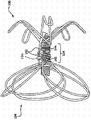
As shown in Figure 9, some embodiment provide and are configured to suppress the diaphragm element that blood passes through and the expansible framework that is made of a plurality of wire rods, expansible framework has cup-shaped inaccessible parts, has one or more anchor logs 106 and the boss assembly 110 of ring formation end 107, and these obturation parts have smooth proximal face 116 and are coated with the cup-shaped distal surface 118 of diaphragm element 109 at least in part.That this structure can allow is darker, be placed in the left auricle oral area more firmly, also eliminate simultaneously may be the root that forms of thrombosis or blood clot by the left auricle stump.
Example 1
Obtain 10% about 1 meter long platinum drawing-filled type Nitinol wire rod (the Fort Wayne metal company of state of Indiana Fort Wayne (Fort Wayne Metals)), this wire rod has and is about 0.23 millimeter diameter.Can measure or not measure the concrete length of wire rod, but wire rod should be long enough to finish as in the coiling pattern described in the following paragraph.Obtain to have carried out the wire rod of electrobrightening.The Nitinol wire rod of electrobrightening is given the characteristic of necessarily knowing, and such as naturally and understandably forming titanium dioxide layer from the teeth outwards, optionally reducing the nickel amount on the wire surface and remove certain stress in the wire rod, improves tired thus.
Obtain base clamp 8 as shown in Figure 11.In the end knotting of the length of about 0.5 meter long wire rod, and that end of will not tie a knot is presented by wire rod feed hole 10.With two additional line segments (being respectively about 1 meter) folded in half, and free end presented by all the other four feed holes 12,14,16,18, wire rod enters the hole at choana 19 places, at the place, bottom of opening 19 little feed hole is arranged.Then, wire rod leaves by hole 10,12,14,16 and 18 at the flat end place of anchor clamps 8.Weight 20 is attached to the free end of five wire rods, to keep wire rod tension and in place.Base clamp is fixed in the chuck of lathe, and centrepin 22 is inserted in the kingpin hole 24 as far as being enough to settle this centrepin securely.
The other end of centrepin 22 is positioned at clip to the centre bore 28 of the tailstock supporting member 26 of tailstock, and wherein, the closing face 30 of tailstock supporting member 26 is towards base clamp 8.Base clamp 8 and tailstock supporting member 26 are positioned to separate about 5 centimetres.Wire guide part 34 is used for preventing that wire rod from intersecting.Be positioned to make wire rod feed hole 10,12,14,16,18 to be vertically located in centrepin 22 tops base clamp 8, and wire rod be positioned at the tail side of centrepin 22.
720 degree (degree) are rotated in flap thing anchor clamps hole 36.Flap thing anchor clamps 38 are inserted flap thing anchor clamps hole 36.Under the Uncrossed situation of wire rod, wire rod is positioned on flap thing anchor clamps 38 tops.Base clamp 8 rotates 360 degree with the flap thing of generator.Base clamp 8 rotates 720 degree again, and wire rod is positioned on the top of centrepin 22, to produce central aperture.
Next, anchor pin 40 is inserted in the grappling pin-and-hole 42.Then, wire rod is ring formation around anchor pin 40, and base clamp 8 is rotated 720 spend to form the distally eyelet.Wire rod pivotal part 7 is inserted in the wire rod pivotal part hole 9.Wire rod is fed to around the wire rod pivotal part 7, and is placed on anchor plate 11 times.Fix anchor plate 11 with Alan's head thread spare 14.Weight 20 sides at anchor plate 11 are cut off wire rod.
Removing weight 20,, under the situation of tailstock supporting member 26 and wire guide part 34, this assembly can for example be positioned in the convection furnace that is set to 475 degrees centigrade 14 minutes.Remove this assembly from stove, and in water cold quenching.Clamper for disassembling, and remove object.
Wire ends is cut into eyelet, and flap thing edge direction fan-shaped scatter identical with spiral wound, thereby each flap thing is orientated with respect to adjacent flap thing skew 72 degree.Because the flap thing is fan-shaped to scatter, the anchor log ring is fan-shaped scattering also.
Obtain the thermosetting mandrel 44 described in Figure 12 B.Object is positioned on the thermosetting mandrel, thereby, cap 46 and anchor log ring adjacent positioned.Then, object is positioned in the thermosetting instrument 48 (referring to Figure 12 A and 12C), thereby the flap thing is positioned in the thermosetting instrument, and the anchor log ring is outstanding at the lip of thermosetting instrument 48.Anchor log battle pin 50 was inserted the anchor log ring, and was fixed in the anchor log pin-and-hole 52.Thermosetting mandrel 44 is inserted on the centre bore of cross bar 54 (Figure 12 D), and cross bar 54 is placed in the recess 56 of thermosetting instrument 48.Thermosetting mandrel 44 is pushed in the thermosetting instrument 48, and to realize the expected angle of anchor log, it is in place to adopt hold-down screw 58 that mandrel is locked then.
With this assembly be positioned over be set to 475 the degree convection furnaces in 5 minutes, transfer to 2 millimeters mandrel then.
When keeping flap thing orientation, object powder coated as follows has FEP powder (being obtained by inner stock).Obtain the mandrel of 2 millimeters overall diameters, this mandrel has is enough to be inserted in the length in the further described blender in this section.Mandrel 123 is by carrying out wrinkling flattening in spaced apart two about 2.5 centimetres positions.Referring to Figure 13 and 14.Mandrel 123 is inserted the centre bore of object.Grind an end to mandrel 123.The blender that acquisition can be buied (the variable velocity laboratory blender of the Wo Ning company (Waring) of Connecticut TWB), and add a certain amount of FEP powder, thus the end of blender blade is exposed.Object and mandrel are suspended in the mixer center, change lid, and blender is switched to the highest setting value about 5 seconds.Remove object and mandrel 123, the mandrel tapping to realize more uniform powder coating, was suspended on object and mandrel 123 in the convection furnace that is set to 320 degrees centigrade 3 minutes then.Remove object and mandrel 123 from convection furnace, allow to cool off, remove mandrel then.Remove unnecessary FEP from mandrel, and mandrel inserts object again.
By grasp nearside eyelet and central aperture with tweezers object length on mandrel 123 is extended.By eyelet being positioned to exceed in the mandrel wrinkling that eyelet is fixing in place.
Acquisition has the porous ePTFE film of following characteristic:
0.7psi(methanol bubble point pound/square inch)
2.43 the gram/square metre mass/area
Vertical substrate hot strength of 96000psi
The substrate hot strength along orthogonal direction of 1433psi
1.6 vertical maximum load of kilogram/inch
0.00889mm thickness
Employing has the custom machine of slope 1 inch diameter class (diameter foot), 0.2psi/ second and liquid METHANOL MEDIUM and measures the methanol bubble point.Adopt the metal chi to measure length and the width of material.Adopt balance (the model GF-400 top-loading balance of the ANG of Jennings technology), measure mass/area with the sample of 36x5 inch.The material testing machine (model 5564 of the Instron in Ge Luofu city, Pennsylvania) that 10 kilograms of load cells are equipped with in employing is measured vertical maximum load.Gauge length is 1 inch, and crosshead speed is 25 mm/min.Specimen width is 1 inch.Length direction along material carries out the longitudinal stretching test.Adopt 1/4 inch
Diameter classThickness gauge (Mitutoyo digital indicator 547-400) measure thickness.Adopt following equation to calculate vertical substrate hot strength (MTS):

Wherein, ρ
PTFE=2.2 grams/cubic centimetre
σ
Sample=(maximum load/width)/thickness
ρ
Sample=(mass/area)/thickness
Adopt the formula of density=mass/volume to come bulk density.
30 millimeters film pipe is made by the ePTFE material as follows.For the device of 25 mm dias, the film that will have about 1.905 centimetres slot width is wound on the mandrel of 30 millimeters overall diameters.The overlapping amount of film is unimportant, but certain at least overlapping of marginal existence preferably.Then, remove pipe from mandrel, and pipe is stretched the interior diameter of pipe is made about 25 millimeters.
The film pipe is slided at the object of tensioning, and adopt the ePTFE film, the end hoop of pipe is tied up around two eyelets.
Acquisition has another porous ePTFE film of FEP layer, and this film has following characteristic:
36.1 the gram/square metre mass/area
12.6 the maximum longitudinal load of kilogram/inch
0.3 the maximum transversal load of kilogram/inch
0.0012 the thickness of inch
The method of testing that is used for above-mentioned test has been described in the front.FEP thickness in the film is about 62.5%.FEP thickness (%) is calculated as the ratio of FEP thickness and film thickness.The value of reporting has represented the average measurement value of five samples.The electron microscope image of the cross section by scanning ePTFE/FEP stacking material is measured FEP thickness and film thickness as follows.Amplification is chosen to observe whole film thickness.On the whole thickness of film, draw randomly perpendicular to five lines of the horizontal edge of image.Determine this thickness by thickness and the film thickness of measuring FEP.
The band of 2 mm wides that is coated with the ePTFE film (FEP faces down) of FEP is wrapped in for four times around the banding part, and heats so that rete is bonded together by flatiron.
Obtain tubulose porous expanded polytetrafluoroethyl,ne pipe, this pipe has 1.279 millimeters interior diameter and 1.452 millimeters overall diameter.This pipe has following characteristic:
0.531g/cc density
The substrate hot strength longitudinally of 34215MPa
0.086mm thickness
Be positioned over each about 4 millimeters length section of this pipe on each anchor log and as shown in Fig. 1-3 and Fig. 7, locate.
Object and mandrel were placed in the convection furnace that is set to 320 degrees centigrade 3 minutes, remove object and mandrel then and allow to cool off.The ePTFE material that cutting is unnecessary.
Example 2
In the mode identical with example 1, adopt identical materials to construct object, except following difference.The film pipe need not be as pipe, but to its vertical fluting, and the plain film of gained is used for covering the Nitinol framework.Under the situation of not tensioning obstruction component, this sheet is laminated with on the top frame flap thing, and the edge of this sheet is assembled and is fixed to around the central aperture.The inaccessible parts of gained object have cup-shaped inaccessible parts, and as shown in Figure 9, these cup-shaped inaccessible parts have smooth proximal face and cup-shaped distal surface.
Example 3
Except following difference, in the mode identical with example 1, adopt identical materials to construct object.Cup-shaped obstruction component and anchoring members are taken apart each other by clamping central aperture with hands.Obtain diameter and be similar to the ePTFE pipe of the overall diameter of the eyelet shown in Figure 19 A-19B, and be fixed to the distally eyelet of cup-shaped obstruction component and the nearside eyelet of anchoring members.As previously mentioned, the fixing tube that brings that comprises FEP by outsourcing.
Example 4
Except following difference, in the mode identical with example 1, adopt identical materials to construct object.Cup-shaped obstruction component and anchoring members are taken apart each other by clamping central aperture with hands.Obtain diameter and be similar to the ePTFE pipe of the overall diameter of the eyelet shown in Figure 19 A-19B, and be fixed to the distally eyelet of cup-shaped obstruction component and the nearside eyelet of anchoring members.By with the Loctite4011 adhesive coated to the overall diameter of each gained eyelet and the ePTFE pipe is fixed to eyelet till solidifying, fixes this pipe.
Example 5
Except following difference, in the mode identical with example 1, adopt identical materials to construct object.Cup-shaped obstruction component and anchoring members are taken apart each other by clamping central aperture with hands.The diameter ePTFE pipe similar to this overall diameter made by the ePTFE film as previously mentioned.Pipe is fixed to the distally eyelet of cup-shaped obstruction component and the nearside eyelet of anchoring members.Then, with this assembly be heated to 320 degrees centigrade three minutes, thereby allow pipe to shrink and it be fixed to eyelet.
Except relating to above-mentioned and following desired various instructions, also imagine device and/or the method for the various combination of the feature with above-mentioned and following requirement.Equally, the invention still further relates to any other device and/or the method that other may make up of the subordinate feature with following requirement.
The description of front has provided many feature and advantage, comprises various alternative embodiments, and the details of the 26S Proteasome Structure and Function of device and/or method.The disclosure is only represented exemplary and is not expressed as exclusive equally.For a person skilled in the art obviously can be in concept of the present invention in the indicated maximum magnitude of the wide in range upper implication of the expressed term of appended claims, carry out various remodeling, especially in the layout of structure, material, element, parts, shape, size and parts.Do not depart from the degree of appended claims spirit and scope at these various remodeling, they also mean and are contained in this.
Claims (59)
1. locking device, described locking device comprises:
Diaphragm element, described diaphragm element are configured to suppress blood to be passed through; And
Expansible framework, described expansible framework has far-end and near-end, and has:
Cup-shaped inaccessible parts,
One or more anchor logs, and
Boss assembly, described boss assembly are arranged between described inaccessible parts and the described one or more anchor log, and are connected to described inaccessible parts and described anchor log,
Wherein, described cup-shaped inaccessible parts are coated with described diaphragm element at least in part; And
Wherein, described expansible framework is made of a plurality of wire rods from the described proximal extension of described framework to described far-end.
2. locking device as claimed in claim 1 is characterized in that, at least one in the described anchor log is coated with the barrier film covering at least in part.
3. locking device as claimed in claim 1, it is characterized in that, described cup-shaped inaccessible parts have first structure when applying tensile force, and when discharging described tensile force, has second structure, wherein, described first structure is pipe, and described second structure is the cup-like shape that is made of at least two overlapping flap things, and described flap thing is configured to allow at least two motions between the overlapping flap thing.
4. locking device as claimed in claim 1 is characterized in that, described diaphragm element comprises fluoropolymer.
5. locking device as claimed in claim 4 is characterized in that, described diaphragm element comprises politef.
6. locking device as claimed in claim 5 is characterized in that, described diaphragm element comprises expanded polytetrafluoroethyl,ne.
7. locking device as claimed in claim 1 is characterized in that, described a plurality of wire rods comprise Nitinol.
8. locking device as claimed in claim 1 is characterized in that, extend away from described device at least one edge in the described anchor log roughly distal direction, and comprise first end and the second end, and described first end contacts with described device.
9. locking device as claimed in claim 8 is characterized in that, at least one in the described anchor log is single shank anchor log.
10. locking device as claimed in claim 9 is characterized in that, described single shank anchor log comprises the cusp at the described the second end place that is positioned at described single shank anchor log.
11. locking device as claimed in claim 8 is characterized in that, described single shank anchor log comprises the atraumatic ball at the described the second end place that is positioned at described single shank anchor log.
12. locking device as claimed in claim 8 is characterized in that, at least one in the described anchor log comprises first shank and second shank, and wherein, described first shank and second shank are focused at the second end place of described anchor log, to form ring.
13. locking device as claimed in claim 8 is characterized in that, at least one in the described anchor log comprises near the turn of bilge the described the second end that is positioned at described anchor log, and described turn of bilge makes the described the second end of described anchor log roughly towards nearside.
14. locking device as claimed in claim 8 is characterized in that, at least one in the described anchor log comprises near the turn of bilge the described the second end that is positioned at described anchor log, and described turn of bilge makes the described the second end of described anchor log roughly towards the distally.
15. locking device as claimed in claim 8 is characterized in that, at least one in the described anchor log comprises one or more dog-leg shape features.
16. locking device as claimed in claim 8 is characterized in that, at least one in the described anchor log comprises one or more hinges.
17. locking device as claimed in claim 1 is characterized in that, described one or more anchor logs comprise a plurality of anchor logs that radially evenly arrange around described device.
18. locking device as claimed in claim 1, it is characterized in that, described one or more anchor log comprises a plurality of anchor logs, for all the paired adjacent anchor logs in a plurality of anchor logs that radially arrange, described anchor log radially is arranged to make adjacent anchor log each other basically uniformly-spaced around described device.
19. locking device as claimed in claim 1 is characterized in that, described one or more anchor logs comprise that at least one single shank anchor log and at least one have the anchor log of first and second shanks, and described first shank and second shank assemble to form ring.
20. locking device as claimed in claim 1 is characterized in that, but described one or more anchor log comprises bioabsorbable material.
21. locking device as claimed in claim 1 is characterized in that, described one or more anchor logs comprise Biodegradable material.
22. locking device as claimed in claim 1 is characterized in that, described one or more anchor logs comprise barb, but described barb comprises biodegradable or bioabsorbable material.
23. locking device as claimed in claim 1 is characterized in that, but described diaphragm element comprises biodegradable or bioabsorbable material.
24. locking device as claimed in claim 1 is characterized in that, described one or more anchor logs arrange with staggered structure winding apparatus.
25. locking device as claimed in claim 1 is characterized in that, described boss assembly is connected in described one or more anchor log with described cup-shaped inaccessible parts.
26. locking device as claimed in claim 1, it is characterized in that, also comprise flexible connecting member, described connector is attached to described cup-shaped inaccessible parts at its first end place, and be connected in described boss assembly at the second end place of described flexible connecting member, and described one or more anchor log is attached to described boss assembly.
27. locking device as claimed in claim 1 is characterized in that, described expansible framework comprises eyelet, and comprises the cap cover part that is arranged on the described eyelet, and described cap cover part forms and is configured to the hole that connects with delivery catheter.
28. locking device as claimed in claim 27 is characterized in that, the described pore area of described cap cover part has key, connects with the matching part with the delivery catheter that has key.
29. a locking device, described locking device comprises:
Diaphragm element, described diaphragm element are configured to suppress blood to be passed through; And
Expansible framework, described expansible framework has far-end and near-end, and has:
Cup-shaped inaccessible parts, described cup-shaped inaccessible parts have near-end and far-end;
One or more anchor logs, and
Boss assembly, described boss assembly are configured to the flexible connector between described inaccessible parts and described one or more anchor log,
Wherein, described cup-shaped inaccessible parts are coated with described diaphragm element at least in part, and are made of a plurality of wire rods, the described far-end of described wire rod from the described proximal extension of described cup-shaped inaccessible parts to described cup-shaped inaccessible parts.
30. locking device as claimed in claim 29 is characterized in that, at least one in the described anchor log is coated with the film covering at least in part.
31. locking device as claimed in claim 29, it is characterized in that, described cup-shaped inaccessible parts have first structure and have second structure when discharging described tensile force when applying tensile force, wherein, described first structure is pipe, and described second structure is the cup-like shape that is made of at least two overlapping flap things, and described flap thing is configured to allow the motion between at least two overlapping flap things.
32. locking device as claimed in claim 29 is characterized in that, described diaphragm element comprises fluoropolymer.
33. locking device as claimed in claim 32 is characterized in that, described diaphragm element comprises politef.
34. locking device as claimed in claim 33 is characterized in that, described diaphragm element comprises expanded polytetrafluoroethyl,ne.
35. locking device as claimed in claim 29 is characterized in that, described a plurality of wire rods comprise Nitinol.
36. locking device as claimed in claim 29 is characterized in that, described flexible connector is the one or more wire rods that form spring.
37. locking device as claimed in claim 29 is characterized in that, described flexible connector comprises beaded chain.
38. locking device as claimed in claim 29 is characterized in that, described flexible connector comprises the coil form flexible connector.
39. locking device as claimed in claim 29 is characterized in that, described flexible connector comprises the pearl that is made of weave yarn.
40. locking device as claimed in claim 29 is characterized in that, described flexible connector comprises flexible tube.
41. locking device as claimed in claim 40 is characterized in that, described flexible tube comprises ePTFE.
42. locking device as claimed in claim 29 is characterized in that, described flexible connector comprises silicone.
43. locking device as claimed in claim 42 is characterized in that, described silicone comprises reinforcement.
44. locking device as claimed in claim 29 is characterized in that, described flexible connector comprises universal joint.
45. locking device as claimed in claim 29 is characterized in that, described flexible connector comprises the compression spring.
46. locking device as claimed in claim 29 is characterized in that, extend away from described device at least one edge in the described anchor log roughly distal direction, and comprise first end and the second end, and a described end is attached to described device.
47. locking device as claimed in claim 46 is characterized in that, at least one in the described anchor log is single shank anchor log.
48. locking device as claimed in claim 47 is characterized in that, described single shank anchor log comprises the cusp at the described the second end place that is positioned at described single shank anchor log.
49. locking device as claimed in claim 47 is characterized in that, described single shank anchor log comprises the atraumatic ball at the described the second end place that is positioned at described single shank anchor log.
50. locking device as claimed in claim 46 is characterized in that, at least one in the described anchor log comprises first shank and second shank, and wherein, described first shank and second shank are focused at described the second end place, to form ring.
51. locking device as claimed in claim 46 is characterized in that, at least one in the described anchor log comprises near the turn of bilge that is positioned at the described the second end, and described turn of bilge makes described the second end roughly towards nearside.
52. locking device as claimed in claim 46 is characterized in that, at least one in the described anchor log comprises near the turn of bilge that is positioned at the described the second end, and described turn of bilge makes described the second end roughly towards the distally.
53. locking device as claimed in claim 46 is characterized in that, at least one in the described anchor log comprises one or more dog-leg shape features.
54. locking device as claimed in claim 46 is characterized in that, at least one in the described anchor log comprises one or more hinges.
55. locking device as claimed in claim 29 is characterized in that, described one or more anchor logs comprise a plurality of anchor logs that radially evenly arrange around described device.
56. locking device as claimed in claim 29, it is characterized in that, described one or more anchor log comprises a plurality of anchor logs, for all the paired adjacent anchor logs in a plurality of anchor logs that radially arrange, described anchor log radially is arranged to make adjacent anchor log each other basically uniformly-spaced around described device.
57. locking device as claimed in claim 29 is characterized in that, described one or more anchor logs comprise that at least one single shank anchor log and at least one have the anchor log of first and second shanks, and described first shank and second shank assemble to form ring.
58. a locking device, described locking device comprises:
Diaphragm element, described diaphragm element are configured to suppress blood to be passed through; And
Expansible framework, described expansible framework has far-end and near-end, and has:
Cup-shaped inaccessible parts, described cup-shaped inaccessible parts have first structure when applying tensile force, and have second structure when discharging described tensile force,
One or more anchor logs, and
Boss assembly, described boss assembly between described inaccessible parts and described one or more anchor log,
Wherein, described cup-shaped inaccessible parts are coated with described diaphragm element at least in part;
Wherein, described first structure of described cup-shaped inaccessible parts is pipes, and described second structure is the cup-like shape that is made of at least two overlapping flap things, and described flap thing is configured to allow to move between at least two flap things; And
Wherein, described expansible framework is made of a plurality of wire rods from the described proximal extension of described framework to described far-end.
59. a locking device, described locking device comprises:
Diaphragm element, described diaphragm element are configured to suppress blood to be passed through; And
Expansible framework, described expansible framework has far-end and near-end, and has:
Cup-shaped inaccessible parts, described cup-shaped inaccessible parts have first structure when applying tensile force, and have second structure when discharging described tensile force,
One or more anchor logs, and
Flexible connecting member, described flexible connecting member between described inaccessible parts and described one or more anchor log,
Wherein, described cup-shaped inaccessible parts are coated with described diaphragm element at least in part;
Wherein, described first structure of described cup-shaped inaccessible parts is pipes, and described second structure is the cup-like shape that is made of at least two overlapping flap things, and described flap thing is configured to allow to move between at least two flap things; And
Wherein, described expansible framework is made of a plurality of wire rods from the described proximal extension of described framework to described far-end.
Applications Claiming Priority (9)
| Application Number | Priority Date | Filing Date | Title |
|---|---|---|---|
| US41325310P | 2010-11-12 | 2010-11-12 | |
| US61/413,253 | 2010-11-12 | ||
| US41364910P | 2010-11-15 | 2010-11-15 | |
| US61/413,649 | 2010-11-15 | ||
| US201161535888P | 2011-09-16 | 2011-09-16 | |
| US61/535,888 | 2011-09-16 | ||
| US13/293,803 US9186152B2 (en) | 2010-11-12 | 2011-11-10 | Left atrial appendage occlusive devices |
| US13/293,803 | 2011-11-10 | ||
| PCT/US2011/060298 WO2012091809A1 (en) | 2010-11-12 | 2011-11-11 | Left atrial appendage occlusive devices |
Publications (1)
| Publication Number | Publication Date |
|---|---|
| CN103209649A true CN103209649A (en) | 2013-07-17 |
Family
ID=46381439
Family Applications (1)
| Application Number | Title | Priority Date | Filing Date |
|---|---|---|---|
| CN2011800545440A Pending CN103209649A (en) | 2010-11-12 | 2011-11-11 | Left atrial appendage occlusive devices |
Country Status (11)
| Country | Link |
|---|---|
| US (2) | US9186152B2 (en) |
| EP (1) | EP2637576B1 (en) |
| JP (2) | JP6042818B2 (en) |
| KR (1) | KR101906489B1 (en) |
| CN (1) | CN103209649A (en) |
| AU (1) | AU2011352999B2 (en) |
| BR (1) | BR112013011670A2 (en) |
| CA (1) | CA2815383C (en) |
| ES (1) | ES2873453T3 (en) |
| RU (1) | RU2013126872A (en) |
| WO (1) | WO2012091809A1 (en) |
Cited By (21)
| Publication number | Priority date | Publication date | Assignee | Title |
|---|---|---|---|---|
| CN104352261A (en) * | 2014-10-13 | 2015-02-18 | 陈奕龙 | Plugging device for left auricle |
| CN104797205A (en) * | 2012-11-16 | 2015-07-22 | W.L.戈尔及同仁股份有限公司 | Implantable medical device deployment system |
| CN105916454A (en) * | 2013-11-14 | 2016-08-31 | 先健科技(深圳)有限公司 | Left atrial appendage occluder |
| CN106255467A (en) * | 2014-05-02 | 2016-12-21 | W.L.戈尔及同仁股份有限公司 | Stapling apparatus |
| CN106413586A (en) * | 2014-05-02 | 2017-02-15 | W.L.戈尔及同仁股份有限公司 | Occluder and anastomosis devices |
| CN106466196A (en) * | 2016-09-22 | 2017-03-01 | 杭州诺茂医疗科技有限公司 | A kind of split type occluder for left auricle |
| CN106473791A (en) * | 2016-09-22 | 2017-03-08 | 杭州诺茂医疗科技有限公司 | A kind of occluder for left auricle of adjustable distance |
| CN107106153A (en) * | 2014-12-31 | 2017-08-29 | 先健科技(深圳)有限公司 | Occluder for left auricle |
| CN107438418A (en) * | 2015-03-24 | 2017-12-05 | 斯波瑞申有限公司以奥林巴斯呼吸美国名义 | Airway stent |
| CN108024813A (en) * | 2015-07-13 | 2018-05-11 | 曼威医疗技术有限公司 | Method and apparatus for left atrial appendage occlusion |
| CN108513541A (en) * | 2015-10-29 | 2018-09-07 | W.L.戈尔及同仁股份有限公司 | Locking device and stapling apparatus |
| WO2018214827A1 (en) * | 2017-05-23 | 2018-11-29 | 杭州诺茂医疗科技有限公司 | Left atrial appendage occluder having improved connection method and manufacturing method thereof |
| CN108926368A (en) * | 2017-05-23 | 2018-12-04 | 杭州诺茂医疗科技有限公司 | It is a kind of to use the occluder for left auricle and its assembly method for being cross-linked structure |
| CN108938037A (en) * | 2017-05-27 | 2018-12-07 | 上海微创医疗器械(集团)有限公司 | Occluder for left auricle |
| CN110573093A (en) * | 2017-04-05 | 2019-12-13 | 爱尔兰国立高威大学 | Implantable medical device |
| CN110621236A (en) * | 2017-05-16 | 2019-12-27 | 爱德华兹生命科学公司 | Cross-compartment closure device |
| CN111970980A (en) * | 2017-11-17 | 2020-11-20 | 叙尔科尔公司 | Systems and methods for left atrial appendage closure |
| CN113520486A (en) * | 2021-06-24 | 2021-10-22 | 珠海市人民医院 | Adjustable plugging device |
| US11439396B2 (en) | 2014-05-02 | 2022-09-13 | W. L. Gore & Associates, Inc. | Occluder and anastomosis devices |
| US11724075B2 (en) | 2017-04-18 | 2023-08-15 | W. L. Gore & Associates, Inc. | Deployment constraining sheath that enables staged deployment by device section |
| US11812968B2 (en) | 2017-05-10 | 2023-11-14 | Lifetech Scientific (Shenzhen) Co. Ltd. | Left atrial appendage occluder |
Families Citing this family (81)
| Publication number | Priority date | Publication date | Assignee | Title |
|---|---|---|---|---|
| JP2009512515A (en) | 2005-10-19 | 2009-03-26 | パルサー バスキュラー インコーポレイテッド | Methods and systems for clipping within a vessel and repairing intraluminal and tissue defects. |
| WO2007131110A2 (en) | 2006-05-03 | 2007-11-15 | Raptor Ridge, Llc | Systems and methods of tissue closure |
| JP5791048B2 (en) | 2008-09-05 | 2015-10-07 | パルサー バスキュラー インコーポレイテッド | System and method for supporting or occluding a physiological opening or cavity |
| EP3300673A3 (en) | 2009-09-04 | 2018-10-03 | Pulsar Vascular, Inc. | Systems for enclosing an anatomical opening |
| US10864106B2 (en) | 2011-03-08 | 2020-12-15 | W. L. Gore & Associates, Inc. | Medical device for use with a stoma |
| US9744033B2 (en) | 2011-04-01 | 2017-08-29 | W.L. Gore & Associates, Inc. | Elastomeric leaflet for prosthetic heart valves |
| EP2713905B1 (en) | 2011-06-03 | 2022-03-16 | Pulsar Vascular, Inc. | Systems for enclosing an anatomical opening, including shock absorbing aneurysm devices |
| CA2837420C (en) | 2011-06-03 | 2019-07-09 | Pulsar Vascular, Inc. | Aneurysm devices with additional anchoring mechanisms and associated systems and methods |
| US9554806B2 (en) | 2011-09-16 | 2017-01-31 | W. L. Gore & Associates, Inc. | Occlusive devices |
| ES2809210T3 (en) | 2011-10-05 | 2021-03-03 | Pulsar Vascular Inc | Systems and devices for wrapping an anatomical opening |
| AU2013211873B2 (en) * | 2012-01-26 | 2018-04-26 | Endoshape, Inc. | Systems, devices, and methods for delivering a lumen occlusion device using distal and/or proximal control |
| US9592058B2 (en) * | 2012-02-21 | 2017-03-14 | Cardia, Inc. | Left atrial appendage occlusion device |
| US9554804B2 (en) | 2012-02-21 | 2017-01-31 | Cardia, Inc. | Redeployable left atrial appendage occlusion device |
| US9737286B2 (en) | 2012-02-29 | 2017-08-22 | Vivasure Medical Limited | Implants and methods for percutaneous perforation closure |
| CA2865192A1 (en) * | 2012-02-29 | 2013-10-17 | Occlutech Holding Ag | A device for occluding an opening in a body and associated methods |
| CA2880030A1 (en) | 2012-07-26 | 2014-01-30 | University Of Louisville Research Foundation, Inc. | Atrial appendage closure device and related methods |
| US11744594B2 (en) * | 2012-11-16 | 2023-09-05 | W.L. Gore & Associates, Inc. | Space filling devices |
| US9763666B2 (en) | 2013-02-19 | 2017-09-19 | Apt Medical Inc. | Left atrial appendage plugging device and delivery system |
| US11399842B2 (en) | 2013-03-13 | 2022-08-02 | Conformal Medical, Inc. | Devices and methods for excluding the left atrial appendage |
| WO2014164572A1 (en) | 2013-03-13 | 2014-10-09 | Kaplan Aaron V | Devices and methods for excluding the left atrial appendage |
| US10617425B2 (en) * | 2014-03-10 | 2020-04-14 | Conformal Medical, Inc. | Devices and methods for excluding the left atrial appendage |
| US11911258B2 (en) | 2013-06-26 | 2024-02-27 | W. L. Gore & Associates, Inc. | Space filling devices |
| US10123805B2 (en) * | 2013-06-26 | 2018-11-13 | W. L. Gore & Associates, Inc. | Space filling devices |
| GB2520482B (en) * | 2013-11-15 | 2015-12-23 | Cook Medical Technologies Llc | Aneurysm closure device |
| WO2015077356A1 (en) | 2013-11-19 | 2015-05-28 | Wheeler William K | Fastener applicator with interlock |
| US9730701B2 (en) | 2014-01-16 | 2017-08-15 | Boston Scientific Scimed, Inc. | Retrieval wire centering device |
| US10258343B2 (en) * | 2014-01-27 | 2019-04-16 | Lifetech Scientific (Shenzhen) Co. Ltd. | Left atrial appendage occluder |
| SI3125780T1 (en) | 2014-03-31 | 2018-05-31 | Jitmed Sp. Z.O.O. | Left atrial appendage occlusion device |
| EP3154451A1 (en) * | 2014-06-11 | 2017-04-19 | Occlutech Holding AG | Left atrial appendage occluder |
| CN104116574A (en) | 2014-07-04 | 2014-10-29 | 先健科技(深圳)有限公司 | Plug and plugging device |
| EP3193791B1 (en) | 2014-09-09 | 2018-08-22 | Occlutech Holding AG | A flow regulating device in the heart |
| JP6740214B2 (en) | 2014-09-12 | 2020-08-12 | カラク アーゲー | Occluder |
| EP3294150B1 (en) | 2015-05-14 | 2021-12-15 | W. L. Gore & Associates, Inc. | Devices for occlusion of an atrial appendage |
| EP3398523A4 (en) * | 2015-12-29 | 2019-12-11 | Shenzhen KYD Biomedical Technology Co. Ltd | Left atrial appendage closure device |
| CN106901792B (en) * | 2015-12-29 | 2019-11-01 | 深圳市科奕顿生物医疗科技有限公司 | Occluder for left auricle |
| CN106923884B (en) * | 2015-12-31 | 2018-12-21 | 先健科技(深圳)有限公司 | Occluder for left auricle |
| CN106923886B (en) * | 2015-12-31 | 2022-04-22 | 先健科技(深圳)有限公司 | Left auricle plugging device |
| CN106923883B (en) * | 2015-12-31 | 2019-09-03 | 先健科技(深圳)有限公司 | Occluder for left auricle |
| WO2017172021A1 (en) * | 2016-03-30 | 2017-10-05 | Spiration, Inc. D/B/A Olympus Respiratory America | Airway valve with anchors |
| WO2018053314A1 (en) | 2016-09-16 | 2018-03-22 | Greg Mirigian | Occlusive implants with fiber-based release structures |
| US11426172B2 (en) | 2016-10-27 | 2022-08-30 | Conformal Medical, Inc. | Devices and methods for excluding the left atrial appendage |
| US11026695B2 (en) | 2016-10-27 | 2021-06-08 | Conformal Medical, Inc. | Devices and methods for excluding the left atrial appendage |
| US10786260B2 (en) | 2016-12-07 | 2020-09-29 | Boston Scientific Scimed, Inc. | Medical device |
| US10653523B2 (en) | 2017-01-19 | 2020-05-19 | 4C Medical Technologies, Inc. | Systems, methods and devices for delivery systems, methods and devices for implanting prosthetic heart valves |
| US10561495B2 (en) | 2017-01-24 | 2020-02-18 | 4C Medical Technologies, Inc. | Systems, methods and devices for two-step delivery and implantation of prosthetic heart valve |
| US10036119B1 (en) * | 2017-04-25 | 2018-07-31 | Hall Labs Llc | Thimble assembly for a cord |
| CN110831520B (en) * | 2017-04-27 | 2022-11-15 | 波士顿科学国际有限公司 | Occlusive medical devices with fabric retention barbs |
| US11357512B2 (en) | 2017-05-12 | 2022-06-14 | Robert Fishel | Mechanism and device for left atrial appendage occlusion with electrical isolation |
| CN108938034A (en) * | 2017-05-23 | 2018-12-07 | 杭州诺茂医疗科技有限公司 | A kind of occluder for left auricle and preparation method thereof for improving sealing effect |
| CN107019529A (en) * | 2017-05-26 | 2017-08-08 | 潘湘斌 | A kind of atrial septal defect plugging device and its interventional method |
| US10441258B2 (en) * | 2017-06-16 | 2019-10-15 | Cardia, Inc. | Uncoupled LAA device |
| JP7096880B2 (en) | 2017-09-12 | 2022-07-06 | ダブリュ.エル.ゴア アンド アソシエイツ,インコーポレイティド | Substrate with rotatable struts for medical devices |
| US11173023B2 (en) | 2017-10-16 | 2021-11-16 | W. L. Gore & Associates, Inc. | Medical devices and anchors therefor |
| EP3698729A4 (en) * | 2017-10-17 | 2020-10-28 | Shanghai MicroPort Medical (Group) Co., Ltd. | Left atrial appendage occlusion device and left atrial appendage occlusion system |
| US11191547B2 (en) | 2018-01-26 | 2021-12-07 | Syntheon 2.0, LLC | Left atrial appendage clipping device and methods for clipping the LAA |
| US10751160B2 (en) * | 2018-01-29 | 2020-08-25 | Gyrus Acmi, Inc. | Removable anchored lung volume reduction devices |
| US11653928B2 (en) | 2018-03-28 | 2023-05-23 | Datascope Corp. | Device for atrial appendage exclusion |
| AU2019308262B2 (en) * | 2018-07-18 | 2022-08-04 | W. L. Gore & Associates, Inc. | Medical devices for shunts, occluders, fenestrations and related systems and methods |
| WO2020041437A1 (en) | 2018-08-21 | 2020-02-27 | Boston Scientific Scimed, Inc. | Projecting member with barb for cardiovascular devices |
| US11857441B2 (en) | 2018-09-04 | 2024-01-02 | 4C Medical Technologies, Inc. | Stent loading device |
| US11000000B2 (en) * | 2018-09-14 | 2021-05-11 | 4C Medical Technologies, Inc. | Repositioning wires and methods for repositioning prosthetic heart valve devices within a heart chamber and related systems, devices and methods |
| CN113164173A (en) * | 2018-12-10 | 2021-07-23 | 波士顿科学医学有限公司 | Left atrial appendage implant with sealed pocket |
| AU2019404588B2 (en) | 2018-12-21 | 2022-12-15 | W. L. Gore & Associates, Inc. | Implantable medical device with adjustable blood flow |
| WO2020163507A1 (en) | 2019-02-08 | 2020-08-13 | Conformal Medical, Inc. | Devices and methods for excluding the left atrial appendage |
| US11413453B2 (en) * | 2019-02-18 | 2022-08-16 | Pacesetter, Inc. | Biostimulator having resilient scaffold |
| CN113873957A (en) | 2019-03-25 | 2021-12-31 | 拉米纳公司 | Device and system for treating left atrial appendage |
| AU2020261005A1 (en) * | 2019-04-22 | 2021-12-09 | Eolo Medical Inc. | Devices for the treatment of pulmonary disorders with implantable valves |
| US10925615B2 (en) | 2019-05-03 | 2021-02-23 | Syntheon 2.0, LLC | Recapturable left atrial appendage clipping device and methods for recapturing a left atrial appendage clip |
| US11832828B2 (en) * | 2019-05-24 | 2023-12-05 | Medtronic, Inc. | Left atrial appendage occlusion device |
| US11369355B2 (en) * | 2019-06-17 | 2022-06-28 | Coherex Medical, Inc. | Medical device and system for occluding a tissue opening and method thereof |
| EP3998962A1 (en) | 2019-07-17 | 2022-05-25 | Boston Scientific Scimed, Inc. | Left atrial appendage implant with continuous covering |
| EP3986284A1 (en) | 2019-08-30 | 2022-04-27 | Boston Scientific Scimed, Inc. | Left atrial appendage implant with sealing disk |
| WO2021055963A1 (en) * | 2019-09-20 | 2021-03-25 | W. L. Gore & Associates, Inc. | Implantable cardiac assist devices and methods |
| US11534175B2 (en) * | 2020-01-28 | 2022-12-27 | Medtronic, Inc. | Modular left atrial appendage closure |
| US11931253B2 (en) | 2020-01-31 | 2024-03-19 | 4C Medical Technologies, Inc. | Prosthetic heart valve delivery system: ball-slide attachment |
| EP4125634A1 (en) | 2020-03-24 | 2023-02-08 | Boston Scientific Scimed Inc. | Medical system for treating a left atrial appendage |
| EP3912563A3 (en) * | 2020-05-21 | 2022-01-26 | St. Jude Medical, Cardiology Division, Inc. | Biomaterial occluder delivery mechanism |
| US20220257224A1 (en) * | 2021-02-12 | 2022-08-18 | St. Jude Medical, Cardiology Division, Inc. | Occluder medical device |
| WO2022271792A2 (en) * | 2021-06-22 | 2022-12-29 | Ventrimend, Inc. | Systems and methods for treating the left atrial appendage |
| US20230085611A1 (en) * | 2021-09-16 | 2023-03-16 | TAVR Solutions, LLC | Transcatheter atrial septal closure device |
| WO2023076122A1 (en) * | 2021-10-28 | 2023-05-04 | Edwards Lifesciences Corporation | Tissue puncture sealing devices |
Citations (11)
| Publication number | Priority date | Publication date | Assignee | Title |
|---|---|---|---|---|
| CN1342056A (en) * | 1998-11-06 | 2002-03-27 | 阿普利瓦医学股份有限公司 | Method and device for left atrial appendage occlusion |
| US7011094B2 (en) * | 2001-03-02 | 2006-03-14 | Emphasys Medical, Inc. | Bronchial flow control devices and methods of use |
| US20060058832A1 (en) * | 2002-12-12 | 2006-03-16 | Andreas Melzer | Vessel filter |
| US20070083230A1 (en) * | 2005-10-07 | 2007-04-12 | Alex Javois | Left atrial appendage occlusion device |
| US20070232992A1 (en) * | 2006-03-31 | 2007-10-04 | James Kutsko | Articulable anchor |
| US20070293891A1 (en) * | 2006-06-19 | 2007-12-20 | Cardia, Inc. | Occlusion device with flexible polymeric connector |
| WO2008153872A2 (en) * | 2007-06-08 | 2008-12-18 | St. Jude Medical, Inc. | Devices for transcatheter prosthetic heart valve implantation and access closure |
| US20090062838A1 (en) * | 2007-08-27 | 2009-03-05 | Cook Incorporated | Spider device with occlusive barrier |
| US20090069839A1 (en) * | 2004-08-20 | 2009-03-12 | Gjalt Bosma | Vascular filter with sleeve |
| US20090292310A1 (en) * | 2007-09-13 | 2009-11-26 | Dara Chin | Medical device for occluding a heart defect and a method of manufacturing the same |
| US20100312270A1 (en) * | 2004-01-22 | 2010-12-09 | Rex Medical, L.P. | Vein filter |
Family Cites Families (32)
| Publication number | Priority date | Publication date | Assignee | Title |
|---|---|---|---|---|
| US4138939A (en) * | 1977-12-05 | 1979-02-13 | Trend Products Company | Vegetable steamer |
| US4425908A (en) | 1981-10-22 | 1984-01-17 | Beth Israel Hospital | Blood clot filter |
| DE3442736A1 (en) | 1984-11-23 | 1986-06-05 | Tassilo Dr.med. 7800 Freiburg Bonzel | DILATATION CATHETER |
| US5350395A (en) | 1986-04-15 | 1994-09-27 | Yock Paul G | Angioplasty apparatus facilitating rapid exchanges |
| US5061273A (en) | 1989-06-01 | 1991-10-29 | Yock Paul G | Angioplasty apparatus facilitating rapid exchanges |
| US5040548A (en) | 1989-06-01 | 1991-08-20 | Yock Paul G | Angioplasty mehtod |
| US5242462A (en) * | 1989-09-07 | 1993-09-07 | Boston Scientific Corp. | Percutaneous anti-migration vena cava filter |
| DE69229539T2 (en) | 1991-11-05 | 2000-02-17 | Childrens Medical Center | Occlusion device for repairing heart and vascular defects |
| US5741297A (en) * | 1996-08-28 | 1998-04-21 | Simon; Morris | Daisy occluder and method for septal defect repair |
| US5861003A (en) | 1996-10-23 | 1999-01-19 | The Cleveland Clinic Foundation | Apparatus and method for occluding a defect or aperture within body surface |
| US5976174A (en) | 1997-12-15 | 1999-11-02 | Ruiz; Carlos E. | Medical hole closure device and methods of use |
| US7128073B1 (en) * | 1998-11-06 | 2006-10-31 | Ev3 Endovascular, Inc. | Method and device for left atrial appendage occlusion |
| US7044134B2 (en) | 1999-11-08 | 2006-05-16 | Ev3 Sunnyvale, Inc | Method of implanting a device in the left atrial appendage |
| US6689150B1 (en) | 1999-10-27 | 2004-02-10 | Atritech, Inc. | Filter apparatus for ostium of left atrial appendage |
| US6652555B1 (en) * | 1999-10-27 | 2003-11-25 | Atritech, Inc. | Barrier device for covering the ostium of left atrial appendage |
| US6616685B2 (en) * | 2001-06-06 | 2003-09-09 | Ethicon, Inc. | Hernia repair device |
| US6692510B2 (en) * | 2001-06-14 | 2004-02-17 | Cordis Neurovascular, Inc. | Aneurysm embolization device and deployment system |
| JP4319624B2 (en) * | 2002-11-27 | 2009-08-26 | カラク アーゲー | Implants to close the tube |
| US7087072B2 (en) | 2003-01-22 | 2006-08-08 | Cardia, Inc. | Articulated center post |
| US8372112B2 (en) * | 2003-04-11 | 2013-02-12 | St. Jude Medical, Cardiology Division, Inc. | Closure devices, related delivery methods, and related methods of use |
| US7735493B2 (en) | 2003-08-15 | 2010-06-15 | Atritech, Inc. | System and method for delivering a left atrial appendage containment device |
| JP2007527272A (en) * | 2003-10-10 | 2007-09-27 | コヒーレックス メディカル インコーポレイテッド | Patent foramen ovale (PFO) closure device, delivery device, and related methods and systems |
| US8764848B2 (en) | 2004-09-24 | 2014-07-01 | W.L. Gore & Associates, Inc. | Occluder device double securement system for delivery/recovery of such occluder device |
| US7582104B2 (en) * | 2004-12-08 | 2009-09-01 | Cardia, Inc. | Daisy design for occlusion device |
| JP2009512515A (en) * | 2005-10-19 | 2009-03-26 | パルサー バスキュラー インコーポレイテッド | Methods and systems for clipping within a vessel and repairing intraluminal and tissue defects. |
| US8814947B2 (en) | 2006-03-31 | 2014-08-26 | W.L. Gore & Associates, Inc. | Deformable flap catch mechanism for occluder device |
| US8734483B2 (en) | 2007-08-27 | 2014-05-27 | Cook Medical Technologies Llc | Spider PFO closure device |
| WO2009052432A2 (en) | 2007-10-19 | 2009-04-23 | Coherex Medical, Inc. | Medical device for modification of left atrial appendange and related systems and methods |
| US8690911B2 (en) | 2009-01-08 | 2014-04-08 | Coherex Medical, Inc. | Medical device for modification of left atrial appendage and related systems and methods |
| US8029534B2 (en) * | 2009-03-16 | 2011-10-04 | Cook Medical Technologies Llc | Closure device with string retractable umbrella |
| US8828051B2 (en) | 2010-07-02 | 2014-09-09 | Pfm Medical Ag | Left atrial appendage occlusion device |
| CN102805654B (en) | 2011-06-01 | 2014-04-02 | 先健科技(深圳)有限公司 | Occluder for left auricle |
-
2011
- 2011-11-10 US US13/293,803 patent/US9186152B2/en not_active Expired - Fee Related
- 2011-11-11 RU RU2013126872/14A patent/RU2013126872A/en not_active Application Discontinuation
- 2011-11-11 AU AU2011352999A patent/AU2011352999B2/en not_active Ceased
- 2011-11-11 CA CA2815383A patent/CA2815383C/en not_active Expired - Fee Related
- 2011-11-11 KR KR1020137014962A patent/KR101906489B1/en active IP Right Grant
- 2011-11-11 JP JP2013538922A patent/JP6042818B2/en not_active Expired - Fee Related
- 2011-11-11 EP EP11826151.0A patent/EP2637576B1/en active Active
- 2011-11-11 ES ES11826151T patent/ES2873453T3/en active Active
- 2011-11-11 BR BR112013011670A patent/BR112013011670A2/en not_active Application Discontinuation
- 2011-11-11 CN CN2011800545440A patent/CN103209649A/en active Pending
- 2011-11-11 WO PCT/US2011/060298 patent/WO2012091809A1/en active Application Filing
-
2014
- 2014-09-05 US US14/479,096 patent/US9211124B2/en not_active Expired - Fee Related
-
2016
- 2016-11-10 JP JP2016219680A patent/JP6254663B2/en not_active Expired - Fee Related
Patent Citations (11)
| Publication number | Priority date | Publication date | Assignee | Title |
|---|---|---|---|---|
| CN1342056A (en) * | 1998-11-06 | 2002-03-27 | 阿普利瓦医学股份有限公司 | Method and device for left atrial appendage occlusion |
| US7011094B2 (en) * | 2001-03-02 | 2006-03-14 | Emphasys Medical, Inc. | Bronchial flow control devices and methods of use |
| US20060058832A1 (en) * | 2002-12-12 | 2006-03-16 | Andreas Melzer | Vessel filter |
| US20100312270A1 (en) * | 2004-01-22 | 2010-12-09 | Rex Medical, L.P. | Vein filter |
| US20090069839A1 (en) * | 2004-08-20 | 2009-03-12 | Gjalt Bosma | Vascular filter with sleeve |
| US20070083230A1 (en) * | 2005-10-07 | 2007-04-12 | Alex Javois | Left atrial appendage occlusion device |
| US20070232992A1 (en) * | 2006-03-31 | 2007-10-04 | James Kutsko | Articulable anchor |
| US20070293891A1 (en) * | 2006-06-19 | 2007-12-20 | Cardia, Inc. | Occlusion device with flexible polymeric connector |
| WO2008153872A2 (en) * | 2007-06-08 | 2008-12-18 | St. Jude Medical, Inc. | Devices for transcatheter prosthetic heart valve implantation and access closure |
| US20090062838A1 (en) * | 2007-08-27 | 2009-03-05 | Cook Incorporated | Spider device with occlusive barrier |
| US20090292310A1 (en) * | 2007-09-13 | 2009-11-26 | Dara Chin | Medical device for occluding a heart defect and a method of manufacturing the same |
Cited By (39)
| Publication number | Priority date | Publication date | Assignee | Title |
|---|---|---|---|---|
| CN104797205A (en) * | 2012-11-16 | 2015-07-22 | W.L.戈尔及同仁股份有限公司 | Implantable medical device deployment system |
| CN105916454B (en) * | 2013-11-14 | 2019-05-03 | 先健科技(深圳)有限公司 | Occluder for left auricle |
| CN105916454A (en) * | 2013-11-14 | 2016-08-31 | 先健科技(深圳)有限公司 | Left atrial appendage occluder |
| US11806019B2 (en) | 2013-11-14 | 2023-11-07 | Lifetech Scientific (Shenzhen) Co., Ltd | Left atrial appendage occluder |
| US11344307B2 (en) | 2014-05-02 | 2022-05-31 | W. L. Gore & Associates, Inc. | Anastomosis devices |
| US11439396B2 (en) | 2014-05-02 | 2022-09-13 | W. L. Gore & Associates, Inc. | Occluder and anastomosis devices |
| CN106456180A (en) * | 2014-05-02 | 2017-02-22 | W.L.戈尔及同仁股份有限公司 | Anastomosis devices |
| CN106456179B (en) * | 2014-05-02 | 2019-09-10 | W.L.戈尔及同仁股份有限公司 | Stapling apparatus |
| CN106255467A (en) * | 2014-05-02 | 2016-12-21 | W.L.戈尔及同仁股份有限公司 | Stapling apparatus |
| CN106255467B (en) * | 2014-05-02 | 2019-07-16 | W.L.戈尔及同仁股份有限公司 | Stapling apparatus |
| CN106413586A (en) * | 2014-05-02 | 2017-02-15 | W.L.戈尔及同仁股份有限公司 | Occluder and anastomosis devices |
| CN106456179A (en) * | 2014-05-02 | 2017-02-22 | W.L.戈尔及同仁股份有限公司 | Anastomosis devices |
| US11596409B2 (en) | 2014-05-02 | 2023-03-07 | W.L. Gore & Associates, Inc. | Anastomosis devices |
| CN104352261B (en) * | 2014-10-13 | 2017-11-03 | 深圳市科奕顿生物医疗科技有限公司 | Occluder for left auricle |
| CN104352261A (en) * | 2014-10-13 | 2015-02-18 | 陈奕龙 | Plugging device for left auricle |
| CN107106153A (en) * | 2014-12-31 | 2017-08-29 | 先健科技(深圳)有限公司 | Occluder for left auricle |
| CN114287986A (en) * | 2014-12-31 | 2022-04-08 | 先健科技(深圳)有限公司 | Left auricle plugging device |
| CN114287986B (en) * | 2014-12-31 | 2023-12-01 | 先健科技(深圳)有限公司 | Left auricle plugging device |
| CN107438418A (en) * | 2015-03-24 | 2017-12-05 | 斯波瑞申有限公司以奥林巴斯呼吸美国名义 | Airway stent |
| US10624733B2 (en) | 2015-03-24 | 2020-04-21 | Spiration, Inc. | Airway stent |
| CN108024813A (en) * | 2015-07-13 | 2018-05-11 | 曼威医疗技术有限公司 | Method and apparatus for left atrial appendage occlusion |
| CN108513541A (en) * | 2015-10-29 | 2018-09-07 | W.L.戈尔及同仁股份有限公司 | Locking device and stapling apparatus |
| CN106466196A (en) * | 2016-09-22 | 2017-03-01 | 杭州诺茂医疗科技有限公司 | A kind of split type occluder for left auricle |
| CN106466196B (en) * | 2016-09-22 | 2023-11-07 | 杭州德诺电生理医疗科技有限公司 | Split type left auricle plugging device |
| CN106473791A (en) * | 2016-09-22 | 2017-03-08 | 杭州诺茂医疗科技有限公司 | A kind of occluder for left auricle of adjustable distance |
| CN106473791B (en) * | 2016-09-22 | 2023-10-27 | 杭州德诺电生理医疗科技有限公司 | Left auricle plugging device with adjustable distance |
| CN110573093A (en) * | 2017-04-05 | 2019-12-13 | 爱尔兰国立高威大学 | Implantable medical device |
| CN110573093B (en) * | 2017-04-05 | 2023-06-16 | 爱尔兰国立高威大学 | Implantable medical device |
| US11724075B2 (en) | 2017-04-18 | 2023-08-15 | W. L. Gore & Associates, Inc. | Deployment constraining sheath that enables staged deployment by device section |
| US11812968B2 (en) | 2017-05-10 | 2023-11-14 | Lifetech Scientific (Shenzhen) Co. Ltd. | Left atrial appendage occluder |
| CN110621236B (en) * | 2017-05-16 | 2023-10-10 | 爱德华兹生命科学公司 | Cross-interval closing device |
| CN110621236A (en) * | 2017-05-16 | 2019-12-27 | 爱德华兹生命科学公司 | Cross-compartment closure device |
| WO2018214827A1 (en) * | 2017-05-23 | 2018-11-29 | 杭州诺茂医疗科技有限公司 | Left atrial appendage occluder having improved connection method and manufacturing method thereof |
| CN108926368A (en) * | 2017-05-23 | 2018-12-04 | 杭州诺茂医疗科技有限公司 | It is a kind of to use the occluder for left auricle and its assembly method for being cross-linked structure |
| US11344312B2 (en) | 2017-05-23 | 2022-05-31 | Hangzhou Dinova Ep Technology Co., Ltd. | Left atrial appendage occluder with advanced connection manner and manufacturing method thereof |
| CN108926369A (en) * | 2017-05-23 | 2018-12-04 | 杭州诺茂医疗科技有限公司 | A kind of occluder for left auricle and its assembly method being cross-linked |
| CN108938037A (en) * | 2017-05-27 | 2018-12-07 | 上海微创医疗器械(集团)有限公司 | Occluder for left auricle |
| CN111970980A (en) * | 2017-11-17 | 2020-11-20 | 叙尔科尔公司 | Systems and methods for left atrial appendage closure |
| CN113520486A (en) * | 2021-06-24 | 2021-10-22 | 珠海市人民医院 | Adjustable plugging device |
Also Published As
| Publication number | Publication date |
|---|---|
| JP2014500071A (en) | 2014-01-09 |
| KR20130124510A (en) | 2013-11-14 |
| AU2011352999B2 (en) | 2015-06-25 |
| JP2017060800A (en) | 2017-03-30 |
| EP2637576B1 (en) | 2021-04-07 |
| EP2637576A1 (en) | 2013-09-18 |
| CA2815383A1 (en) | 2012-07-05 |
| AU2011352999A1 (en) | 2013-05-09 |
| BR112013011670A2 (en) | 2016-08-02 |
| US20140379020A1 (en) | 2014-12-25 |
| WO2012091809A1 (en) | 2012-07-05 |
| ES2873453T3 (en) | 2021-11-03 |
| RU2013126872A (en) | 2014-12-20 |
| JP6042818B2 (en) | 2016-12-14 |
| JP6254663B2 (en) | 2017-12-27 |
| US9186152B2 (en) | 2015-11-17 |
| US9211124B2 (en) | 2015-12-15 |
| CA2815383C (en) | 2016-09-13 |
| US20120172927A1 (en) | 2012-07-05 |
| KR101906489B1 (en) | 2018-10-11 |
Similar Documents
| Publication | Publication Date | Title |
|---|---|---|
| CN103209649A (en) | Left atrial appendage occlusive devices | |
| JP7234190B2 (en) | Stents and stent delivery devices | |
| JP7058617B2 (en) | Flexible embolic implant | |
| CN110742709B (en) | Aorta bare stent and aorta interlayer stent | |
| CA2484252C (en) | Graft material attachment device and method | |
| CA2173644C (en) | Self-expanding stent for a medical device to be introduced into a cavity of a body, and method for its preparation | |
| US8511214B2 (en) | Tubular structure and method for making the same | |
| EP3597256B1 (en) | Integrated stent repositioning and retrieval loop | |
| JP6189863B2 (en) | Occlusion device and its manufacture and use | |
| CN106456422A (en) | Devices for therapeutic vascular procedures | |
| US20090171442A1 (en) | Z-stent with incorporated barbs | |
| JP2002522163A (en) | Woven stent / graft structures | |
| JPH06500032A (en) | Self-retaining woven artificial blood vessel and its manufacturing method | |
| CN110831520B (en) | Occlusive medical devices with fabric retention barbs | |
| JP2015536744A (en) | Device and method for replacement of heart valve function |
Legal Events
| Date | Code | Title | Description |
|---|---|---|---|
| C06 | Publication | ||
| PB01 | Publication | ||
| C10 | Entry into substantive examination | ||
| SE01 | Entry into force of request for substantive examination | ||
| C02 | Deemed withdrawal of patent application after publication (patent law 2001) | ||
| WD01 | Invention patent application deemed withdrawn after publication |
Application publication date: 20130717 |