CN103648422A - Peek-rich bone screw - Google Patents
Peek-rich bone screw Download PDFInfo
- Publication number
- CN103648422A CN103648422A CN201180067614.6A CN201180067614A CN103648422A CN 103648422 A CN103648422 A CN 103648422A CN 201180067614 A CN201180067614 A CN 201180067614A CN 103648422 A CN103648422 A CN 103648422A
- Authority
- CN
- China
- Prior art keywords
- thread
- shaft component
- main thread
- deputy
- screw
- Prior art date
- Legal status (The legal status is an assumption and is not a legal conclusion. Google has not performed a legal analysis and makes no representation as to the accuracy of the status listed.)
- Pending
Links
Images


Classifications
-
- A—HUMAN NECESSITIES
- A61—MEDICAL OR VETERINARY SCIENCE; HYGIENE
- A61F—FILTERS IMPLANTABLE INTO BLOOD VESSELS; PROSTHESES; DEVICES PROVIDING PATENCY TO, OR PREVENTING COLLAPSING OF, TUBULAR STRUCTURES OF THE BODY, e.g. STENTS; ORTHOPAEDIC, NURSING OR CONTRACEPTIVE DEVICES; FOMENTATION; TREATMENT OR PROTECTION OF EYES OR EARS; BANDAGES, DRESSINGS OR ABSORBENT PADS; FIRST-AID KITS
- A61F2/00—Filters implantable into blood vessels; Prostheses, i.e. artificial substitutes or replacements for parts of the body; Appliances for connecting them with the body; Devices providing patency to, or preventing collapsing of, tubular structures of the body, e.g. stents
- A61F2/02—Prostheses implantable into the body
- A61F2/08—Muscles; Tendons; Ligaments
- A61F2/0811—Fixation devices for tendons or ligaments
- A61F2002/0817—Structure of the anchor
- A61F2002/0841—Longitudinal channel for insertion tool running through the whole tendon anchor, e.g. for accommodating bone drill, guidewire
-
- A—HUMAN NECESSITIES
- A61—MEDICAL OR VETERINARY SCIENCE; HYGIENE
- A61F—FILTERS IMPLANTABLE INTO BLOOD VESSELS; PROSTHESES; DEVICES PROVIDING PATENCY TO, OR PREVENTING COLLAPSING OF, TUBULAR STRUCTURES OF THE BODY, e.g. STENTS; ORTHOPAEDIC, NURSING OR CONTRACEPTIVE DEVICES; FOMENTATION; TREATMENT OR PROTECTION OF EYES OR EARS; BANDAGES, DRESSINGS OR ABSORBENT PADS; FIRST-AID KITS
- A61F2/00—Filters implantable into blood vessels; Prostheses, i.e. artificial substitutes or replacements for parts of the body; Appliances for connecting them with the body; Devices providing patency to, or preventing collapsing of, tubular structures of the body, e.g. stents
- A61F2/02—Prostheses implantable into the body
- A61F2/08—Muscles; Tendons; Ligaments
- A61F2/0811—Fixation devices for tendons or ligaments
- A61F2002/0847—Mode of fixation of anchor to tendon or ligament
- A61F2002/0858—Fixation of tendon or ligament between anchor and bone, e.g. interference screws, wedges
-
- A—HUMAN NECESSITIES
- A61—MEDICAL OR VETERINARY SCIENCE; HYGIENE
- A61F—FILTERS IMPLANTABLE INTO BLOOD VESSELS; PROSTHESES; DEVICES PROVIDING PATENCY TO, OR PREVENTING COLLAPSING OF, TUBULAR STRUCTURES OF THE BODY, e.g. STENTS; ORTHOPAEDIC, NURSING OR CONTRACEPTIVE DEVICES; FOMENTATION; TREATMENT OR PROTECTION OF EYES OR EARS; BANDAGES, DRESSINGS OR ABSORBENT PADS; FIRST-AID KITS
- A61F2/00—Filters implantable into blood vessels; Prostheses, i.e. artificial substitutes or replacements for parts of the body; Appliances for connecting them with the body; Devices providing patency to, or preventing collapsing of, tubular structures of the body, e.g. stents
- A61F2/02—Prostheses implantable into the body
- A61F2/08—Muscles; Tendons; Ligaments
- A61F2/0811—Fixation devices for tendons or ligaments
- A61F2002/0876—Position of anchor in respect to the bone
- A61F2002/0882—Anchor in or on top of a bone tunnel, i.e. a hole running through the entire bone
Abstract
A surgical screw for anchoring a flexible member to a bone. The screw may include a primary thread having a continuous helical ridge that curves around the shaft of the screw. A set of secondary threads may be disposed on, and follow, the continuous helical ridge around the screw. The set of secondary threads may have the same periodicity as the primary thread. The primary thread may comprise both a sharp portion and a blunt portion to prevent damage to the flexible member.
Description
Technical field
Present invention relates in general to surgical implant, and more specifically, but may not relate to completely at during surgery, by flexible member, for example graft, tendon, ligament and implant anchor to the surgical screw on bone.
Background technology
Surgical screw is adopted when repairing damage by plastic surgeon more and more.Especially, surgical screw can be used for that for example graft, tendon, ligament or implant anchor on bone by flexible member.In typical surgical operation, first by surgeon, in bone, prepare and portal.Then by surgeon, the free end of flexible member is inserted in hole.Then surgeon can be installed to surgical screw in hole.Surgical screw can comprise the screw thread engaging with the sidewall in hole, to flexible member is fixed in hole.Surgical screw can be fixed to flexible member on bone by the sidewall clamping flexible member against hole.
In some cases, the high-tension being applied on current available bone screw causes flexible member to damage.In other cases, inadequate weak joint the due between screw and flexible member, makes when surgical screw remains fixed in hole, and flexible member is drawn out.
Other in the situation that, the high-tension on flexible member may cause surgical screw self to be drawn out hole and discharge flexible member.
In order to attempt to alleviate these problems, some previously available surgical screws be designed to have the engagement features of enhancing, for example provide with bone in hole sidewall more firm engagement more greatly and more sharp-pointed screw thread.But use more greatly and more sharp-pointed screw thread may cause unintentionally flexible member to damage, because screw thread may cut off or weaken flexible member.Although carried out making the damage minimum of flexible member is improved to the trial engaging between surgical screw and bone, only obtained limited success simultaneously.
A trial avoiding graft or tendon to damage is disclosed in U.S. Patent No. 5,383,878 (hereinafter referred to as " ' 878 patents "), and it licenses to applicant in January 24 nineteen ninety-five, but has increased the risk that flexible member is drawn out.' 878 patent discloses a kind of surgical screw with bar portion, and along bar, portion is formed with screw thread.The screw thread forming along bar portion does not have most external line of cut.Especially, the screw thread in bar portion has level and smooth or soft screw thread, to provide the interlocking of the epiphysis of tendon graft to fix in the preparation hole of bone.In other words, the screw thread of the surgical screw of ' 878 patent does not have the most external line of cut that conventionally can follow spirally threaded top.The surgical screw of ' 878 patent improves to some extent with respect to previous available surgical screw, because its screw thread is not cut graft and therefore can not damaged graft during implanting.Although the surgical screw of ' 878 patent successfully makes the minimum of the damage to graft being caused by " sharply " screw thread really, the soft screw thread of the surgical screw of ' 878 patent may always not avoid graft or tendon to pull out, or screw is pulled out from bone.For example use " soft screw thread " may cause surgical screw from bone hole, to return after implantation.
Another trial of avoiding graft or tendon to damage is disclosed in U.S. Patent No. 6,589, and in 245 (hereinafter referred to as ' 245 patents), it licensed to the people such as Weiler on July 8th, 2003.' 245 patent discloses a kind of interference screw, and it has sharp-pointed screw thread and the flattened tread in region below that is adjacent to configuration with penetration end.The expection object of flattened tread is in order to ensure not cutting off or separated transplanted tissue in the region of flattened tread.Although improve to some extent, in the patent of ' 245, the disclosed pressure reducing or the power being applied to by interference screw on graft or tendon is brought the risk of the increase that can not prevent that graft or tendon from pulling out, thus the risk of screw in pulling out from hole itself.
Therefore prior art has some shortcomings, by the present invention, solves these shortcomings.The present invention is by utilizing the method and structure feature of describing in this article, makes deficiency mentioned above and other problem minimum and eliminate in some respects deficiency mentioned above and other problem.
Summary of the invention
In the view of applicant, the main points of all other bone screws are to increase its maintenance on bone.On the contrary, a key takeaway of the present invention be to have increased on flexible member (for example, on graft or tendon) thus maintenance prevent that flexible member from pulling out from bone.
In applicant's experience, even if the responsible tendon of bone screw skids off from hole, bone screw also can remain in hole.Surgeon is concerned about conventionally by screw in keeping bone, but in fact, in fact operating main points should be tendon (flexible member) is remained on to its position in bone.' 878 patent discloses a kind of soft threaded screw, and its main purpose is for fear of damaging flexible member, and Comparatively speaking, and a crucial object of the present invention is to increase and makes the flexible member required pullout forces that is shifted.This object is not solved by ' 245 patent or ' 878 patent.The invention discloses a kind of novel and novel screw, it is held in place flexible member in bone, also increased the maintenance of screw with bone itself simultaneously, make for the damage of flexible member minimum, and in the situation that can not cause further damage to tissue or bone around, allow more easily from bone, to remove screw.
The features and advantages of the present invention will state in the following description, and will partly by describing, become obviously, or can learn by putting into practice the present invention, and without undo experimentation.The features and advantages of the present invention can utilize the apparatus and the combination that in claims, particularly point out to realize and obtain.
Accompanying drawing explanation
By the detailed description subsequently of considering to provide by reference to the accompanying drawings, the features and advantages of the present invention will become obviously, in the accompanying drawings:
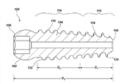
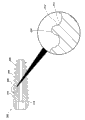
Fig. 1 is the side view according to the surgical screw of embodiments of the invention;
Fig. 2 is the cross sectional side view of the surgical screw shown in Fig. 1;
Fig. 3 is the axonometric chart of the surgical screw shown in Fig. 1;
Fig. 4 is the axonometric chart of the surgical screw shown in Fig. 1;
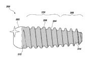
Fig. 5 is the side view according to the surgical screw of embodiments of the invention;
Fig. 6 is the cross sectional side view of the surgical screw shown in Fig. 5;
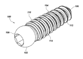
Fig. 7 is the axonometric chart according to the surgical screw of embodiments of the invention;
Fig. 8 is the axonometric chart of the surgical screw shown in Fig. 7;
Fig. 9 is the side view of the surgical screw shown in Fig. 7;
Figure 10 is the cross sectional side view of the surgical screw shown in Fig. 7;
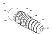
Figure 11 is the side view according to the surgical screw of embodiments of the invention;
Figure 12 is the side view according to the surgical screw of embodiments of the invention; And
Figure 13 and Figure 14 have described the method on bone that flexible member is anchored to according to embodiments of the invention.
The specific embodiment
In order to promote the understanding according to principle of the present invention, referring now to the embodiment shown in the accompanying drawings, and will these embodiment be described with language-specific.But understanding is not intended to scope of the present invention is had to any restriction thus.Any other application of any change that has the feature of the present invention shown in this article that those skilled in the art can expect conventionally of association area and further change and principle of the present invention as shown here is considered in the scope of the present invention for required protection.
It must be noted that, when using in this description and claims, singulative " ", " one " and " described " comprise that plural number refers to thing, unless context is clearly designated as other situation.
When describing the present invention and requiring scope of the present invention, will use following term according to the definition below stated.
When using in this article, term " comprises ", " comprising ", " containing ", " being characterised in that " and grammer equivalent thereof are comprising property or open-ended term, and it does not get rid of other element or the method step do not recorded.
Applicant has found a kind of improved surgical screw or interface device, it makes screw thread minimum to the damage of flexible member, reduce the risk that flexible member is pulled out, and allowed more easily to remove screw when needing in the future, and can further not damage surrounding tissue or bone.Applicant's surgical screw can comprise the screw thread of dual function.For example, the screw thread of applicant's surgical screw can have the form factor changing along screw length.Near the screw thread of screw far-end, can there is sharp-pointed line of cut, for improvement of engaging of the sidewall in the hole with bone, and can there is " level and smooth " line of cut towards the screw thread of near-end, to reduce the damage to graft.
Applicant's surgical screw can also comprise main thread and deputy thread group.Deputy thread group can be configured on main thread, and along with main thread is curling around the axle of surgical screw, deputy thread group is followed main thread.The height of main thread or amplitude can be greater than height or the amplitude of deputy thread group significantly.Main thread and deputy thread group group can be coextensive along the axle of surgical screw.
Applicant's surgical screw can operate to reduce the risk that fixing flexible member is pulled out from bone, and surgical screw remains fixed in hole simultaneously.Applicant's surgical screw can further reduce the generation of skidding between flexible member and surgical screw.Applicant's surgical screw is also designed to avoid screw itself to pull out from bone.Therefore, the surgical screw of recognizing applicant can be increased to the maintenance on flexible member, thereby prevent that flexible member or screw itself from pulling out from bone.
Applicant's surgical screw can comprise the macroshape of zeugopodium, and is included in and when surgical screw is held in place, prevents the microcosmic engagement features that flexible member is pulled out from hole.The character of microcosmic engagement features of the present invention is unique, because it has strengthened the resistance that flexible member is pulled out, and can not damage the ability that surgical screw inserts or extracts out.
With reference now to Fig. 1 to Fig. 4,, described the surgical screw 100 according to embodiments of the invention.In an embodiment of the present invention, as shown in the figure, screw 100 can be cone screw.Screw 100 can comprise screw head 102 and shaft component 104.Screw 100 can extend to far-end 108 from near-end 106.Screw head 102 can be positioned at near-end 106 places.Shaft component 104 itself can extend to from screw head 102 far-end 108 of screw 100.The shaft component 104 of screw 100 can comprise screw thread 110.As now will as described in, the thread tooth of screw thread 110 can, along the length variations of shaft component 104, mean that the shape, path and the physical space that by screw thread 110, are occupied can be along the length variations of shaft component 104.In other words, the size of screw thread 110, thickness, shape, spacing can change or change with any suitable physics mode.
May be as shown in Fig. 2 the best, but also can find out in other figure, the surface topography of screw thread 110 or thread tooth change along the shaft component 104 of screw 100.Especially, the screw thread 110 in the first threaded portion 112 can comprise the line of cut 116 more sharp-pointed than the screw thread 110 in the second threaded portion 114.Screw thread 110 in the second threaded portion 114 can be round than the screw thread 110 in the first threaded portion 112.Screw thread 110 in the second threaded portion 114 can comprise than the screw thread 110 in the first threaded portion 112 and more approaches sinusoidal shape.In an embodiment of the present invention, the screw thread 110 in the first threaded portion 112 can more approach V-arrangement than the screw thread 110 in the second threaded portion 114.
In an embodiment of the present invention, the screw thread 110 in the first threaded portion 112 can have the threaded top 120 more sharp-pointed than the threaded top 122 of the screw thread 110 in the second threaded portion 114.In an embodiment of the present invention, the screw thread 110 in the first threaded portion 112 can be snapped in bone more strongly than the screw thread in second portion 114.In an embodiment of the present invention, the screw thread 110 in the first threaded portion 112 can form higher pressure than the threaded top of the screw thread 110 in second portion 114 122 between threaded top 120 and bone (not shown).In an embodiment of the present invention, the screw thread 110 in the first threaded portion 112 can have the more thread tooth of high pressure, and screw thread 110 in second portion 114 can have the more thread tooth of low-pressure.(more sharp-pointed screw thread focuses on screw power in less region, causes the power of per unit area to cause more greatly and therefore higher pressure).In an embodiment of the present invention, along the thread tooth of the shaft component 104 of screw 100 along its length variations, and along with screw thread 110 is gradually near near-end 106, the sharpness of screw thread 110 reduces.
In an embodiment of the present invention, according to specific embodiment, the length of the first threaded portion 112
d r can be the length D of screw 100
3about 20%-40%, or length
d 1 can be the length D of screw 100
3about 40%-60%.In an embodiment of the present invention, the length D of the second threaded portion 114
2can be the length D of screw 100
3about 50%-70%, or approximately 60%.In an embodiment of the present invention, the screw thread 110 in the second threaded portion 114 can be entirely circle at its place, large footpath, and extends to similar perigon angle in the footpath, the end of screw thread 110.
With reference now to Fig. 5 and Fig. 6,, show the surgical screw 200 according to embodiments of the invention.Screw 200 can have hereinbefore whole, some features in the feature of the screw 100 of describing about Fig. 1-Fig. 4 or not have those features completely.As shown in Figure 5 and Figure 6, screw 200 can comprise head 202 and shaft component 204.Shaft component 204 can comprise screw thread 206.Shaft component 204 can comprise the first threaded portion 208 and the second threaded portion 210.As described above, the screw thread 206 of the first threaded portion 208 can have the line of cut more sharp-pointed than the screw thread of the second threaded portion 210 206.
In an embodiment of the present invention, screw 100 and 200 can form with injection molding process.Screw 100 and 200 can be by PEEK(polyether-ether-ketone) form.
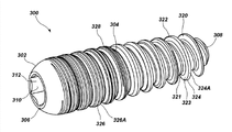
With reference now to Fig. 7-Figure 10,, described surgical screw 300 according to an embodiment of the invention.Screw 300 can comprise screw head 302 and shaft component 304.Screw 300 can extend to far-end 308 from near-end 306.Screw head 302 can be positioned at near-end 306 places.Shaft component 304 can extend to from screw head 302 far-end 308 of screw 300.Can in screw head 302, form recess or recess 310, recess or recess 310 have being configured to and are suitable for receiving the surface 312 of the driving shaft (not shown) of instrument.
Although be the part of same main thread 320, the profile of tooth of the main thread 320 in first 324 and second portion 326 can be different.First 324 and second portion 326 can together with limit the reach of main thread 320.In an embodiment of the present invention, first 326 can extend main thread 320 length about 50% to 70%.In an embodiment of the present invention, second portion 326 can extend main thread 320 length approximately 50% to 70%, and can for example extend approximately 60% of this length.
Also can on the shaft component 304 of screw 300, configure deputy thread group 328.In an embodiment of the present invention, deputy thread group 328 can comprise a kind of situation in single screw thread or a plurality of screw thread.For example, deputy thread group 328 can comprise a screw thread, a double thread, three screw threads, four screw threads or more screw threads.
In an embodiment of the present invention, deputy thread group 328 can be configured on the continuous helical ridge 322 of main thread 320 and follow the continuous helical ridge 322 of main thread 320.In an embodiment of the present invention, deputy thread group 328 can be configured in the peak portion of continuous helical ridge 322 of main thread 320.In an embodiment of the present invention, deputy thread group 328 can exist or not be present in the paddy portion 321 between the curling of main thread 320 or peak portion.
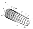
With reference now to Figure 11,, described surgical screw 400 according to an embodiment of the invention.Screw 400 can comprise screw head 402 and shaft component 404.Screw 400 can extend to far-end 408 from near-end 406.Screw head 402 can be positioned at near-end 406 places.Shaft component 404 can extend to from screw head 402 far-end 408 of screw 400.
Also can on the shaft component 404 of screw 400, configure deputy thread group 328.In an embodiment of the present invention, deputy thread group 420 can comprise a kind of situation in single screw thread or a plurality of screw thread.For example, deputy thread group 420 can comprise a screw thread, a double thread, three screw threads or four screw threads.
In an embodiment of the present invention, deputy thread group 420 can be configured on the continuous helical ridge 412 of main thread 410 and follow the continuous helical ridge 412 of main thread 410.In an embodiment of the present invention, deputy thread group 420 can be configured in the peak portion of continuous helical ridge 412 of main thread 320.In an embodiment of the present invention, deputy thread group 420 can not be present in the paddy portion 414 between main thread 410 curling.
In an embodiment of the present invention, deputy thread group 420 can be followed the continuous helical ridge 412 of main thread 410 and the near-end 406 towards surgical screw 400 extends from the far-end 408 of surgical screw 400 above paddy portion 414.In one embodiment, deputy thread group 420 can be coextensive with main thread 410.In one embodiment, deputy thread group 420 can extend beyond along the direction of near-end 406 end of main thread 410.
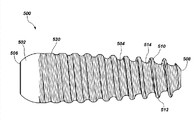
With reference now to Figure 12,, described surgical screw 500 according to an embodiment of the invention.Screw 500 can comprise screw head 502 and shaft component 504.Screw 500 can extend to far-end 508 from near-end 506.Screw head 502 can be positioned at near-end 506 places.Shaft component 504 can extend to from screw head 502 far-end 108 of screw 500.
Also can on the shaft component 504 of screw 500, configure deputy thread group 520.In an embodiment of the present invention, deputy thread group 520 can comprise a kind of situation in single screw thread or a plurality of screw thread.For example, deputy thread group 520 can comprise a screw thread, a double thread, three screw threads or four screw threads.
In an embodiment of the present invention, deputy thread group 520 can along the continuous helical ridge 512 of main thread 510 and in paddy portion 514, from the far-end 508 of surgical screw 500, the near-end 506 towards surgical screw 500 extends.In one embodiment, deputy thread group 520 can be coextensive with main thread 510.In one embodiment, deputy thread group 520 can extend beyond along the direction of near-end 506 end of main thread 510.
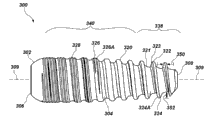
With reference now to Figure 13 and 14,, described to use surgical screw 300 that flexible member 600 is anchored to the process on bone 602.By recognizing, can replace surgical screw 300 and use any in disclosed surgical screw in this article.First, as known in those skilled in the art, can for example with surgical bur, in bone 602, form hole 604.Once form hole 604, just flexible member 600 can be installed in hole 604.
Then can use the instrument 606 of screw 300 rotations that surgical screw 300 is installed, and surgical screw 300 is advanced in hole 604.When first screw 300 advances, sidewall 604 and flexible member 600 that near the main thread 320 far-end 308 can conjugate foramen 604.Along with screw 300 is advanced further, sidewall 608 and flexible member 600 that deputy thread group 328 can conjugate foramen 604.When installing completely, as depicted in figure 14, sidewall 608 and flexible member 600 that main thread 320 and deputy thread group 328 can conjugate foramens 604.
To recognize that main thread 320 and deputy thread group 328 double engagement with the sidewall 608 in hole 604 has improved the ability that screw 300 opposings are pulled out, and allow to remove screw 300 in the situation that further not damaging any tissue or bone.The interpolation of deputy thread 328 allows the maintenance and the screw 300 that in flexible member 600, increase to increase in the maintenance of bone sidewall 608 especially, and there is no improper resistance for removing screw 300 in the future; In brief, screw off simply screw 300 and remove screw 300.Deputy thread group 328 can engage sidewall 608 in the depression being formed by main thread 320.Therefore will recognize to insert moment of torsion and remove moment of torsion not to be subject to too large impact or completely unaffected, because moment of torsion is according to being threadedly engaged with between screw 300 and tissue.; although screw 300 can easily be installed and remove with instrument; but due to the double engagement of main thread and deputy thread, so screw 300 also can provide the resistance of pulling out of enhancing, still allow easily to remove by screwing off simply screw 300 screw 300.Thus, screw 300 has avoided further damaging flexible member 600 or bone 602 during removing.
An example of the means that structure disclosed herein and equipment just prevent that surgical screw from pulling out will be recognized, and should recognize carry out or function that be equal to identical with function disclosed herein for preventing that any structure, equipment or system expection that surgical screw is pulled out from dropping in the scope of the means that prevent that surgical screw from pulling out, and comprises those structures, equipment or the system that surgical screw is pulled out that prevent at present known or that may become available in future.Drop in the scope of this element with preventing any means that means that surgical screw is pulled out play identical or identical functions.
According to feature as described above and combination, a kind of process useful of fixing flexible member comprises the following steps:
(a) drilling bore hole in bone; And
(b) use surgical screw that flexible member is fixed in hole;
Wherein surgical screw comprises head and shaft component, and shaft component has the first threaded portion and the second threaded portion;
Wherein the first threaded portion has the screw thread more sharp-pointed than the screw thread of the second threaded portion.
According to feature as described above and combination, a kind of process useful of fixing flexible member comprises the following steps:
(a) drilling bore hole in bone; And
(b) use surgical screw that flexible member is fixed in hole;
Wherein surgical screw comprises outer surface;
Its outer surface is included in the Micro texture forming on this outer surface.
According to feature as described above and combination, a kind of process useful of fixing flexible member comprises the following steps:
(a) drilling bore hole in bone; And
(b) use surgical screw that flexible member is fixed in hole;
Wherein surgical screw comprises outer surface;
Its outer surface comprises main thread and deputy thread group.
Embodiments of the invention can comprise a kind of surgical screw, have: shaft component, and shaft component has longitudinal axis; The first threaded portion, extends along the first length of shaft component; And second threaded portion, along the second length of shaft component, extend, wherein the first threaded portion has the cut edge more sharp-pointed than the second threaded portion.
Embodiments of the invention can comprise a kind of surgical screw, have: shaft component, and shaft component has longitudinal axis; With the screw thread that the length along shaft component is extended, wherein the surface topography of screw thread or thread tooth are along the length variations of shaft component.
Embodiments of the invention can comprise a kind of surgical screw, have shaft component, and shaft component has longitudinal axis, and wherein said shaft component comprises the screw thread of dual function.
Embodiments of the invention can comprise a kind of surgical screw, have shaft component, and shaft component has longitudinal axis, and wherein said shaft component comprises screw thread, and described screw thread has skimble-scamble thread tooth.
Embodiments of the invention can comprise a kind of surgical screw, have: shaft component, and shaft component has longitudinal axis, and wherein said shaft component comprises the screw thread of variation.
Embodiments of the invention can comprise a kind of surgical screw, have shaft component, and shaft component has longitudinal axis,
Wherein said shaft component comprise far-end and near-end and from far-end the screw thread towards proximal extension, wherein screw thread is more sharp-pointed at the far-end of shaft component.
Embodiments of the invention can comprise a kind of surgical screw, have: shaft component, shaft component has longitudinal axis, wherein said shaft component comprise far-end and near-end and from far-end the screw thread towards proximal extension, wherein thread tooth changes along the shaft component of screw.
Embodiments of the invention can comprise a kind of surgical screw, there is shaft component, shaft component has longitudinal axis, wherein said shaft component comprises far-end and near-end and the screw thread towards proximal extension from far-end, wherein, when the shaft component of screw is arranged in the hole in bone, screw thread forms high pressure and forms lower pressure at near-end at far-end.
Embodiments of the invention can comprise a kind of surgical screw, have shaft component, and shaft component has longitudinal axis, and wherein said shaft component comprises the screw thread that engages hole wall, and have high pressure near the far-end of screw, towards the near-end of screw, have low pressure.
Embodiments of the invention can comprise a kind of surgical screw, have shaft component, and shaft component has longitudinal axis, and wherein said shaft component comprises screw thread.Screw thread can comprise for improvement of the Micro texture engaging with bone and graft.
Embodiments of the invention can comprise a kind of surgical screw, and it has outer surface, and its outer surface is included in the Micro texture forming on this outer surface.
Embodiments of the invention can comprise a kind of surgical screw, and it has outer surface, and its outer surface comprises sawtooth.
Embodiments of the invention can comprise a kind of surgical screw, and it has main thread and deputy thread group, and wherein deputy thread group is configured on main thread.
Embodiments of the invention can comprise a kind of surgical screw, have main thread, and main thread has certain width and amplitude, and wherein along distal-to-proximal direction, width increases and amplitude reduces.
Embodiments of the invention can comprise a kind of surgical screw, have main thread and deputy thread group, and wherein deputy thread group is configured in the peak portion of main thread.
Those of ordinary skill in the related art will recognize by feature of the present invention provides these advantages.For example, the invention is characterized in a kind of surgical screw with two screw threads is provided.Another feature of the present invention is such screw that Micro texture is provided, for preventing that tendon or graft from skidding.According to an aspect of the present invention, another feature of the present invention is to provide a kind of injection moulding surgical screw being formed by PEEK, and it has two thread forms and Micro texture.Of the present invention being further characterized in that provides a kind of surgical screw, and it has main thread and deputy thread group.
In detailed description above, for simplifying object of the present disclosure, various features of the present invention gather together in single embodiment.The method of the present invention should not be construed as and reflects that invention required for protection need to be than the intention of more features of clearly recording in each claim.But as reflected in claim below, aspect of the present invention is fewer than all features of single aforementioned disclosed embodiment.Therefore, claims are quoted and are attached in this specific embodiment by this thus, and wherein each claim represents independent embodiment of the present invention independently.
Should be appreciated that layout as described above is only the illustration of the application of the principles of the present invention.Without departing from the spirit and scope of the present invention, by those skilled in the art, can design many changes and alternative arrangement, and claims are intended to comprise such change and layout.Therefore, although careful and at length shown in the drawings and described hereinbefore the present invention, but will be clearly for those of ordinary skills, in the situation that do not depart from principle and the thought of stating herein, can make many changes, include but not limited to the variation of size, material, shape, form, function and operation, assembling and occupation mode.
Claims (41)
1. for flexible member being anchored to an equipment for bone, described equipment comprises:
Shaft component, has near-end and far-end;
Main thread, is configured on described shaft component and from described far-end towards described proximal extension; And
Be configured in the deputy thread group on described main thread.
2. equipment according to claim 1, wherein said deputy thread group is coextensive with described main thread.
3. equipment according to claim 1, wherein said deputy thread group is extended along the top of described main thread.
4. equipment according to claim 1, wherein said deputy thread group extends beyond described main thread on described proximal direction along described shaft component.
5. equipment according to claim 1, also comprises the head on the described near-end that is configured in described shaft component, and wherein said head comprises composition surface, and the driving shaft of receiving ordinatedly instrument is constructed and be sized to described composition surface.
6. equipment according to claim 1, wherein said main thread has periodically, and described deputy thread group has periodically, and the periodicity of the periodicity of wherein said main thread and described deputy thread group equates substantially.
7. equipment according to claim 1, wherein said main thread comprises around the curling continuous helical ridge of described shaft component, wherein said deputy thread group be configured in described main thread on the continuous helical ridge of described shaft component and follow described continuous helical ridge.
8. equipment according to claim 7, wherein said deputy thread group is also configured between described continuous helical ridge curling.
9. equipment according to claim 1, wherein said main thread comprises first and second portion, described first and described second portion respectively have terminal edges, and the terminal edges of wherein said first is more sharp-pointed than the terminal edges of described second portion.
10. equipment according to claim 9, wherein said deputy thread group only with the described second portion of described main thread with prolonging.
11. equipment according to claim 1, wherein said deputy thread group consists of single screw thread.
12. equipment according to claim 1, wherein said deputy thread group comprises a plurality of screw threads.
13. equipment according to claim 1, are also included in the lip-deep Micro texture of described shaft component.
14. equipment according to claim 1, wherein said main thread comprises that certain thread depth and described deputy thread group comprise certain thread depth, the thread depth of wherein said deputy thread group be less than described main thread height 20%.
15. equipment according to claim 1, wherein said flexible member is tissue.
16. 1 kinds are fixed to the method on bone by flexible member, and described method comprises:
In described bone, form hole,
A part for described flexible member is placed in described hole;
Use interface device that described flexible member is fixed in described hole, wherein said interface device comprises:
Shaft component, has near-end and far-end;
Main thread, is configured on described shaft component and from described far-end towards described proximal extension; And
Be configured in the deputy thread group on described main thread.
17. methods according to claim 16, wherein said deputy thread group is coextensive with described main thread.
18. methods according to claim 16, wherein said deputy thread group is configured in the top of described shaft component.
19. methods according to claim 16, wherein said deputy thread group surpasses described main thread towards the proximal extension of described shaft component.
20. methods according to claim 16, wherein said main thread has periodically and described deputy thread group has periodically, and the periodicity of the periodicity of wherein said main thread and described deputy thread group equates substantially.
21. methods according to claim 16, wherein said main thread comprises around the curling continuous helical ridge of described shaft component, wherein said deputy thread group is configured on the continuous helical ridge of described main thread and follows the described continuous helical ridge of described main thread.
22. methods according to claim 21, wherein said deputy thread group is also configured between described continuous helical ridge curling.
23. methods according to claim 16, wherein said main thread comprises that certain thread depth and described deputy thread group comprise certain thread depth, the thread depth of wherein said deputy thread group be less than described main thread height 20%.
24. 1 kinds for anchoring to flexible member the equipment on bone, and described equipment comprises:
Shaft component extends between near-end and far-end, and described shaft component has surface;
Be configured in the described lip-deep main thread of described axle; And
Described main thread has the first threaded portion and the second threaded portion, and each in described the first threaded portion and described the second threaded portion has terminal edges;
Wherein said the first threaded portion is the proximal extension towards described shaft component from the far-end of described shaft component;
Described the first threaded portion is sequentially followed in wherein said the second threaded portion on described shaft component;
The described terminal edges of wherein said the first threaded portion is more sharp-pointed than the described terminal edges of described the second threaded portion;
Wherein said the first threaded portion the length of described main thread 50% to 70% between extend.
25. equipment according to claim 24, about 60% of the length that the length of wherein said the first threaded portion is described main thread.
26. equipment according to claim 24, are also included in the transition part between described the first threaded portion and described the second threaded portion, and wherein said transition part is sharply.
27. equipment according to claim 24, also comprise with described far-end and are relatively configured in the head on described shaft component, wherein said head comprises composition surface, and described composition surface is constructed and is sized to and receives ordinatedly drive member.
28. equipment according to claim 24, wherein said main thread comprises around the curling continuous helical ridge of described shaft component.
29. 1 kinds for anchoring to flexible member the equipment of bone, and described equipment comprises:
Shaft component extends between near-end and far-end, and described shaft component has surface;
Be configured in the described lip-deep main thread of described axle; And
Described main thread has certain width of thread and certain screw thread amplitude;
Wherein, along distal-to-proximal direction, the described width of thread increases and described screw thread amplitude reduces.
30. equipment according to claim 29, also comprise with described near-end and are adjacent to be configured in the head on described shaft component,
Wherein said head comprises composition surface, and described composition surface is constructed and is sized to and receives ordinatedly drive member.
31. equipment according to claim 29, wherein said main thread comprises around the curling continuous helical ridge of described shaft component.
32. equipment according to claim 29, wherein said main thread comprises the first adjacent with the far-end of described shaft component and the second portion of following described first, described first has the edge more sharp-pointed than the edge of described second portion.
33. 1 kinds for anchoring to flexible member the equipment of bone, and described equipment comprises:
Shaft component extends between near-end and far-end, and described shaft component has surface;
Be configured in the described lip-deep main thread of described axle, described main thread comprises that described ridge has peak portion around the curling continuous helical ridge of described shaft component; And
Be configured in the deputy thread group in the peak portion of ridge of described main thread.
34. equipment according to claim 33, also comprise with described near-end and are adjacent to be configured in the head on described shaft component, wherein said head comprises composition surface, and described composition surface is constructed and is sized to and receives ordinatedly drive member.
35. equipment according to claim 33, wherein said main thread comprises the first adjacent with the far-end of described shaft component and the second portion of following described first, described first has the edge more sharp-pointed than the edge of described second portion.
36. equipment according to claim 33, wherein said flexible member is ligament.
37. equipment according to claim 33, wherein said deputy thread group consists of single screw thread.
38. equipment according to claim 33, wherein said deputy thread group comprises at least two screw threads.
39. equipment according to claim 33, wherein said deputy thread group exists only in the peak portion of ridge of described main thread, and is not present on any sidewall or paddy portion of described main thread.
40. equipment according to claim 33, the quantity of the deputy thread of each peak portion of the ridge of wherein said main thread increases along distal-to-proximal direction.
41. 1 kinds for anchoring to flexible member the equipment of bone, and described equipment comprises:
Shaft component, has near-end and far-end;
Main thread, is configured on described shaft component and from described far-end towards described proximal extension; And
Be configured in the deputy thread group on described main thread;
Be configured in the head on the described near-end of described shaft component, wherein said head comprises composition surface, described composition surface structure and be sized to the driving shaft of receiving ordinatedly instrument;
Wherein said deputy thread group is extended along the top of described main thread;
Wherein said deputy thread group extends beyond described main thread on described proximal direction along described shaft component;
Wherein said main thread has periodically and described deputy thread group has periodically, and the periodicity of the periodicity of wherein said main thread and described deputy thread group equates substantially;
Wherein said main thread comprises around the curling continuous helical ridge of described shaft component, wherein said deputy thread group be configured in described main thread on the continuous helical ridge of described shaft component and follow described continuous helical ridge;
Wherein said deputy thread group is also configured between described continuous helical ridge curling;
Wherein said main thread comprises first and second portion, and described first and described second portion respectively have terminal edges, and the terminal edges of wherein said first is more sharp-pointed than the terminal edges of described second portion;
Wherein said deputy thread group comprises a plurality of screw threads;
Wherein said main thread comprises that certain thread depth and described deputy thread group comprise certain thread depth, the thread depth of wherein said deputy thread group be less than described main thread height 20%.
Applications Claiming Priority (5)
| Application Number | Priority Date | Filing Date | Title |
|---|---|---|---|
| US42356610P | 2010-12-15 | 2010-12-15 | |
| US61/423,566 | 2010-12-15 | ||
| US13/327,727 US20120158137A1 (en) | 2010-12-15 | 2011-12-15 | Peek-rich bone screw |
| US13/327,727 | 2011-12-15 | ||
| PCT/IB2011/003279 WO2012080846A2 (en) | 2010-12-15 | 2011-12-15 | Peek-rich bone screw |
Publications (1)
| Publication Number | Publication Date |
|---|---|
| CN103648422A true CN103648422A (en) | 2014-03-19 |
Family
ID=46235398
Family Applications (1)
| Application Number | Title | Priority Date | Filing Date |
|---|---|---|---|
| CN201180067614.6A Pending CN103648422A (en) | 2010-12-15 | 2011-12-15 | Peek-rich bone screw |
Country Status (10)
| Country | Link |
|---|---|
| US (1) | US20120158137A1 (en) |
| EP (1) | EP2651322A2 (en) |
| JP (2) | JP6334168B2 (en) |
| CN (1) | CN103648422A (en) |
| AU (2) | AU2011342906B2 (en) |
| BR (1) | BR112013015210B1 (en) |
| MX (1) | MX2013006872A (en) |
| RU (1) | RU2600284C2 (en) |
| WO (1) | WO2012080846A2 (en) |
| ZA (1) | ZA201304230B (en) |
Cited By (7)
| Publication number | Priority date | Publication date | Assignee | Title |
|---|---|---|---|---|
| CN104173095A (en) * | 2014-09-15 | 2014-12-03 | 广东泓志生物科技有限公司 | Interference screw for department of orthopaedics |
| CN104840243A (en) * | 2015-06-02 | 2015-08-19 | 北京纳通科技集团有限公司 | Spine screw |
| CN106473836A (en) * | 2016-12-12 | 2017-03-08 | 运怡(北京)医疗器械有限公司 | A kind of porous PEEK interface nail |
| CN106999217A (en) * | 2014-11-04 | 2017-08-01 | 海普瑞万迅公司 | Implant for consolidating knochenbruch or non-knochenbruch |
| CN107280756A (en) * | 2017-07-21 | 2017-10-24 | 西安康拓医疗技术有限公司 | A kind of medical cranial Bone nail structure |
| CN111194188A (en) * | 2017-10-09 | 2020-05-22 | 康曼德公司 | Easy-to-start hollow bone screw |
| US10959830B2 (en) | 2016-01-07 | 2021-03-30 | Innovate Orthopaedics Limited | Fixation device |
Families Citing this family (15)
| Publication number | Priority date | Publication date | Assignee | Title |
|---|---|---|---|---|
| EP3323388B1 (en) | 2012-08-24 | 2019-09-18 | Cook Medical Technologies LLC | Medical device for the medialization of a vocal cord |
| US9433499B2 (en) | 2013-05-07 | 2016-09-06 | Cook Medical Technologies Llc | Vocal cord medialization |
| USD812751S1 (en) | 2016-02-03 | 2018-03-13 | Karl Storz Gmbh & Co. Kg | Interference bone screw |
| USD846977S1 (en) * | 2016-05-12 | 2019-04-30 | Innovate Orthopaedics Limited | Screw |
| US11389205B2 (en) * | 2016-11-30 | 2022-07-19 | Stryker European Operations Holdings Llc | Spinal fastener with serrated thread |
| USD834192S1 (en) * | 2017-04-20 | 2018-11-20 | Paul Y. Lee | Pin for medical applications |
| USD898196S1 (en) | 2017-07-10 | 2020-10-06 | Stryker European Holdings I, Llc | Spinal fastener with serrated thread |
| USD835787S1 (en) * | 2017-08-04 | 2018-12-11 | Therapeutic Recreation Systems, Inc. | Helix prosthesis |
| USD868967S1 (en) * | 2017-10-13 | 2019-12-03 | Karl Storz Se & Co. Kg | Interference screw |
| USD921898S1 (en) * | 2017-12-22 | 2021-06-08 | Orthocision Inc. | Helical implant |
| RU2696963C1 (en) * | 2018-04-04 | 2019-08-07 | федеральное государственное бюджетное образовательное учреждение высшего образования "Саратовский государственный медицинский университет имени В.И. Разумовского" Министерства здравоохранения Российской Федерации (ФГБОУ ВО Саратовский ГМУ им. В.И. Разумовского Минздрава России) | Device for fixing graft with plastic anterior cruciate ligament |
| RU182229U1 (en) * | 2018-04-04 | 2018-08-08 | федеральное государственное бюджетное образовательное учреждение высшего образования "Саратовский государственный медицинский университет имени В.И. Разумовского" Министерства здравоохранения Российской Федерации (ФГБОУ ВО Саратовский ГМУ им. В.И. Разумовского Минздрава России) | Anterior cruciate ligament transplant fixator |
| KR20210064236A (en) * | 2018-09-26 | 2021-06-02 | 스피닉스, 인크. | Extendable and adjustable trunk fusion system for lordosis of the spine |
| USD938592S1 (en) * | 2019-06-20 | 2021-12-14 | Signum Surgical Limited | Implant |
| CN114294311B (en) * | 2021-12-30 | 2022-09-16 | 中南大学 | Anti-pulling flexible shear-resistant self-tapping screw |
Citations (7)
| Publication number | Priority date | Publication date | Assignee | Title |
|---|---|---|---|---|
| US5456685A (en) * | 1994-02-14 | 1995-10-10 | Smith & Nephew Dyonics, Inc. | Interference screw having a tapered back root |
| WO2000047120A1 (en) * | 1999-02-10 | 2000-08-17 | Depuy Acromed, Inc. | Bi-fed offset pitch bone screw |
| US6743233B1 (en) * | 2000-08-02 | 2004-06-01 | Orthopaedic Biosystems, Ltd., Inc. | Medical screw and method of installation |
| WO2007107995A1 (en) * | 2006-03-21 | 2007-09-27 | Uri Arni | Dental implant |
| CN101394802A (en) * | 2006-02-16 | 2009-03-25 | 华沙整形外科股份有限公司 | Multi-thread bone screw |
| US20090171401A1 (en) * | 2007-12-31 | 2009-07-02 | Thomas Zehnder | Pedicle screw with a closure device for securing a rod for stabilization of the vertebral column |
| CN201551386U (en) * | 2009-11-26 | 2010-08-18 | 中国科学院上海硅酸盐研究所 | antimicrobial bone fixing screw |
Family Cites Families (18)
| Publication number | Priority date | Publication date | Assignee | Title |
|---|---|---|---|---|
| US4103422A (en) * | 1975-03-07 | 1978-08-01 | Oratronics, Inc. | Threaded self-tapping endodontic stabilizer |
| JPS59122413U (en) * | 1983-02-05 | 1984-08-17 | 三笠産業株式会社 | taper screw |
| JPH06304186A (en) * | 1993-04-21 | 1994-11-01 | Nikon Corp | Intraosseous implant |
| EP1093774B1 (en) * | 1999-10-21 | 2002-06-19 | Karl Storz GmbH & Co. KG | Interference screw |
| US6635059B2 (en) * | 2001-01-03 | 2003-10-21 | Bernard L. Randall | Cannulated locking screw system especially for transiliac implant |
| JP3078986U (en) * | 2001-01-18 | 2001-07-27 | 銓春螺絲股▲ふん▼有限公司 | Screw structure |
| SE518461C2 (en) * | 2001-02-21 | 2002-10-15 | Henrik Hansson | Bone screw, way to make its threads and drill to drill holes for same |
| US6620195B2 (en) * | 2001-04-18 | 2003-09-16 | Medicinelodge, Inc. | Apparatus and method for attaching a graft ligament to a bone |
| JP3081944U (en) * | 2001-05-21 | 2001-11-22 | 美華 黄 | Wood screw |
| RU2204963C1 (en) * | 2001-11-01 | 2003-05-27 | Московский областной научно-исследовательский клинический институт | Fixing member for attaching transplant to femur condyle in performing plastic repair of anterior cruciate ligament |
| US7066937B2 (en) * | 2002-02-13 | 2006-06-27 | Endius Incorporated | Apparatus for connecting a longitudinal member to a bone portion |
| WO2004098442A1 (en) * | 2003-05-03 | 2004-11-18 | Wolfgang Dinkelacker | Bone implant that can be screwed in |
| US7766915B2 (en) * | 2004-02-27 | 2010-08-03 | Jackson Roger P | Dynamic fixation assemblies with inner core and outer coil-like member |
| CN103479419B (en) * | 2005-04-08 | 2017-04-12 | 帕拉迪格脊骨有限责任公司 | Interspinous vertebral and lumbosacral stabilization devices and methods of use |
| DE112006000003B4 (en) * | 2006-01-27 | 2008-09-25 | Osstem Co., Ltd. | fastening device |
| WO2008121928A2 (en) * | 2007-03-31 | 2008-10-09 | 3M Imtec Corporation | Implant thread design |
| US8128671B2 (en) * | 2007-04-04 | 2012-03-06 | Warsaw Orthopedic, Inc. | Variable flank bone screw |
| EP2160988B1 (en) * | 2008-09-04 | 2012-12-26 | Biedermann Technologies GmbH & Co. KG | Rod-shaped implant in particular for stabilizing the spinal column and stabilization device including such a rod-shaped implant |
-
2011
- 2011-12-15 WO PCT/IB2011/003279 patent/WO2012080846A2/en active Application Filing
- 2011-12-15 MX MX2013006872A patent/MX2013006872A/en not_active Application Discontinuation
- 2011-12-15 AU AU2011342906A patent/AU2011342906B2/en active Active
- 2011-12-15 JP JP2013543906A patent/JP6334168B2/en active Active
- 2011-12-15 RU RU2013130919/14A patent/RU2600284C2/en active
- 2011-12-15 EP EP11847995.5A patent/EP2651322A2/en not_active Withdrawn
- 2011-12-15 US US13/327,727 patent/US20120158137A1/en not_active Abandoned
- 2011-12-15 CN CN201180067614.6A patent/CN103648422A/en active Pending
- 2011-12-15 BR BR112013015210-9A patent/BR112013015210B1/en active IP Right Grant
-
2013
- 2013-06-10 ZA ZA2013/04230A patent/ZA201304230B/en unknown
-
2016
- 2016-02-16 AU AU2016200985A patent/AU2016200985A1/en not_active Abandoned
- 2016-08-04 JP JP2016153603A patent/JP2016190079A/en active Pending
Patent Citations (7)
| Publication number | Priority date | Publication date | Assignee | Title |
|---|---|---|---|---|
| US5456685A (en) * | 1994-02-14 | 1995-10-10 | Smith & Nephew Dyonics, Inc. | Interference screw having a tapered back root |
| WO2000047120A1 (en) * | 1999-02-10 | 2000-08-17 | Depuy Acromed, Inc. | Bi-fed offset pitch bone screw |
| US6743233B1 (en) * | 2000-08-02 | 2004-06-01 | Orthopaedic Biosystems, Ltd., Inc. | Medical screw and method of installation |
| CN101394802A (en) * | 2006-02-16 | 2009-03-25 | 华沙整形外科股份有限公司 | Multi-thread bone screw |
| WO2007107995A1 (en) * | 2006-03-21 | 2007-09-27 | Uri Arni | Dental implant |
| US20090171401A1 (en) * | 2007-12-31 | 2009-07-02 | Thomas Zehnder | Pedicle screw with a closure device for securing a rod for stabilization of the vertebral column |
| CN201551386U (en) * | 2009-11-26 | 2010-08-18 | 中国科学院上海硅酸盐研究所 | antimicrobial bone fixing screw |
Cited By (9)
| Publication number | Priority date | Publication date | Assignee | Title |
|---|---|---|---|---|
| CN104173095A (en) * | 2014-09-15 | 2014-12-03 | 广东泓志生物科技有限公司 | Interference screw for department of orthopaedics |
| CN104173095B (en) * | 2014-09-15 | 2016-05-04 | 广东泓志生物科技有限公司 | A kind of orthopaedics extrusion screw |
| CN106999217A (en) * | 2014-11-04 | 2017-08-01 | 海普瑞万迅公司 | Implant for consolidating knochenbruch or non-knochenbruch |
| CN106999217B (en) * | 2014-11-04 | 2021-04-13 | 海普瑞万迅公司 | Implant for stabilizing fractured or non-fractured bones |
| CN104840243A (en) * | 2015-06-02 | 2015-08-19 | 北京纳通科技集团有限公司 | Spine screw |
| US10959830B2 (en) | 2016-01-07 | 2021-03-30 | Innovate Orthopaedics Limited | Fixation device |
| CN106473836A (en) * | 2016-12-12 | 2017-03-08 | 运怡(北京)医疗器械有限公司 | A kind of porous PEEK interface nail |
| CN107280756A (en) * | 2017-07-21 | 2017-10-24 | 西安康拓医疗技术有限公司 | A kind of medical cranial Bone nail structure |
| CN111194188A (en) * | 2017-10-09 | 2020-05-22 | 康曼德公司 | Easy-to-start hollow bone screw |
Also Published As
| Publication number | Publication date |
|---|---|
| WO2012080846A3 (en) | 2012-08-23 |
| ZA201304230B (en) | 2014-02-26 |
| RU2013130919A (en) | 2015-01-20 |
| AU2016200985A1 (en) | 2016-03-03 |
| MX2013006872A (en) | 2013-11-22 |
| AU2011342906A1 (en) | 2013-07-11 |
| JP2014508550A (en) | 2014-04-10 |
| EP2651322A2 (en) | 2013-10-23 |
| JP6334168B2 (en) | 2018-05-30 |
| RU2600284C2 (en) | 2016-10-20 |
| WO2012080846A2 (en) | 2012-06-21 |
| BR112013015210A2 (en) | 2016-09-13 |
| US20120158137A1 (en) | 2012-06-21 |
| JP2016190079A (en) | 2016-11-10 |
| BR112013015210B1 (en) | 2020-12-15 |
| AU2011342906B2 (en) | 2016-03-03 |
Similar Documents
| Publication | Publication Date | Title |
|---|---|---|
| CN103648422A (en) | Peek-rich bone screw | |
| EP2647349B1 (en) | Fixture for a dental implant | |
| US20070053765A1 (en) | Thread on a bone screw | |
| US6685728B2 (en) | Threaded suture anchor and method of use | |
| EP1749490B1 (en) | Bone anchoring element | |
| US20040243129A1 (en) | Double helical threaded bone screw | |
| US8764797B2 (en) | Suture anchor with insert-molded suture eyelet | |
| US6402515B1 (en) | Dental implant with variable profile thread | |
| EP2361574B1 (en) | Bone screw | |
| US9855119B2 (en) | Dental implant fixture | |
| AU2002367551A1 (en) | Threaded suture anchor and method of use | |
| WO2004084704A3 (en) | Apparatus for implantation into bone | |
| US20130216976A1 (en) | Self-tapping screw implant | |
| CN1980611A (en) | Double lead bone screw | |
| JP2006528895A (en) | Soft tissue screw | |
| JP2016508848A (en) | Micro anchor | |
| EP3533398B1 (en) | Bone anchor having improved fixation strength | |
| CN103379877A (en) | Implant fixture | |
| KR200454191Y1 (en) | Implant fixture | |
| CN103974669A (en) | Self-holding feature for a screw | |
| CA2567407C (en) | Threaded suture anchor and method of use |
Legal Events
| Date | Code | Title | Description |
|---|---|---|---|
| PB01 | Publication | ||
| PB01 | Publication | ||
| C10 | Entry into substantive examination | ||
| SE01 | Entry into force of request for substantive examination | ||
| RJ01 | Rejection of invention patent application after publication | ||
| RJ01 | Rejection of invention patent application after publication |
Application publication date: 20140319 |