CN1043201C - Occupant restraint system actuated by a simple operation using a feature value - Google Patents
Occupant restraint system actuated by a simple operation using a feature value Download PDFInfo
- Publication number
- CN1043201C CN1043201C CN95117640A CN95117640A CN1043201C CN 1043201 C CN1043201 C CN 1043201C CN 95117640 A CN95117640 A CN 95117640A CN 95117640 A CN95117640 A CN 95117640A CN 1043201 C CN1043201 C CN 1043201C
- Authority
- CN
- China
- Prior art keywords
- mentioned
- value
- external force
- vector
- vehicle
- Prior art date
- Legal status (The legal status is an assumption and is not a legal conclusion. Google has not performed a legal analysis and makes no representation as to the accuracy of the status listed.)
- Expired - Fee Related
Links
- 230000001133 acceleration Effects 0.000 claims abstract description 49
- 230000009471 action Effects 0.000 claims description 19
- 230000010354 integration Effects 0.000 claims description 9
- 238000000605 extraction Methods 0.000 claims description 5
- 238000004364 calculation method Methods 0.000 abstract description 6
- 230000000452 restraining effect Effects 0.000 abstract 2
- 230000002194 synthesizing effect Effects 0.000 abstract 1
- 238000010586 diagram Methods 0.000 description 29
- 238000000034 method Methods 0.000 description 12
- 230000008569 process Effects 0.000 description 6
- 230000008859 change Effects 0.000 description 5
- 238000001514 detection method Methods 0.000 description 3
- 230000036316 preload Effects 0.000 description 3
- 238000006073 displacement reaction Methods 0.000 description 2
- 230000003252 repetitive effect Effects 0.000 description 2
- 230000008901 benefit Effects 0.000 description 1
- 238000004422 calculation algorithm Methods 0.000 description 1
- 238000006243 chemical reaction Methods 0.000 description 1
- 230000000052 comparative effect Effects 0.000 description 1
- 230000034994 death Effects 0.000 description 1
- 231100000517 death Toxicity 0.000 description 1
- 230000000694 effects Effects 0.000 description 1
- 238000005516 engineering process Methods 0.000 description 1
- 238000002474 experimental method Methods 0.000 description 1
- 238000001914 filtration Methods 0.000 description 1
- 230000010355 oscillation Effects 0.000 description 1
- 230000001681 protective effect Effects 0.000 description 1
- 238000007634 remodeling Methods 0.000 description 1
- 238000004088 simulation Methods 0.000 description 1
- 230000006641 stabilisation Effects 0.000 description 1
- 238000011105 stabilization Methods 0.000 description 1
- 230000009897 systematic effect Effects 0.000 description 1
- 210000003813 thumb Anatomy 0.000 description 1
- 230000009466 transformation Effects 0.000 description 1
Images


Classifications
-
- B—PERFORMING OPERATIONS; TRANSPORTING
- B60—VEHICLES IN GENERAL
- B60R—VEHICLES, VEHICLE FITTINGS, OR VEHICLE PARTS, NOT OTHERWISE PROVIDED FOR
- B60R21/00—Arrangements or fittings on vehicles for protecting or preventing injuries to occupants or pedestrians in case of accidents or other traffic risks
- B60R21/02—Occupant safety arrangements or fittings, e.g. crash pads
- B60R21/16—Inflatable occupant restraints or confinements designed to inflate upon impact or impending impact, e.g. air bags
-
- B—PERFORMING OPERATIONS; TRANSPORTING
- B60—VEHICLES IN GENERAL
- B60R—VEHICLES, VEHICLE FITTINGS, OR VEHICLE PARTS, NOT OTHERWISE PROVIDED FOR
- B60R21/00—Arrangements or fittings on vehicles for protecting or preventing injuries to occupants or pedestrians in case of accidents or other traffic risks
- B60R21/01—Electrical circuits for triggering passive safety arrangements, e.g. airbags, safety belt tighteners, in case of vehicle accidents or impending vehicle accidents
- B60R21/013—Electrical circuits for triggering passive safety arrangements, e.g. airbags, safety belt tighteners, in case of vehicle accidents or impending vehicle accidents including means for detecting collisions, impending collisions or roll-over
- B60R21/0132—Electrical circuits for triggering passive safety arrangements, e.g. airbags, safety belt tighteners, in case of vehicle accidents or impending vehicle accidents including means for detecting collisions, impending collisions or roll-over responsive to vehicle motion parameters, e.g. to vehicle longitudinal or transversal deceleration or speed value
- B60R21/01332—Electrical circuits for triggering passive safety arrangements, e.g. airbags, safety belt tighteners, in case of vehicle accidents or impending vehicle accidents including means for detecting collisions, impending collisions or roll-over responsive to vehicle motion parameters, e.g. to vehicle longitudinal or transversal deceleration or speed value by frequency or waveform analysis
- B60R21/01338—Electrical circuits for triggering passive safety arrangements, e.g. airbags, safety belt tighteners, in case of vehicle accidents or impending vehicle accidents including means for detecting collisions, impending collisions or roll-over responsive to vehicle motion parameters, e.g. to vehicle longitudinal or transversal deceleration or speed value by frequency or waveform analysis using vector analysis
-
- B—PERFORMING OPERATIONS; TRANSPORTING
- B60—VEHICLES IN GENERAL
- B60R—VEHICLES, VEHICLE FITTINGS, OR VEHICLE PARTS, NOT OTHERWISE PROVIDED FOR
- B60R21/00—Arrangements or fittings on vehicles for protecting or preventing injuries to occupants or pedestrians in case of accidents or other traffic risks
- B60R21/01—Electrical circuits for triggering passive safety arrangements, e.g. airbags, safety belt tighteners, in case of vehicle accidents or impending vehicle accidents
- B60R21/013—Electrical circuits for triggering passive safety arrangements, e.g. airbags, safety belt tighteners, in case of vehicle accidents or impending vehicle accidents including means for detecting collisions, impending collisions or roll-over
- B60R21/0132—Electrical circuits for triggering passive safety arrangements, e.g. airbags, safety belt tighteners, in case of vehicle accidents or impending vehicle accidents including means for detecting collisions, impending collisions or roll-over responsive to vehicle motion parameters, e.g. to vehicle longitudinal or transversal deceleration or speed value
Abstract
An occupant restraint system is disclosed in which a determination on the actuation of the system is made by a simple calculation. A first feature value is extracted from a first component of acceleration caused by an external force exerted on a vehicle (12) in a first direction, the first feature value representing a first vector of the external force with respect to the first direction. A second feature value is extracted from a second component of the acceleration in a second direction, the second feature value representing a second vector of the external force with respect to the second direction. A magnitude and a direction of a synthesized vector is obtained by synthesizing the first vector and the second vector. A projective magnitude of a projective vector is obtained from the synthesized vector, the projective vector being a vector which is a projection of the synthesized vector with respect to a predetermined direction. Actuation of the restraining means is determined by comparing the projective magnitude with a predetermined threshold value so that the restraining means is actuated when the projective magnitude is greater than the predetermined threshold value.
Description
The present invention relates generally to the occupant restraint system of vehicle, when the acceleration/accel that especially relates to vehicle surpasses predetermined value, occupant's occupant restraint system in the protection vehicle.
The occupant restraint system that vehicle uses, as airbag or safety strap preload device, in engineering technology, well-known.When the acceleration/accel of vehicle surpasses predetermined value, start this system, with occupant's restriction, lean against on its seat.During the occupant restraint system action, the occupant keeps in place.
Only when the occupant really needed protection, occupant restraint system just should start as airbag.When the occupant can not keep its position voluntarily, the situation that the occupant must be protected just can occur.Huge external force acts on the vehicle of travel direction this situation can occur.
In addition, from vehicular sideview sizable power takes place, promptly vehicle laterally (about) produce sizable acceleration/accel, the occupant must be subjected to protection.At this moment, vertical (front and back) of vehicle can not produce tangible acceleration/accel.
So, for the correct action of measuring occupant restraint system.Must consider acceleration/accel that vertically produces and the acceleration/accel that laterally produces.
This occupant restraint system slope is exposed at Japanese Laid-Open Patent Application 6-56000.Acceleration/accel back/forth component GX and left and right sides component GY with this systematic survey vehicle generation.Two kinds of components are synthetic to draw resultant vector, and calculates the value F and the direction θ of resultant vector.Direction θ draws threshold value Fth (θ) then.Determine again value F whether greater than with the corresponding threshold value Fth θ of direction θ (F>Fth (θ)).When above-mentioned condition satisfies, airbag system start-up.In this system, the startup of airbag system is determined by the size of force direction and power according to vehicle.Like this, just can determine suitably the action, and with the stressed orientation independent of vehicle.
Whenever vehicle is subjected to external force, above-mentioned traditional occupant restraint system must calculated direction θ and with the corresponding threshold value Fth of direction θ (θ).In order to obtain threshold value Fth (θ), release an equation, so that carry out complicated calculating.That is to say that before system acting was determined, there were the many problems that must carry out computing in this system.From this point, above-mentioned traditional occupant restraint system is actual can not be used.
General objects of the present invention is to eliminate the problems referred to above for vehicle, and a kind of useful occupant restraint system of remodeling is provided.
Special purpose of the present invention provides a kind of by simple operation, determines the occupant restraint system of system acting.
In order to achieve the above object, propose a kind of vehicle occupant protection system of one aspect of the invention, as the principle of the invention that Fig. 1 describes, when vehicle was subjected to external force, vehicle produced acceleration/accel, and this occupant restraint system comprises:
Fender guard (M
5), the occupant of above-mentioned vehicle when being used for protecting external force to surpass predetermined value;
External force supposition device (M
1, M
2, M
3), be used to suppose the size and Orientation of the suffered external force of vehicle;
Projection value computer device (M
4), being used to calculate the projection vector projection value that draws with the corresponding outer force vector of external force, outer force vector is obtained by the value and the direction of the supposition of external force supposition device, and projection vector is the outer force vector projection with respect to predetermined direction; And
Device (M is determined in action
6), be used for determining the starting of fender guard, by the comparison of projection value and predetermined threshold, make that at projection value fender guard moves during greater than predetermined threshold.
External force supposition device comprises:
The first characteristic value extraction element (M
1), being used to extract first characteristic value of first direction acceleration/accel first component, the representative of first characteristic value is with respect to external force first vector of first direction;
The second characteristic value extraction element (M
2), being used to extract second characteristic value of the second direction acceleration/accel second component that is different from first direction, the representative of second characteristic value is with respect to above-mentioned external force second vector of second direction; And
Resultant vector computer device (M
3), being used to calculate the direction and the size of resultant vector, resultant vector is drawn by first vectorial sum, second vector resultant, and corresponding with outer force vector.
In foregoing invention, be subjected to acceleration that external force causes corresponding to vector component with respect to the predetermined direction vehicle, its size is represented the projection value of resultant vector, this value is easy to obtain, and simply calculates and can accomplish according to the resultant vector size and Orientation that utilizes first characteristic value and second characteristic value to calculate.Owing to compare by projection value and predetermined threshold, measure the action of fender guard very simply, so, can accomplish accurately to determine with simple calculating.
In foregoing invention, projection value computer device (M
4) can calculate the projection value of many predetermined directions, device (M is determined in action
6) relatively each projection value and the definite threshold value of all directions accordingly, when projection value surpasses the respective threshold of arbitrary predetermined direction, promptly determine starting guard equipment (M
5).If suffered external force direction of vehicle and fore-and-aft direction oblique, then vehicle produces rotational force.Produce the poor of acceleration/accel starting stage between the left and right vehicle wheel side like this.That is to say that wherein the acceleration/accel of a side starting stage is relatively greater than the acceleration/accel of opposite side.Because when the shadow value surpassed the corresponding threshold value of arbitrary predetermined direction, device (M was determined in action
6) starting guard equipment (M
5), so can in very short time, make definite.
In addition, according to the present invention on the other hand, as the principle of the invention that Fig. 2 describes, release a kind of vehicle occupant protection system, when vehicle was subjected to external force, vehicle produced acceleration/accel, and this occupant restraint system comprises:
Protective position (M
5), the occupant of vehicle when being used for protecting external force to surpass predetermined value;
The first characteristic value extraction element (M
7), be used to extract first characteristic value of vehicle fore-and-aft direction acceleration/accel first component;
Second characteristic value must be got device (M
9), be used to extract second characteristic value of left and right vehicle wheel directional acceleration second component;
Device (M is determined in action
8), be used to determine starting at first characteristic value fender guard during greater than predetermined threshold; And
Threshold transformation device (M
10), being used for predetermined threshold being become suitable value according to second characteristic value, threshold value is along with the absolute value of second characteristic value increases and reduces.
According to the present invention,, can determine fender guard (M by the simple comparison of first characteristic value and predetermined threshold
5) action.Do not need to calculate the threshold value or the resultant vector of single direction like this.Thereby, by simple calculations, can accomplish accurately to determine, and not carry out complicated calculating.
By following detailed description, conjunction with figs. is read, other purposes of the present invention, and feature and advantage are more obvious.
Fig. 1 is a diagram of block, the occupant restraint system principle of expression one aspect of the invention;
Fig. 2 is a diagram of block, the occupant restraint system principle of another aspect of expression the present invention;
Fig. 3 is the occupant restraint system diagram of block of first embodiment of the invention;
Fig. 4 is a total system structure illustration shown in Figure 3;
The diagram of circuit that Fig. 5 handles for CPU shown in Figure 3;
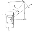
Fig. 6 is a characteristic value method of calculating illustration;
Fig. 7 asks the algorithm illustration for the predetermined direction projection value;
Fig. 8 is an illustration, represents the examples of threshold that each projecting direction is determined;
The diagram of circuit that Fig. 9 handles for first embodiment of the invention;
Figure 10 is a diagram of curves, when expression has little applied external force, and with respect to elapsed time, the variation of acceleration/accel X component;
Figure 11 is a diagram of curves, when expression has little applied external force, and with respect to elapsed time, the variation of acceleration/accel Y component;
Figure 12 is a diagram of curves, when expression has little applied external force, and with respect to elapsed time, the variation of speed X component;
Figure 13 is a diagram of curves, when expression has little applied external force, and with respect to elapsed time, the variation of speed Y component;
Figure 14 is a diagram of curves, and expression speed amount is with respect to the variation of effluxion;
Figure 15 is a diagram of curves, and when expression had little applied external force, velocity reversal was with respect to the variation of effluxion.
Figure 16 A and 16B are diagram of curves, when expression has little applied external force, and the variation of velocity projections value;
Figure 17 is a diagram of curves, when expression has little applied external force, and interval integral, the speed amount of obtaining changes with respect to elapsed time;
Figure 18 is a diagram of curves, when expression has little applied external force, and interval integral, the velocity reversal of obtaining changes with respect to elapsed time;
Figure 19 A and 19B are diagram of curves, when expression has little applied external force, and interval integral, the velocity projections value of obtaining changes with respect to elapsed time;
Figure 20 is a diagram of curves, and when expression had big applied external force, acceleration/accel X component changed with respect to elapsed time;
Figure 21 is a diagram of curves, and when expression had big applied external force, acceleration/accel Y component changed with respect to elapsed time;
Figure 22 is a diagram of curves, and when expression had big applied external force, speed X component changed with respect to elapsed time;
Figure 23 is a diagram of curves, and when expression had big applied external force, speed Y component changed with respect to elapsed time;
Figure 24 is a diagram of curves, and when expression had big applied external force, the speed amount was with respect to the variation of effluxion;
Figure 25 is a diagram of curves, and when expression had big applied external force, velocity reversal was with respect to the variation of effluxion;
Figure 26 A and 26B are diagram of curves, when expression has big applied external force, and the variation of velocity projections value;
Figure 27 is a diagram of curves, when expression has big applied external force, and interval integral, the speed amount of obtaining changes with respect to elapsed time;
Figure 28 is a diagram of curves, when expression has big applied external force, and interval integral, the velocity reversal of obtaining changes with respect to elapsed time;
Figure 29 A and 29B are diagram of curves, when expression has big applied external force, and interval integral, the velocity projections value of obtaining changes with respect to elapsed time;
Figure 30 is a chart, is to work out for the action of determining airbag according to characteristic value;
The diagram of circuit that Figure 31 handles for second embodiment of the invention CPU.
Now, describe with reference to Fig. 3 and 4 to first embodiment of the present invention structure.Fig. 3 is the diagram of block of first embodiment of the invention occupant restraint system.Fig. 4 is the illustration of total system structure shown in Figure 3.
As shown in Figure 4, vehicle 12 is equipped with occupant restraint system 10.Occupant restraint system 10 is provided with airbag 14,16, and 18 and 20, these airbag inflations are used for protecting the occupant on the vehicle 12.Driver's seat does not have airbag 14 and 16.Airbag 14 is contained in the bearing circle center pad, airbag 16 then be contained in driver side the door inner panel in, occupant front seat device airbag 18 and 20.Airbag 18 be positioned at gauge panel below, airbag 20 then be contained in occupant side the door inner panel in.
On-off element 14a, 16a, 18a is connected CPU22 with 20a.These on-off elements constitute the part of airbag 14,16,18 and 20 driving circuits.Ignition tube 14b, 16b, 18b is connected on-off element 14a respectively with 20b, 16a, 18a and 20a can cause airbag and make it to begin inflation.Ignition tube 14b, 16b, 18b and 20b also distinguish attachment security sensor 14c, 16c, 18c and 20c.Safety sensor 14c, 16c, 18c is connected relevant power supply respectively again with 20c.Each safety sensor 14c, 16c, 18c and 20c are mechanical pick-up device, it is made up of a spring and the weight by inertia motion.If the deceleration/decel that vehicle 12 produces surpasses predetermined value, each safety sensor 14c, 16c, 18c and 20c's is electrical contacts closed.
In the said structure of present embodiment, when producing deceleration/decel, its value makes each safety sensor 14c, 16c, 18c and 20c's is electrical contacts closed, if to on-off element 14a, and 16a, 18a and 20 sends drive signal, scheduled current then flow to each ignition tube 14b, 16b, 18b and 20b.Trigger each ignition tube 14b like this, 16b, 18b and 20b, thus make airbag 14,16,18 and 20 inflations.The purpose that mechanical pick-up device is set in driving circuit is to prevent to cause the action of airbag N/R because of noise causes the electronic circuit maloperation.
The occupant restraint system that should be noted that first embodiment of the invention is determined airbag 14,16, and 18 and 20 action is considered to that is to say the direction of vehicle 12 suffered external force, and present embodiment protection occupant exempts from injures and deaths, and no matter vehicle 12 is subjected to the direction of external force.
The diagram of circuit that Fig. 5 handles for CPU22a is so that reach above-mentioned functions.When the acceleration/accel that produces at predetermined direction surpasses predetermined threshold, by this processing, starting airbag 14,16,18 and 20.
When program shown in Figure 5 begins, in program step 100, to the acceleration/accel back/forth component GX and the left and right sides component GY of relevant front and back G sensor 24 and 12 generations of left and right sides sensor 26 input vehicles.
In program step 102, estimated performance value fx is used for relevant component Gx and Gy with fy.Determine airbag 14,16, whether 18 and 20 move based on direction and size because of vehicle 12 suffered external force.Determine that used value is not limited to component GX and GY, on behalf of the numerical value of component of acceleration GX and GY, other can substantially also can use.The characteristic value fx that the follow procedure step 102 calculates is consistent with this value with fy.
That is to say, as shown in Figure 6, when vehicle 12 produce acceleration/accel G (GX, in the time of GY), the characteristic of acceleration/accel G and speed V (VX, VY) with displacement S (SX, SY) relevant, in addition, with characteristic value f (fx, fy) also relevant.Acceleration/accel G integration is obtained speed V.Acceleration/accel G double integral is then obtained displacement S.N the integration of acceleration/accel G obtained characteristic value f.
In this case, operating characteristic value f, rather than when directly using acceleration/accel G numerical value situation, can calculate easily.The external force size and Orientation that causes acceleration/accel G is used " (fx respectively
2+ fy
2)
1/2" and " tan
-1(fx/fy) " expression, as shown in Figure 6.In the present embodiment, the speed V that obtains of acceleration/accel G integration makes characteristic value f and uses.
Output GX and GY integration by front and back G sensor 24 and left and right sides G sensor 26 can be obtained characteristic value f.In addition, can also or use the LPF equipment by predetermined time interval dt output GX and GY interval integral, filtering output GX and GY obtain characteristic value f.During operating characteristic value f, owing to output GX and the GY HF oscillation component eliminated among the characteristic value f, calculating obtains stabilization result, can make characteristic value f reflect the variation of short time every acceleration/accel like this.Thereby, reach rapid reaction result of calculation.
In program step 104, whether the X component of determining characteristic value f is less than lower limit guard value fxmin.In this treating process, because with calculating " tan
-1(fx/fy) " determine external force direction, so but follow procedure step 104 determine.If X component fx is less than lower limit guard value fxmin, then the property calculation the possibility of result digresses from the subject.Therefore, if determine X component fx less than lower limit guard value fxmin, then program is got back to program step 100.Only when program step 104 was defined as negative value, program just can enter program step 106.
In program step 106, according to equation " f=(fx
2+ fy
2)
1/2" calculate, determine the size of vehicle 12 suffered external force.In program step 108 according to equation θ=" tan
-1(fy/fx) " calculate, determine the direction of external force.
After this, program proceeds to program step 110, and wherein, external force projection vector value fa (hereinafter to be referred as projection value) is with respect to predetermined direction.In the present embodiment, as shown in Figure 7, predetermined direction (hereinafter to be referred as the α direction) is defined as the α degree direction with respect to vehicle 12 fore-and-aft directions.Thereby, according to equation " f α=fcos (θ-α) " simple computation, can obtain external force projection fa.
In program step 112, determine that whether projection value f α is greater than predetermined threshold fth (α).Threshold value fth (α) determines by experiment, and with automotive occupant, that must protect when the external force value that acts on the α direction equals threshold value fth (α) is envisioned for the basis.Therefore, if determine in program step 112, projection value f α is less than predetermined threshold fth (α), and then program is got back to degree step 100, inoperative airbag 14,16,18 and 20.
Other direction is if determine that in program step 112 less than predetermined threshold fth (α), then program enters program step 114 to projection value f α greatly.In program step 114, because program step 112 determines that expression must be protected the occupant in the vehicle 12, ignition point fire tube 14b, 16b, so 18b and 20b are end of program.
As mentioned above, in the present embodiment, use simple method, determine whether acceleration/accel is that (α direction) produces in any direction, and its determined value should reflect the inflation of airbag.Like this, can accomplish in short-term that relevant insurance airbag 14,16,18 and 20 actions are correct and accurate definite.
Though occupant restraint system 10 has 4 airbags, be positioned at the airbag 20 of occupant side, for example when vehicle 12 is subjected to external force from driver side, do not need inflation.In this embodiment, owing to obtain external force direction θ in program step 108, for airbag 14,16, those will can be determined easily by the gas filed airbag of direction θ in 18 and 20.So, in program step 14, can only light from ignition tube 14b, 16b, the ignition tube of selecting among 18b and the 20b is selected to finish by direction θ.
Determine accurately that in order to accomplish the airbag starting surveying and producing acceleration/accel above all directions threshold value is actv., that is to say that all directions are determined threshold value fth (α) as shown in Figure 8.If produce the acceleration/accel that surpasses respective threshold fth (α), then airbag 14,16,18 and 20 inflations.Like this, when when either direction forms vehicle 12 passenger protection conditions, guarantee to determine the starting airbag.
Should be noted that example shown in Figure 8 has 11 directions (hereinafter to be referred as α n), ° to angle [alpha]=75 °, be spaced apart 15 ° from angle [alpha]=-75.Threshold value fth (α n) illustrates along respective direction α n.Among Fig. 8, it is when being subjected to external force because of vehicle 12 1 sides that threshold value fth (α n) reduces this along with the absolute value increase of angle [alpha], and airbag is inflated by a small amount of external force.
Fig. 9 is a processing flow chart of determining the starting airbag according to threshold value fth shown in Figure 8 (α n).Among Fig. 9, program step is the same with program step shown in Figure 5, marks identical Ref. No., but its explanation is omitted.
In treating process shown in Figure 9, program step 200 was carried out before program step 100, and in program step 200, variable n at first is set to " 0 ".After this, carry out program step 100~108,, calculate external force value f and direction θ so that according to characteristic value fx and fy.Then, program proceeds to program step 202, to increase progressively variable n.Variable n be attached to the digital consistent of Fig. 8 a back.When the beginning executive routine, variable n is set at " 1 ".
Be that direction α n calculates projection value f α n in the program step 204 afterwards.Then, determine in program step 206 that whether projection value f α n is greater than corresponding threshold value fth (α n).If projection value f α n is greater than corresponding threshold value fth (α n), then program enters program step 114, ignition point fire tube 14b, 16b, 18b and 20b.
On the other hand, if determine in program step 206, projection value f α n is less than corresponding threshold value fth (α n), and then program enters program step 208.Determine in program step 208 then whether variable n equals " 11 ".If variable n equals " 11 ", then program is got back to program step 200.If determine that variable n is not equal to " 11 ", then program is got back to program step 202, and the repetitive routine step 202~208 is till variable n equals " 11 ".
Therefore, if arbitrary projection value f α n surpasses corresponding threshold value fth (α n), then determine the airbag inflation.So, use simple calculations, can make the airbag starting reach failure-free and determine.In addition, compare, can reach fast speed and determine with traditional occupant protection system.
Can see, determine that the time requirement of airbag inflationization expense is of short duration as far as possible.In the present embodiment, threshold value fth (α n) is set to suitable numerical value, further shortens the used time of determining.
Referring now to Figure 10~29B is described for the method for appropriate value setting threshold fth (α n).X component GX and the Y component GY of Figure 10 and 11 expression acceleration/accel G when vehicle 12 suffered external force do not have the value of requirement airbag action, change with respect to elapsed time.Be not enough to start the external force of airbag, hereinafter to be referred as low-force.
The X component VX of Figure 12 and 13 expression speed V and Y component VY are with respect to changing as characteristic value fx in the treating process shown in Figure 9 and fy elapsed time.GX and GY difference integration shown in Figure 10 and 11, setting time of origin is the time that begins to be subjected to external force, obtains X component VX and Y component VY.So the external force consistent with speed shown in Figure 12 and 13 is low-force.
Figure 14 and 15 represents value and the direction θ of speed V shown in Figure 14 respectively, changes with respect to calculating elapsed time by above-mentioned VX and VY.Elapsed time changed when Figure 16 A and 16B represented that projection value V α is set at α 1~α 11 with respect to angle [alpha]; Figure 16 A represents the situation of α 〉=0.Figure 16 b then represents the situation of α≤0.
At this moment, because vehicle 12 is subjected to little application force, each threshold value fth (α n) must set greater than the V of respective projection value shown in Figure 16 A and 16B α.
As previously described, by GX and GY time gap integration, also can obtain characteristic value f.Figure 17 and 18 represents that respectively value V30 and direction θ 30 change with respect to elapsed time.GX and the GY interval integral of value V30 and direction θ 30 usefulness relative spacing 30ms are calculated.Elapsed time changed when Figure 19 A and 19B represented that projection value V30 α is set at α 1~α 11 with respect to angle [alpha]; Figure 19 A represents the situation of α 〉=0; Figure 19 B then represents the situation of α≤0.At this moment, because vehicle 12 is subjected to little application force, each threshold value fth (α n) must set greater than the V30 of respective projection value shown in Figure 19 A and 19B α.
Elapsed time changed when on the other hand, the X component GX of Figure 20 and 21 expression acceleration/accel G and external force that Y component GY is subjected to respect to vehicle had requirement starting airbag value.Be enough to start the external force of airbag, hereinafter to be referred as big application force.
Figure 22 and 23 represents that respectively the X component VX of speed V and Y component VY change with respect to obtaining elapsed time with GX and GY shown in Figure 20 and 21.Figure 24 and 25 represents that respectively the value of speed V shown in Figure 24 and direction θ change with respect to calculating elapsed time by above-mentioned VX and VY.When Figure 26 A and 26B represented that projection value V30 α is set at α 1~α 11 with respect to angle a, elapsed time changed; Figure 26 A represents the situation of α 〉=0; Figure 26 B represents the situation of α≤0.
Figure 27 and 28 represents value V30 and direction θ 30 variation with respect to effluxion respectively.Use with respect to interval 30ms and GX and GY time gap integration, calculate value V30 and direction θ 30.Elapsed time changed when Figure 29 A and 29B represented that projection value V30 α is set at α 1~α 11 with respect to angle [alpha]; Figure 29 A represents the situation of α 〉=0; Figure 29 B represents the situation of α≤0.At this moment, because vehicle 12 is subjected to big application force, each threshold value fth (α n) must set less than the V30 of respective projection value shown in Figure 29 A and 29B α.
When vehicle 12 was subjected to external force, if the direction of external force is not equal to 0 degree, then vehicle 12 rotated owing to external force causes rotational force.If external force is too strong, vehicle 12 is just strong to rotate.If external force is not too strong,, has only slight influence with respect to the rotation of vehicle 12.So if vehicle 12 suffered external force are very big, then vehicle 12 rotates strongly; If external force is very little, then vehicle more than 12 flat not rotations.Therefore, the value shown in Figure 19 A (α 〉=0) projection value V30 α and Figure 19 B (α≤0), because external force is too little much at one.Figure 29 A (α 〉=0) projection value V30a because external force causes vehicle 12 to rotate too greatly, and is different from the value shown in the 29B (α≤0) on the other hand.
Above-mentioned phenomenon is represented, the variation of left side (α is a negative value) speed is the velocity variations of starting stage right side (α on the occasion of) when being subjected to smaller external force no better than, and the velocity variations in left side obviously is different from the velocity variations on starting stage right side when being subjected to bigger external force.In the time of can observing vehicle 12 and be subjected to big external force, about the wherein relatively strong variation (increase) of layer on the either direction
In the present embodiment, if preset threshold fth (α n) is less times greater than the maxim of the α of projection value V30 shown in Figure 19 A and 19B n, then before the time, hypergraph 29B angle [alpha] is-75 ° to projection value V30 α n at process 40ms, goes up corresponding threshold value fth (α n) for-60 ° and-45 °.According to treating process shown in Figure 9,, determine the starting airbag as projection value V30 α n on greater than α 1~α 11 unspecified angles during corresponding threshold value fth (α n).Like this, consider since with vehicle 12 fore-and-aft direction oblique directions on applied external force cause the rotation of vehicle, can reach determining fast of relevant insurance airbag action.
In the above-described embodiments, by acceleration/accel back/forth component and the left and right sides component that detection vehicle 12 produces, determine the external force that vehicle 12 is suffered.But, the direction of surveying component is not limited to fore-and-aft direction and left and right directions, if can calculate external force by the component on synthetic these directions, then can select any direction.
Now second embodiment of the present invention set forth, the structure of second embodiment is the same with the structure of above-mentioned first embodiment shown in Figure 3.First embodiment determines the action of airbag according to projection value, and projection value is then obtained according to characteristic value fx and fy resultant vector.Yet second embodiment can not resemble and adopt first embodiment vector meter to calculate to start determining of airbag.
When determining characteristic value fx and fy, only determine a value f and a direction θ, when determining angle θ, also only determine a threshold value fth (θ).This means, may prepare the table what a comprises determination data in advance, the relational expression f=(fx that expression is determined
2+ fy
2)
1/2Whether>fth (θ) is suitable for any characteristic value fx and fy.Figure 30 is this chart.In the table shown in Figure 30, above-mentioned relation formula, " OFF " sufficient above-mentioned relation formula with thumb down are satisfied in " ON " expression.Determination data increases with the fy absolute value according to threshold value and reduces establishment in the table.So determination data represents that absolute value fy is " ON " when increasing on less fx value.
The data of seek characteristic value fx and fy in table shown in Figure 30, comparative characteristic value and threshold value fth (θ) just can determine the starting about airbag at every turn.Figure 31 is that second Embodiment C PU22a carries out the diagram of circuit of handling.In Figure 31, program step is the same with program step shown in Figure 5, marks identical Ref. No., but its explanation is omitted.
When treating process shown in Figure 31 begins, according to GX and the GY estimated performance value fx and the fy of program step 100 and 102.Then, follow procedure 300 according to characteristic value fy, is determined the field of pointing out in the table shown in Figure 30 (hereinafter to be referred as reference column).Like this, from the table on, ranks shown in reference column and the characteristic value fx joining, read determination data.So, determine in program step 302 whether determination data shows to be " ON ".
If determine that determination data is expressed as " ON ", then program enters program step 114, and so the starting airbag is end of program.If determine that determination data is not expressed as " ON ", program then enters program step 100, the repetitive routine step 100~302.
In the present embodiment,, need not carry out complicated calculating, just can determine the starting of airbag with reference to the preprepared table.We can say, use simple calculations, just can obtain failure-free and determine.
In the present embodiment, according to X-Y scheme, can determine the starting of airbag, among this figure, threshold value fxth progressively changes according to the fy value.In this case, at first,, determine the field that X-Y scheme is represented according to the fx value.Then, determine that whether fx is greater than fxth.If fx greater than fxth, then determines the starting airbag.
Should be noted that in the present invention, airbag 14,16,18 and 20 play the effect of occupant protection system.Yet, in other scheme, also can install as the preload device other the device as occupant protection system, but the long safety strap of this preload device unwinding.
The invention is not restricted to special disclosed embodiment, under the condition of not violating the scope of the invention, can change and improve.
Claims (9)
1. vehicle (12) is with occupant restraint system (10), and when above-mentioned vehicle was subjected to external force, above-mentioned vehicle produced acceleration/accel, and above-mentioned occupant restraint system comprises:
Fender guard (M
5), the occupant of above-mentioned vehicle when being used for protecting above-mentioned external force to surpass predetermined value; It is characterized in that:
External force supposition device (M
1, M
2, M
3), be used to suppose the size and Orientation of the suffered external force of above-mentioned vehicle;
Projection value computer device (M
4), being used to calculate the projection vector projection value that the outer force vector that adapts with external force draws, above-mentioned outer force vector is obtained by the value and the direction of the supposition of above-mentioned external force supposition device, and above-mentioned projection vector is the projection of above-mentioned outer force vector with respect to predetermined direction; And
Device (M is determined in action
6), be used for determining the starting of above-mentioned fender guard, by the comparison of above-mentioned projection value and predetermined threshold, make that at above-mentioned projection value above-mentioned fender guard moves during greater than above-mentioned predetermined threshold.
2. the described occupant restraint system of claim 1 is characterized in that: above-mentioned external force supposition device comprises:
The first characteristic value extraction element (M
1), being used to extract first characteristic value of above-mentioned acceleration/accel first component of first direction, above-mentioned first characteristic value representative is with respect to above-mentioned external force first vector of above-mentioned first direction;
The second characteristic value extraction element (M
2), being used to extract second characteristic value of the above-mentioned acceleration/accel second component of the second direction that is different from above-mentioned first direction, above-mentioned second characteristic value representative is with respect to above-mentioned external force second vector of above-mentioned second direction, and
Resultant vector computer device (M
3), the direction that is used to calculate resultant vector is with big or small, and resultant vector is drawn by above-mentioned second vector resultant of above-mentioned first vectorial sum, and above-mentioned resultant vector is corresponding with above-mentioned outer force vector.
3. the described occupant restraint system of claim 2 is characterized in that: above-mentioned first component by above-mentioned acceleration/accel and above-mentioned second component extract above-mentioned first characteristic value and above-mentioned second characteristic value respectively with respect to the integration of time.
4. the described occupant restraint system of claim 2 is characterized in that: above-mentioned first component by above-mentioned acceleration/accel and above-mentioned second component extract above-mentioned first characteristic value and above-mentioned second characteristic value with respect to n the integration of time, and n is the integer greater than 1.
5. the described occupant restraint system of claim 2 is characterized in that: extract above-mentioned first characteristic and above-mentioned second characteristic by above-mentioned first component and above-mentioned second component to above-mentioned acceleration/accel with respect to the interval integral of time.
6. the described occupant restraint system of claim 2 is characterized in that: the fore-and-aft direction of the corresponding above-mentioned vehicle of above-mentioned first direction (12), the left and right directions of the then corresponding above-mentioned vehicle of above-mentioned second direction (12).
7. the described occupant restraint system of claim 2 is characterized in that: above-mentioned projection value computer device (M
4) calculate the above-mentioned projection value of many predetermined directions, and device (M is determined in above-mentioned action
6) respective threshold determined of each projection value that calculates and each above-mentioned predetermined direction relatively, when above-mentioned projection value surpasses respective threshold on arbitrary above-mentioned predetermined direction, determine to start above-mentioned fender guard.
8. the described occupant restraint system of claim 7, it is characterized in that: above-mentioned predetermined direction is limited to respect to above-mentioned vehicle (12) fore-and-aft direction, spends in the scopes of positive 75 degree from negative 75, and above-mentioned scope is divided into even interval.
9. the described occupant restraint system of claim 8 is characterized in that: above-mentioned 15 degree that are spaced apart.
Applications Claiming Priority (2)
| Application Number | Priority Date | Filing Date | Title |
|---|---|---|---|
| JP260528/94 | 1994-10-25 | ||
| JP6260528A JP3050061B2 (en) | 1994-10-25 | 1994-10-25 | Occupant restraint |
Publications (2)
| Publication Number | Publication Date |
|---|---|
| CN1125670A CN1125670A (en) | 1996-07-03 |
| CN1043201C true CN1043201C (en) | 1999-05-05 |
Family
ID=17349222
Family Applications (1)
| Application Number | Title | Priority Date | Filing Date |
|---|---|---|---|
| CN95117640A Expired - Fee Related CN1043201C (en) | 1994-10-25 | 1995-10-24 | Occupant restraint system actuated by a simple operation using a feature value |
Country Status (8)
| Country | Link |
|---|---|
| US (1) | US5740041A (en) |
| EP (1) | EP0709255B1 (en) |
| JP (1) | JP3050061B2 (en) |
| KR (1) | KR0182787B1 (en) |
| CN (1) | CN1043201C (en) |
| CA (1) | CA2161158A1 (en) |
| DE (1) | DE69507108T2 (en) |
| TW (2) | TW318459U (en) |
Families Citing this family (54)
| Publication number | Priority date | Publication date | Assignee | Title |
|---|---|---|---|---|
| JPH08246512A (en) * | 1995-03-07 | 1996-09-24 | Shinwa Musen Syst Kk | Water leak detector |
| US6095554A (en) * | 1995-06-15 | 2000-08-01 | Trw Inc. | Method and apparatus for sensing side impact crash conditions with an enhanced safing function |
| JP2973902B2 (en) * | 1995-11-06 | 1999-11-08 | トヨタ自動車株式会社 | Activation control device for occupant protection device |
| DE19609176A1 (en) * | 1996-03-11 | 1997-09-18 | Bosch Gmbh Robert | Method and arrangement for detecting a vehicle rollover |
| DE19609717A1 (en) * | 1996-03-13 | 1997-09-18 | Bosch Gmbh Robert | Arrangement for detecting rollover processes in vehicles |
| JP3333813B2 (en) * | 1996-11-20 | 2002-10-15 | トヨタ自動車株式会社 | Startup control device for occupant protection device |
| DE19736840B4 (en) * | 1997-08-23 | 2006-01-26 | Volkswagen Ag | Method for situation-dependent triggering of a restraint system and restraint system |
| US6063132A (en) * | 1998-06-26 | 2000-05-16 | International Business Machines Corporation | Method for verifying design rule checking software |
| US6186539B1 (en) * | 1998-07-01 | 2001-02-13 | Trw Inc. | Method and apparatus for controlling an actuatable restraint device using crash severity indexing and crush zone sensor |
| DE19851981C2 (en) * | 1998-11-11 | 2000-09-14 | Daimler Chrysler Ag | Method for controlling an active occupant head protection system in a vehicle |
| JP3346472B2 (en) | 1999-02-01 | 2002-11-18 | トヨタ自動車株式会社 | Activation control device for occupant protection device |
| JP3436185B2 (en) | 1999-02-09 | 2003-08-11 | トヨタ自動車株式会社 | Activation control device for occupant protection device |
| US6834218B2 (en) * | 2001-11-05 | 2004-12-21 | Ford Global Technologies, Llc | Roll over stability control for an automotive vehicle |
| US6356188B1 (en) | 2000-09-25 | 2002-03-12 | Ford Global Technologies, Inc. | Wheel lift identification for an automotive vehicle |
| US7109856B2 (en) * | 2000-09-25 | 2006-09-19 | Ford Global Technologies, Llc | Wheel lifted and grounded identification for an automotive vehicle |
| US7233236B2 (en) * | 2000-09-25 | 2007-06-19 | Ford Global Technologies, Llc | Passive wheel lift identification for an automotive vehicle using operating input torque to wheel |
| US7132937B2 (en) * | 2000-09-25 | 2006-11-07 | Ford Global Technologies, Llc | Wheel lift identification for an automotive vehicle using passive and active detection |
| US6904350B2 (en) | 2000-09-25 | 2005-06-07 | Ford Global Technologies, Llc | System for dynamically determining the wheel grounding and wheel lifting conditions and their applications in roll stability control |
| US6520536B2 (en) | 2001-05-04 | 2003-02-18 | Trw Inc. | Method and apparatus for controlling an occupant side restraining device with enhanced side safing function |
| US6336499B1 (en) * | 2001-05-31 | 2002-01-08 | Hong Tsai Liu | CPU heat sink mounting structure |
| US6654674B2 (en) * | 2001-11-21 | 2003-11-25 | Ford Global Technologies, Llc | Enhanced system for yaw stability control system to include roll stability control function |
| US6556908B1 (en) | 2002-03-04 | 2003-04-29 | Ford Global Technologies, Inc. | Attitude sensing system for an automotive vehicle relative to the road |
| US6941205B2 (en) * | 2002-08-01 | 2005-09-06 | Ford Global Technologies, Llc. | System and method for deteching roll rate sensor fault |
| US7085639B2 (en) * | 2002-08-01 | 2006-08-01 | Ford Global Technologies, Llc | System and method for characterizing the road bank for vehicle roll stability control |
| US7194351B2 (en) * | 2002-08-01 | 2007-03-20 | Ford Global Technologies, Llc | System and method for determining a wheel departure angle for a rollover control system |
| US7003389B2 (en) * | 2002-08-01 | 2006-02-21 | Ford Global Technologies, Llc | System and method for characterizing vehicle body to road angle for vehicle roll stability control |
| US7079928B2 (en) * | 2002-08-01 | 2006-07-18 | Ford Global Technologies, Llc | System and method for determining a wheel departure angle for a rollover control system with respect to road roll rate and loading misalignment |
| US7302331B2 (en) * | 2002-08-01 | 2007-11-27 | Ford Global Technologies, Inc. | Wheel lift identification for an automotive vehicle |
| US7085642B2 (en) * | 2002-08-05 | 2006-08-01 | Ford Global Technologies, Llc | Method and system for correcting sensor offsets |
| US6961648B2 (en) * | 2002-08-05 | 2005-11-01 | Ford Motor Company | System and method for desensitizing the activation criteria of a rollover control system |
| US7430468B2 (en) * | 2002-08-05 | 2008-09-30 | Ford Global Technologies, Llc | System and method for sensitizing the activation criteria of a rollover control system |
| US20040024504A1 (en) * | 2002-08-05 | 2004-02-05 | Salib Albert Chenouda | System and method for operating a rollover control system during an elevated condition |
| US20040024505A1 (en) * | 2002-08-05 | 2004-02-05 | Salib Albert Chenouda | System and method for operating a rollover control system in a transition to a rollover condition |
| US6963797B2 (en) * | 2002-08-05 | 2005-11-08 | Ford Global Technologies, Llc | System and method for determining an amount of control for operating a rollover control system |
| US7239949B2 (en) * | 2003-02-26 | 2007-07-03 | Ford Global Technologies, Llc | Integrated sensing system |
| US7653471B2 (en) * | 2003-02-26 | 2010-01-26 | Ford Global Technologies, Llc | Active driven wheel lift identification for an automotive vehicle |
| US9162656B2 (en) * | 2003-02-26 | 2015-10-20 | Ford Global Technologies, Llc | Active driven wheel lift identification for an automotive vehicle |
| US7136731B2 (en) * | 2003-06-11 | 2006-11-14 | Ford Global Technologies, Llc | System for determining vehicular relative roll angle during a potential rollover event |
| US7308350B2 (en) * | 2004-05-20 | 2007-12-11 | Ford Global Technologies, Llc | Method and apparatus for determining adaptive brake gain parameters for use in a safety system of an automotive vehicle |
| US7451032B2 (en) * | 2004-06-02 | 2008-11-11 | Ford Global Technologies, Llc | System and method for determining desired yaw rate and lateral velocity for use in a vehicle dynamic control system |
| US7640081B2 (en) | 2004-10-01 | 2009-12-29 | Ford Global Technologies, Llc | Roll stability control using four-wheel drive |
| US7715965B2 (en) | 2004-10-15 | 2010-05-11 | Ford Global Technologies | System and method for qualitatively determining vehicle loading conditions |
| US7668645B2 (en) | 2004-10-15 | 2010-02-23 | Ford Global Technologies | System and method for dynamically determining vehicle loading and vertical loading distance for use in a vehicle dynamic control system |
| US7660654B2 (en) * | 2004-12-13 | 2010-02-09 | Ford Global Technologies, Llc | System for dynamically determining vehicle rear/trunk loading for use in a vehicle control system |
| US7590481B2 (en) * | 2005-09-19 | 2009-09-15 | Ford Global Technologies, Llc | Integrated vehicle control system using dynamically determined vehicle conditions |
| US8121758B2 (en) * | 2005-11-09 | 2012-02-21 | Ford Global Technologies | System for determining torque and tire forces using integrated sensing system |
| US7600826B2 (en) * | 2005-11-09 | 2009-10-13 | Ford Global Technologies, Llc | System for dynamically determining axle loadings of a moving vehicle using integrated sensing system and its application in vehicle dynamics controls |
| JP4483925B2 (en) * | 2007-10-04 | 2010-06-16 | トヨタ自動車株式会社 | Collision determination device and occupant protection device |
| DE102008003339A1 (en) * | 2008-01-07 | 2009-07-09 | Robert Bosch Gmbh | Method and control device for controlling personal protective equipment for a vehicle |
| JP5871612B2 (en) * | 2011-12-26 | 2016-03-01 | 株式会社クボタ | Work vehicle |
| DE102014202666A1 (en) * | 2014-02-13 | 2015-08-13 | Robert Bosch Gmbh | Method and device for triggering at least one passenger protection device of a vehicle |
| DE102016222501A1 (en) * | 2016-11-16 | 2018-05-17 | Robert Bosch Gmbh | Method and device for evaluating acceleration |
| DE102017204390A1 (en) * | 2017-03-16 | 2018-09-20 | Robert Bosch Gmbh | Method for triggering safety functions |
| JP7334695B2 (en) * | 2020-09-04 | 2023-08-29 | トヨタ自動車株式会社 | Vehicle occupant support device |
Citations (3)
| Publication number | Priority date | Publication date | Assignee | Title |
|---|---|---|---|---|
| JPS605600A (en) * | 1983-06-23 | 1985-01-12 | 九州日本電気株式会社 | Loading device |
| US5202831A (en) * | 1991-07-09 | 1993-04-13 | Trw Vehicle Safety Systems Inc. | Method and apparatus for controlling an occupant restraint system using real time vector analysis |
| US5234228A (en) * | 1991-02-12 | 1993-08-10 | Honda Giken Kogyo Kabushiki Kaisha | Air bag apparatus |
Family Cites Families (17)
| Publication number | Priority date | Publication date | Assignee | Title |
|---|---|---|---|---|
| DE2745620A1 (en) * | 1977-10-11 | 1979-04-12 | Daimler Benz Ag | AIR BAG SYSTEM TO PROTECT THE OCCUPANTS OF A MOTOR VEHICLE IN THE EVENT OF ACCIDENTS |
| DE3717427C3 (en) * | 1987-05-23 | 1994-09-01 | Deutsche Aerospace | Impact sensor for motor vehicles |
| DE3803426A1 (en) * | 1988-02-05 | 1989-08-17 | Audi Ag | METHOD FOR ACTIVATING A SECURITY SYSTEM |
| DE3816587A1 (en) * | 1988-05-16 | 1989-11-23 | Messerschmitt Boelkow Blohm | DEVICE FOR TRIGGERING A PASSIVE SAFETY DEVICE |
| JP2768710B2 (en) * | 1988-09-17 | 1998-06-25 | ローベルト・ボッシュ・ゲゼルシャフト・ミット・ベシュレンクテル・ハフツング | A device that activates a protection device that protects a vehicle occupant |
| JPH0343058U (en) * | 1989-09-06 | 1991-04-23 | ||
| JPH0443938A (en) * | 1990-06-11 | 1992-02-13 | Hitachi Ltd | Link mechanism analyzing method |
| DE4116336C1 (en) * | 1991-05-18 | 1992-06-11 | Messerschmitt-Boelkow-Blohm Gmbh, 8012 Ottobrunn, De | Passive safety device release assembly for motor vehicle occupant - has acceleration pick=ups with sensitivity axes directed to detect angle of frontal impact and supplying evaluating circuit |
| US5282134A (en) * | 1991-08-19 | 1994-01-25 | Automotive Systems Laboratory, Inc. | Slant transform/signal space crash discriminator |
| JP2876363B2 (en) * | 1991-09-11 | 1999-03-31 | トヨタ自動車株式会社 | Side impact sensor system for side airbag device |
| DE59205908D1 (en) * | 1991-10-31 | 1996-05-09 | I M M B Pineroli | DEVICE FOR DETERMINING DRIVING SIZE SIZES OF A MOTOR VEHICLE |
| JP3141534B2 (en) * | 1992-06-22 | 2001-03-05 | トヨタ自動車株式会社 | Airbag control device |
| JP3383816B2 (en) * | 1992-08-04 | 2003-03-10 | トヨタ自動車株式会社 | Vehicle airbag operation control device |
| JP2776161B2 (en) * | 1992-08-04 | 1998-07-16 | トヨタ自動車株式会社 | Collision detection device |
| JP3365799B2 (en) * | 1992-11-24 | 2003-01-14 | オリンパス光学工業株式会社 | Distance / speed measuring device |
| JP3214932B2 (en) * | 1992-11-24 | 2001-10-02 | オリンパス光学工業株式会社 | Distance / speed prediction device |
| US5484166A (en) * | 1994-07-22 | 1996-01-16 | Trw Vehicle Safety Systems Inc. | Method and apparatus for providing a deployment signal for a vehicle occupant restraint device during a side impact crash |
-
1994
- 1994-10-25 JP JP6260528A patent/JP3050061B2/en not_active Expired - Fee Related
-
1995
- 1995-08-11 TW TW085212044U patent/TW318459U/en unknown
- 1995-08-12 TW TW084108420A patent/TW309489B/zh active
- 1995-09-19 KR KR1019950030642A patent/KR0182787B1/en not_active IP Right Cessation
- 1995-10-19 US US08/545,225 patent/US5740041A/en not_active Expired - Fee Related
- 1995-10-23 CA CA002161158A patent/CA2161158A1/en not_active Abandoned
- 1995-10-24 EP EP95116760A patent/EP0709255B1/en not_active Expired - Lifetime
- 1995-10-24 CN CN95117640A patent/CN1043201C/en not_active Expired - Fee Related
- 1995-10-24 DE DE69507108T patent/DE69507108T2/en not_active Expired - Fee Related
Patent Citations (3)
| Publication number | Priority date | Publication date | Assignee | Title |
|---|---|---|---|---|
| JPS605600A (en) * | 1983-06-23 | 1985-01-12 | 九州日本電気株式会社 | Loading device |
| US5234228A (en) * | 1991-02-12 | 1993-08-10 | Honda Giken Kogyo Kabushiki Kaisha | Air bag apparatus |
| US5202831A (en) * | 1991-07-09 | 1993-04-13 | Trw Vehicle Safety Systems Inc. | Method and apparatus for controlling an occupant restraint system using real time vector analysis |
Also Published As
| Publication number | Publication date |
|---|---|
| KR960013870A (en) | 1996-05-22 |
| CA2161158A1 (en) | 1996-04-26 |
| CN1125670A (en) | 1996-07-03 |
| JP3050061B2 (en) | 2000-06-05 |
| JPH08119060A (en) | 1996-05-14 |
| DE69507108T2 (en) | 1999-07-01 |
| DE69507108D1 (en) | 1999-02-18 |
| EP0709255A1 (en) | 1996-05-01 |
| US5740041A (en) | 1998-04-14 |
| TW309489B (en) | 1997-07-01 |
| KR0182787B1 (en) | 1999-05-01 |
| EP0709255B1 (en) | 1999-01-07 |
| TW318459U (en) | 1997-10-21 |
Similar Documents
| Publication | Publication Date | Title |
|---|---|---|
| CN1043201C (en) | Occupant restraint system actuated by a simple operation using a feature value | |
| US10850639B2 (en) | Vehicle seat control device, vehicle seat control method and vehicle seat control program | |
| CN1276851C (en) | Rollover determination system and method | |
| US10464551B2 (en) | Traveling support device | |
| US7162340B2 (en) | Vehicle rollover detection and method of anticipating vehicle rollover | |
| CN101522477B (en) | A vehicle safety system and method for probing side collision of vehicle | |
| CN1146512C (en) | Control apparatus of safety device for crew | |
| US9254803B2 (en) | Apparatus for protecting passenger of autombile and control methodlamp | |
| JP2973902B2 (en) | Activation control device for occupant protection device | |
| CN1275800C (en) | Method and apparatus for determining a head position of a vehicle driver | |
| CN1226155C (en) | Appts. and method for controlling airbag deployment | |
| US7386384B2 (en) | System and method for predicting a vehicle rollover | |
| JP5133367B2 (en) | Side collision detection device | |
| EP2505435B1 (en) | Control of active vehicle devices during cornering | |
| KR20120018612A (en) | Air bag control method | |
| JP2005283290A (en) | Inclination detector | |
| US20130332032A1 (en) | Method and control unit for activating a safety device for a vehicle in a rollover situation | |
| JP7124423B2 (en) | Collision detection device | |
| JP2007245829A (en) | Offset compensation diagnostic device and roll-over corresponding airbag system | |
| US20190225174A1 (en) | Vehicle airbag firing control system and airbag firing control method using the same | |
| JP2007112381A (en) | Vehicle antitheft system | |
| US20230303022A1 (en) | Vehicle | |
| JP2006327370A (en) | Start determination device for occupant crash protector of vehicle | |
| US20230303021A1 (en) | Vehicle | |
| JP2011099383A (en) | Safety device for automobile |
Legal Events
| Date | Code | Title | Description |
|---|---|---|---|
| C10 | Entry into substantive examination | ||
| SE01 | Entry into force of request for substantive examination | ||
| C06 | Publication | ||
| PB01 | Publication | ||
| C14 | Grant of patent or utility model | ||
| GR01 | Patent grant | ||
| C19 | Lapse of patent right due to non-payment of the annual fee | ||
| CF01 | Termination of patent right due to non-payment of annual fee |