CN1298585C - Chain wheel device driven by electric motor - Google Patents
Chain wheel device driven by electric motor Download PDFInfo
- Publication number
- CN1298585C CN1298585C CNB031234313A CN03123431A CN1298585C CN 1298585 C CN1298585 C CN 1298585C CN B031234313 A CNB031234313 A CN B031234313A CN 03123431 A CN03123431 A CN 03123431A CN 1298585 C CN1298585 C CN 1298585C
- Authority
- CN
- China
- Prior art keywords
- substrate
- movable piece
- chain device
- chain
- group
- Prior art date
- Legal status (The legal status is an assumption and is not a legal conclusion. Google has not performed a legal analysis and makes no representation as to the accuracy of the status listed.)
- Expired - Fee Related
Links
Images


Classifications
-
- B—PERFORMING OPERATIONS; TRANSPORTING
- B62—LAND VEHICLES FOR TRAVELLING OTHERWISE THAN ON RAILS
- B62M—RIDER PROPULSION OF WHEELED VEHICLES OR SLEDGES; POWERED PROPULSION OF SLEDGES OR SINGLE-TRACK CYCLES; TRANSMISSIONS SPECIALLY ADAPTED FOR SUCH VEHICLES
- B62M9/00—Transmissions characterised by use of an endless chain, belt, or the like
- B62M9/04—Transmissions characterised by use of an endless chain, belt, or the like of changeable ratio
- B62M9/06—Transmissions characterised by use of an endless chain, belt, or the like of changeable ratio using a single chain, belt, or the like
- B62M9/10—Transmissions characterised by use of an endless chain, belt, or the like of changeable ratio using a single chain, belt, or the like involving different-sized wheels, e.g. rear sprocket chain wheels selectively engaged by the chain, belt, or the like
- B62M9/12—Transmissions characterised by use of an endless chain, belt, or the like of changeable ratio using a single chain, belt, or the like involving different-sized wheels, e.g. rear sprocket chain wheels selectively engaged by the chain, belt, or the like the chain, belt, or the like being laterally shiftable, e.g. using a rear derailleur
- B62M9/121—Rear derailleurs
- B62M9/124—Mechanisms for shifting laterally
- B62M9/1242—Mechanisms for shifting laterally characterised by the linkage mechanisms
-
- B—PERFORMING OPERATIONS; TRANSPORTING
- B62—LAND VEHICLES FOR TRAVELLING OTHERWISE THAN ON RAILS
- B62M—RIDER PROPULSION OF WHEELED VEHICLES OR SLEDGES; POWERED PROPULSION OF SLEDGES OR SINGLE-TRACK CYCLES; TRANSMISSIONS SPECIALLY ADAPTED FOR SUCH VEHICLES
- B62M25/00—Actuators for gearing speed-change mechanisms specially adapted for cycles
- B62M25/08—Actuators for gearing speed-change mechanisms specially adapted for cycles with electrical or fluid transmitting systems
-
- B—PERFORMING OPERATIONS; TRANSPORTING
- B62—LAND VEHICLES FOR TRAVELLING OTHERWISE THAN ON RAILS
- B62M—RIDER PROPULSION OF WHEELED VEHICLES OR SLEDGES; POWERED PROPULSION OF SLEDGES OR SINGLE-TRACK CYCLES; TRANSMISSIONS SPECIALLY ADAPTED FOR SUCH VEHICLES
- B62M9/00—Transmissions characterised by use of an endless chain, belt, or the like
- B62M9/04—Transmissions characterised by use of an endless chain, belt, or the like of changeable ratio
- B62M9/06—Transmissions characterised by use of an endless chain, belt, or the like of changeable ratio using a single chain, belt, or the like
- B62M9/10—Transmissions characterised by use of an endless chain, belt, or the like of changeable ratio using a single chain, belt, or the like involving different-sized wheels, e.g. rear sprocket chain wheels selectively engaged by the chain, belt, or the like
- B62M9/12—Transmissions characterised by use of an endless chain, belt, or the like of changeable ratio using a single chain, belt, or the like involving different-sized wheels, e.g. rear sprocket chain wheels selectively engaged by the chain, belt, or the like the chain, belt, or the like being laterally shiftable, e.g. using a rear derailleur
- B62M9/121—Rear derailleurs
- B62M9/122—Rear derailleurs electrically or fluid actuated; Controls thereof
Abstract
A motor driven derailleur includes a base member (44, 504); a movable member (158, 560); and a linkage mechanism including a link member (94, 108, 130, 530, 508) coupled to the base member (44, 504) and to the movable member (158, 560) so that the movable member (158, 560) moves relative to the base member (44, 504), wherein the link member (94, 108, 130, 530, 508) is pivotably coupled to one of the base member (44, 504) and the movable member (158, 560) through a first link coupling member (150, 594, 598). A motor (262, 704) is provided for rotating the first link coupling member (150, 594, 598), wherein the movable member (158, 560) moves relative to the base member (44, 504) in response to rotation of the first link coupling member (150, 594, 598).
Description
Technical field
The present invention relates to be used for the electronic shift controller of bicycle drive, and say that more specifically relating to the motor-driven of using with bicycle chain wheel assembly dials the chain device.
Background technology
Do not need the manually operated automatic bike driving device of rider just becoming more universal.Some automatic drivers comprise motor-driven group of chain device, by electronic switch and/or the instruction manipulation that sends from the computing machine that is installed on the handle grip for bicycle bar.For example, one motor-driven group of chain device can constitute away from the motor of dialling the chain device with being installed on the vehicle frame, and wherein motor is dialled the chain device by a Bowden cable operations, and this Bowden cable extends to along vehicle frame and dials the chain device.This motor-driven group of chain device is very heavy, and the Bowden cable brings inexactness into gear-change operation, and this may make the gear-change operation failure.US Patent 5,480, another type that motor-driven shown in 356 is dialled the chain device comprises a motor that is connected between the relative corner of parallelogram linkage of dialling the chain device, the motor driving shaft that wherein is a screw form stretches out and withdraws from motor housing, so that similarly stretch out the relative corner with this connecting rod mechanism of withdrawing.A difficulty of this group of chain device is may accumulate mud and foul in dialling the chain device.The operation that mud and foul may be interfered motor or be dialled chain device connecting rod mechanism, and clean very difficult.
Summary of the invention
The purpose of this invention is to provide a kind of group of chain device, comprising: a substrate; One movable piece; One connecting rod mechanism, it comprises a link member that is connected in this substrate and is connected in this movable piece, makes that this movable piece can be with respect to this substrate motion, and wherein this link member is pivotably connected in one of this substrate and this movable piece by a first connecting rod attaching parts; One is used to make the motor of this first connecting rod attaching parts rotation; Wherein this movable piece responds the rotation of this first connecting rod attaching parts and moves with respect to this substrate; And a first sensor that is connected in this substrate, the rotation of dialling the operated chain wheel assembly of chain device in order to sensing.
According to the present invention, a kind of group of chain device also is provided, comprising: a substrate; One movable piece; One connecting rod mechanism, it comprises a link member that is connected in this substrate and is connected in this movable piece, makes that this movable piece can be with respect to this substrate motion, and wherein this link member is pivotably connected in one of this substrate and this movable piece by a first connecting rod attaching parts; One is used to make the motor of this first connecting rod attaching parts rotation; Wherein this movable piece responds the rotation of this first connecting rod attaching parts and moves with respect to this substrate; And a position detecting mechanism that is connected in this group chain device, in order to detect the position of this movable piece with respect to this substrate.
Description of drawings
Fig. 1 is the lateral plan at the rear portion of a bicycle, and this bicycle has adopted a specific embodiment of bicycle drive, comprises that motor-driven according to the present invention dials chain device and motion sensor;
Fig. 2 is the front elevation of bicycle drive shown in Figure 1;
Fig. 3 is the oblique drawing that motor-driven shown in Figure 1 is dialled the part of chain device;
Fig. 4 is the exploded drawings that motor-driven shown in Figure 3 is dialled the part of chain device;
Fig. 5 is the view of the electric motor units of shown in Figure 3 group of chain device, shows the specific embodiment according to a gear reduction unit of the present invention;
Fig. 6 is the exploded drawings of electric motor units shown in Fig. 3-5;
Fig. 7 is the exploded drawings of the motion sensor shown in Figure 1 when not having sprocket wheel;
Fig. 8 is the part sectional view of motion sensor shown in Figure 1;
Fig. 9 is the exploded drawings of another embodiment of a chain wheel assembly, and wherein sensing part is crossed and is fixed on the lock ring;
Figure 10 is the exploded drawings that motor-driven according to the present invention is dialled another embodiment of chain device;
Figure 11 is the assembly drawing that is used in the clutch pack of shown in Figure 10 group of chain device;
Figure 12 is a partial cutaway view, shows the motor-driven of stack-mounted shown in Figure 10 that is in the initial position and dials the chain device;
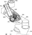
Figure 13 is a partial cutaway view, shows the motor-driven of stack-mounted shown in Figure 10 that is in extended position and dials the chain device.
The specific embodiment
Fig. 1 is the lateral plan at a bicycle rear portion, has adopted the specific embodiment according to bicycle speed-varying unit 10 of the present invention, comprises that one motor-driven group of chain device 14 and is installed in the motion sensor 18 on the cycle frame 22.Say that more specifically comprise that the chain wheel assembly 28 of a plurality of sprocket wheels 28 (A-G) is installed around a wheel shaft 32 (Fig. 7) coaxially and rotationally, wheel shaft 32 forms the part of a loose boss formula wheel hub 320.Shown in Fig. 1-6, dial chain device 14 and comprise a substrate 44 that has axis hole 48, just can be installed on the vehicle frame 22 by making wheel shaft 32 pass axis hole 48 and nut 52 being screwed on the wheel shaft 32 like this dialling chain device 14.By screw 64 and 66 is inserted on the electric motor units cover plate 60 respective aperture 70 and 74 and electric motor units shell 56 on respective aperture 78 and 82, and the screw 86 and 90 on the insertion substrate 44, make electric motor units shell 56 and electric motor units cover plate 60 form the part of substrates 44.
Pass the oscillating axle 100 that extend in hole 102 on the substrate and the hole on the crotch 96 103 by one, and one passed the oscillating axle 112 that extend in hole 113 on the electric motor units shell 56 and the hole on the crotch 98 104, and a link member 94 that has crotch 96 and 98 is pivotably connected on substrate 44 and electric motor units 56.Like this, crotch 96 is between substrate 44 and electric motor units shell 56, and crotch 98 is between electric motor units shell 56 and electric motor units cover plate 60.Bolt of rear end plate 111 (only showing one among Fig. 4) extends into the hole 115 on crotch 96 and 98, so that fix oscillating axle 100 and 112 on the throne.Shaft part 150A (Fig. 6) by an oscillating axle 150 (it passes the hole 116 on the link member 108), one link member 108 is pivotably connected in electric motor units shell 56, and by the shaft part 150B of an oscillating axle 150 (it passes the hole 154 on the link member 130), a link member 130 is pivotably connected in electric motor units shell 56.As below going through, oscillating axle 150 also plays an actuator shaft, dials the chain device to move.By passing the hole 164 on the link member 94 and passing the oscillating axles 160 that extend in the hole 168 and 170 on the movable piece 158, the other end of link member 94 is pivotably connected in movable piece 158.Similarly,, pass the hole 178 on the link member 130 and pass the rocking pins 172 that extend in the hole 180 and 182 on the movable piece 158, the other end of link member 108 and 130 is pivotably connected in movable piece 158 by passing the hole 174 on the link member 108.Extend in the hole 184 that rocking pin 172 also passes on the distance piece 188, and this distance piece is between link member 108 and 130.Like this, electric motor units shell 56, link member 94,108 and 130, formed one " four bars " formula connecting rod mechanism (wherein link member 108 and 130 plays " bar ") with movable piece 158, made movable piece 158 to move with respect to substrate 44 and electric motor units shell 56.One fairleader 190 that has track adjusting wheel 194 and tension wheel 198 is installed on the movable piece 158 in known manner swingably by an oscillating axle 199, so that switch chain 200 between chain wheel set 28 (A-G).
By hole 208 keys on actuator arm 204 1 ends being connected on the plane 210 on the oscillating axle 150, an actuated piece that will be actuator arm 204 forms can not swingingly be installed on the oscillating axle 150.The other end of actuator arm 204 rests on the abutment face 211A and 211B that forms on link member 108 and 130 usually, and a hole or groove 212 are arranged, in order to hold first end 214 of a coil spring 218, spring 218 coiling distance pieces 188.The hole 226 that second end 222 of spring 218 inserts on the attaching parts 108.Sleeve pipe 230 and 234 lays respectively between spring 218 and link member 108 and 130 to reduce the friction between spring 218 and link member 108 and 130 as far as possible.
As illustrated in Figures 5 and 6, electric motor units shell 56 comprises one first housing parts 56A, one second housing parts 56B, and a packing ring 250 between the first housing parts 56A and the second housing parts 56B.Being positioned within the electric motor units shell 56 is a mounting bracket 254, and this support is positioned within the groove 258 and the groove 260 on the second housing parts 56B on the first housing parts 56A.Motor 262 with an axle drive shaft 263 is rigidly fixed on the mounting bracket 254 by screw 264 and 268.Motor 262 is by the signal control that receives on an electric bus 272, and this electric bus is connected in a control unit (Fig. 1), and the latter is connected on the vehicle frame 22 by mounting bracket 280.Motor control unit 276 also is connected in a control center (not shown, but generally be installed on the handle bar of bicycle) by an electric bus 284.
One gear on worm 290 is fixed on the motor driving shaft 263 by a check screw 263, to drive oscillating axle 150 by gear reduction unit 800.Gear reduction unit 800 comprises one and gear on worm 290 ingear gear wheel in large diameter 804.Gear wheel in large diameter 804 is installed on the first housing parts 56A swingably by an oscillating axle 808, and 808 of oscillating axles are located at the first housing parts 56A and go up in the groove 810 that forms.One small diameter gear 814 is not fixed together with gear wheel in large diameter 814 swingably, and meshes with another gear wheel in large diameter 818.Gear wheel in large diameter 818 is installed on the first housing parts 56A swingably by an oscillating axle 822, and 822 of oscillating axles are located at the first housing parts 56A and go up in the groove 826 that forms.One small diameter gear 830 is not fixed on swingably on the oscillating axle 822 and with an elevating arc 834 and meshes, and the latter is fixed on the oscillating axle 150 un-rotatably.Oscillating axle 150 extends by the hole on the first housing parts 56A 836 and by the hole on the second housing parts 56B 838.On the opposite flank of elevating arc 834, be provided with O-ring seals 840 and 844, in case dirt enters electric motor units shell 56 by perforate 836 and 838 around oscillating axle 150.One potentiometer 870 is installed on the shaft part 150A of oscillating axle 150, with the turned position of wobble detection axle 150 and the turned position of movable piece 158.
In operation, motor 262 drives oscillating axle 150 by gear reduction unit 800 conter clockwises, so that fairleader 190 switches to a minor diameter sprocket wheel 28 (A-G) with chain 200 from a large diameter sprocket 28 (A-G), and motor 262 drives oscillating axle 150 by gear reduction unit 800 cws, so that fairleader 190 switches to a large diameter sprocket 28 (A-G) with chain 200 from a minor diameter sprocket wheel 28 (A-G).When motor 262 conter clockwises drove oscillating axle 150, actuator arm 204 rotated counterclockwise and upwards draws first end 214 of spring 218.If there is no to the tangible resistance of motion of movable piece 158, actuator arm 204 just still is positioned on abutment face 211A and the 211B so, and the upward movement of actuator arm 108 makes spring 218 upwards raise on distance piece 188.This just makes movable piece 158 move than minor sprocket 28 (A-G) towards one then, and first end 214 of spring 218 is reversed around distance piece 188.
Yet, if the motion to movable piece 158 applies a very big resistance, for example as rider not to pedal the time, actuator arm 204 just raises from abutment face 211A and 211B so, and that movable piece 158 still keeps is motionless, and the upward movement of actuator arm 204 makes spring first end 214 reverse around distance piece 218, has increased the tension force on the coil spring 218 like this.Coil spring 218 has just been preserved the energy that is used for gear-change operation like this, till the sources of resistance of the motion of movable piece 158 is eliminated, for example as rider again to pedal the time.When this resistance was eliminated, movable piece 158 moved towards a minor diameter sprocket wheel 28 (A-G), and the abutment face 211A on link member 108 and 130 and 211B raise until they contact activated arms 204.
Should be noted that coil spring 218 also plays a shock absorbers under the situation of bicycle whereabouts and group chain device colliding surface.Like this, when movable piece 158 from the left side (Fig. 2) when being clashed into, movable piece trends towards moving down.Can understand from Fig. 4, this just makes abutment face 211A and 211B leave actuator arm 204 and moves downward, has so just absorbed vibration.
When motor 262 along clockwise direction during pendulum rotating moving axis 150 actuator arm 204 be pressed against on abutment face 211A and the 211B, this just makes movable piece 158 move towards a large diameter sprocket 28 (A-G).
Motion sensor 18 provides the information about the rotary state of chain wheel set 28 (A-G).This information can be used to determine the rotating speed of chain wheel set 28 (A-G) and/or the turned position of chain wheel set 28 (A-G).This information is used to determine also whether and when starter motor 262 is dialled the chain device to move.For example, if chain wheel set 28 (A-G) so just to the very big resistance of mobile generation of movable piece 158, may wish to postpone gear-change operation until the rider again to pedal not rotating.And, if chain wheel set 28 (A-G) comprises gear shift supplementary structure (below will describe) in some position, may wish only ability starter motor 262 when the gear shift supplementary structure is in an ideal position with respect to group chain device track adjusting wheel 199 so.
As Fig. 1, shown in 2,7 and 8, motion sensor 18 comprises a sensor holding element 300 of installing coaxially with chain wheel assembly 28, and sensor holding element 300 can rotate with chain wheel assembly like this.One group of first sensing part 304 that is signal generation part form, magnet for example is along circumferentially being embedded in the sensor holding element 300 or along circumferentially installing around sensor holding element 300, so that rotate with sensor holding element 300.One second sensing part 308 is connected in substrate 44 or installs extremely near sensor holding element 300, makes sensor holding element 300 to rotate with respect to second sensing part 308.In the present embodiment, second sensing part 308 comprises 310, one the first sensor unit 308A that are communicated with a plurality of first sensing parts 304 of framework and the second sensor unit 308B who is communicated with a plurality of first sensing parts 304 that are connected in substrate 44 by bolt 311.Each sensor unit 308A and 308B comprise the signal receiving element of magnetic signal receptor and so on, and first sensor unit 308A is upwards departing from the second sensor unit 308B week.Like this, at first receive the rotation direction that just can determine chain wheel assembly 28 from the magnetic signal of each first sensing part 304 based on which sensor unit 308A and 308B.Except traditional utilization for the lasting revolution of chain wheel assembly 28 the time that receives the disappearance between the magnetic signal, the time that disappears between the first sensor unit 308A received signal and the second sensor unit 308B received signal for a given revolution of chain wheel assembly 28 provides second Data Source about the rotating speed of chain wheel assembly 28.The signal that is received is communicated to control unit 276 by an electric bus 309, electric bus 309 structurally with join from the electric bus 272 of motor 262 and form an electric bus 313 (Fig. 1) of concentrating.
In the present embodiment, sensor holding element 300 can be installed on the wheel hub 320 of a loose boss formula.Wheel hub 320 comprises a hub shell 324 and a pair of spoke flange 328 and 330 that has spoke hole 334 and 338 respectively, is used to admit wheel hub 320 is installed in spoke (not shown) on the wheel rim (not shown).One columniform sprocket wheel installing sleeve 340 is rotatably mounted around wheel shaft 32 by an one-way clutch mechanism (not shown), make when chain wheel assembly 28 during only along a direction rotation sprocket wheel installing sleeve 340 turning effort is delivered to hub shell 324 from chain wheel assembly 28.The 26S Proteasome Structure and Function that comprises the wheel hub 320 of sprocket wheel installing sleeve 340 and one-way clutch mechanism is known, so will omit the detailed description to these parts.
One group of spline 350 is along circumferentially being formed on the outer peripheral face of sprocket wheel installing sleeve 340, so that mesh with the complementary splines 354 that forms on the inner peripheral surface of sensor holding element 300.Similarly the spline (not shown) is formed on the inner peripheral surface of each sprocket wheel 28 (A-G).In the present embodiment, be provided with the width location spline 358 bigger than other splines, so that with the similarly positioning groove (not shown) engagement of big width on sprocket wheel installing sleeve 340, sensor holding element 300 can only be installed on the sprocket wheel installing sleeve 340 at a turned position like this.For the same reason, on the inner peripheral surface of each sprocket wheel 28 (A-G), be formed with similar location spline (not shown).Like this, not only sensor holding element 300 and sprocket wheel 28 (A-G) will only be installed on the sprocket wheel installing sleeve 340 at a turned position, and sensor holding element 300 with respect to the turned position of chain wheel assembly 28 with scheduled.When chain wheel set 28 (A-G) have the gear shift supplementary structure in case auxiliary with chain when a sprocket wheel is transformed on another sprocket wheel, this is particularly useful, described in detail as follows.
The free end of sprocket wheel installing sleeve 340 comprises a threaded inner peripheral surface 360, meshes in order to the threaded outer peripheral face 364 with a lock ring 368.Lock ring 368 is screwed into sprocket wheel installing sleeve 340, and just chain wheel assembly 28 and sensor holding element 300 are fixed on the wheel hub 320 un-rotatably.Lock ring 368 also comprises one group of spline 370, in order to instrument (not shown) engagement, so just can be contained in lock ring 368 on the sprocket wheel installing sleeve 340 on demand or unload from it.
Fig. 9 is the lateral plan according to another embodiment of chain wheel assembly 28 ' of the present invention.In this embodiment, omitted sensor holding element 300.But general configuration and lock ring shown in Figure 7 368 identical lock rings 368 ' play a part the sensor holding element.Wherein be embedded in the lock ring 368 ' or be installed on the lock ring 368 '.And chain wheel assembly 28 ' comprises the gear shift supplementary structure, so that a chain moves to another sprocket wheel from a sprocket wheel.Use sprocket wheel 28F ' and 28G ' as an example, sprocket wheel 28 ' comprises a gear shift supplementary structure 400, its form is for being positioned at groove 404 and one or more angled and/or the splay sprocket 408 on the sprocket wheel 28G ' side, so that chain is transferred to sprocket wheel 28G ' from sprocket wheel 28F '.This structure is known now, and for example is being described in the US Patent 4,889,521, and this patent is hereby expressly incorporated by reference.Sprocket wheel 28G ' also comprises a gear shift supplementary structure 410, and its form is for being positioned at groove 414 and one or more angled and/or the splay sprocket 418 on the sprocket wheel 28G ' side, so that chain is transferred to sprocket wheel 28F ' from sprocket wheel 28G '.Adopt this gear shift supplementary structure, dial the chain device to shift chain be very good when track adjusting wheel 199 starts when the gear shift supplementary structure very much.This state can be determined by motion sensor according to the present invention.
Figure 10 is the exploded drawings that motor-driven according to the present invention is dialled another embodiment of chain device 500.Motor-driven group of chain device shown in Figure 1 has one to form the motor of one with substrate, but motor is and one of them link member forms one in the present embodiment.Say more specifically, dial chain device 500 and comprise a substrate 504 that this substrate has one and is installed in hold-down bolt 506 on the vehicle frame 22 in order to will dial chain device 500.One link member 508 is installed on the substrate 504 swingably by an oscillating axle 510, and this oscillating axle 510 passes a hole 514 on the link member 508 and passes hole 518 and 522 on the substrate 504.One link member 530 is installed on the substrate 504 swingably by screw 534 and 538, and this screw 534 and 538 passes on the substrate 504 corresponding hole 544 and 548 and enter corresponding screw 554 and 558 on the link member 530.One movable piece 560 is pivotably connected in the other end of link member 508 by screw 564 and 568, and this screw 564 and 568 passes corresponding hole 574 and 578 and enter on the link member 508 corresponding screw 584 and 588.Movable piece 560 also is pivotably connected at the other end of link member 530 by a tubular nut 594, and this tubular nut passes a hole 604 on the movable piece 560 and passes a hole 618 on the link member 530.One tubular screw 598 passes a hole 608 on the movable piece 560, passes a hole 610 on the elevating arc 780, passes a hole 611 on the brush spare 612, by a hole 613 on the resistance contact 614, and is screwed into tubular nut 594.Movable piece 560, tubular nut 594, tubular screw 598, elevating arc 780 and brush spare 612 rotate with respect to link member 530 together, and resistance contact 614 keeps motionless.One fairleader 650 that has track adjusting wheel 654 and tension wheel 658 is installed on the movable piece 560 swingably by a threaded shaft 660 in a conventional manner, and threaded shaft 660 is screwed into the screw 664 on the movable piece 560.
In this embodiment, link member 530 comprises a cylindrical hole 700, and the motor 704 of a band axle drive shaft 708 is housed in it.One driven wheel 712 is nonrotatably mounted tO on the axle drive shaft 708 so that mesh with a bevel gear 716.As shown in figure 11, bevel gear 716 has the adapter shaft 720 of a wounded in the battle key 724, complementary splines 728 engagements on spline 724 and a tween drive shaft 730 1 ends, tween drive shaft 730 can not rotate with respect to adapter shaft 720 like this, but tween drive shaft 730 can move a certain distance vertically with respect to adapter shaft 720.The other end of tween drive shaft 730 is connected in first clutch discs 734 un-rotatably, and the latter has the one group of hemispherical groove 738 that forms on the side that deviates from bevel gear 716.One group of ball 740 is contained in the hemispherical groove 738.One is pivotably connected in movable piece by a screw 748 with elevating arc 780 ingear intermediate gears 744, and screw 748 passes a hole 752 on the movable piece 560 and enters a screw on intermediate gear 744.One second clutch discs 760 is nonrotatably mounted tO on the intermediate gear 744, and wherein second clutch discs 760 comprises one group of hemispherical groove, in order to hold this group ball 740.
To second clutch discs 760, ball 740 is contained in groove 738 and 764 with pawl formula relation first clutch discs 734 like this by spring 770 biasings.Like this, bevel gear 716 and intermediate gear rotate together as one unit usually, unless a tangible resistance is applied on the intermediate gear 744.When tangible resistance was applied on the intermediate gear 744, the rotation of bevel gear 716 just made ball 740 leave groove 738 and/or 764, so just tween drive shaft 730 was pushed to the left among Figure 11 and was allowed bevel gear 716 and intermediate gear 744 middle relatively rotating.When the obvious resistance of intermediate gear 744 was eliminated, ball 740 meshed with groove 738 and 764 again, and intermediate gear 744 continues to rotate with bevel gear 716.Like this, the rotation of axle drive shaft 708 just makes elevating arc 780 move movable piece 560 with respect to link member 508 and 530, shown in Figure 12 and 13.Movable piece 560 can cooperatively interacting by brush spare 612 and resistance contact 614 determine that both have formed a potentiometer with respect to the position of link member 508 and 530.
Although more than be description, can make further change and do not exceed the spirit and scope of the present invention various embodiments of the invention.For example, can change size, shape, position or the orientation of various parts on demand.The effect of a part can be finished with two, and vice versa.There is no need to represent simultaneously In a particular embodiment all advantages.Every feature unlike the prior art, independent or with other characteristics combination, also should be considered to the inventor and do the further independent description of invention, comprise the structural and/or functional concept of implementing by this feature.
Electric motor units shell 56 can form a part with substrate 44, and sensor unit 308A and 308B can be formed directly on the substrate 44 or dial on some other parts of chain device.The position probing potentiometer can be positioned on the electric motor units shell 56 or dial any position on the chain device.Can omit gear reduction unit 800 and available some other device (for example stepping motor) comes direct control to dial the chain device.Like this, scope of the present invention should or not concentrate on ad hoc structure or the preliminary discussion of feature limits by disclosed concrete structure.
Claims (8)
1. dial the chain device for one kind, comprising:
One substrate;
One movable piece;
One connecting rod mechanism, it comprises a link member that is connected in this substrate and is connected in this movable piece, makes that this movable piece can be with respect to this substrate motion, and wherein this link member is pivotably connected in one of this substrate and this movable piece by a first connecting rod attaching parts;
One is used to make the motor of this first connecting rod attaching parts rotation;
Wherein this movable piece responds the rotation of this first connecting rod attaching parts and moves with respect to this substrate; And
One is connected in the first sensor of this substrate, in order to the rotation of the operated chain wheel assembly of this group of sensing chain device.
2. as claimed in claim 1 group of chain device is characterized in that this first sensor comprises a magnetic pickup device.
3. as claimed in claim 1 group of chain device is characterized in that, comprises that also one is connected in second sensor of this substrate, in order to the rotation of the operated chain wheel assembly of this group of sensing chain device.
4. as claimed in claim 1 group of chain device is characterized in that, this first sensor is upwards departing from this second sensor week.
5. as claimed in claim 4 group of chain device is characterized in that this first sensor comprises one first magnetic pickup device, and this second sensor comprises one second magnetic pickup device.
6. as claimed in claim 1 group of chain device is characterized in that this first sensor is positioned on this substrate.
7. as claimed in claim 1 group of chain device is characterized in that, comprises that also one is connected in the position detecting mechanism of this group chain device, in order to detect the position of this movable piece with respect to this substrate.
8. as claimed in claim 7 group of chain device is characterized in that, this position detecting mechanism comprises that one is positioned at the potentiometer on this substrate.
Applications Claiming Priority (2)
| Application Number | Priority Date | Filing Date | Title |
|---|---|---|---|
| US09/216685 | 1998-12-18 | ||
| US09/216,685 US6162140A (en) | 1998-12-18 | 1998-12-18 | Motor driven derailleur |
Related Parent Applications (1)
| Application Number | Title | Priority Date | Filing Date |
|---|---|---|---|
| CN99126417A Division CN1114543C (en) | 1998-12-18 | 1999-12-17 | Motor-driven chain shifter |
Publications (2)
| Publication Number | Publication Date |
|---|---|
| CN1515450A CN1515450A (en) | 2004-07-28 |
| CN1298585C true CN1298585C (en) | 2007-02-07 |
Family
ID=22808089
Family Applications (2)
| Application Number | Title | Priority Date | Filing Date |
|---|---|---|---|
| CN99126417A Expired - Fee Related CN1114543C (en) | 1998-12-18 | 1999-12-17 | Motor-driven chain shifter |
| CNB031234313A Expired - Fee Related CN1298585C (en) | 1998-12-18 | 1999-12-17 | Chain wheel device driven by electric motor |
Family Applications Before (1)
| Application Number | Title | Priority Date | Filing Date |
|---|---|---|---|
| CN99126417A Expired - Fee Related CN1114543C (en) | 1998-12-18 | 1999-12-17 | Motor-driven chain shifter |
Country Status (9)
| Country | Link |
|---|---|
| US (1) | US6162140A (en) |
| EP (2) | EP1609716B1 (en) |
| JP (1) | JP3458086B2 (en) |
| CN (2) | CN1114543C (en) |
| DE (2) | DE69940496D1 (en) |
| PL (1) | PL337269A1 (en) |
| RU (1) | RU2248297C2 (en) |
| SK (1) | SK182199A3 (en) |
| TW (1) | TW446665B (en) |
Cited By (1)
| Publication number | Priority date | Publication date | Assignee | Title |
|---|---|---|---|---|
| TWI627101B (en) * | 2016-10-14 | 2018-06-21 | 彥豪金屬工業股份有限公司 | Derailleur assembly |
Families Citing this family (97)
| Publication number | Priority date | Publication date | Assignee | Title |
|---|---|---|---|---|
| US6293882B1 (en) * | 1999-12-10 | 2001-09-25 | Shimano, Inc. | Operating force compensating apparatus for a bicycle transmission |
| US6244415B1 (en) * | 1999-12-30 | 2001-06-12 | Shimano, Inc. | Motor controlled shift control device including an idler gear for a bicycle transmission |
| IT1320581B1 (en) * | 2000-08-03 | 2003-12-10 | Campagnolo Srl | FRONT BIKE FRONT DERAILLEUR WITH ELECTRIC CONTROL MOTOR AND GEAR REDUCER. |
| IT1321071B1 (en) * | 2000-11-17 | 2003-12-30 | Campagnolo Srl | ACTUATOR DEVICE FOR A BIKE FRONT DERAILLEUR, WITH CONNECTION JOINT TO THE DRIVEN SHAFT. |
| ITTO20010678A1 (en) * | 2001-07-11 | 2003-01-11 | Campagnolo Srl | ELECTRONIC CONTROL GROUP USABLE ON BOARD A BICYCLE. |
| US6726586B2 (en) * | 2001-11-09 | 2004-04-27 | Shimano Inc. | Motorized bicycle actuator assembly |
| US20030171176A1 (en) * | 2002-03-07 | 2003-09-11 | Shimano, Inc. | Bicycle rear derailleur |
| JP3696190B2 (en) * | 2002-08-28 | 2005-09-14 | 株式会社シマノ | Bicycle rotation detector |
| JP3645877B2 (en) * | 2002-09-06 | 2005-05-11 | 株式会社シマノ | Bicycle rear derailleur |
| US6945888B2 (en) * | 2002-11-21 | 2005-09-20 | Shimano, Inc. | Combined analog and digital derailleur position processing apparatus |
| US6997835B2 (en) * | 2002-11-26 | 2006-02-14 | Shimano, Inc. | Electrically operated derailleur with power storing mechanism |
| US7033294B2 (en) * | 2003-06-11 | 2006-04-25 | Specialized Bicycle Components | Bicycle rear derailleur guard |
| US7290458B2 (en) * | 2004-02-24 | 2007-11-06 | Shimano, Inc. | Bicycle derailleur with a motor disposed within a linkage mechanism |
| US7467567B2 (en) * | 2004-02-24 | 2008-12-23 | Shimano, Inc. | Gear reduction apparatus for a bicycle component |
| US7291079B2 (en) | 2004-02-26 | 2007-11-06 | Shimano Inc. | Motorized front derailleur assembly with saver arrangement |
| US6979009B2 (en) * | 2004-02-26 | 2005-12-27 | Shimano Inc. | Motorized bicycle derailleur assembly |
| US7331890B2 (en) | 2004-02-26 | 2008-02-19 | Shimano Inc. | Motorized front derailleur mounting member |
| US7341532B2 (en) | 2004-02-27 | 2008-03-11 | Shimano Inc. | Electric derailleur motor unit |
| EP1568596B1 (en) * | 2004-02-27 | 2007-07-11 | Campagnolo S.R.L. | Powered actuator for a bicycle gearshift, with a controlled friction mechanism |
| JP4145836B2 (en) * | 2004-06-15 | 2008-09-03 | 株式会社シマノ | Bicycle shift drive |
| JP2006001438A (en) * | 2004-06-18 | 2006-01-05 | Shimano Inc | Control device for bicycle, and seat pillar for bicycle |
| JP2006137206A (en) * | 2004-11-10 | 2006-06-01 | Shimano Inc | Electrical component for bicycle and derailleur for bicycle using the same |
| US7798929B2 (en) | 2004-12-07 | 2010-09-21 | Shimano, Inc. | Method and apparatus for controlling a bicycle transmission to compensate for power supply characteristics |
| JP2006219029A (en) * | 2005-02-10 | 2006-08-24 | Shimano Inc | Electric driving device for bicycle |
| US7442136B2 (en) | 2005-02-18 | 2008-10-28 | Shimano Inc. | Motorized bicycle derailleur assembly |
| US7503863B2 (en) | 2005-02-18 | 2009-03-17 | Shimano Inc. | Bicycle derailleur motor unit assembly |
| US20060186158A1 (en) * | 2005-02-18 | 2006-08-24 | Shimano, Inc. | Water resisting apparatus for a bicycle electrical component |
| US7243937B2 (en) * | 2005-02-18 | 2007-07-17 | Shimano, Inc. | Bicycle control apparatus |
| US7267352B2 (en) * | 2005-02-18 | 2007-09-11 | Shimano, Inc. | Apparatus for mounting an electrical component to a bicycle |
| DE102005034330A1 (en) | 2005-07-22 | 2007-01-25 | Sram Deutschland Gmbh | articulation |
| JP4065286B2 (en) * | 2005-08-09 | 2008-03-19 | 株式会社シマノ | Bicycle electric derailleur |
| JP2007203954A (en) * | 2006-02-03 | 2007-08-16 | Shimano Inc | Derailleur for bicycle |
| US7704173B2 (en) | 2006-02-08 | 2010-04-27 | Shimano Inc. | Motorized bicycle derailleur assembly |
| US8025598B2 (en) * | 2006-10-24 | 2011-09-27 | Shimano, Inc. | Low profile rear derailleur with a chain receiving space |
| US8066597B2 (en) * | 2007-03-15 | 2011-11-29 | Shimano, Inc. | Electrically operated derailleur with force overload protection |
| US7837213B2 (en) | 2007-04-16 | 2010-11-23 | Trek Bicycle Corporation | Bicycle rear wheel suspension system |
| US7703785B2 (en) * | 2007-08-16 | 2010-04-27 | Trek Bicycle Corporation | Bicycle derailleur system |
| US8137223B2 (en) * | 2007-05-16 | 2012-03-20 | Shimano Inc. | Bicycle rear derailleur |
| ITMI20071871A1 (en) * | 2007-09-28 | 2009-03-29 | Campagnolo Srl | SUPPORT FOR FRONT BICYCLE CHANGE AND FRONT BICYCLE CHANGE INCLUDING SUCH SUPPORT |
| ITMI20072062A1 (en) * | 2007-10-25 | 2009-04-26 | Campagnolo Srl | BICYCLE CHANGE |
| US7942768B2 (en) * | 2008-01-28 | 2011-05-17 | Shimano, Inc. | Electrically operated derailleur that re-engages a disengaged derailleur force overload clutch |
| US8025597B2 (en) * | 2008-02-20 | 2011-09-27 | Shimano Inc. | Bicycle component position correcting device |
| US7892122B2 (en) * | 2008-02-22 | 2011-02-22 | Shimano, Inc. | Electrically operated derailleur with a power storing mechanism |
| EP2110304A1 (en) * | 2008-04-17 | 2009-10-21 | CAMPAGNOLO S.r.l. | Bicycle derailleur |
| DE102008031162B4 (en) | 2008-07-03 | 2021-10-21 | Sram Deutschland Gmbh | Multiple chain sprocket for a bicycle |
| KR101074080B1 (en) * | 2009-05-29 | 2011-10-17 | 한양대학교 산학협력단 | Gear bicycle |
| KR100966120B1 (en) * | 2009-12-28 | 2010-06-25 | 이창용 | Automatic transmission gear box of bicycle |
| US20120035011A1 (en) * | 2010-08-09 | 2012-02-09 | Menachem Haim | Electro mechanical bicycle derailleur actuator system and method |
| DE112012005399T5 (en) | 2011-12-22 | 2014-09-04 | Industries Rad Inc. | Composite bicycle frame with integrated electrical connections and method of making same |
| EP2610159A1 (en) * | 2011-12-30 | 2013-07-03 | J.D Components Co., Ltd. | Automatic gear shifting bicycle with gearshift protection mechanism |
| US8979683B2 (en) * | 2012-01-31 | 2015-03-17 | Shimano Inc. | Bicycle electric actuator unit |
| US9394030B2 (en) * | 2012-09-27 | 2016-07-19 | Sram, Llc | Rear derailleur |
| US8974331B2 (en) * | 2012-12-10 | 2015-03-10 | Shimano Inc. | Bicycle derailleur |
| US9303763B2 (en) | 2012-12-10 | 2016-04-05 | Shimano, Inc | Bicycle rear derailleur |
| TWI555673B (en) * | 2012-10-04 | 2016-11-01 | 島野股份有限公司 | Bicycle derailleur |
| JP2014091384A (en) | 2012-11-01 | 2014-05-19 | Shimano Inc | Motor unit for driving bicycle transmission |
| TWI515145B (en) * | 2012-12-03 | 2016-01-01 | 黃永松 | Torque sensing gear structure of an electronic bike |
| US8888620B2 (en) * | 2012-12-05 | 2014-11-18 | Shimano Inc. | Front derailleur |
| US8864611B2 (en) * | 2012-12-05 | 2014-10-21 | Shimano Inc. | Front derailleur |
| US9005059B2 (en) * | 2013-03-27 | 2015-04-14 | Shimano Inc. | Rear derailleur |
| US9676444B2 (en) * | 2013-10-23 | 2017-06-13 | Sram, Llc | Electromechanical rear derailleur |
| US9085340B1 (en) * | 2014-03-14 | 2015-07-21 | Tien Hsin Industries Co., Ltd. | Electronic front derailleur |
| US9776684B2 (en) * | 2014-10-17 | 2017-10-03 | Tektro Technology Corporation | Derailleur |
| TWI574881B (en) * | 2014-10-17 | 2017-03-21 | 彥豪金屬工業股份有限公司 | Derailleur assembly |
| US10370060B2 (en) * | 2015-10-30 | 2019-08-06 | Shimano Inc. | Bicycle electrical component assembly |
| DE102015205736A1 (en) | 2015-03-30 | 2016-10-06 | Sram Deutschland Gmbh | Bicycle rear wheel and pinion assembly |
| US10900547B2 (en) | 2015-03-30 | 2021-01-26 | Sram Deutschland Gmbh | Drive arrangement for a bicycle and tool |
| DE102015210503A1 (en) | 2015-06-09 | 2016-12-15 | Sram Deutschland Gmbh | Rear sprocket assembly for a bicycle, especially a pedelec |
| JP6499028B2 (en) * | 2015-06-25 | 2019-04-10 | 株式会社シマノ | Bicycle shift control device for controlling transmission and bicycle shift control system including transmission |
| US10703441B2 (en) | 2015-07-03 | 2020-07-07 | Sram Deutschland Gmbh | Drive arrangement for a bicycle |
| US9873482B2 (en) * | 2015-10-09 | 2018-01-23 | Shimano Inc. | Bicycle front derailleur |
| US9656723B1 (en) * | 2015-12-14 | 2017-05-23 | Shimano Inc. | Electrical bicycle derailleur |
| ITUA20163996A1 (en) * | 2016-05-31 | 2017-12-01 | Campagnolo Srl | Electric bicycle derailleur |
| IT201700018702A1 (en) * | 2017-02-20 | 2018-08-20 | Campagnolo Srl | Rear electric derailleur of bicycle |
| DE102018001253A1 (en) * | 2017-03-20 | 2018-09-20 | Sram Deutschland Gmbh | Rear derailleur for coaxial mounting |
| IT201700035716A1 (en) * | 2017-03-31 | 2018-10-01 | Campagnolo Srl | Bicycle rear derailleur |
| US10773773B2 (en) * | 2017-06-07 | 2020-09-15 | Shimano Inc. | Electric bicycle derailleur |
| JP7236799B2 (en) * | 2017-07-11 | 2023-03-10 | 株式会社シマノ | Bicycle control device and bicycle suspension system provided with the same |
| US10501147B2 (en) * | 2017-08-22 | 2019-12-10 | Shimano Inc. | Bicycle derailleur |
| DE102017010348A1 (en) | 2017-11-09 | 2019-05-09 | Sram Deutschland Gmbh | Electromechanical rear derailleur |
| US10981626B2 (en) * | 2018-03-20 | 2021-04-20 | Sram Deutschland Gmbh | Drive arrangement for a bicycle |
| TWM562816U (en) * | 2018-04-03 | 2018-07-01 | 彥豪金屬工業股份有限公司 | Derailleur assembly |
| TWM562815U (en) * | 2018-04-03 | 2018-07-01 | 彥豪金屬工業股份有限公司 | Derailleur assembly |
| DE102018207493A1 (en) | 2018-05-15 | 2019-11-21 | Sram Deutschland Gmbh | A bicycle adjusting device and method of controlling or adjusting such adjusting devices |
| US11498643B2 (en) * | 2019-02-26 | 2022-11-15 | Shimano Inc. | Bicycle electric derailleur |
| US11046390B2 (en) * | 2019-03-25 | 2021-06-29 | Hazem Nihad Hamed | Automatic bicycle shifter and electrical derailleur |
| DE102020000827A1 (en) * | 2019-04-25 | 2020-10-29 | Sram Deutschland Gmbh | Electromechanical switching mechanism for coaxial assembly |
| US11608139B2 (en) * | 2019-05-13 | 2023-03-21 | Shimano Inc. | Bicycle rear derailleur |
| JP7309476B2 (en) * | 2019-06-25 | 2023-07-18 | 株式会社シマノ | Control device for human-powered vehicle and transmission system for human-powered vehicle |
| DE102020210354A1 (en) * | 2019-08-23 | 2021-02-25 | Sram Deutschland Gmbh | BICYCLE DERAILLEUR WITH ADJUSTMENT DISPLAY |
| US11535339B2 (en) * | 2019-08-30 | 2022-12-27 | Shimano Inc. | Bicycle derailleur |
| TWI729557B (en) * | 2019-11-06 | 2021-06-01 | 天心工業股份有限公司 | Rear derailleur |
| ES1241315Y (en) | 2019-11-21 | 2020-07-29 | Zuma Innovation S L | Rear derailleur with wireless floating drive |
| USD958702S1 (en) | 2020-08-05 | 2022-07-26 | Specialized Bicycle Components, Inc. | Bicycle frame |
| US20220081067A1 (en) * | 2020-09-11 | 2022-03-17 | Shimano Inc. | Bicycle derailleur |
| US20230002006A1 (en) * | 2021-06-30 | 2023-01-05 | Shimano (Singapore) Pte. Ltd. | Derailleur for human-powered vehicle |
| US11787505B1 (en) * | 2022-04-12 | 2023-10-17 | Shimano Inc. | Linkage and derailleur for human-powered vehicle |
Citations (6)
| Publication number | Priority date | Publication date | Assignee | Title |
|---|---|---|---|---|
| US4946425A (en) * | 1986-09-16 | 1990-08-07 | Villiger Sohne AG Cigarrenfabriken | Electromechanical bicycle gear shift mechanism |
| DE4022473A1 (en) * | 1990-07-14 | 1992-01-16 | Rolf Dr Meissner | Gearchange for bicycle - has servo motor on gearchange mechanism with remote control unit |
| US5359884A (en) * | 1991-10-22 | 1994-11-01 | Fichtel & Sachs Ag | Displacement sensor for an actuating drive in particular in a vehicle |
| US5470277A (en) * | 1993-07-08 | 1995-11-28 | Campagnolo S.R.L. | Power operated gear change assembly for bicycles |
| US5480356A (en) * | 1994-02-24 | 1996-01-02 | Campagnolo S.R.L. | Speed change device for bicycles |
| CN1125667A (en) * | 1995-03-28 | 1996-07-03 | 王维德 | Method and device for bicycle automatic gearshift with computer control |
Family Cites Families (8)
| Publication number | Priority date | Publication date | Assignee | Title |
|---|---|---|---|---|
| US3919891A (en) * | 1973-10-15 | 1975-11-18 | Brian J Stuhlmuller | Electrical gear changer for chain driven vehicle |
| FR2587079A1 (en) * | 1985-09-11 | 1987-03-13 | Roche Claudia | Electrically controlled dérailleur |
| FR2605969B1 (en) * | 1986-11-04 | 1993-11-12 | Montini Raoul | COMBINED ELECTRIC DERAILLEURS FOR AUTONOMOUS CYCLE ADAPTING TO ANY TYPE OF EXISTING DERAILLEURS |
| JPS63119196U (en) * | 1987-01-28 | 1988-08-02 | ||
| IT1252263B (en) | 1991-11-18 | 1995-06-08 | Catene Calibrate Regina | ELECTROMECHANICAL GEARBOX FOR BICYCLE |
| DE4212320A1 (en) * | 1992-04-13 | 1993-10-14 | Fichtel & Sachs Ag | Electric actuator |
| DE4231761C2 (en) * | 1992-09-23 | 2003-08-21 | Sram De Gmbh | Push rod for swivel movements |
| DE4340471C1 (en) * | 1993-11-27 | 1995-02-02 | Fichtel & Sachs Ag | Derailleur for bicycles |
-
1998
- 1998-12-18 US US09/216,685 patent/US6162140A/en not_active Expired - Lifetime
-
1999
- 1999-11-03 TW TW088119159A patent/TW446665B/en not_active IP Right Cessation
- 1999-12-06 JP JP34568299A patent/JP3458086B2/en not_active Expired - Fee Related
- 1999-12-14 DE DE69940496T patent/DE69940496D1/en not_active Expired - Lifetime
- 1999-12-14 EP EP05020873A patent/EP1609716B1/en not_active Expired - Lifetime
- 1999-12-14 DE DE69943303T patent/DE69943303D1/en not_active Expired - Lifetime
- 1999-12-14 EP EP99310068A patent/EP1010613B1/en not_active Expired - Lifetime
- 1999-12-17 PL PL99337269A patent/PL337269A1/en unknown
- 1999-12-17 SK SK1821-99A patent/SK182199A3/en unknown
- 1999-12-17 CN CN99126417A patent/CN1114543C/en not_active Expired - Fee Related
- 1999-12-17 CN CNB031234313A patent/CN1298585C/en not_active Expired - Fee Related
- 1999-12-20 RU RU99126757/11A patent/RU2248297C2/en not_active IP Right Cessation
Patent Citations (6)
| Publication number | Priority date | Publication date | Assignee | Title |
|---|---|---|---|---|
| US4946425A (en) * | 1986-09-16 | 1990-08-07 | Villiger Sohne AG Cigarrenfabriken | Electromechanical bicycle gear shift mechanism |
| DE4022473A1 (en) * | 1990-07-14 | 1992-01-16 | Rolf Dr Meissner | Gearchange for bicycle - has servo motor on gearchange mechanism with remote control unit |
| US5359884A (en) * | 1991-10-22 | 1994-11-01 | Fichtel & Sachs Ag | Displacement sensor for an actuating drive in particular in a vehicle |
| US5470277A (en) * | 1993-07-08 | 1995-11-28 | Campagnolo S.R.L. | Power operated gear change assembly for bicycles |
| US5480356A (en) * | 1994-02-24 | 1996-01-02 | Campagnolo S.R.L. | Speed change device for bicycles |
| CN1125667A (en) * | 1995-03-28 | 1996-07-03 | 王维德 | Method and device for bicycle automatic gearshift with computer control |
Cited By (1)
| Publication number | Priority date | Publication date | Assignee | Title |
|---|---|---|---|---|
| TWI627101B (en) * | 2016-10-14 | 2018-06-21 | 彥豪金屬工業股份有限公司 | Derailleur assembly |
Also Published As
| Publication number | Publication date |
|---|---|
| EP1609716A2 (en) | 2005-12-28 |
| PL337269A1 (en) | 2000-06-19 |
| US6162140A (en) | 2000-12-19 |
| EP1609716A3 (en) | 2006-02-15 |
| JP2000177674A (en) | 2000-06-27 |
| EP1010613A1 (en) | 2000-06-21 |
| DE69940496D1 (en) | 2009-04-16 |
| DE69943303D1 (en) | 2011-05-05 |
| CN1515450A (en) | 2004-07-28 |
| EP1609716B1 (en) | 2011-03-23 |
| RU2248297C2 (en) | 2005-03-20 |
| TW446665B (en) | 2001-07-21 |
| SK182199A3 (en) | 2000-09-12 |
| CN1114543C (en) | 2003-07-16 |
| JP3458086B2 (en) | 2003-10-20 |
| EP1010613B1 (en) | 2009-03-04 |
| CN1257808A (en) | 2000-06-28 |
Similar Documents
| Publication | Publication Date | Title |
|---|---|---|
| CN1298585C (en) | Chain wheel device driven by electric motor | |
| CN1165766C (en) | Movement sensor used in cooperation with chain wheel assembly of bicycle | |
| CN101513921B (en) | Electrically operated derailleur with a power storing mechanism | |
| CN100441475C (en) | Bicycle electrical component and chain kicking device using the same electrical component for bicycle | |
| CN1248904C (en) | Electrically operated derailleur with energy storage mechanism | |
| CN1309617C (en) | Speed changing and brake controlling unit for bicycle | |
| CN100528684C (en) | Electric driving apparatus for bicycle | |
| US20050277503A1 (en) | Variable speed drive device for bicycle | |
| CN1142876C (en) | Variable-speed unit for bicycle | |
| JPH07251784A (en) | Speed changing device for bicycle | |
| CN1251923C (en) | Motor unit for speed-changing auxiliary device in bicycle transmission | |
| CN103707996B (en) | Bicycle derailleur | |
| CN100335362C (en) | Method and device for preventing bicycle transmission from incorrect gear-shift | |
| US6293882B1 (en) | Operating force compensating apparatus for a bicycle transmission | |
| JP3645962B2 (en) | Bicycle with assist motor | |
| CN1576158A (en) | Shift assist apparatus for a bicycle transmission | |
| CN117048766A (en) | Motor unit for bicycle derailleur | |
| JP3754489B2 (en) | Bicycle with assist motor | |
| TWM644007U (en) | Electronic Transmission Angle Detection Structure | |
| JPH07172325A (en) | Battery driven forklift truck | |
| JP2002137756A (en) | Steering wheel neutral position returning device | |
| JP2003312583A (en) | Bicycle provided with auxiliary transmission gear |
Legal Events
| Date | Code | Title | Description |
|---|---|---|---|
| C06 | Publication | ||
| PB01 | Publication | ||
| C10 | Entry into substantive examination | ||
| SE01 | Entry into force of request for substantive examination | ||
| C14 | Grant of patent or utility model | ||
| GR01 | Patent grant | ||
| CF01 | Termination of patent right due to non-payment of annual fee | ||
| CF01 | Termination of patent right due to non-payment of annual fee |
Granted publication date: 20070207 Termination date: 20181217 |