CN1315547C - Indicating device for aerosol container - Google Patents
Indicating device for aerosol container Download PDFInfo
- Publication number
- CN1315547C CN1315547C CNB998082694A CN99808269A CN1315547C CN 1315547 C CN1315547 C CN 1315547C CN B998082694 A CNB998082694 A CN B998082694A CN 99808269 A CN99808269 A CN 99808269A CN 1315547 C CN1315547 C CN 1315547C
- Authority
- CN
- China
- Prior art keywords
- cap member
- display part
- frame piece
- display device
- ratchet
- Prior art date
- Legal status (The legal status is an assumption and is not a legal conclusion. Google has not performed a legal analysis and makes no representation as to the accuracy of the status listed.)
- Expired - Lifetime
Links
Images


Classifications
-
- A—HUMAN NECESSITIES
- A61—MEDICAL OR VETERINARY SCIENCE; HYGIENE
- A61M—DEVICES FOR INTRODUCING MEDIA INTO, OR ONTO, THE BODY; DEVICES FOR TRANSDUCING BODY MEDIA OR FOR TAKING MEDIA FROM THE BODY; DEVICES FOR PRODUCING OR ENDING SLEEP OR STUPOR
- A61M15/00—Inhalators
- A61M15/0065—Inhalators with dosage or measuring devices
- A61M15/0068—Indicating or counting the number of dispensed doses or of remaining doses
- A61M15/007—Mechanical counters
- A61M15/0071—Mechanical counters having a display or indicator
- A61M15/0073—Mechanical counters having a display or indicator on a ring
-
- A—HUMAN NECESSITIES
- A61—MEDICAL OR VETERINARY SCIENCE; HYGIENE
- A61M—DEVICES FOR INTRODUCING MEDIA INTO, OR ONTO, THE BODY; DEVICES FOR TRANSDUCING BODY MEDIA OR FOR TAKING MEDIA FROM THE BODY; DEVICES FOR PRODUCING OR ENDING SLEEP OR STUPOR
- A61M15/00—Inhalators
- A61M15/0001—Details of inhalators; Constructional features thereof
- A61M15/002—Details of inhalators; Constructional features thereof with air flow regulating means
-
- A—HUMAN NECESSITIES
- A61—MEDICAL OR VETERINARY SCIENCE; HYGIENE
- A61M—DEVICES FOR INTRODUCING MEDIA INTO, OR ONTO, THE BODY; DEVICES FOR TRANSDUCING BODY MEDIA OR FOR TAKING MEDIA FROM THE BODY; DEVICES FOR PRODUCING OR ENDING SLEEP OR STUPOR
- A61M15/00—Inhalators
- A61M15/0065—Inhalators with dosage or measuring devices
- A61M15/0068—Indicating or counting the number of dispensed doses or of remaining doses
- A61M15/007—Mechanical counters
- A61M15/0071—Mechanical counters having a display or indicator
- A61M15/0075—Mechanical counters having a display or indicator on a disc
-
- A—HUMAN NECESSITIES
- A61—MEDICAL OR VETERINARY SCIENCE; HYGIENE
- A61M—DEVICES FOR INTRODUCING MEDIA INTO, OR ONTO, THE BODY; DEVICES FOR TRANSDUCING BODY MEDIA OR FOR TAKING MEDIA FROM THE BODY; DEVICES FOR PRODUCING OR ENDING SLEEP OR STUPOR
- A61M15/00—Inhalators
- A61M15/009—Inhalators using medicine packages with incorporated spraying means, e.g. aerosol cans
-
- G—PHYSICS
- G06—COMPUTING; CALCULATING OR COUNTING
- G06M—COUNTING MECHANISMS; COUNTING OF OBJECTS NOT OTHERWISE PROVIDED FOR
- G06M1/00—Design features of general application
- G06M1/04—Design features of general application for driving the stage of lowest order
- G06M1/041—Design features of general application for driving the stage of lowest order for drum-type indicating means
-
- G—PHYSICS
- G06—COMPUTING; CALCULATING OR COUNTING
- G06M—COUNTING MECHANISMS; COUNTING OF OBJECTS NOT OTHERWISE PROVIDED FOR
- G06M1/00—Design features of general application
- G06M1/28—Design features of general application for zeroising or setting to a particular value
- G06M1/283—Design features of general application for zeroising or setting to a particular value with drums
Abstract
This invention is a usage indicator member (260) disposed in a housing (200), the usage indicator member (260) comprising usage indicia visible to the user which indicates the number of usage cycles completed by or remaining for the indicating device. The indicating member (260) is rotatable mounted in the housing (200) for rotational movement transverse to, in response to axial movement between a cap (220), and a base member (50) of the housing (200).
Description
Background of the present invention
Technical field
In general, the present invention relates to be used for showing the display device of the number that passes through metric dosage, these dosage are scattered out by a spray container, perhaps for staying in this container, specifically, relate to a kind of display device that is suitable for being installed on the spray container.
Background technology
Developed the spray dissemination apparatus, it comprises a dose display, demonstrates the number of the metric dosage of process that is scattered out by this device, perhaps demonstrates the number of the dosage that also stays therein.For example, some disease of patient can be in order to the heal with drugs of spray form distribution, and these medicines can offer patient by suction.In a kind of mode, the spray that has medicine is housed in the container, scatters this spray with a kind of suction apparatus or drive sleeve with the dosage through excess vol or process measurement.In such device, for patient, the number that can determine the metric dosage of process that also stays in this container may be important, this or realize by being presented at the dosage number that wherein also stays, or realize, thereby make the container that when patient needs medicine, does not have a sky also not know by knowing by the dosage number that wherein scatters out.Therefore, for suction apparatus, may be important for also staying the dosage number in the container or providing accurate demonstration for the number of the dosage that has scattered by this container.
Typically, a traditional spray container comprises a body and a valve rod, can press this bar with respect to body, thereby exhales spray and medicine through metric dosage.Typically, this supply for receptacles predetermined number through metric dosage, usually this number is about 200 magnitude, makes that directly the number with the dosage that stays in container is relevant to the number that presses down valve rod and the counting of the number of the metric dosage of process that scatters out accordingly.
In use, this container typically is contained in the housing of suction apparatus, wherein, valve is engaged with a support block in the housing.Thereby supply with the user medicine is to depress the valve of valve rod and inside and discharge the metric dosage of process by move this container with respect to housing, and this dosage offers user by a mouth or a mouth that is stretched by housing typically.After this dosage was provided, the valve rod that spring typically is housed was departed from out container by support block, thereby this container can be moved with respect to housing once more.Like this, provide a metric drug dose of process by container with respect to each circulation of the straight reciprocating motion of housing.
Some drive sleeve or other device that is attached on the medicament reservoir have display device, this display device converts container to the one-way movement or the single cycle motion of display with respect to the straight reciprocating motion of housing, wherein, this display is determined the relative degree that is full of of this container, stay the number of the metric dosage of process wherein, the number of the dosage that has perhaps provided.Though these have display or the drive sleeve of the display device that separates provides the general benefit that can follow the tracks of the number of dosage,, still leave some room for improvement.For example, such display device may comprise complicated moving component, and it may be difficult assembling these parts, and to make them may be expensive.Such device also may be easy to generate because the configuration of the parts of the parts of calibration or cooperation causes the inaccurate of counting, perhaps requires to occupy excessive space in housing, so that hold relatively large or more moving component.Other device also may hinder or disturb air flow and the medicine that is scattered out by suction apparatus.In addition, some device adopts circuit that distribution is counted or noted down.Yet the manufacturing of these devices may be more expensive relatively, and these devices require that typically a power supply is arranged, and may occur easily damaging such as power supply under the condition of humidity in many environment.
Summary of the invention
Speak briefly, the objective of the invention is to refer to be used for showing a kind of display device of the number that passes through metric dosage, this dosage number is scattered out or is still stayed in this container by a container.Described container has a valve rod, and this valve rod is stretched by container in the vertical; This valve rod can move between a closed position and an open position.When valve rod was moved to open position, this container scattered out the metric dosage of process.Display device comprises: a frame piece, be suitable for it is installed on the container, be connected to a cap member on this frame piece movably, be pivotally connected to a display part on the described cap member, and actuator, when this cap member during with respect to the predetermined number of this frame piece axially-movable one, this actuator is suitable for making display part to rotate an increment.
According to the present invention, a kind of display device that is used for showing the number that passes through the dosage that measures is provided, this dosage number scatters out or still stays in this container by a container, and described display device comprises: a frame piece is suitable for it is installed on the container; Be connected to a cap member on the described frame piece movably, described cap member can move along an axial path with respect to described frame piece; One display part, it is arranged between described frame piece and the described cap member; Optionally engage a mechanism of described display part, when described cap member during with respect to described frame piece axially-movable one predetermined number, make described display part rotate an increment, wherein, described axially movable predetermined number is greater than one.
The invention provides apparently higher than the advantage of other spray dissemination apparatus and the display device used with them.Particularly, can make display device dividually, and as needing, it is installed on the spray distribution container of any amount of traditional type, and container or housing are only required very little change, perhaps without any need for change.Also have, display device is made of relative less and simple machine components with driving mechanism together with its display part, and these parts are very easy to make and assembling.Like this, display device is made into more durable, and when being exposed to various disadvantageous environment for use, this display device is not easy to be damaged.In addition, driving mechanism and display part provide reliable display device, and be used for showing the number of the dosage that scatters out by container or still stay the number of the dosage in this container, and, can be made into quite compact configuration to this display device, the use that this configuration can the interference spread device.
Can be expressly understood the present invention and its other purpose and advantage by the detailed description that connects work with reference to following and accompanying drawing.
Description of drawings
Fig. 1 is the top view of a display device, and this device has a watch window;
Fig. 1 A is the top view of display device, shows another embodiment of the watch window that passes the labelling that it can see;
Figure 1B is the top view of display device, shows another embodiment of labelling;
Fig. 2 is the side view that is installed to the display device on the top of a container shown in the section;
Fig. 3 is the top perspective that has the display device of the watch window on the top that is positioned at cap member;
Fig. 3 A has the position in the top perspective along the display device of the watch window of a sidepiece of cap member;
Fig. 4 is the bottom perspective view that has the cap member that is installed in display part wherein;
Fig. 5 is the exploded perspective illustration of cap member shown in Fig. 4 and display part;
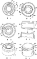
Fig. 6 is the exploded perspective illustration of another embodiment of display device, and this device comprises a frame piece, cap member, display part, ratchet and an actuator and a spring;
Fig. 7 is the cap member shown in Figure 6 and the bottom perspective view of display part, and display part is installed in the cap member;
Fig. 8 is the display part shown in Figure 7 and the part enlarged drawing of cap member, shows engaging of display part and cap member;
Fig. 9 is the bottom assembling view of cap member, display part, ratchet, actuator and spring shown in Figure 6;
Figure 10 is the exploded perspective illustration of frame piece and cap member, and driving mechanism and display part are installed in wherein;
Figure 11 is the assembling view of display device shown in Figure 10;
Figure 12 is the profile of display device along the line 12-12 of Figure 11 intercepting, and wherein cap member is in user and applies before the axial force position with respect to the frame piece full extension;
Figure 13 is the profile shown in Figure 12 that is similar to of display device, and still, the shown cap member frame piece towards the centre position that is in stroke like that shown in the arrow of expression direction is moved;
Figure 14 is similar to profile shown in Figure 12 for display device, and still, cap member arrives the bottom of stroke, shown in the arrow of expression direction like that;
Figure 15 is similar to profile shown in Figure 12 for display device, and it shows cap member and turns back to its wide-spread position with respect to described frame piece, shown in the arrow of expression direction like that;
Figure 16 shows the fastener that is located in the recess that forms in the frame piece for the profile of display device by the mid point intercepting of this display device;
Figure 17 shows the another kind of gigback that is used for cap member for the profile of display device by the mid point intercepting of this display device;
Figure 18 for before activating in first time of display device and container under the initial setting state bottom view of the assembly (not having spring) of Fig. 9;
Figure 19 is the profile along the line 19-19 intercepting of Figure 18;
Figure 20 for finished at ratchet and actuator corresponding with the actuating of predetermined number one change after the bottom view of assembly (not having spring) of Fig. 9;
Figure 21 is the profile along the line 21-21 intercepting of Figure 20;
Figure 22 is the part bottom view of the amplification of cap member and display part, and showing display part has and a calibration spare that depression engages that forms on cap member;
Figure 23 is the side view of another embodiment of display device;
Figure 24 is the top view of display device shown in Figure 23;
Figure 25 is the profile of display device along the line 25-25 intercepting of Figure 24;
Figure 26 is the profile of display device along the line 26-26 intercepting of Figure 23;
Figure 27 has a perspective view that resets the display device of device;
Figure 28 is the perspective view that has the display device of another embodiment that resets device;
Figure 29 is the exploded view of another embodiment that has the display device of another embodiment that resets device and an adapter;
Figure 30 is the bottom perspective view of display device shown in Figure 29 and adapter;
Figure 31 is for being applied to the parts decomposition side view that is supported in display device on the bottom of a container in the dispenser housing shown in the profile and adapter;
Figure 32 is the side view that the display device of an adapter is arranged, and this adapter is applied on the bottom that is supported in a container in the dispenser housing shown in the profile;
Figure 33 is in the display device that is disengaged the position and the side view of locking piece;
Figure 34 is the bottom view of display device shown in Figure 33 and locking piece;
Figure 35 is in the display device of bonding station and the side view of locking piece;
Figure 36 is the bottom view of display device shown in Figure 35 and locking piece;
Figure 37 is the perspective view of another embodiment of display device, and this device has at least one display part that has dosage indicia and a display part that has the consumption labelling;
Figure 38 is the exploded perspective illustration of the display device shown in Figure 37;
Figure 39 is the bottom perspective view of the cap member shown in Figure 38;
Figure 40 is the bottom perspective view of the dosage display part shown in Figure 38;
Figure 41 is the top perspective of the consumption display part shown in Figure 38;
Figure 42 is the perspective view of driven unit shown in Figure 38 and dosage display part;
Figure 43 is the perspective view that resets part shown in the display part shown in Figure 38;
Figure 44 is the exploded perspective illustration of another embodiment of display device, and this device has a plurality of display part and display parts that have the consumption labelling that have dosage indicia;
Figure 45 is the bottom perspective view of the cap member shown in Figure 44, and a consumption display part is installed in wherein, and a dosage display part is disassembled by it;
Figure 46 is the bottom perspective view of the dosage display part shown in Figure 44;
Figure 47 is the perspective view that resets part shown in Figure 44;
Figure 48 is the perspective view of the driven unit shown in Figure 44;
Figure 49 is the bottom perspective view of the dosage display part shown in Figure 44;
Figure 50 is the top perspective of the consumption display part shown in Figure 44;
Figure 51 is the bottom perspective view of the cap member shown in Figure 44;
Figure 52 is the perspective view of cutting open that resets part shown in Figure 44, and this part has and is in the actuator that is disengaged the position;
Figure 53 is the perspective view of cutting open that resets part shown in Figure 44, and this part has the actuator that resets the position that is in joint;
Figure 54 has the side view that resets part and be in the first and second dosage display parts of the actuator that is disengaged the position;
Figure 55 is the side view that has the first and second dosage display parts of the actuator that resets the position that resets part and be in joint;
Figure 56 is the side view of the first and second dosage display parts, a consumption display part and a driven unit; And
Figure 57 is the bottom perspective view of the frame piece shown in Figure 38.
The specific embodiment
Referring to accompanying drawing, particularly referring to Figure 31 and 32, these illustrate a spray dispenser, and it comprises a housing 200, or a drive sleeve, and are located at one of them container 12.This housing has a chamber 202 that stretches in the vertical, its shape is made be contained in the container.The top of housing is normally opened wide, and makes that can pass perforate 204 to this container injects in the housings, and is installed in wherein, makes the bottom 14 of container be stretched out by housing, thereby is exposed to user, is used for activating.
Here " longitudinally " of Shi Yonging and terms such as " axial " represent container with respect to the cap member of reciprocating direction of housing and display device with respect to the reciprocating direction of frame piece.Address " top ", " bottom ", " making progress " and " downwards " is the direction of expression when seeing suction apparatus as shown in the figure, but, it is to be understood that, can reverse container, make its top surface be positioned at the bottom of closing on housing, and opposite.Also have, should be understood that user can use container and dispenser with the optional position, this includes but not limited at the axial optimum position shown in Figure 31 and 32.
As shown in Figure 31 and 32, having formed in the bottom 206 of housing has the columniform support block 212 of an of pit 214.A hole 210 penetrates this support block, is communicated with the bottom of pit.In one embodiment, the mouth spare 208 that will inject in patient's the mouth forms a floss hole 216, and this mouthful is communicated with hole and pit.Mouth spare 208 is stretched by housing in the horizontal, makes becoming than being easier in mouth spare reeve patient's the mouth.
In a preferred embodiment, spray and medicine with pressurization are full of container 12, by an open position of depressing is depressed or moved to valve rod 18, spray and medicine are scattered out with the metric dosage of specific process by container by the closed position of a stretching, extension.By the each reciprocal lengthwise movement of valve rod, by scattering out the metric dosage of process in the container.
In use, realize that opening of valve rod is by along the longitudinal axis of being determined by valve rod mobile containers 12 in housing 200 reciprocally, and, by the bottom 14 of depressing container with respect to housing container is moved back and forth, thereby valve rod 18 is moved to open position, and this is because support block is bearing in it in the pit.When valve rod was moved to open position, container scattered out the dosage of a metric spray of process and medicine by pit 214 and hole 210.Subsequently, give patient these sprays and medicine by the floss hole 216 of mouth spare as the air flow or the power-assisted airflow that produce automatically.
In other dispersion system, the housing that is used for container with hold device and be attached to parts, these parts have the chamber with an outfan.The example of the dispersion system of these types for example has been shown in the United States Patent (USP) 4460412 that United States Patent (USP) 5012803 of authorizing on May 7th, 1991 and JIUYUE in 1984 were authorized on the 11st, and these two parts of patents are all as a reference incorporated here.(to any one does not all have permission, expression or hint in these patents, this is because here they are engaged into as a reference).In the dispersion system of these types, there are those parts of chamber may be suitable for the mouth spare of housing case, perhaps, can integrally link together it with the device that holds of supporting container.In any one embodiment, all be that the medicine of the metric dosage of process in the spray is at first scattered in this chamber by container, then, suck by patient.
In a preferred embodiment, scatter the medicine of the metric dosage of process of a predetermined number with container 12.For example, magnitude typically is housed is 100 to 200 the metric dosage of process for traditional suction container.However, it is to be understood that the scope of operational dosage can change to as many as 500 even more to a dosage by few, for example, the size that this depends on the capacity of container and/or dosage is carried out metric valve.In use, for patient, the number of knowing the metric dosage of staying in the container of process may be important, makes that the container that does not have a sky is not also known when patient needs medicine.
Usually referring to figure, show a dose display now.This display device 10 demonstrates the metric dosage number of process that has been scattered out by container, perhaps also stays the dosage number in the container.As illustrating respectively among the embodiment of Fig. 1-3A and 10-11, display device 10,200,500 comprises a display device housing, and this housing is made of a cap member 20,220,520 that is located in the frame piece 40,540.The configuration of this frame piece 40 is made feasible can being installed to it on the bottom of container 12.Fig. 2,6 and 12-17 shown in first embodiment in, frame piece comprises a convexity or crooked bottom 50, or base plate, its shape is made in the bottom that is accommodated in container 14, and be assembled together with this bottom, this bottom have a concave or to the shape (see figure 2) of the inside bending.The most handy binding agent, two-sided tape or similar binding agent are bonded to frame piece 40 on the bottom of container.As shown in Fig. 6 and the 10-15, the skirt section part 94 along circumference is stretched upwards by this base part, forms a chamber 96.
In addition, as shown in Figure 25, frame piece 140 comprises 150, one skirt sections 156 along circumference that skirt section 152 and along circumference of dangling stretches upwards, bottom downwards.The skirt section 152 of dangling downwards forms a recess or chamber 154, the bottom of its shape being made storage container.Perhaps, perhaps, frame piece is installed on the container, thereby between the container and the skirt section of dangling, realizes interference fit downwards by vessel pressure is fitted in the chamber 154 by in bottom or the skirt section one or several bonded on the container.Skirt section 156 that stretches upwards and bottom form and lower chambers 154 eclipsed upper chamber 158.
In another embodiment shown in Figure 29-32,, an adapter 90 is installed on the frame piece above-mentioned by bonding, interference fit, snap fit or with the joint of screw thread.This adapter element 90 preferably has columniform configuration, and comprises a skirt section 92 along circumference, the bottom of the shape in this skirt section being made storage container.Equally, can be by bonding, interference fit, perhaps both are installed to this adapter on the container.Can be provided with the adapter of different inner diameters, make and to be installed in the single display device that a modular frame piece is arranged on the various spray containers of various outer diameter.
In addition, as shown in Figure 57, frame piece 1040 comprises a skirt section 1152 along circumference of stretching downwards, and it has formed a recess 1154.Skirt section 1154 comprises one or more ladders 1155 or shoulder, and they form multiple internal diameter in frame piece 1040.Like this, can use single frame piece 1040 with the container that different-diameter is arranged.Should be understood that, though only show a ladder, thus two internal diameters on skirt section 1152, formed, but, can make the configuration of frame piece and have additional ladder, thereby a plurality of different internal diameters are provided, their size is made and can be held multiple container in the mode of frictional fit.Also the configuration in skirt section 1152 is made and had a plurality of otch or slit 1153, may be arranged in the embodiment that nestles up the zone that medicine or spray give out at frame piece, these slits make can strengthen air flow round this frame piece.
Though disclosed container and display device particularly cap member and frame piece illustrate to be preferably circular cross section, persons skilled in the art should be understood that, can be container and display device, also comprise any adapter, configuration make other shape, for example include but not limited to rectangle or triangular-section.
As the most clearly shown in Fig. 1,1A and the 1B, cap member 20 has top 52, and it has an observation window 34,59 that forms therein.Best, cap member 20 is circular, and, in the top, form observation window, with the overlapping labelling that is applied on the top that is supported in the display part below the cap member near the neighboring of cap member.Can make multiple different shape to the configuration of observation window.For example, observation window 34 can tilt, as illustrated in Figure 1, perhaps, it can be an arcual window 59, and its border is the border 57,58 of coaxial interior and outside sweep, and the lateral boundaries 56 that makes progress of footpath, as shown in Figure 1A and the 1B.The part 54 of a plurality of risings is preferably arranged at the top of cap member, and they form the shape that can grasp for the thumb or the forefinger of user.Like this, user can be pressed downwards on this cap member at full tilt, and can slippage.The person skilled in the art should be realized that, the surface ratio that can maybe can grasp other pattern such as the pattern of annular knurl are used on the cap member, make the easier use of this display device.
Referring to Fig. 4,6,38 and 44, cap member 20,220,1020,2020 comprises the skirt section 92,292,1092,2092 along circumference of being dangled by top 52,252,1052,2052 downwards.It is the most a little bit smaller that the diameter in this skirt section cans be compared to most the skirt section that stretches upwards of frame piece, makes in the nested skirt section that stretches upwards of advancing frame piece, the skirt section of cap member.In addition, can make the configuration of cap member and have a skirt section, its diameter is bigger than the skirt section of frame piece, makes in the nested skirt section of advancing cap member, the skirt section of frame piece.Mode with snap fit is installed to cap member 20,220,1052,2052 on the frame piece 40,1040,2040 movably.
Particularly, as shown in Fig. 5,6,7,9,10,16 and 44, cap member comprises a plurality of fasteners 28,228, and they are stretched by the external peripheral surface in skirt section.Cap member is injected in the axial direction in the recess or chamber 96 of frame piece, making has the fastener 28,228 of inclined surface to slip over the edge 42 in frame piece skirt section, be arranged in till a plurality of recesses 43 that form along the inner circumferential surface in frame piece skirt section up to fastener, form a kind of snap fit.Particularly, the upper surface of fastener engages with a composition surface 45 at the top that forms recess.Like this, cap member can move along an axial path or longitudinal path with respect to frame piece.In addition, the turning-in a little of the edge of frame piece makes fastener to engage with the marginal portion of turning-in, thereby has prevented that cap member and frame piece from separating.
Cap member 20,220,1020,2020 limits by being in the engaging of fastener with the top frame piece recess (or edge of frame piece) full extended position with respect to the border of the axially-movable of frame piece 40, and limit with the engaging of upper surface of the bottom of the bottom that is in stroke by the feather edge 21,221,1021,2021 in cap member skirt section, for example, as shown in Figure 12-15.Person skilled in the art scholar should be understood that, can form fastener in addition on the skirt section of frame piece, thereby engages with the recess that forms on the cap member skirt section or perforate or edge (or similarly projection).
As shown in Fig. 6,9,16 and 17, between cap member and frame piece, be provided with a spring 100.This spring preferably is located in the hub sections 30,230 of downward stretching, extension of cap member (shown in Fig. 4 and 6) and in the hub sections that stretches upwards 44 of frame piece (shown in Figure 10,16 and 17), they are one and are accommodated in another.In addition, as shown in Figure 25, between cap member and frame piece, be provided with a spring 300, and its size makes its spiral be positioned at the inner circumferential surface in adjacent cap cover piece skirt section 392.The function of spring 100,300 is as a gigback, make cap member 60,260,360 in frame piece to upper offset, thereby make the upper bond of the recess of the fastener 28,228 of cap member and frame piece.Though what illustrate in the drawings is a compression spring,, should be understood that disc spring packing ring, cantilever part, curved spring, sheet spring and/or extension spring can be used for that also cap member upwards is biased to frame piece and engage.These springs can be by metal or plastics manufacturing.
As shown in Fig. 4,5,16,17 and 45, the gigback that works between cap member and frame piece comprises a plurality of elastic arm spares 400,2400 that stretched by this cap member downwards.When cap member when frame piece moves, the offset surface 402 of one or more in the arm spare and an inclination forming along the outside of hub sections 44 engages.When cap member when frame piece moves, the offset surface of this inclination makes the one or more outside biasing in the elastic arm spare.As shown in the embodiment of Figure 4 and 5, be provided with six arm spares 400 round hub sections 30 along circumference.In addition, as shown in the embodiment of Figure 39, round lining 1030 with the pattern setting of a kind of " X " shape six arm spares 1400.In frame piece 1140, be provided with the offset surface of corresponding inclined-plane or inclination similarly.
When user unclamped cap member, these elastic arm spares were biased to cap member and leave frame piece as cantilever spring.Person skilled in the art scholar should be understood that, also can form elastic arm spare on frame piece, thereby engage with the inclined surface that forms on cap member.Person skilled in the art scholar should be understood that also spring and elastic arm spare can use together, as shown in Figure 16 and 17, perhaps can separately use.In addition, should be understood that, can use one or more arm spares and/or inclined-plane, the size and dimension on one or more arm spares and/or inclined-plane is changed, bigger space is provided between cap member and frame piece.
As shown in Fig. 4,6 and 44, a key spare 32,232, perhaps a collimation rib is stretched by cap member hub sections 30,230 diametrically.As shown in Figure 10, in the part that stretches diametrically of the hub sections 44 of frame piece, form a keyhole 47, or a slit.This slit is stretched by the perforate in the hub sections diametrically.In assembling process, the key spare of cap member is accommodated in the keyhole of frame piece, thereby has prevented the rotation between them.
Referring to Fig. 4-9,12-15,38,40 and the various embodiment of 44-46, a dosage display part 60,260,1060,2060 is rotatably installed in the cap member 20,220,1020,2020 with respect to an axis of the axially-movable of frame piece about being arranged essentially parallel to cap member.This display part is opened in the centre usually, and comprises a top 76,276,1076,2076, and a upper surface is arranged at this top, and this upper surface slides rotationally along the basal surface at the top of cap member.In addition, can be installed in this display part on the outside of cap member, an observation window that forms in display part is used for observing the labelling on the top of cap member.
As shown in Fig. 5,6,38 and 44 the embodiment, display part 60,260,1060,2060 comprises the skirt section 74,274,1074,2074 along circumference of being dangled by the top downwards.Referring to Fig. 5 and 8, a plurality of projections 26,226 or joint prodger are stretched by the inner circumferential surface in cap member skirt section, and engage with a flange 64,264 that forms on the bottom in display part skirt section.In addition, display part can comprise a fastener, or a flange, it with groove in cap member or similarly perforate engage.Like this, display part is fastened on the cap member, thereby has prevented the axially-movable between them, still, allow that still display part rotates with respect to cap member.By the display part snap fit is installed display part in cap member.Person skilled in the art scholar should be understood that, can additionally be rotatably installed in display part on the cap member hub sections (part of its key spare is cut), perhaps is contained on the similar axle that is fastened on the cap member.
In another embodiment shown in Figure 25 and 26, a flat part 380 is fixed on display part 360 on the inner surface at cap member top, its medi-spring 300 engages with the basal surface of this flat part 380, the top 398 of frame piece is biased on the cap member, and makes cap member leave frame piece.In the recess that forms between the flat part outside being nested in display part 360 on the flat part and the basal surface of cap member.Referring to Figure 26, inject axle 384 by the perforate in the wall 388 that is passed in the stretching, extension downwards of this flat part, a driven unit is installed on the flat part 380.One in the part 396 of an expansion on the end of axle and these walls engages, and ratchet 382 and actuator 386 are installed on the other end of axle, to finish assembling.The top of flat part is against cap member.
As shown in Fig. 4-9,40 and 46 the embodiment, display part 60,260,1060,2060 has a plurality of teeth 66,266,1066,2066 towards the inside that form round the inner periphery in skirt section.As shown in Fig. 5,6 and 40, preferably only form these teeth, such as between them, forming a gap 1061 in the part of circumference.
In addition, as shown in the embodiment of Figure 24, a plurality of teeth 366 that display part 360 forms diametrically inwards relevant for the inward flange of the perforate that forms in display part, display part be configured as a relative more flat ring, it does not comprise a skirt section.Among another embodiment shown in Figure 25, a plurality of teeth 466 are stretched downwards by annular display part 460 in the axial direction.
As shown in the embodiment of Fig. 5 and 44-46, display part 60,2060 comprises a plurality of depressions 68,2068 that the external peripheral surface about skirt section 74,2074 forms.Cap member comprises a pair of elastic calibration spare that stretches upwards 22,2022, and each calibration spare has an end to engage with one of these depressions, thereby releasably engages with display part, and prevents to rotate between them.The angular distance of depression between 68,2068 basically with a plurality of display part teeth 66,2066 between angular distance equate.Like this, when the display part of being determined by the distance between the adjacent tooth whenever advanced an increment, calibration spare optionally engaged with next one depression.Among the embodiment shown in Figure 46, preferably depression is made hook tooth, these teeth only allow that display part 2060 rotates with respect to the cap member uniaxially.
In addition, as shown in the embodiment of Fig. 6 and 38-39, depression and calibration spare are put upside down, promptly, inner circumferential surface about the cap member skirt section forms depression 224,1224, and as shown in FIG. 6, calibration spare 270 is dangled downwards by display part, enter in the space that in the skirt section of display part, forms, perhaps, as shown in Figure 38, the configuration of a pair of calibration spare 1270 is made the flexible arm that forms along a flange portion 1078, this flange portion is 1074 feather edge along the skirt section.In the embodiment shown in Figure 38,39 and 40, calibration spare 1270 and depression 1224, their shape is preferably made hook tooth, between interactional function be display part to be carried out calibration by the position that display part is fixed between repeatedly the activating of cap member, and prevent the backward rotation of display part 1060.Should be understood that one or more calibration spares can engage with a plurality of depressions, these depressions preferably are made into hook tooth, and the rotation of control display part all is like this no matter whether formed calibration spare or cave on cap member or display part.
Among another embodiment shown in Figure 26, flat part 380 comprises an elastic calibration spare 370, it with a plurality of teeth 366 in one of engage, optionally engaging, thereby prevented its undesigned rotation with display part.In addition, this calibration spare can be stretched by cap member.
As shown in Figure 1A and the 1B, the form that is provided with on the top surface of display part is numeral or color-coded dosage indicia 72,172, and they are can see by the observation window 34,59 at the top that is located at cap member for the user.In addition,, close on rectangular observation window 334 and preferably be provided with one zero, be illustrated in the labelling of seeing in the observation window and multiply by ten by permanent etching as shown in the embodiment of Figure 24 and 26.At the labelling 372 of one of the top of display part 360 formation or two digits, the feasible number that can demonstrate one three bit digital for the user.
In the another embodiment shown in Fig. 3 A, form observation window 534 downwards on the top along the skirt section 592 of circumference of dangling of cap member.Labelling is applied on the external peripheral surface in display part skirt section 574, thereby can sees by this window.In this embodiment, preferably the edge 542 of frame piece is made fan-shapedly, aimed at, the observation of labelling can not stopped, and tell the position of user observation window with observation window 534.
Person skilled in the art scholar should be understood that, other labelling that shows the number stay dosage in the container or that scattered out by container may include but not limited to part, depression, color coding and segmentation, shade and the similar labelling of multiple letter-digit symbol, literal, vocabulary or phrase (such as " expire " and " sky "), yardstick, lattice point, arrow, rising, perhaps any their combination.For example, a sectional colored lattice point 172 (for example shown in Figure 1B) that in observation window, demonstrates, the green of the container that can be full of by expression becomes the yellow that shows intermediate size, becomes the redness that shows empty container at last.Should be understood that also these labellings can integrally form with the counting part, perhaps by means of japanning, painted, etching, liner printing, hot press-formed or adhesive label, are applied with these labellings.When using figure notation, can be arranged to numeral by the predetermined numeral of 0 (or certain begins numeral) to operational dosage, make for the user should numeral demonstration show that container is empty, perhaps opposite, begun to 0 (or certain stops numeral) by a predetermined numeral, it demonstrates this container to user once more is empty.
In a preferred embodiment, display part is made by propylene hydrocarbon-butadiene-styrene terpolymer (" ABS " plastics), and it can be accepted some other printing process or add the process of labelling, comprises liner printing and hot press-formed.Cap member and frame piece are preferably made such as acetal by duroplasts.
Referring to Fig. 5-9 and 12-18, shown driving mechanism comprises a driven unit.This driven unit comprises a ratchet 82, and it coaxially is installed on the actuator 86 of axle on 84.This ratchet, actuator and axle can be made dividually, subsequently ratchet and actuator are installed on the axle, perhaps all three parts integrally are molded as one whole parts.This driven unit is preferably made such as acetal by duroplasts.
In another embodiment shown in Figure 38 and 42, driven unit also comprises the second dosage display part 1800, and it and actuator 86 are coaxially installed, and is installed between actuator 86 and the ratchet 82.The configuration of display part 1800 is made a wheel, and preferably include the dosage indicia that is provided with around its periphery surface 1802.Best, these labellings are made of 0 to 9 continuous number.
In the another embodiment shown in Figure 44, driven unit comprises a ratchet 82, and it and display part 1800 are coaxially installed.This actuator 86 is made dividually with ratchet and display part, and comprises single tooth 89, the size of this tooth is made be accommodated in the groove 1801 that forms in the collar 1082, and this collar and display part 1800 coaxially stretch.The tooth 89 of actuator 86 is accommodated in the groove 1801 of the collar, and can coaxially move about this collar, ratchet and display part.
In the embodiment shown in Fig. 5,6 and 45, engage with the hub sections 36,236,2236 that stretches downwards by the relative end that makes axle 84, driven unit is installed on the cap member, make axle, ratchet and actuator rotate about an axis, this axis is substantially perpendicular to the axially-movable of cap member with respect to frame piece, and perpendicular to the pivot center of display part.In addition, can be installed to driven unit on the frame piece in a similar fashion.
In addition, as shown in the embodiment of Figure 38-39, axle 84 is accommodated in the single lining 1036, or is contained in the deformable hasp sealing rib.In this embodiment, driven unit also comprises an inclined-plane 1083, and its a plurality of tooth 1085 that stretch diametrically that are inclined upwardly forms these teeth round the rotation axis of driven unit.The bigger axle of diameter 1084 is stretched outward by these teeth directionals.One resets part 1106 and comprises the wheel portion 1107 that can grasp and a collar 1109, the size of this collar is made form in the skirt section that is accommodated in cap member in horizontal perforate 1302.Periphery round perforate forms a bearing support 1300, thereby the supporting to the collar is provided.Reset part 1106 and also comprise four deformable resilent fingers 1304, they are stretched in the axial direction by the collar 1109.Each finger 1304 comprises a bonding part 1306, and this part is stretched diametrically inwards by the end of finger.The shape of this bonding part make with the tooth 1085 that on driven unit, forms in one of engage.Form a projection 1308 or rib on one of in finger, make and outwards stretch diametrically by it.This projection 1308 is used as a drive part, and engages with a projection of dangling downwards 1310, is closing on gap 1061 these projections of formation that form on the bottom of display part between the tooth on the display part, as shown in Figure 40.Best, the position of projection 1310 makes on the angle mid point across the gap between two teeth.
As shown in Figure 12-15, driving mechanism also comprises a pallet piece 48, and shown is a deformable bar or finger, and it is stretched upwards by the bottom of frame piece, and optionally with hook tooth in one of engage.In addition, can be fastened to this pallet piece on the cap member movably, and pass frame piece and stretch, engage with the top of container, make cap member this pallet piece be moved towards ratchet towards the axially-movable of container, and with its on tooth in one of engage, as below will as described in.Also show one and make the part 238 that can not return, it is a deformable bar or finger, and it is stretched downwards by the top of cap member, and optionally engages with in the tooth 88 of ratchet another.Should be understood that when being installed on the frame piece, pallet piece can be additionally stretches (and making the part that can not return be stretched by frame piece) by cap member, such as top institute description mistake to driven unit.
In use, as as shown in Figure 12-21, user is depressed by the position (seeing Figure 12) of full extension cap member 220 towards frame piece, make cap member advance (Figure 14) in the frame piece at the bottom of stroke seat, and make frame piece on container, apply an axial load, up to the metric dosage of process by till wherein scattering out.In a preferred embodiment, spring 100 (shown in Figure 6) or other gigback are arranged in container as the bias force rate of the elastic arm spare of spring such as effect the bias power of spring of tolerance valve is little, make cap member at first the seat advance in the frame piece, container moves downward in housing subsequently, till scattering out the metric dosage of process.
Referring to Figure 12,13 and 14, when cap member 220 when frame piece 40 is depressed, ratchet 48 optionally with hook tooth in one of composition surface 89 engage, and make ratchet rotation.The surface 87 of the inclination of one of tooth that forms on ratchet makes the part 238 that can not return outwards setover simultaneously, up to it near the bottom of stroke optionally with next indented joint till.User unclamps cap member subsequently, then spring 100 (shown in Figure 6) or similarly gigback make cap member 220 biasings, leave frame piece 40, up to fastener on the top of stroke with till frame piece engages, as shown in Figure 15.When user unclamps cap member, make container in housing along the longitudinal axis make valve rod be moved to the closed position in the container to upper offset.Simultaneously, released and make its motion leave frame piece along with cap member, the surface 87 of the inclination of one of tooth on ratchet outwards setover ratchet 48, simultaneously, make the part 238 that can not return prevent its adverse movement, thereby the maintenance ratchet is done one-way movement.On the top of stroke (shown in Figure 15), ratchet 48 is arranged in the position that optionally engages with one of hook tooth once more.Like this, for each driving container and the drug release of following, ratchet 82 and connected actuator 86 (shown in Figure 18-21) are pushed ahead an increment.Determined the quantity of this increment at the number of the tooth of the peripheral up stroke of ratchet, and the quantity of increment depends on the number of these teeth.When having made ten teeth, as shown in a preferred embodiment, ratchet will drive weeks of changeing complete for display device and container per ten times, perhaps change for 1/10th weeks for each driving.Person skilled in the art scholar will recognize that ratchet can be provided with the tooth of the different numbers that form on its periphery, thereby requires the more or less axial driving of container that ratchet is intactly circled.
In addition, the operation of ratchet can be conversely.In this embodiment, the inclined surface one of in the hook tooth is outwards setovered ratchet in downward stroke.In the bottom of stroke, ratchet is biased to one of tooth and engages.When patient unclamps cap member, spring or gigback of equal value make cap member in frame piece along the longitudinal axis make pallet piece engage to upper offset with one of tooth, thereby make ratchet rotate an increment.In this embodiment, make the part that to return remain on turned position to ratchet to down stroke.
As shown in Figure 18-20,38 and 44, shown actuator 86 preferably has single tooth 89 or portion's section.Therefore, when driving each tooth, make actuator 86 rotations, make this tooth optionally engage, thereby make increment of display part rotation with one of tooth 266 that on display part, forms.Distance between the adjacent tooth has been determined the increment of rotation, and in other words, the pitch on the circumference of tooth has been determined the increment of rotation.Like this, after cap member is done the axially-movable of predetermined number with respect to frame piece, make increment of display part rotation, at least one tooth optionally engages in the tooth of actuator and display part.Make axial-movement that display part rotates needed predetermined number by the transmission of hook tooth and actuator than decision, and depend on this transmissions ratio, in other words, the merchant that the number of the tooth that is formed on actuator by the number at the tooth that forms on the ratchet removes determines.For example, as shown in a preferred embodiment, the ratchet of ten teeth arranged and have the actuator of a tooth will cause an increment of display part, in other words, per ten axial motions are defined as the advancing an of tooth of display part.Similarly, if actuator has four teeth, ratchet has 20 teeth, and predetermined number will equal five axially motions, or the like.One to one gear ratio will cause a predetermined number a circumferential movement, and wherein display part will be owing to each axially-movable campaign.
Referring to Figure 19, shown is in the first driving of user or display part 260 and actuator 86 before using.Particularly, the tooth of actuator is positioned at first tooth 266 that closes on display part.In this embodiment, ratchet comprises ten teeth, tooth 89 with need before first tooth 266 on the display part engages to drive for ten times, as shown in Figure 21.In this position, display part has been finished a circulation of the axially-movable that equals predetermined number, and this has caused or the incremental motion of the display part that is through with.Repeat such circulation (by realizing the circumferential movement of predetermined number once more) subsequently, thereby finish the incremental motion of display part once more.Best, as shown in Figure 1A, the 3A, 24 and 26, require the axially preferred embodiments of motion ten times about an increment forward of display part wheel, add figure notation (comprising numeral and point) with ten increments.
Ratchet and actuator with they transmission than provide one simple but mechanism reliably advances display part.Particularly, can be made into the tooth that will lack when requiring all to require to advance when each driving of display part and container to display part such as fruit.For easy manufacturing, wish to make that thick as far as possible pitch is arranged on each display part and driving wheel, but gear still is the closely-pitched gear.Yet, also wish only to make a revolution (single circulation) by the vessel empty display part fully corresponding to medicine.Therefore, when the dosage that comprises big figure at container (magnitude is 200 or more), importantly provide relatively large transmission ratio for ratchet and actuator, corresponding such as 200 straight reciprocating motions of cap member and container with a week or the rotation still less of display part.Like this, can be made into thicker tooth to display part with less cost.In addition, big thicker again tooth interacts with relatively large actuator and can help the precision of improvement this device when these component wears.In addition, the incidental transmission in this mechanism and its (promptly becomes empty up to its) and only circles than making to be made into display part in the life-span of this container, even what comprise relatively large number when container also is equally when metric dosage (magnitude is 200 or more).A week is like this used circulation corresponding to one, and this circulation is defined as the motion of dose display by an initial reading to a last reading, and initial readings signify container is full, and last readings signify container is empty.Certainly, if when initially display part being set at fewer purpose dosage, use the circulation time display part can rotate finishing one than all lacking completely.
In another embodiment shown in Figure 38 and 44, observation window 1034,2034 is sufficiently big, makes that the first and second dosage display parts, 1060,2060,1800 labellings with them are can be observable.When using these embodiment, because driving pawl 82 is driven by ratchet, display part 1800 rotates with respect to each driving of frame piece 1040,2040 with cap member 1020,2020.Display part 1800 rotates about an axis, and this axis is substantially perpendicular to the axially-movable of cap member with respect to frame piece, and perpendicular to the pivot center of display part 1060,2060.In a preferred embodiment, display part 1800 has the labelling of " unit numbers ", and ratchet 82 has ten teeth, and display part 1800 marches forward when each the driving, and, provide the labelling that can see for user, inform such the advancing of user.When display part 1800 is finished a circulation time, when perhaps circling, actuator 86 makes display part 1060,2060 increment that marches forward, and display part begins another circulation.Like this, when scattering out a dosage in each driving display device and the container installed by it concomitantly, tell user.
As shown in Fig. 5 and 40, under the situation that 66,1066 in tooth partly stretches round the periphery of display part, after actuator and last indented joint, display part 60,1060 does not readvance, even also be the same when repeatedly the removable cap cover piece drives container.This has guaranteed representing that by last labelling this container is that empty time display part can not be advanced to first labelling, shows that this container is full, thereby user is confounded.
In addition, as shown in Figure 33-36, display device comprises a locking piece.Particularly, frame piece comprises first locking piece 702, and its configuration is made a rod member, is stretched upwards by the bottom of frame piece.Display part 760 comprises second locking piece 704, and the extension of a tooth in a plurality of teeth 776 that form with the circumference round display part in Figure 35 illustrates.In use, the removable cap cover piece leaves frame piece forward, and that crosses as described above is such, thereby display part is rotated.In the process of this operation, as shown in Figure 33 and 34, the position of first locking piece 702 is in the inside of the inner diameter surface of a plurality of teeth, thereby can not disturb it when time in the recess that its shift-in is formed by display part, as illustrated in Figure 33.After display part had been finished once complete rotation, the best change Kongxiang with this container of this rotation was related, made the rotation of second locking piece 704 cross first locking piece 702, as shown in Figure 35 and 36.In this position, can not move cap member towards frame piece, thereby prevent that user from discharging empty container further, perhaps the empty container of attempt discharging.Cap member no longer can move also provides second kind of labelling, shows that this container is empty.Person skilled in the art scholar should be understood that the size and dimension of first and second locking pieces can change.For example, a column piece can be stretched by cap member, thereby makes it and in frame piece one be with stagewise surface engagement.
As shown in Figure 29 and 30, coaxially installed one with ratchet 82 and actuator 86 and reset opinion 106.This neighboring of taking turns 108 comprises a plurality of teeth, is used for being grasped by the thumb of user, and when basal surface 50 stretching, extensions of frame piece were passed in this neighboring, it exposed.Person skilled in the art scholar should be understood that, can be by user by the other parts of display part in order to stretch it near it, make this reset wheel and come out.User rotates this and resets wheel 106, by manually display part being turned to its original starting position, or forwards any other desired desired location to, and must be with respect to frame piece removable cap cover piece.Like this, can recycle display part again, on a new container, use, perhaps before being contained on the container, it be moved on to suitable desired location to this display device.Like this, same display device can be used together with the multiple container of the metric drug dose of process that comprises different numbers.In process with respect to cap member mobile display wheel, overcome the active force of calibration spare facing to the depression in one of cap member and the display part, thereby, when user moves to desired desired location to display part, calibration spare can repeatedly move to these depressions and engage, and moves to and these depression disengagements.This move is similar to moving of the calibration spare that occurs when display part increases forward with respect to cap member at every turn.
The Figure 29 and 30 the wheel that resets preferably use with the display part that has formed tooth on its whole periphery, make the wheel of this display part only just can make it return 0 position (or full position, for example position of 200) with moving several teeth (one or several).Resetting wheel can use with locking device described above, does not perhaps use with locking device, and this is because can use this opinion to make display wheel motion or rotation, and and any axially-movable between cap member and the frame piece have nothing to do.
In another embodiment shown in Figure 28, resetting on the end that Option stage 602 is installed to axle, this Option stage exposes in the side of frame piece or a perforate in the skirt section 694.This is reset Option stage 602 is installed on this axle.This Option stage 602 is provided with a slit, and it is suitable for holding the head of screwdriver or similar tool, and user can use this instrument to rotate this axle, the actuator of coaxial installation and display part, up to desired be marked at can see in the observation window till.These characteristics may be valuable for resetting display device, and resetting is in order to use on a new container, or in order in beginning this device to be set at the dosage that is included in a proper number in the container.The person skilled in the art should be understood that, can expose recess and/or projection on display part, rather than disclosed slit, makes user to grasp, and perhaps additionally engages with Option stage, and rotates display part subsequently.Person skilled in the art scholar should be understood that also when cap member moved with respect to frame piece, the perforate in frame piece can be positioned at any position along the longitudinal path of axle, thereby when coming out to making this Option stage on time with perforate.
In the another embodiment shown in Figure 27, form selector window 806 at the top of cap member.But the configuration that resets Option stage 802 is made a projection or similar grippers, when display part being rotated to empty position, part 802 is come out at window.As described above, in one embodiment, only the part around the periphery of display part forms a plurality of teeth, thereby leaves a gap between first tooth and last tooth.In such embodiments, the length of selector window 806 preferably makes user to move in this window and resets Option stage 802, till the position that first tooth is in once more with actuator engages.However, it is to be understood that, reset Option stage and also can use with the whole peripheral display part that forms tooth around this part.
In another embodiment, whole periphery around display part can form a plurality of parts that reset, or similarly can grasp the surface, and their configuration is for example made a plurality of breach or tooth, and they are come out in the selector window, perhaps in observation window, come out in addition.In such embodiments, wheel that can rotating display device by the Option stage that resets on display part is engaged with the thumb or the analog of user, comes out different labellings simply at any time.
In the another embodiment shown in Figure 24, be provided with a perforate or a selector window 906 at the top of cap member.Pass this perforate and insert a thin instrument,, make elastic calibration spare 370 biasings, throw off with display part such as a folder.Subsequently user can with they finger or analog or engage with display part by observation window or by the selector window, display part is moved on to desired desired location.
In the another embodiment shown in Figure 43, by a position that is disengaged, in this position, the position of deformable finger 1304 is round axle 84 on circumference, in the axial direction resetting part and being located at the position that resets that the collar 1109 of axle on 1084 of driven unit outwards moved a joint to, make and ride on the inclined-plane 1083 when the bonding part 1306 of deformable finger, and be moved to subsequently when a tooth 1085 that axle around driven unit forms engages, outwards setovered in these bonding parts 1306.Subsequently, user resets part 1106 about a pivot center rotation, and this pivot center is substantially perpendicular to the axially-movable of cap member with respect to frame piece.When rotation resets part, make in the projection on the deformable finger 1308 and engage with projection 1310 on display part 1060, thereby make increment of display part rotation, and first tooth that makes in the gap 1061 opposite side enters and is driven the position that part engages, like this, 1061 cross-over connections of the gap between the tooth of display part are got up.When being further rotated when resetting part 1106, the tooth 89 of actuator engages with the tooth 1066 of display part, can rotate to reset part, with manual mode display part is driven into desired predefined state.For example, can reset display part and demonstrate 200 dosage, in order that use with the container that 200 dosage are arranged.
In a preferred embodiment, the configuration of bonding part 1306 that forms on the axle of driven unit and/or tooth 1085 is made only allowed that actuator rotates in one direction.Therefore, reset wheel rotation in the opposite direction and will can not realize the rotation of actuator on that identical direction, deformable finger will slip over the tooth that forms about axle simply with their bonding part.This unidirectional rotation has prevented that actuator from engaging and making display part to rotate in the opposite direction in the opposite direction with display part, and all direction is relative in contrast to this for part that can not return that engages with ratchet and the unidirectional calibration interface between cap member and display part.
Reset part and driven unit for this is installed, driven unit is installed, make axle 84 be accommodated in the deformable hasp shell 1036 in vertical mode.In case the driven unit snap fit in its position, is inserted resetting part 1106, be passed in the perforate in the cap member, and be inserted on the axle 1084, up to finger little by little till the axle 84 that is in a disengaged position.Like this, the bearing surface 1300 of cap member is supporting and is resetting part, and this resets part and then is supporting driven unit.
In the another embodiment that Figure 52-55 is clearly shown that, display part 2060 has a plurality of teeth that are provided with around its whole circumference.At least one 2067 has a part of cutting away 2069 in these teeth, aims at the tooth 89 of actuator.Therefore, at a circulation terminal, actuator is in the position of disengagement, in this position, even repeatedly drive display device display part is advanced, this be because actuator with it one or more teeth 89 only by it the part that is cut off 2069 of aligned tooth.Yet in this embodiment, actuator 86 can move with respect to display part 1800 and ratchet 82 in the axial direction.
As the most clearly Figure 44,47 and 55-56 shown in, reset part 2106 and comprise a wheel that can grasp 2107 that is connected on the driving shaft 2109.As shown in the preferred embodiment of Figure 47, the end of this driving shaft comprises a plurality of teeth 2306, and these teeth engage with slit 2308 or perforate, and the size of these slits or perforate is made the tooth that the end that is contained in actuator 86 forms.This actuator is installed on the axle that resets wheel, makes the tooth 2306 that forms in its end engage with the slit 2308 that in actuator, forms.Subsequently, actuator is injected in the groove 1801 of the collar 1082 that is stretched by display part.
In use, user is pulled outwardly in the axial direction and resets part 1206, thereby in the axial direction the position of actuator 86 by a disengagement moved on to a bonding station or reset the position, at disengaged position, the tooth 89 of actuator is aimed at the part that is cut off 2069 of the tooth on display part, and at bonding station, the tooth of actuator engages with the part 2067 of the tooth that is not cut off.Resetting the position, the user rotation resets wheel 2107 actuators 86 that are connected with it, and display part 2060 or a plurality of display part are marched forward, and reaches desired desired location, and irrelevant with respect to the axially-movable of frame piece with cap member.At disengaged position, reset wheel between the flange of the pair of angled that the circumference round frame piece forms.
As shown in Figure 44 and the 52-56, display part 2060 comprises a cap 2087, and this cap is stretched diametrically inwards by the top of display part.Make this cap use the circulation end to aim at, thereby feasible cannot see can be continued the display part 1800 that rotates below this cap with observation window.Can be added to labelling on this cap such as digital " 0 " or literal " end " or " sky ", this container of notice user has become empty.
As shown in Figure 38, display device also comprises a consumption display part 1500.The configuration of this display part 1500 is made a ring, and its skirt section 1074 round dosage display part 1060 is provided with, it is clipped between the basal surface at the flange 1078 of display part and cap member top.Like this, dosage display part 1060 is supporting consumption display part 1500, and the consumption display part can move about the dosage display part.Thereby, also display part 1500 is rotatably installed with respect to an axis of the axially-movable of frame piece about being arranged essentially parallel to cap member.The configuration of display part 1500 is made a ring, and it has a plurality of teeth 1502 that form around its radial periphery towards the outside.When display part 1500 as described above march forward the time, an inclined-plane 1277 that forms on the medial surface of cap member makes deformable finger 1273 biasing inwardly diametrically that forms along the circumferential flange 1078 of display part 1060, with at least one engages in a plurality of teeth 1502 that form on display part, thereby make the display part increment that marches forward, this increment is by the distance decision between the adjacent tooth.The number of the tooth that forms around display part and display part want the number of cycles used corresponding.
Have only single inclined-plane 1277 in a preferred embodiment, dosage display part 1060 rotates the use amount display part tooth that marches forward each time completely, the dosage display part once rotation completely and display part one use fully circulate corresponding.For example, initially can set display device for show 200 dosage initial reading.Scatter out dosage along with successively driving display device, drive display part 1060,1800, counting is reduced, demonstrate at last for user till available dosage number is 0 up to display part with labelling.At this moment, the position of driven unit is at disengaged position, and is such as explained above.
Start driven units and this device is reset be used for another and use circulation time when use resets part 1106, inclined-plane 1277 is biased to engagement state to display part 1060 with its resilent finger 1273, makes the consumption display part rotate.Like this, when each use that continues circulation was finished, 1500 rotations of consumption display part were perhaps marched forward.The number of the tooth 1502 on display part 1500 and display part want the number that uses corresponding.For example, in the embodiment shown in Figure 38 and 41, display part 1500 has 12 teeth, wants to use ten secondaries together with 12 different containers corresponding to this display device.As mentioned above like that, can use to reset part labelling is reset the reading of wanting any, thereby make a display device to use together with several containers that continue of the dosage that includes different numbers therein.Display part 1500 also comprises a retainer 1506, and this part is made a projection, and it is stretched diametrically inwards by the top of display part.When finishing last use circulation time, this retainer 1506 engages with a retainer 1508 that is stretched downwards by the top of cap member.This joint prevents that user attempt from march forward dosage display part 1060 by resetting part and driven unit, this be because finger 1273 be biased to immotile consumption display part on tooth at least one indented joint.Like this, make whole device inactive.Should be understood that, be used for 12 and use circulation though the configuration of preferred embodiment made,, the consumption display part can be provided with more or less tooth, and is corresponding with more or less operational total use circulation.
Referring to Figure 41, consumption display part 1500 also comprises a calibration spare 1510, its configuration is made the projection that is outwards stretched diametrically by the external peripheral surface of display part.This calibration spare 1510 optionally engages with a plurality of teeth 1512 that the inner circumferential surface in the skirt section that centers on cap member forms.The configuration of this calibration spare 1510 and tooth 1512 is made a ratchet, allow that display part 1500 makes one-directional rotation with respect to cap member 1020.In a preferred embodiment, calibration spare and tooth are tilted, interact, and unidirectional effect is provided.
As shown in Figure 37 and 38, be provided with a plurality of observation windows 1600 round the neighboring at the top of cap member.The top that is fixed to cap member with a plurality of labellings 1602 shown in the numeral that continues, close on observation window.The top edge 1514 of consumption display part is provided with labelling, can see this labelling by observation window 1600, makes user can determine that this display device is current and which is in uses circulation.For example, in the embodiment shown in Figure 37 and 38,12 observation windows 1600 are provided with the numeral 1 to 12 of closing on it and being provided with, and these numerals are used circulation corresponding to 12 that determine this display device life-span.Can pass through printing to numeral or other labelling such as different colors, mold pressing, or any other technology described above is added on the cap member.In addition,, perhaps,, during along its external peripheral surface, single observation window can be set, be used for exposing display part if window is located in the side of cap member on the top surface that can be added to labelling it or under the condition on the upper surface 1514.
In the embodiment shown in Figure 44-45 and the 49-51, consumption display part 2500 comprises a lining 2520, it is rotatably installed in this lining on one root post 2522 by a perforate 2521, and this column is stretched downwards by the inner surface at the top of cap member 2020.Like this, consumption display part 2500 rotatably is installed on the cap member 2020 about an axis, this axis is arranged essentially parallel to the pivot center of dosage display part 2060, and separates with this pivot center.The pivot center of dosage display part also is arranged essentially parallel to the axially-movable of cap member with respect to frame piece.
Referring to Figure 46, fastener 2573 is stretched by display part 2060, when dosage display part 2060 is finished a complete circulation time, engages with composition surface one of in the hook tooth 2502.When the composition surface one of in fastener 2573 and the hook tooth 2502 engages, make increment of display part rotation.
Referring to Figure 51, calibration spare 2577 by cap member 2020 to stretch downwards with column 2522 relations parallel and that separate.Calibration spare 2577 is located in lining 2520 and the space of ring between 2524, and this calibration spare optionally engages with the internal tooth 2514 that inner rim around ring forms.Equally, preferably the configuration of this calibration spare 2577 and tooth 2514 is made and only allowed that consumption display part 2500 makes one-directional rotation with respect to cap member 2020.Numeral between internal tooth and the external tooth 2514,2502 is corresponding with angle intervals, makes display part further make calibration spare 2577 along the inner rim of the ring tooth 2514 that advances by engaging one of in fastener 2573 and the external tooth 2502 to march forward.The predetermined dosage number of display part is corresponding with the number of the tooth that the inner rim around ring forms.After finishing last use circulation, calibration spare 2577 is engaged with floor 2526, the function of this floor is a retainer, does not allow that display part further rotates or is advanced further.At this moment, one of make in fastener 2573 and the tooth 2502 that neighboring about ring forms to engage, thereby display part can not be marched forward.Like this, device is immotile.Equally, display device can be provided with the internal tooth and the external tooth of predetermined number, and this number is corresponding with the use circulation number that display device is scheduled to.
The upper surface 2528 of display part ring is preferably dome-shaped, and this upper surface is provided with the consumption labelling, demonstrates use number of cycles that this display device finished or the use number of cycles of also preserving.For the user, this consumption labelling is to see by an observation window 2600 that is located in the cap member, as shown in Figure 44.Equally, the form of this consumption labelling can be various alphanumerics, color, perhaps described above other remodeling in any.
Though the present invention has been described with reference to preferred embodiment,, person skilled in the art scholars will be understood that, can change in form and details, and without departing from the spirit and scope of the present invention.Therefore, hope is seen top detailed description as illustrative, rather than restrictive, and wishes that appending claims comprises all equivalents of the present invention, wishes that claims limit scope of the present invention.
Claims (30)
1. display device that is used for showing the number that passes through the dosage that measures, this dosage number scatters out or still stays in this container by a container, and described display device comprises:
A frame piece is suitable for it is installed on the container;
Be connected to a cap member on the described frame piece movably, described cap member can move along an axial path with respect to described frame piece;
One display part, it is arranged between described frame piece and the described cap member;
Optionally engage a driving mechanism of described display part, when described cap member during with respect to described frame piece axially-movable one predetermined number, make described display part rotate an increment, wherein, described axially movable predetermined number is greater than one.
2. display device as claimed in claim 1 is characterized in that described mechanism is installed in rotation on the described cap member.
3. display device as claimed in claim 2, it is characterized in that, described display device also comprises ratchet being connected with described driving mechanism and by the extended ratchet of described frame piece, when described cap member during with respect to the described axially-movable each time of described frame piece, described ratchet optionally engages with described ratchet.
4. display device as claimed in claim 1 is characterized in that described display part comprises a plurality of teeth, and wherein during axially-movable one predetermined number, described driving mechanism just optionally with described a plurality of teeth at least one indented joint.
5. display device as claimed in claim 1 is characterized in that,
Described display part is pivotally mounted on the described cap member; And
Described driving mechanism optionally engages between described cap member and described frame piece.
6. display device as claimed in claim 5 is characterized in that, described cap member comprises a fastener, and described fastener engages with described display part, thereby prevents the axially-movable between described display part and described cap member.
7. display device as claimed in claim 5 is characterized in that, described driving mechanism comprises a ratchet that rotatably is installed on the described cap member and comprises a plurality of teeth; Rotatably be installed on the described cap member and comprise an actuator of at least one tooth, wherein, the number of a plurality of teeth on described ratchet is more than the number of described at least one tooth on actuator; And, a pallet piece by described frame piece stretching, extension, wherein, when described cap member during with respect to the axially-movable each time of described frame piece, described pallet piece optionally engages with described ratchet, and described ratchet is connected in described actuator, and, when the described predetermined number of axially-movable, described actuator optionally engages with described display part, makes described display part rotate described increment.
8. display device as claimed in claim 7 is characterized in that, by the described predetermined number of determining axially-movable at the number of the described a plurality of teeth on the described ratchet divided by the number of described at least one tooth on described actuator.
9. display device as claimed in claim 5 is characterized in that, described cap member comprises an observation window, and described display part comprises the dosage indicia that can see by described observation window for the user.
10. display device as claimed in claim 5, it is characterized in that, comprise a plurality of depressions one of in described cap member and the described frame piece, and in described cap member and the described frame piece another comprises a calibration spare, and described calibration spare optionally engages with in described a plurality of depressions at least one.
11. display device as claimed in claim 1 is characterized in that,
Described display part is pivotally mounted on the described cap member around an axis, and this axis is parallel to the axially-movable of described cap member with respect to described frame piece; And
Described driving mechanism comprises an actuator on an axis one of is pivotally mounted in described cap member and the described frame piece, and this axis is substantially perpendicular to the pivot center of described display part.
12. display device as claimed in claim 11, it is characterized in that, also comprise ratchet coaxially installing with described actuator and be connected to another ratchet in described frame piece and the described cap member, when described cap member during with respect to the described axially-movable each time of described frame piece, described ratchet optionally engages with described ratchet, thereby makes described ratchet and described actuator rotate an increment.
13. display device as claimed in claim 12 is characterized in that, described ratchet and described actuator is pivotally mounted on the described cap member, and wherein, described ratchet is connected on the described frame piece.
14. display device as claimed in claim 12, it also comprises a described part that can not return on that is attached in described cap member and the described frame piece, the described part that can not return is suitable for optionally engaging with described ratchet, thereby keeps the one-directional rotation of described ratchet.
15. display device as claimed in claim 11, it is characterized in that, described display part comprises a plurality of teeth, and described actuator comprises single tooth, in case described actuator is finished each complete rotation, described actuator just optionally with described a plurality of teeth on described display part at least one indented joint, and in case described actuator is finished each complete rotation, just make described display part move described increment, realize described complete rotation by the axially-movable that makes described cap member do described predetermined number with respect to described frame piece.
16. display device as claimed in claim 11 is characterized in that, the pitch of the described a plurality of teeth on the described increment of the motion of described display part and the described display part is corresponding.
17. display device as claimed in claim 15, it is characterized in that, also comprise a ratchet that is connected on the described actuator, described ratchet comprises ten teeth, thereby described actuator is realized described complete rotation, when described cap member is axially moved for ten times with respect to the every work of described frame piece, make described display part move described increment.
18. display device as claimed in claim 11 is characterized in that, also comprises a gigback that is arranged between described cap member and the described frame piece, described gigback makes described cap member biasing leave described frame piece.
19. display device as claimed in claim 18 is characterized in that, described gigback comprises a spring.
20. display device as claimed in claim 19 is characterized in that, described gigback comprises at least one elastic arm spare, and it is by stretching one of in described cap member and the described frame piece, and engages with in described cap member and the described frame piece another.
21. display device as claimed in claim 11, it is characterized in that, described cap member can move between an extended position and a position that is depressed with respect to described frame piece, and wherein, comprise at least one fastener one of in described cap member and the described frame piece, when cap member is in the position of described stretching, extension with respect to described frame piece, described fastener engages with in described cap member and the described frame piece another, thereby described cap member and described frame piece are coupled together movably, thereby and prevent to separate between them.
22. display device as claimed in claim 21 is characterized in that, described fastener engages with in described cap member and the described frame piece another in the axial direction, thereby prevents from axially to separate between them.
23. display device as claimed in claim 11, it is characterized in that, also comprise a plurality of depressions one of in described cap member and the described frame piece, in described cap member and the described frame piece another comprises at least one calibration spare, described calibration spare optionally engages with in the described depression at least one, thereby when described actuator does not optionally engage with described display part and rotates described increment with respect to described cap member, prevent that described cap member from rotating with respect to described display part.
24. display device as claimed in claim 23, it is characterized in that, distance between the adjacent depression on the angle equates with distance on angle between a plurality of teeth on the display part basically, and after described display part moved described increment with respect to described cap member, described calibration spare optionally engaged with in the described depression at least one.
25. display device as claimed in claim 11, it is characterized in that, comprise that also resets a wheel, this is taken turns with described actuator coaxially install, the described wheel that resets is suitable for operationally being realized engaging by user, make described actuator rotation, thereby optionally engage, and described display part is rotated to a desirable desired location with display part.
26. display device as claimed in claim 11 is characterized in that, the part of described display part is exposed to user, thereby makes user to rotate to a desirable desired location to described display part.
27. display device as claimed in claim 11 is characterized in that, described cap member also comprises an observation window, and described display part comprises the dosage indicia that can see by described observation window for the user.
28. display device as claimed in claim 11 is characterized in that, also comprises an adapter that is connected on the described frame piece, described adapter is suitable for engaging with described container.
29. display device as claimed in claim 11, it is characterized in that, comprise a keyhole one of in described cap member and the described frame piece, and in described cap member and the described frame piece another comprises a key spare, the shape of described keyhole made hold described key spare, thereby prevent to rotate between described cap member and the described frame piece.
30. a suction apparatus that is used for scattering the dosage that passes through metering of medicine in container, it comprises:
A housing, it has a chamber that stretches in the vertical and a pit that is positioned at the bottom of described chamber, and described housing has an end of opening usually at the top of described chamber;
Described container comprises a valve rod, this valve rod is stretched by container in the vertical, and can between a closed position and an open position, move, described container comprises the medicine of the dosage of a plurality of process meterings, when described valve rod is moved on to open position, described valve rod scatter out a plurality of described through the metering dosage in one of, described container is arranged in the described chamber of described housing, make described valve rod be accommodated in the described pit, and make the bottom of described container stretch by the common open end of described housing, thereby be exposed to user, described container can vertically reciprocally move along the described of chamber in described housing, make described valve rod by and described pit be bonded between described open position and the closed position and move; And display device as claimed in claim 12.
Applications Claiming Priority (2)
| Application Number | Priority Date | Filing Date | Title |
|---|---|---|---|
| US09/073,275 US6082358A (en) | 1998-05-05 | 1998-05-05 | Indicating device for aerosol container |
| US09/073,275 | 1998-05-05 |
Related Child Applications (2)
| Application Number | Title | Priority Date | Filing Date |
|---|---|---|---|
| CN200510008321A Division CN100581609C (en) | 1998-05-05 | 1999-04-30 | Indicating device for aerosol container |
| CN2007100916751A Division CN101134124B (en) | 1998-05-05 | 1999-04-30 | Indicating device for aerosol container |
Publications (2)
| Publication Number | Publication Date |
|---|---|
| CN1310635A CN1310635A (en) | 2001-08-29 |
| CN1315547C true CN1315547C (en) | 2007-05-16 |
Family
ID=22112778
Family Applications (3)
| Application Number | Title | Priority Date | Filing Date |
|---|---|---|---|
| CN200510008321A Expired - Lifetime CN100581609C (en) | 1998-05-05 | 1999-04-30 | Indicating device for aerosol container |
| CNB998082694A Expired - Lifetime CN1315547C (en) | 1998-05-05 | 1999-04-30 | Indicating device for aerosol container |
| CN2007100916751A Expired - Lifetime CN101134124B (en) | 1998-05-05 | 1999-04-30 | Indicating device for aerosol container |
Family Applications Before (1)
| Application Number | Title | Priority Date | Filing Date |
|---|---|---|---|
| CN200510008321A Expired - Lifetime CN100581609C (en) | 1998-05-05 | 1999-04-30 | Indicating device for aerosol container |
Family Applications After (1)
| Application Number | Title | Priority Date | Filing Date |
|---|---|---|---|
| CN2007100916751A Expired - Lifetime CN101134124B (en) | 1998-05-05 | 1999-04-30 | Indicating device for aerosol container |
Country Status (10)
| Country | Link |
|---|---|
| US (16) | US6082358A (en) |
| EP (2) | EP1131248B1 (en) |
| JP (4) | JP2002513664A (en) |
| CN (3) | CN100581609C (en) |
| AU (1) | AU758279B2 (en) |
| CA (9) | CA2331179C (en) |
| DE (1) | DE69935730T2 (en) |
| ES (1) | ES2284252T3 (en) |
| WO (1) | WO1999057019A2 (en) |
| ZA (1) | ZA200005804B (en) |
Families Citing this family (175)
| Publication number | Priority date | Publication date | Assignee | Title |
|---|---|---|---|---|
| TW533865U (en) * | 1997-06-10 | 2003-05-21 | Glaxo Group Ltd | Dispenser for dispensing medicament and actuation indicating device |
| EP1047467B1 (en) * | 1998-01-16 | 2004-06-23 | 1263152 Ontario Inc. | Indicating device for use with a dispensing device |
| US6082358A (en) * | 1998-05-05 | 2000-07-04 | 1263152 Ontario Inc. | Indicating device for aerosol container |
| US6336453B1 (en) * | 1999-04-30 | 2002-01-08 | Trudell Medical International | Indicating device for aerosol container |
| US6729330B2 (en) | 1998-05-05 | 2004-05-04 | Trudell Medical International | Indicating device for aerosol container |
| DE29814647U1 (en) * | 1998-08-14 | 1999-12-23 | Wischerath Josef Gmbh Co Kg | Inhaler with a metering device |
| DE19846382C1 (en) * | 1998-10-08 | 2000-07-06 | Pari Gmbh | Counter and its use in inhalers, nebulizers or similar metered dose inhalers |
| US6615827B2 (en) | 1999-09-08 | 2003-09-09 | Sapphire Designs, Inc. | Inhalation counter device |
| US6516799B1 (en) * | 1999-09-08 | 2003-02-11 | Sapphire Design, Inc. | Inhalation counter device |
| CN1144744C (en) * | 1999-10-16 | 2004-04-07 | 葛兰素集团有限公司 | Device housing for aerosol container |
| US7971588B2 (en) | 2000-05-05 | 2011-07-05 | Novartis Ag | Methods and systems for operating an aerosol generator |
| US8336545B2 (en) | 2000-05-05 | 2012-12-25 | Novartis Pharma Ag | Methods and systems for operating an aerosol generator |
| US7600511B2 (en) * | 2001-11-01 | 2009-10-13 | Novartis Pharma Ag | Apparatus and methods for delivery of medicament to a respiratory system |
| GB2364649A (en) * | 2000-05-17 | 2002-02-06 | Orion Corp | Inhaler with Dose Counter |
| PE20020075A1 (en) * | 2000-06-23 | 2002-02-05 | Norton Healthcare Ltd | DOSE COUNTER DEVICE FOR MEDICATION INHALER |
| SE0100034D0 (en) * | 2001-01-04 | 2001-01-04 | Astrazeneca Ab | A delivery device |
| GB2372543B (en) * | 2001-02-23 | 2003-08-20 | Bespak Plc | Dosage counting devices |
| GB2372542B (en) * | 2001-02-23 | 2003-08-20 | Bespak Plc | Dosage counting devices |
| US6766799B2 (en) * | 2001-04-16 | 2004-07-27 | Advanced Inhalation Research, Inc. | Inhalation device |
| US6745760B2 (en) | 2001-05-15 | 2004-06-08 | Trudell Medical International | Medicament applicator |
| US8061006B2 (en) * | 2001-07-26 | 2011-11-22 | Powderject Research Limited | Particle cassette, method and kit therefor |
| US7004164B2 (en) | 2002-03-21 | 2006-02-28 | Trudell Medical International | Indicating device for aerosol container |
| AU2003212529B2 (en) | 2002-03-22 | 2008-07-10 | Clinical Designs Limited | Can fixture |
| EP1369139A1 (en) | 2002-06-03 | 2003-12-10 | 3M Innovative Properties Company | Dose indicators and dispensing canister-indicator assemblies |
| ATE486327T1 (en) * | 2002-06-12 | 2010-11-15 | Boehringer Ingelheim Int | PAYMENT MACHINE FOR PAYING DOSED DISPENSES OF LIQUID, PASTY OR SOLID PRODUCTS AND DEVICE FOR DOSAGED DISPENSING OF SUCH PRODUCTS |
| FR2842905B1 (en) * | 2002-07-29 | 2005-05-13 | Valois Sa | DOSING INDICATOR FOR FLUID PRODUCT DISPENSING DEVICE |
| US7322352B2 (en) * | 2002-09-21 | 2008-01-29 | Aventis Pharma Limited | Inhaler |
| US7844361B2 (en) * | 2002-09-26 | 2010-11-30 | Stratamed Labs, Inc. | Prescription drug compliance monitoring system |
| US7295890B2 (en) * | 2002-09-26 | 2007-11-13 | Stratamed Labs, Inc. | Prescription drug compliance monitoring system |
| GB0301366D0 (en) * | 2003-01-21 | 2003-02-19 | Glaxo Group Ltd | A fixation device |
| GB0302812D0 (en) * | 2003-02-07 | 2003-03-12 | Wickham Mark D | Metering valves for dispensers |
| GB0304000D0 (en) * | 2003-02-21 | 2003-03-26 | Clinical Designs Ltd | Dispenser |
| FR2854878B1 (en) | 2003-05-15 | 2006-03-31 | Valois Sas | FLUID PRODUCT DISPENSER. |
| GB0316345D0 (en) * | 2003-07-11 | 2003-08-13 | Glaxo Group Ltd | A dispenser |
| GB0316355D0 (en) * | 2003-07-11 | 2003-08-13 | Glaxo Group Ltd | A dispenser |
| FR2858867B1 (en) * | 2003-08-12 | 2005-11-04 | Valois Sa | DOSING INDICATOR FOR FLUID PRODUCT DISPENSING DEVICE |
| US7621273B2 (en) | 2003-10-28 | 2009-11-24 | Trudell Medical International | Indicating device with warning dosage indicator |
| US20050098528A1 (en) * | 2003-11-07 | 2005-05-12 | Sotnick Christopher R. | Movable dosage indicator |
| GB0327112D0 (en) | 2003-11-21 | 2003-12-24 | Clincial Designs Ltd | Dispenser and reservoir |
| JP4262581B2 (en) * | 2003-11-25 | 2009-05-13 | 大正製薬株式会社 | Sub-quantitative dispensing device for aerosol containers |
| GB0328502D0 (en) * | 2003-12-10 | 2004-01-14 | 3M Innovative Properties Co | Metered dose dispensers and assemblies therefor |
| GB0328635D0 (en) * | 2003-12-10 | 2004-01-14 | 3M Innovative Properties Co | Dose counter for dispensers |
| JP4578185B2 (en) * | 2003-12-12 | 2010-11-10 | 大正製薬株式会社 | Sub-quantitative dispensing device for aerosol containers |
| GB0328859D0 (en) | 2003-12-12 | 2004-01-14 | Clinical Designs Ltd | Dispenser and counter |
| US7100530B2 (en) * | 2003-12-15 | 2006-09-05 | Trudell Medical International, Inc. | Dose indicating device |
| EP1730676B1 (en) * | 2004-02-16 | 2013-08-28 | Glaxo Group Limited | Counter for use with a medicament dispenser |
| PL1725285T3 (en) * | 2004-03-10 | 2020-03-31 | Glaxo Group Limited | A dispensing device with restricting member |
| US7350657B2 (en) * | 2004-03-25 | 2008-04-01 | Mott's Llp | Grip for beverage container |
| FR2869685B1 (en) * | 2004-04-29 | 2006-07-28 | Valois Sas | INDICATOR FOR DEVICE FOR DISPENSING FLUID OR PULVERULENT PRODUCT |
| SE0401773D0 (en) * | 2004-07-02 | 2004-07-02 | Astrazeneca Ab | An inhalation and a method for assessing said inhalation device |
| SE0401786D0 (en) * | 2004-07-05 | 2004-07-05 | Astrazeneca Ab | Inhaler device |
| SE0401787D0 (en) * | 2004-07-05 | 2004-07-05 | Astrazeneca Ab | Inhaler device counter |
| GB2417024B (en) * | 2004-08-11 | 2007-01-03 | Bespak Plc | Improvements in metering valves for dispensers |
| WO2006027333A1 (en) * | 2004-09-04 | 2006-03-16 | Alfred Von Schuckmann | Inhaler device |
| DE102005036197B4 (en) * | 2004-09-04 | 2013-12-24 | Alfred Von Schuckmann | Inhale device |
| US7543582B2 (en) | 2004-09-20 | 2009-06-09 | Trudell Medical International | Dose indicating device with display elements attached to container |
| US8061562B2 (en) | 2004-10-12 | 2011-11-22 | S.C. Johnson & Son, Inc. | Compact spray device |
| ATE383315T1 (en) | 2004-10-12 | 2008-01-15 | Johnson & Son Inc S C | AUTOMATIC SPRAYER |
| GB0425518D0 (en) * | 2004-11-19 | 2004-12-22 | Clinical Designs Ltd | Substance source |
| GB2437464A (en) * | 2004-12-03 | 2007-10-24 | Thirumalai Anandampilla Aparna | A resonating (alerting) metered dose inhaler |
| WO2006062450A1 (en) * | 2004-12-10 | 2006-06-15 | Ernst Hörlins Ingenjösbyra Ab | Dose indicator for a dose inhaler |
| GB0428204D0 (en) | 2004-12-23 | 2005-01-26 | Clinical Designs Ltd | Medicament container |
| US7743945B2 (en) | 2005-01-20 | 2010-06-29 | Trudell Medical International | Dispensing device |
| GB0503098D0 (en) * | 2005-02-15 | 2005-03-23 | Reckitt Benckiser Uk Ltd | Spray device |
| FR2883400B1 (en) * | 2005-03-16 | 2007-06-15 | Valois Sas | DOSAGE INDICATING DEVICE FOR DISPENSING FLUID OR PULVERULENT PRODUCTS |
| JP4493526B2 (en) * | 2005-03-16 | 2010-06-30 | 株式会社資生堂 | Aerosol container |
| US7637382B2 (en) * | 2005-03-28 | 2009-12-29 | Disney Enterprises, Inc. | Irregular shaped baby bottle |
| TWI442951B (en) * | 2005-04-14 | 2014-07-01 | Astrazeneca Ab | Inhaler counter |
| EP1726322A1 (en) * | 2005-05-24 | 2006-11-29 | SHL Medical AB | Dose counter device for inhaler |
| US8082919B2 (en) * | 2005-05-24 | 2011-12-27 | Shl Group Ab | Dose counter device for inhaler |
| JP4640795B2 (en) * | 2005-05-24 | 2011-03-02 | 大正製薬株式会社 | Liquid ejector |
| US20060271011A1 (en) * | 2005-05-25 | 2006-11-30 | Mock Bradley D | Methods and apparatus for indicating when a disposable component of a drug delivery system needs to be replaced |
| ES2397096T3 (en) * | 2005-08-24 | 2013-03-04 | Boehringer Ingelheim International Gmbh | Atomizer comprising a counter and an end of a drive lock |
| JP5295769B2 (en) * | 2005-08-31 | 2013-09-18 | ティツー・バイオシステムズ・インコーポレーテッド | NMR apparatus for detecting analytes |
| GB0518400D0 (en) | 2005-09-09 | 2005-10-19 | Clinical Designs Ltd | Dispenser |
| GB0519151D0 (en) | 2005-09-20 | 2005-10-26 | Aventis Pharma Ltd | Inhaler |
| US8517019B2 (en) * | 2006-03-03 | 2013-08-27 | 3M Innovative Properties Company | Method and apparatus for metered dose dispensing |
| GB0605150D0 (en) * | 2006-03-14 | 2006-04-26 | Glaxo Group Ltd | Counter For Use With A Medicament Dispenser |
| JP4947581B2 (en) * | 2006-03-16 | 2012-06-06 | 大正製薬株式会社 | Liquid ejector |
| US8020507B2 (en) * | 2006-04-21 | 2011-09-20 | Tara Strong | Food storage and management system |
| FR2900259B1 (en) * | 2006-04-24 | 2008-10-10 | Valois Sas | DOSING INDICATOR FOR FLUID PRODUCT DISPENSING DEVICE |
| GB2448838B (en) | 2006-05-26 | 2009-02-11 | Consort Medical Plc | Improvements in or relating to dispensing apparatus |
| GB0610541D0 (en) | 2006-05-26 | 2006-07-05 | Bespak Plc | Improvements in or relating to dispensing apparatus |
| GB0613472D0 (en) * | 2006-07-06 | 2006-08-16 | Glaxo Group Ltd | A counter and a recorder for a pill dispenser |
| US8141550B2 (en) | 2006-08-01 | 2012-03-27 | Trudell Medical International | Dispensing device |
| US7775211B2 (en) * | 2006-08-30 | 2010-08-17 | Wilson John K | Snoring treatment and associated apparatus, system and method |
| US20110030700A1 (en) * | 2006-08-30 | 2011-02-10 | Wilson John K | Snoring Treatment and Associated Apparatus, System and Method |
| WO2008025087A1 (en) * | 2006-08-31 | 2008-03-06 | A Capital Idea (Act) Pty Ltd | Counter mounting to an existing pmdi |
| EP2099514A2 (en) * | 2006-12-22 | 2009-09-16 | Schering Corporation | Dose counter mechanism |
| GB0706405D0 (en) * | 2007-04-02 | 2007-05-09 | 3M Innovative Properties Co | Dose counter |
| JP4325699B2 (en) * | 2007-04-26 | 2009-09-02 | 株式会社デンソー | Operation knob |
| US20080273915A1 (en) * | 2007-05-01 | 2008-11-06 | O'connell Tami | Sensory Cue For Pump Dispenser For Use With Substrates |
| US8590743B2 (en) | 2007-05-10 | 2013-11-26 | S.C. Johnson & Son, Inc. | Actuator cap for a spray device |
| GB0709684D0 (en) * | 2007-05-22 | 2007-06-27 | 3M Innovative Properties Co | Metered dose dispensing devices |
| US7418962B1 (en) | 2007-05-25 | 2008-09-02 | Rao C P | Inhaler for aerosol medication |
| GB2453097B (en) * | 2007-06-21 | 2010-02-10 | Astech Projects Ltd | Device for automatically shaking an inhaler |
| FR2918354B1 (en) * | 2007-07-03 | 2009-10-09 | Valois Sas | DEVICE FOR DISPENSING FLUID PRODUCT |
| US8381951B2 (en) | 2007-08-16 | 2013-02-26 | S.C. Johnson & Son, Inc. | Overcap for a spray device |
| US8469244B2 (en) | 2007-08-16 | 2013-06-25 | S.C. Johnson & Son, Inc. | Overcap and system for spraying a fluid |
| US8556122B2 (en) | 2007-08-16 | 2013-10-15 | S.C. Johnson & Son, Inc. | Apparatus for control of a volatile material dispenser |
| US8474448B2 (en) | 2007-09-26 | 2013-07-02 | Otsuka Pharmaceutical Co., Ltd. | Metered dose inhaler |
| US8511249B1 (en) * | 2009-09-23 | 2013-08-20 | Extundo Incorporated | Pointer arrangement for marking tubes in a shell and tube heat exchanger |
| US8752291B2 (en) | 2007-10-11 | 2014-06-17 | Extundo Incorporated | Method for marking tubes in a shell and tube heat exchanger |
| US8281733B2 (en) * | 2008-01-15 | 2012-10-09 | Ace Ventures, Inc. | Self adhesive medication reminder device |
| US8387827B2 (en) | 2008-03-24 | 2013-03-05 | S.C. Johnson & Son, Inc. | Volatile material dispenser |
| US8251876B2 (en) | 2008-04-22 | 2012-08-28 | Hill-Rom Services, Inc. | Breathing exercise apparatus |
| US8082873B2 (en) | 2008-05-05 | 2011-12-27 | Trudell Medical International | Drive mechanism for an indicating device |
| US8181591B1 (en) | 2008-05-23 | 2012-05-22 | Trudell Medical International | Domed actuator for indicating device |
| DE102008044770A1 (en) * | 2008-08-28 | 2010-03-25 | Boehringer Ingelheim Pharma Gmbh & Co. Kg | Drive unit for dose counter |
| ES2402241T3 (en) | 2008-10-22 | 2013-04-30 | Trudell Medical International | Modular Spray Supply System |
| US8381719B1 (en) | 2008-12-22 | 2013-02-26 | Trudell Medical International | Medicament delivery system with dose indicator and oversleeve actuator |
| GB0904040D0 (en) | 2009-03-10 | 2009-04-22 | Euro Celtique Sa | Counter |
| GB0904059D0 (en) | 2009-03-10 | 2009-04-22 | Euro Celtique Sa | Counter |
| ES2662769T3 (en) | 2009-05-18 | 2018-04-09 | Adamis Pharmaceuticals Corporation | Dry powder inhaler dose counters |
| US20110031038A1 (en) * | 2009-08-07 | 2011-02-10 | Sagatulo, Inc. | Method and device for indicating doses in a drug delivery system |
| US8539945B2 (en) | 2009-08-18 | 2013-09-24 | Teva Pharmaceutical Industries Ltd. | Dose counter and recording method |
| US8151637B2 (en) * | 2009-10-30 | 2012-04-10 | Uptime Truck & Trailer Services Pty Ltd. | Apparatus and method for testing engine air intake systems |
| GB0920499D0 (en) | 2009-11-23 | 2010-01-06 | 3M Innovative Properties Co | Dose counter |
| GB0921555D0 (en) | 2009-12-09 | 2010-01-27 | 3M Innovative Properties Co | Dose indicator |
| US8215299B2 (en) * | 2010-04-28 | 2012-07-10 | Synmosa Biopharma Corporation | Counter for metered dose inhaler |
| US9022988B1 (en) | 2010-05-07 | 2015-05-05 | Kavan J. Shaban | System and method for controlling a self-injector device |
| JP5568378B2 (en) * | 2010-05-27 | 2014-08-06 | 株式会社吉野工業所 | Aerosol container |
| US8371464B2 (en) | 2010-10-27 | 2013-02-12 | Medela Holding Ag | Container with adjustable date indicium |
| US9021980B1 (en) | 2010-12-02 | 2015-05-05 | Joseph Vasta | Dosage indicator |
| US8701908B2 (en) * | 2011-03-04 | 2014-04-22 | Gregg Bond | Cap with counter |
| KR101293912B1 (en) * | 2011-06-08 | 2013-08-07 | (주)아모레퍼시픽 | Airless cosmetic case having means for displaying residual quantity |
| CN102846469B (en) * | 2011-06-29 | 2016-01-20 | 吴振文 | Multi-dosage-form medicament bottle |
| US9202164B2 (en) | 2011-09-26 | 2015-12-01 | Trudell Medical International | Dose counter and medication delivery device |
| US9180271B2 (en) | 2012-03-05 | 2015-11-10 | Hill-Rom Services Pte. Ltd. | Respiratory therapy device having standard and oscillatory PEP with nebulizer |
| US9320375B2 (en) | 2014-06-16 | 2016-04-26 | Iqhydr8, Llc | Activity and volume sensing beverage container cap system |
| US9327960B2 (en) * | 2014-06-16 | 2016-05-03 | Iqhydr8, Llc | Volume sensing beverage container cap system |
| US9293067B1 (en) | 2012-03-27 | 2016-03-22 | Extundo Incorporated | Device for marking a wire |
| US8443999B1 (en) * | 2012-04-16 | 2013-05-21 | Robert C. Reinders | Cap, cap/container combination |
| US8689988B2 (en) * | 2012-05-07 | 2014-04-08 | Tao Xu | Bottle cap having removal tracking indicia |
| GB2502791B (en) | 2012-06-06 | 2014-08-20 | Consort Medical Plc | Dose indicator device |
| EP3767632A1 (en) | 2012-06-25 | 2021-01-20 | Gecko Health Innovations, Inc. | Devices, systems, and methods for adherence monitoring and patient interaction |
| US9003999B2 (en) | 2012-07-10 | 2015-04-14 | Bischoff Holdings, Inc. | Liquid consumption counters |
| EP2692328A1 (en) * | 2012-08-03 | 2014-02-05 | Becton Dickinson France | Dose counting device for coupling with a medical container |
| GB201215917D0 (en) * | 2012-09-06 | 2012-10-24 | 3M Innovative Properties Co | Improvements in or relating to dose indicators |
| US9108782B2 (en) | 2012-10-15 | 2015-08-18 | S.C. Johnson & Son, Inc. | Dispensing systems with improved sensing capabilities |
| GB201223008D0 (en) * | 2012-12-20 | 2013-01-30 | Euro Celtique Sa | Counter |
| US9208429B2 (en) | 2013-01-31 | 2015-12-08 | Teleflex Medical Incorporated | Multiple delivery device counter and counting method |
| BR112015023004A8 (en) | 2013-03-15 | 2019-12-03 | Diversey Inc | adjustable distributor cap |
| GB201312448D0 (en) * | 2013-07-11 | 2013-08-28 | 3M Innovative Properties Co | Dose indicator or dose counter |
| AU2014312428B2 (en) | 2013-08-28 | 2018-10-11 | Gecko Health Innovations, Inc. | Devices, systems, and methods for adherence monitoring and devices, systems, and methods for monitoring use of consumable dispensers |
| USD771800S1 (en) * | 2013-08-28 | 2016-11-15 | Gecko Health Innovations, Inc. | Inhaler cap |
| USD746137S1 (en) | 2013-11-15 | 2015-12-29 | Diversey, Inc. | Dosing cap |
| US10357622B2 (en) * | 2013-12-23 | 2019-07-23 | Glenmark Pharmaceuticals Limited | Dry powder inhaler |
| USD717666S1 (en) | 2014-03-14 | 2014-11-18 | The Clorox Company | Fluid dispenser |
| USD798438S1 (en) | 2014-08-27 | 2017-09-26 | Gecko Health Innovations, Inc. | Inhaler cap |
| USD769063S1 (en) | 2014-09-18 | 2016-10-18 | Iqhydr8, Llc | Beverage container cap with handle and integrated hole cover |
| US10010486B2 (en) * | 2014-11-05 | 2018-07-03 | Arthur Nazginov | Adjustable indicators for container assemblies |
| US10201479B2 (en) | 2014-11-05 | 2019-02-12 | Arthur Nazginov | Adjustable indicators for container assemblies |
| US10198975B2 (en) | 2014-11-05 | 2019-02-05 | Arthur Nazginov | Adjustable indicators for container assemblies |
| GB201421983D0 (en) * | 2014-12-10 | 2015-01-21 | Coalesce Product Dev Ltd | Improvements in counting devices |
| US10213681B1 (en) * | 2015-02-02 | 2019-02-26 | Alan Coombe | Counting and scoring device |
| USD765522S1 (en) * | 2015-05-07 | 2016-09-06 | Designetics, Inc. | Portable peristaltic dispensing device |
| CA165919S (en) * | 2015-12-16 | 2016-07-15 | Artika For Living Inc | Water leakage sensor |
| JP2019512208A (en) | 2016-01-21 | 2019-05-16 | ティー2 バイオシステムズ,インコーポレーテッド | NMR method and system for detecting bacteria quickly |
| PL229073B1 (en) * | 2016-02-19 | 2018-06-29 | Copernicus Spolka Z Ograniczona Odpowiedzialnoscia | Indicator mechanism of a device intended for injection of pharmaceutical substance and the injecting device containing such indicator mechanism |
| DE102016106875A1 (en) * | 2016-04-13 | 2017-10-19 | Alfred Von Schuckmann | Hand-held device for dispensing a pharmaceutical substance and counter for such a hand-held device |
| GB201610450D0 (en) | 2016-06-15 | 2016-07-27 | Tech Partnership The Plc | Counting mechanism |
| US20170361036A1 (en) * | 2016-06-15 | 2017-12-21 | Virgilant Technologies Limited | Electronic inhaling device |
| CA174803S (en) * | 2016-11-15 | 2018-01-25 | Grohe Ag | Humidity sensor |
| USD819473S1 (en) * | 2016-11-17 | 2018-06-05 | Micro Motion, Inc. | Flowmeter case |
| CN110177591B (en) * | 2016-11-18 | 2021-11-19 | 诺顿(沃特福特)有限公司 | Inhaler |
| USD831191S1 (en) * | 2017-08-29 | 2018-10-16 | Reciprocal Labs Corporation | Usage monitoring attachment for an inhaler |
| USD845804S1 (en) * | 2017-10-13 | 2019-04-16 | Great Plains Industries, Inc. | Insertion ultrasonic flow meter |
| EP3833412A4 (en) * | 2018-07-10 | 2022-06-15 | Mylan Inc. | Device counter |
| USD947697S1 (en) * | 2019-10-24 | 2022-04-05 | Preddio Technologies Inc. | Sensor housing |
| CN110921087A (en) * | 2019-12-11 | 2020-03-27 | 无锡职业技术学院 | Package for preventing content from automatic flowing out |
| TWI758775B (en) * | 2020-07-09 | 2022-03-21 | 科達製藥股份有限公司 | Kit and system for medication dispensing |
| USD1009662S1 (en) * | 2020-09-21 | 2024-01-02 | Wika Alexander Wiegand Se & Co. Kg | Measurement instrument |
| USD1007341S1 (en) * | 2020-09-21 | 2023-12-12 | Wika Alexander Wiegand Se & Co. Kg | Measurement instrument |
| US11873146B1 (en) * | 2022-07-21 | 2024-01-16 | Jose Gonzalez | Child safety device for medication dispenser |
Citations (1)
| Publication number | Priority date | Publication date | Assignee | Title |
|---|---|---|---|---|
| WO1992009324A1 (en) * | 1990-11-26 | 1992-06-11 | Minnesota Mining And Manufacturing Company | Aerosol dispenser comprising an indicator assembly |
Family Cites Families (402)
| Publication number | Priority date | Publication date | Assignee | Title |
|---|---|---|---|---|
| US34847A (en) * | 1862-04-01 | Improvement in barrel-making machines | ||
| CA535518A (en) | 1957-01-08 | Dominion Rubber Company | Method and apparatus for splicing | |
| US165054A (en) * | 1875-06-29 | Improvement in measuring-bottles | ||
| US498851A (en) * | 1893-06-06 | Printing-press | ||
| US1219858A (en) * | 1916-03-22 | 1917-03-20 | Herbert Harvey Patterson | Tallying device. |
| GB294904A (en) | 1927-07-29 | 1928-09-27 | Rene Leon Jacques Laurent De La Ville Le Roulx | |
| US1936126A (en) | 1928-11-19 | 1933-11-21 | John R Daly | Register mechanism |
| US2174668A (en) | 1936-07-13 | 1939-10-03 | Naylor Patents Corp | Hand brake |
| US2580292A (en) * | 1946-04-30 | 1951-12-25 | Ira M Geary | Metered bottle closure |
| US2455962A (en) * | 1946-07-25 | 1948-12-14 | Harold R Wheeler | Recording liquid dispenser |
| US2541161A (en) | 1946-10-17 | 1951-02-13 | Lyndus E Harper | Revolution counter casing |
| US2582755A (en) | 1947-05-08 | 1952-01-15 | Kenny Richard Joseph | Internal expanding brake |
| US2630027A (en) * | 1948-08-07 | 1953-03-03 | Elton T Barrett | Boring and facing head |
| US2587147A (en) * | 1950-05-08 | 1952-02-26 | Henry A Guion | Dose time indicator |
| US2644452A (en) * | 1951-03-16 | 1953-07-07 | Frederick M Turnbull | Medicament vial |
| US2636469A (en) | 1952-01-09 | 1953-04-28 | Hosmere C Mckay | Capsule dispenser |
| US2770711A (en) | 1953-03-16 | 1956-11-13 | Bowser Inc | Dispenser dial and sign illuminator |
| US2767680A (en) * | 1954-01-26 | 1956-10-23 | Lermer Plastics Inc | Containers |
| US2883086A (en) * | 1955-12-12 | 1959-04-21 | American Machine & Metals | Liquid dispensing attachment for bottle, with means for automatically measuring a charge upon inversion of bottle |
| US3001524A (en) | 1956-03-21 | 1961-09-26 | Riker Laboratories Inc | Aerosol dispensing apparatus |
| US2841190A (en) | 1957-01-14 | 1958-07-01 | Scheck William | Refillable pressure spray device |
| US2953242A (en) * | 1957-07-31 | 1960-09-20 | Gustave Miller | Container and time indicator |
| US2943730A (en) * | 1958-07-29 | 1960-07-05 | Harold R Tregilgas | Pill dispenser |
| US2939597A (en) * | 1959-04-01 | 1960-06-07 | Greene Edgeworth | Closures for sealing containers |
| US3085745A (en) * | 1961-06-23 | 1963-04-16 | Auberger Walter | Counter mechanism |
| US3073468A (en) * | 1961-09-15 | 1963-01-15 | Rap Inc | Tamper-proof closure cap |
| US3119557A (en) * | 1961-10-05 | 1964-01-28 | United States Steel Corp | Counter operator for pressurized paint can |
| DE1276294B (en) | 1961-12-04 | 1968-08-29 | Robert J Livingston | Closure for, in particular, containers containing drugs with a counter or display device |
| US3170597A (en) * | 1962-02-12 | 1965-02-23 | Arthur M Reichenberger | Materials dispenser and recording means |
| US3148801A (en) * | 1962-04-24 | 1964-09-15 | Sidney P Radeloff | Pouring spout with counting means |
| US3120318A (en) * | 1962-05-21 | 1964-02-04 | Herbert W Rigor | Locking container closure |
| US3189232A (en) | 1962-10-22 | 1965-06-15 | Park Plastics Co Inc | Dispenser for an aerosol container |
| GB1058636A (en) | 1962-11-06 | 1967-02-15 | Parkinson Cowan Appliances Ltd | Improvements in or relating to indexing mechanisms |
| US3187963A (en) * | 1963-03-27 | 1965-06-08 | Johnson & Son Inc S C | Aerosol valve with means to lock same in the open position |
| US3151599A (en) * | 1963-04-22 | 1964-10-06 | Robert J Livingston | Indicator-type closures |
| US3191867A (en) * | 1963-10-23 | 1965-06-29 | Revlon | Atomizer |
| US3240389A (en) * | 1964-12-24 | 1966-03-15 | Robertshaw Controls Co | Spray timer |
| US3361306A (en) * | 1966-03-31 | 1968-01-02 | Merck & Co Inc | Aerosol unit dispensing uniform amounts of a medically active ingredient |
| US3344951A (en) * | 1966-04-18 | 1967-10-03 | Creative Packaging Inc | Ejection pill dispenser with indicating means |
| US3334731A (en) * | 1966-07-11 | 1967-08-08 | Kathryn F Dale | Pill container and dispenser |
| US3402863A (en) | 1966-12-07 | 1968-09-24 | Scovill Manufacturing Co | Aerosol valve assembly having a dispenser cap and spacer collar |
| US3446179A (en) * | 1967-03-14 | 1969-05-27 | Samuel Bender | Dose time indicator closure means for receptacles |
| DE6603758U (en) | 1967-05-06 | 1969-10-30 | Artur Pfaff | CAN FOR THE RECEPTION AND DOSING DELIVERY OF MASS IN THE FORM OF A MIST, A FOAM OR A PASTE |
| US3419187A (en) * | 1967-11-14 | 1968-12-31 | Peter P. Bazarnic | Device for measuring, registering and pouring |
| FR1566233A (en) * | 1968-01-09 | 1969-05-09 | ||
| US3495567A (en) * | 1968-02-20 | 1970-02-17 | Creative Packaging Inc | Pill dispenser with indicating dial |
| US3477561A (en) * | 1968-06-26 | 1969-11-11 | Martin Espinal | Recording pill dispenser |
| US3568629A (en) * | 1968-07-24 | 1971-03-09 | Herbert B Porter | Eccentric gearing means |
| GB1290484A (en) | 1968-10-02 | 1972-09-27 | ||
| US3511409A (en) * | 1968-10-09 | 1970-05-12 | Ortho Pharma Corp | Tablet dispenser with hinged top and indicator ejecting wheel |
| SE328525B (en) | 1969-01-29 | 1970-09-14 | Haegglund & Soener Ab | |
| US3565070A (en) | 1969-02-28 | 1971-02-23 | Riker Laboratories Inc | Inhalation actuable aerosol dispenser |
| US3549057A (en) * | 1969-03-19 | 1970-12-22 | Ernesto M Perez | Metering dispenser for viscous materials |
| US3569629A (en) * | 1969-04-01 | 1971-03-09 | David L Beatty | Plural loudspeaker sound effect system |
| US3572282A (en) * | 1969-04-04 | 1971-03-23 | Ortho Pharma Corp | Tablet dispenser with circular tablet channel |
| BE754629A (en) * | 1969-08-11 | 1971-01-18 | Gen Time Corp | AUTOMATIC AEROSOL DISPENSER OPERATING FOR LONG PERIODS |
| US3612349A (en) * | 1969-09-05 | 1971-10-12 | Michael D Thomas | Pill dispenser having ratchet-action follower |
| US3631812A (en) * | 1969-11-04 | 1972-01-04 | Charles L Winslow Jr | Flexible hopper closure actuating mechanism |
| US3845883A (en) * | 1970-02-13 | 1974-11-05 | E Johnson | Measuring apparatus |
| US3753417A (en) * | 1970-06-25 | 1973-08-21 | L Garby | Sequence indicating mechanism |
| US3654890A (en) * | 1970-09-22 | 1972-04-11 | Ortho Pharma Corp | Tablet dispenser |
| US3675604A (en) * | 1970-10-08 | 1972-07-11 | Oxford Industries | Garment cutting and stacking method |
| US3688945A (en) * | 1970-10-12 | 1972-09-05 | Bristol Myers Co | Recording tablet dispenser |
| GB1317315A (en) | 1970-12-17 | 1973-05-16 | English Numbering Machines | Mechanical impulse counter |
| GB1383761A (en) * | 1971-02-25 | 1974-02-12 | Woodcraft Dc | Inhalation device for use with an aerosol container |
| US3655952A (en) * | 1971-03-15 | 1972-04-11 | Portion Trol Liquor Systems In | Liquid dispenser counting mechanism |
| US3926326A (en) * | 1971-03-31 | 1975-12-16 | Hermann Grau | Safety closure |
| US3831808A (en) * | 1971-10-15 | 1974-08-27 | L Bender | Pill cartridge for a pill dispenser |
| US3796348A (en) * | 1971-10-18 | 1974-03-12 | W Zipper | Liquid metering and counting and dispensing means |
| US3757732A (en) | 1972-01-10 | 1973-09-11 | Bourns Inc | Digital-indicating knob-enclosed multi-turn potentiometer |
| CA1078796A (en) * | 1972-03-30 | 1980-06-03 | Takamitsu Nozawa | Liquid spraying device |
| US3802608A (en) * | 1972-04-10 | 1974-04-09 | Packard Instrument Co Inc | Liquid metering device with concentric pistons and unidirectional liquid flow |
| US3766882A (en) * | 1972-04-21 | 1973-10-23 | D Babbitt | Dosage time indicator container |
| US3796343A (en) * | 1972-06-08 | 1974-03-12 | L Polakoff | Laundry separator |
| US3900138A (en) | 1972-08-07 | 1975-08-19 | Minnesota Mining & Mfg | Medicament dispenser |
| US3831812A (en) * | 1972-09-01 | 1974-08-27 | Daltronics Int | Fluid dispensing system |
| US3792242A (en) | 1973-01-02 | 1974-02-12 | G Hanson | Pocket size manual adding machine |
| US3848774A (en) * | 1973-01-24 | 1974-11-19 | L Schimke | Measuring and dispensing cap |
| US3921568A (en) * | 1973-07-25 | 1975-11-25 | William Joseph Fish | Self-adhering medication time reminder |
| US3887099A (en) * | 1973-11-01 | 1975-06-03 | Poly Seal Corp | Container safety closure |
| US3950939A (en) * | 1974-02-22 | 1976-04-20 | Diehl | Digital display with stepping device |
| US3960713A (en) * | 1974-08-16 | 1976-06-01 | The Raymond Lee Organization, Inc. | Medication timing sealing device |
| US4029033A (en) * | 1974-09-18 | 1977-06-14 | The Continental Group, Inc. | Convenience opening of containers for liquid products |
| US4011829A (en) * | 1974-10-01 | 1977-03-15 | Doris Beryl Wachsmann | Closure having indicating means |
| US3977554A (en) * | 1975-01-23 | 1976-08-31 | Allan Costa | Child-proof closure device for a container having a threaded neck portion |
| US3994421A (en) * | 1975-09-29 | 1976-11-30 | American Cyanamid Company | Unitary therapeutic aerosol dispenser |
| US4074831A (en) | 1976-02-12 | 1978-02-21 | William John Roach | Liquid metering device with adjustable stops |
| US4037719A (en) * | 1976-06-01 | 1977-07-26 | Alan Perlmutter | Cigarette counting case |
| US4034757A (en) * | 1976-06-16 | 1977-07-12 | Alza Corporation | Dispenser for pharmaceuticals having patient compliance monitor apparatus |
| US4069942A (en) * | 1976-07-12 | 1978-01-24 | Eyelet Specialty Co., Inc. | Child-resistant pill dispenser |
| US4117952A (en) * | 1976-08-06 | 1978-10-03 | Dustin Marshall Grimes | Capsule dispenser having chambers rotatable relative to a dispensing outlet |
| US4171753A (en) * | 1976-12-10 | 1979-10-23 | Bastiaan Vreede | Holder for capsules, pills and similar objects |
| US4078661A (en) * | 1976-12-20 | 1978-03-14 | Ryder International Corporation | Pill dispenser device |
| US4094408A (en) * | 1977-02-14 | 1978-06-13 | Ford John B | Containers for pills and the like |
| US4069935A (en) * | 1977-05-06 | 1978-01-24 | Ferdinand Gutmann & Co. | Child resistant closure |
| US4162746A (en) * | 1977-06-22 | 1979-07-31 | Diamond International Corporation | Liquid dispenser locking means |
| US4164301A (en) * | 1977-07-25 | 1979-08-14 | Thayer Arnold A | Safety locking dispenser |
| GB1596661A (en) * | 1977-08-16 | 1981-08-26 | Lyall R | Dispenser |
| US4300548A (en) * | 1978-04-26 | 1981-11-17 | Airco, Inc. | System for detecting position of gauge pointer |
| GB2036695B (en) | 1978-10-17 | 1982-11-17 | Ag Patents Ltd | Liquid dispenser meter |
| IL58720A (en) * | 1979-01-11 | 1984-02-29 | Scherico Ltd | Inhalation device |
| US4220247A (en) * | 1979-04-04 | 1980-09-02 | Kramer Steven G | Closure members |
| US4350265A (en) * | 1979-10-17 | 1982-09-21 | A.G. (Patents) Limited | Liquid dispenser meter |
| FI803472L (en) | 1979-11-07 | 1981-05-08 | Sterwin Ag | DOSINDIKATOR FOER INHALATORER |
| GB2063075B (en) | 1979-11-07 | 1983-11-09 | Sterwin Ag | Dose indicator for inhalers |
| US4319128A (en) | 1980-02-05 | 1982-03-09 | Lockheed Electronics Co., Inc. | Microprocessor controlled dispensing metering apparatus |
| DE3004637A1 (en) * | 1980-02-08 | 1981-08-13 | Robert Bosch Gmbh, 7000 Stuttgart | METHOD FOR EQUIPING PRESSURE PACKS WITH ADHESIVE LABELS |
| US4345541A (en) * | 1980-02-12 | 1982-08-24 | Medi-Timer Corporation | Mono-ringed rotatory medication reminder |
| US4347804A (en) * | 1980-02-12 | 1982-09-07 | Medi-Timer Corporation | Mono-disc rotatory medication reminder |
| DE3127055A1 (en) * | 1980-07-15 | 1982-04-01 | Kabushiki Kaisha Gakusyu Kenkyusha (Gakken Co., Ltd.), Tokyo | TOY TO ADD NUMBERS |
| US4354621A (en) * | 1980-07-23 | 1982-10-19 | Seaquist Valve Co., Div. Of Pittway Corp. | Child resistant assembly for aerosol dispensers |
| US4523933A (en) * | 1980-08-29 | 1985-06-18 | Scott Paper Company | Apparatus for conveying particulate material |
| ES8206980A1 (en) | 1980-10-30 | 1982-09-01 | Riker Laboratories Inc | Powder inhalation device. |
| US4538744A (en) * | 1980-12-01 | 1985-09-03 | Jorg Weissenborn | Device for supplying material with unit doses of parasiticidal composition |
| US4436223A (en) * | 1981-02-03 | 1984-03-13 | Wilson Jerry L | Device for recording the dispensing of fluids |
| GB2092991B (en) | 1981-02-12 | 1985-01-03 | Jankel Design Robert Ltd | Box for dispensing pills at timed intervals |
| US4347853A (en) * | 1981-02-23 | 1982-09-07 | Gordon A. Gereg | Cycle counter for lung exerciser |
| JPS57170510A (en) | 1981-04-15 | 1982-10-20 | Hitachi Ltd | Method of ion implantation |
| US4405045A (en) * | 1981-05-01 | 1983-09-20 | Villa Real Antony Euclid C | Automatic two-component medication time-interval reminder cap and container |
| US4432300A (en) * | 1981-06-01 | 1984-02-21 | Lyss Esther B | Pill dispenser with sequential dispensing and indicating cap |
| US4365722A (en) * | 1981-06-26 | 1982-12-28 | Kramer Steven G | Reminder closure |
| SE438261B (en) * | 1981-07-08 | 1985-04-15 | Draco Ab | USE IN A DOSHALATOR OF A PERFORED MEMBRANE |
| GB2104393B (en) | 1981-08-13 | 1984-11-07 | Glaxo Group Ltd | Medical inhalation devices |
| FR2528144A1 (en) * | 1982-06-07 | 1983-12-09 | Auxim Ste Nle | SEALING DEVICE FOR A SPHERICAL ROTARY TAP |
| US4419016A (en) * | 1982-07-02 | 1983-12-06 | American Cyanamid Company | Device for indicating last medication usage |
| DE3225910A1 (en) | 1982-07-10 | 1984-01-12 | Pfeiffer Zerstäuber Vertriebsgesellschaft mbH & Co KG, 7760 Radolfzell | SPRAYER OR DOSING PUMP |
| US4501370A (en) * | 1982-08-05 | 1985-02-26 | Kelley John A | Medicine bottle closure having an indicator |
| GR79615B (en) | 1982-10-08 | 1984-10-31 | Glaxo Group Ltd | |
| US4440306A (en) * | 1983-01-12 | 1984-04-03 | Silver Industries | Tamper-evident closure |
| DE3302160A1 (en) | 1983-01-22 | 1984-07-26 | Ing. Erich Pfeiffer GmbH & Co KG, 7760 Radolfzell | OPERATING DOSING DEVICE |
| NL8300385A (en) | 1983-02-02 | 1984-09-03 | Ihc Holland Nv | Hopper vessel with bottom flaps and an emptying channel. |
| GB8308231D0 (en) * | 1983-03-25 | 1983-05-05 | Vee Tek Ltd | Bottles and caps |
| US4528933A (en) * | 1983-05-11 | 1985-07-16 | Robert Allen | Container with indicating closure |
| GB8328808D0 (en) * | 1983-10-28 | 1983-11-30 | Riker Laboratories Inc | Inhalation responsive dispensers |
| US4637528A (en) * | 1984-01-19 | 1987-01-20 | William H. Rorer, Inc. | Articulated joint in aerosol medicament dispenser |
| US4753189A (en) | 1984-02-10 | 1988-06-28 | Gary J. Mastman | Medicine bottle cap having dosage means |
| US4548157A (en) * | 1984-02-10 | 1985-10-22 | Timothy L. Chrisman | Sanitary scheduling device for dispenser closures |
| US4500005A (en) * | 1984-03-12 | 1985-02-19 | Jerry Forrester | Tamper-evident cap assembly for a container |
| US4489834A (en) * | 1984-07-02 | 1984-12-25 | Thackrey James D | Counting cap for medicine bottles |
| DE3427187A1 (en) | 1984-07-24 | 1986-01-30 | Hoechst Ag, 6230 Frankfurt | NEEDLE-FREE INJECTION DEVICE |
| JPS6155759A (en) * | 1984-08-28 | 1986-03-20 | Nec Corp | Interface control device |
| JPS6155759U (en) * | 1984-09-17 | 1986-04-15 | ||
| DK481884D0 (en) * | 1984-10-09 | 1984-10-09 | Karl Holm | MEDICAL ORAL OR SWALLOW SPRAY APPLIANCES |
| NZ209900A (en) * | 1984-10-16 | 1989-08-29 | Univ Auckland | Automatic inhaler |
| CA1209108A (en) | 1984-12-10 | 1986-08-05 | Terrace S. Smetaniuk | Calorie counter |
| DE3447170A1 (en) * | 1984-12-22 | 1986-07-03 | Bayer Ag, 5090 Leverkusen | MIXTURE OF DIFFERENT DIHYDROPYRIDINE, METHOD FOR THE PRODUCTION THEREOF AND THEIR USE IN MEDICINAL PRODUCTS |
| SE448277B (en) * | 1985-04-12 | 1987-02-09 | Draco Ab | INDICATOR DEVICE WITH A DOSAGE DEVICE FOR MEDICINAL PRODUCTS |
| US4646936A (en) * | 1985-06-21 | 1987-03-03 | Ortho Pharmaceutical Corporation | Pill dispenser |
| US4666051A (en) * | 1985-07-22 | 1987-05-19 | Trick O Lee | In cap medication reminder |
| US4749093A (en) | 1985-07-22 | 1988-06-07 | Trick O Lee | Child-resistant medication reminder |
| US4727886A (en) | 1985-07-25 | 1988-03-01 | General Electric Company | Inhalation detection apparatus |
| DE3528293A1 (en) | 1985-08-07 | 1987-02-19 | Holtsch Maria Metallwaren | COUNTER AND DISPLAY DEVICE FOR TAKING MEDICINES |
| GB2179778A (en) * | 1985-08-29 | 1987-03-11 | Alternate Resources Limited | Indicator device |
| US4641759A (en) * | 1985-10-04 | 1987-02-10 | John Kelley | Safety bottle closure having a time indicator |
| US4634012A (en) * | 1985-10-04 | 1987-01-06 | John Kelley | Safety bottle closure having a time indicator |
| DE3544985A1 (en) | 1985-12-19 | 1987-06-25 | Pfeiffer Erich Gmbh & Co Kg | DISCHARGE DEVICE FOR FLOWABLE MEDIA |
| DE3602119A1 (en) | 1986-01-24 | 1987-07-30 | Chibret Pharmazeutische Ges Mb | CLOSURE COUNTER |
| JPH0517727Y2 (en) * | 1986-01-27 | 1993-05-12 | ||
| NZ219021A (en) | 1986-01-27 | 1989-06-28 | Gea Farmaceutisk Fabrik As | Inhaler: medicine discharged intermittently during each inhalation |
| US4662520A (en) * | 1986-02-20 | 1987-05-05 | Griffin Leonard R | Lid construction for bowls and the like |
| EP0236871A3 (en) | 1986-03-10 | 1988-08-17 | Pharma-Gummi Wimmer West GmbH | Device for measuring and dispensing fluids |
| SE8601351D0 (en) | 1986-03-24 | 1986-03-24 | Nilsson Sven Erik | MANAGED ADMINISTRATION OF PHYSIOLOGICALLY ACTIVE SUBJECTS |
| AU598250B2 (en) | 1986-04-25 | 1990-06-21 | Glaxo Group Limited | Indicating device |
| GB2195544A (en) | 1986-08-04 | 1988-04-13 | Universal Precision Moulders L | Inhaler |
| US4693399A (en) * | 1986-10-17 | 1987-09-15 | Weatherchem Corporation | Two-flap closure |
| FR2606506B1 (en) * | 1986-11-06 | 1992-12-31 | Valois | MEASURING VAPORIZER DEVICE PROVIDED WITH A MEANS FOR COUNTING EMITTED DOSES |
| US4736871A (en) | 1986-11-19 | 1988-04-12 | Luciani Dorian E | Liquid measuring dispenser |
| DE3705962A1 (en) | 1987-02-25 | 1988-09-08 | Hengstler Gmbh | MECHANICAL ROLL COUNTER |
| US4723673A (en) | 1987-04-06 | 1988-02-09 | Tartaglia Marc S | Tamper resistant cap with indicator |
| US4782966A (en) | 1987-10-07 | 1988-11-08 | Thackrey James D | Compliance-enhancing prescription vial |
| GB8810898D0 (en) | 1988-05-09 | 1988-06-15 | Bespak Plc | Improvements in dispensing apparatus |
| US4890572A (en) | 1988-06-09 | 1990-01-02 | Huang Tien T | Measurement indicating gauge |
| US4947875A (en) | 1988-09-08 | 1990-08-14 | R. J. Reynolds Tobacco Company | Flavor delivery articles utilizing electrical energy |
| IE62780B1 (en) | 1988-09-10 | 1995-02-22 | Fisons Plc | Inhalation devices with a reduced risk of blockage |
| ATE104867T1 (en) | 1988-10-04 | 1994-05-15 | Univ Johns Hopkins | INHALATION DEVICE FOR AEROSOLS. |
| US4984158A (en) | 1988-10-14 | 1991-01-08 | Hillsman Dean | Metered dose inhaler biofeedback training and evaluation system |
| US4896855A (en) * | 1988-11-21 | 1990-01-30 | Cincinnati Microwave, Inc. | Pivotal windshield mount |
| US5129550A (en) * | 1989-01-23 | 1992-07-14 | Battelle Memorial Institute | Spray bottle apparatus with force multiply pistons |
| US5638970A (en) | 1989-02-03 | 1997-06-17 | Senetics, Inc. | Child-resistant indicator cap |
| US5421482A (en) | 1989-02-03 | 1995-06-06 | Senetics, Inc. | Indicator device responsive to axial force |
| US5261548A (en) * | 1989-02-03 | 1993-11-16 | Senetics, Inc. | Indicator cap for use with threaded or bayonet lug container |
| US5009338A (en) | 1989-02-03 | 1991-04-23 | Senetics Corporation | Indicator cap for a medicine bottle |
| US5299701A (en) | 1989-02-03 | 1994-04-05 | Senetics, Inc. | Indicator cap |
| US5242067A (en) | 1989-02-03 | 1993-09-07 | Senetics, Inc. | Adaptor for indicator device |
| US5718355A (en) | 1989-02-03 | 1998-02-17 | Senetics, Inc. | Indicator device responsive to axial force for use with inhaler |
| US5012803A (en) | 1989-03-06 | 1991-05-07 | Trudell Medical | Modular medication inhaler |
| SE466684B (en) | 1989-03-07 | 1992-03-23 | Draco Ab | DEVICE INHALATOR AND PROCEDURE TO REGISTER WITH THE DEVICE INHALATOR MEDICATION |
| US4973250A (en) | 1989-03-13 | 1990-11-27 | Milman Anita S | Apparatus and method for irrigating and aspirating periodontal pockets |
| JPH0536100Y2 (en) | 1989-05-02 | 1993-09-13 | ||
| US4955371A (en) | 1989-05-08 | 1990-09-11 | Transtech Scientific, Inc. | Disposable inhalation activated, aerosol device for pulmonary medicine |
| US5056454A (en) | 1989-06-22 | 1991-10-15 | Turner Lance H | Utility locator |
| JP2885424B2 (en) * | 1989-07-10 | 1999-04-26 | 桂川電機株式会社 | Electrophotographic developing device |
| GB8919131D0 (en) | 1989-08-23 | 1989-10-04 | Riker Laboratories Inc | Inhaler |
| US5038972A (en) | 1989-09-26 | 1991-08-13 | Technical Concepts, Inc. | Metered aerosol fragrance dispensing mechanism |
| GB8924823D0 (en) | 1989-11-03 | 1989-12-20 | Smith Kline French Lab | Dosage inhalers |
| US5020527A (en) | 1990-02-20 | 1991-06-04 | Texax-Glynn Corporation | Inhaler device with counter/timer means |
| US5011032A (en) | 1990-02-28 | 1991-04-30 | Rollman Bruce L | Patient dosage regimen compliance bottle cap |
| US5301873A (en) | 1990-03-26 | 1994-04-12 | Kold Ban International | Low fluid indicator for pressurized canister |
| JPH0450059A (en) * | 1990-06-20 | 1992-02-19 | Mazda Motor Corp | Burglar preventing device for vehicle |
| GB9015522D0 (en) | 1990-07-13 | 1990-08-29 | Braithwaite Philip W | Inhaler |
| US5082130A (en) | 1990-07-17 | 1992-01-21 | Primary Delivery Systems, Inc. | Twist tube lift child proof cap and container |
| US5060643A (en) | 1990-08-07 | 1991-10-29 | Tenax Corporation | Breath-activated inhalation device |
| DE4027669A1 (en) | 1990-08-31 | 1992-03-05 | Pfeiffer Erich Gmbh & Co Kg | DISCHARGE DEVICE FOR MEDIA |
| DE4027670A1 (en) | 1990-08-31 | 1992-03-05 | Pfeiffer Erich Gmbh & Co Kg | DISCHARGE DEVICE FOR MEDIA |
| DE59107710D1 (en) | 1990-08-31 | 1996-05-30 | Pfeiffer Erich Gmbh & Co Kg | Discharge device for media |
| DE4027672A1 (en) | 1990-08-31 | 1992-03-05 | Pfeiffer Erich Gmbh & Co Kg | DISCHARGE DEVICE FOR MEDIA |
| JPH0450059U (en) * | 1990-09-05 | 1992-04-27 | ||
| GB9020555D0 (en) | 1990-09-20 | 1990-10-31 | Bespak Plc | Dispensing apparatus |
| IT1243820B (en) | 1990-10-09 | 1994-06-28 | Elettro Plastica Spa | CONTADOSI DEVICE FOR DISPENSING DOSES OF FLUID PRODUCT, PARTICULARLY FOR PHARMACEUTICAL USE |
| GB9023281D0 (en) | 1990-10-25 | 1990-12-05 | Riker Laboratories Inc | Inhaler |
| US5027808A (en) | 1990-10-31 | 1991-07-02 | Tenax Corporation | Breath-activated inhalation device |
| JP2593581B2 (en) | 1990-11-06 | 1997-03-26 | アルパイン株式会社 | Electromagnetic proximity sensor |
| GB9025705D0 (en) | 1990-11-27 | 1991-01-09 | Britains Petite Ltd | Powder inhaler |
| GB9026191D0 (en) | 1990-12-01 | 1991-01-16 | Harris Pharma Ltd | Breath actuated dispensing device |
| US5217004A (en) | 1990-12-13 | 1993-06-08 | Tenax Corporation | Inhalation actuated dispensing apparatus |
| US5082129A (en) | 1990-12-17 | 1992-01-21 | Medcor, Inc. | Snap-lock for screw-cap container |
| US5224474A (en) | 1991-03-04 | 1993-07-06 | Bloomfield John W | Retrofitting gas mask voice amplifier unit with easily actuated switch means |
| US5404871A (en) | 1991-03-05 | 1995-04-11 | Aradigm | Delivery of aerosol medications for inspiration |
| US5392768A (en) | 1991-03-05 | 1995-02-28 | Aradigm | Method and apparatus for releasing a controlled amount of aerosol medication over a selectable time interval |
| US5469750A (en) | 1991-03-05 | 1995-11-28 | Aradigm Corporation | Method and apparatus for sensing flow in two directions and automatic calibration thereof |
| WO1994016759A1 (en) | 1991-03-05 | 1994-08-04 | Miris Medical Corporation | An automatic aerosol medication delivery system and methods |
| AU650953B2 (en) | 1991-03-21 | 1994-07-07 | Novartis Ag | Inhaler |
| WO1992017231A1 (en) | 1991-03-28 | 1992-10-15 | Innomed, Inc. | Microelectronic inhaler having a counter and timer |
| US5243970A (en) | 1991-04-15 | 1993-09-14 | Schering Corporation | Dosing device for administering metered amounts of powdered medicaments to patients |
| US5115929A (en) | 1991-08-20 | 1992-05-26 | Caetano Buono | Child-resistant closure with visual close/open indicator |
| DK0601071T3 (en) | 1991-08-26 | 2000-04-03 | Minnesota Mining & Mfg | powder dispenser |
| US5577335A (en) | 1991-09-03 | 1996-11-26 | Tucker; Annabelle D. | Medication compliance system with med-dial, med-profile, easel and optional visual handicap aids |
| DK175491D0 (en) * | 1991-10-18 | 1991-10-18 | Novo Nordisk As | APPARATUS |
| US5363842A (en) | 1991-12-20 | 1994-11-15 | Circadian, Inc. | Intelligent inhaler providing feedback to both patient and medical professional |
| US5190643A (en) | 1992-01-10 | 1993-03-02 | Mr. Coffee, Inc. | Water treatment device having means to count times used and limit useage |
| US5184781A (en) * | 1992-01-14 | 1993-02-09 | James Andela | Glass pulverizer |
| CH682805A5 (en) | 1992-02-24 | 1993-11-30 | Medimpex Ets | Display device for an injection device. |
| US5300042A (en) | 1992-03-02 | 1994-04-05 | Kossoff-Sukel, Inc. | Medication dispensing apparatus |
| US5397028A (en) | 1992-04-29 | 1995-03-14 | Jesadanont; Mongkol | Automatic fluid dispenser and method |
| SE9201411D0 (en) | 1992-05-05 | 1992-05-05 | Astra Ab | DOSAGE INHALATOR WITH INDICATING / INTERUPTING MEANS |
| US5188251A (en) | 1992-05-05 | 1993-02-23 | Owens-Illinois Closure Inc. | Child resistant reminder closure |
| US5215079A (en) | 1992-05-19 | 1993-06-01 | Armstrong Pharmaceuticals, Inc. | Single dose metered dose inhaler for delivery of vaccines and other drugs |
| GB9211436D0 (en) | 1992-05-29 | 1992-07-15 | Norton Healthcare Ltd | Dose indicating device |
| US5226539A (en) * | 1992-06-29 | 1993-07-13 | Cheng Lung C | Pill container |
| JP2691665B2 (en) | 1992-07-07 | 1997-12-17 | 日本精機株式会社 | Guideline manufacturing method |
| US5425327A (en) * | 1992-07-15 | 1995-06-20 | Aldon Industries, Inc. | Boat canopy mounting system |
| US5284133A (en) | 1992-07-23 | 1994-02-08 | Armstrong Pharmaceuticals, Inc. | Inhalation device with a dose-timer, an actuator mechanism, and patient compliance monitoring means |
| US5328597A (en) | 1992-07-27 | 1994-07-12 | The Clorox Corporation | Electronic monitoring unit for monitoring number of uses of cartridge |
| JPH0626891U (en) * | 1992-09-09 | 1994-04-12 | 株式会社ラジカルスタッフ | Inhaler counter display |
| US5379804A (en) | 1992-11-05 | 1995-01-10 | Dunn; Victor S. | Pipe fitting cover |
| EP0684927A1 (en) | 1992-11-17 | 1995-12-06 | Senetics, Inc. | Indicator cap having selectable dosage schedule |
| US5378233A (en) * | 1992-11-18 | 1995-01-03 | Habley Medical Technology Corporation | Selected dose pharmaceutical dispenser |
| EP0674533B1 (en) | 1992-12-18 | 1999-03-10 | Schering Corporation | Inhaler for powdered medications |
| US5896855A (en) * | 1992-12-24 | 1999-04-27 | Rhone-Poulenc Rorer Limited | Multi dose inhaler apparatus |
| US5356406A (en) * | 1993-01-08 | 1994-10-18 | Steven Schraga | Adaptor to facilitate interconnection of medicine bottle and syringe |
| US6012450A (en) | 1993-01-29 | 2000-01-11 | Aradigm Corporation | Intrapulmonary delivery of hematopoietic drug |
| US5724957A (en) | 1993-01-29 | 1998-03-10 | Aradigm Corporation | Intrapulmonary delivery of narcotics |
| US5392788A (en) * | 1993-02-03 | 1995-02-28 | Hudspeth; William J. | Method and device for interpreting concepts and conceptual thought from brainwave data and for assisting for diagnosis of brainwave disfunction |
| FR2701399B1 (en) * | 1993-02-16 | 1995-03-31 | Valois | Portable spray device with actuation triggered by inhalation. |
| US5584815A (en) * | 1993-04-02 | 1996-12-17 | Eli Lilly And Company | Multi-cartridge medication injection device |
| US5356012A (en) | 1993-05-06 | 1994-10-18 | Yi Tang | Container with counter |
| US5899201A (en) * | 1993-05-26 | 1999-05-04 | Minnesota Mining And Manufacturing Company | Aerosol actuator |
| US5448042A (en) | 1993-06-22 | 1995-09-05 | Unisurge, Inc. | Surgical device with counter for recording usage |
| US5625334A (en) | 1993-07-01 | 1997-04-29 | Compton; Karen A. | Indicating device for warning a user that a prescribed interval of the time after event has not elapsed |
| US5524613A (en) * | 1993-08-25 | 1996-06-11 | Habley Medical Technology Corporation | Controlled multi-pharmaceutical inhaler |
| US5382243A (en) | 1993-09-14 | 1995-01-17 | Mulholland; Adrian | Apparatus with indicator for administration of eye medication |
| US5505195A (en) | 1993-09-16 | 1996-04-09 | Medtrac Technologies Inc. | Dry powder inhalant device with dosage and air flow monitor |
| CN1045759C (en) | 1993-09-22 | 1999-10-20 | 塞尼提克斯公司 | Indicator device responsive to axial force |
| US5370267A (en) | 1993-10-04 | 1994-12-06 | Gojo Industries Inc. | Method and apparatus for measuring dispenser usage |
| US5388572A (en) | 1993-10-26 | 1995-02-14 | Tenax Corporation (A Connecticut Corp.) | Dry powder medicament inhalator having an inhalation-activated piston to aerosolize dose and deliver same |
| US5505192A (en) | 1993-11-12 | 1996-04-09 | New-Med Corporation | Dispenser monitoring system |
| US5468233A (en) * | 1993-12-06 | 1995-11-21 | Schraga; Steven | Hypodermic dosage measuring device |
| DE4422710C1 (en) | 1994-06-29 | 1995-09-14 | Boehringer Ingelheim Kg | Inhaler with storage container for aerosol |
| US5411173A (en) | 1993-12-17 | 1995-05-02 | Weinstein; Albert | Counter attachment for product dispensers |
| GB2288259A (en) | 1994-03-30 | 1995-10-11 | Norton Healthcare Ltd | Inhaler dose counter |
| US5498243A (en) * | 1995-01-31 | 1996-03-12 | Unique Management Enterprises, Inc. | Apparatus for shielding a syringe needle |
| US5564414A (en) | 1994-05-26 | 1996-10-15 | Walker; William F. | Pressurized and metered medication dose counter on removable sleeve |
| FR2721106B1 (en) | 1994-06-10 | 1996-09-13 | Step | Dose counter for inhalers. |
| US5482030A (en) | 1994-06-13 | 1996-01-09 | Klein; David | Aerosol and non-aerosol spray counter |
| SE9404140D0 (en) * | 1994-11-29 | 1994-11-29 | Astra Ab | Dose indicating device |
| US5622163A (en) | 1994-11-29 | 1997-04-22 | Iep Group, Inc. | Counter for fluid dispensers |
| US5544647A (en) | 1994-11-29 | 1996-08-13 | Iep Group, Inc. | Metered dose inhalator |
| US5574268A (en) | 1994-11-30 | 1996-11-12 | Herman; Trent S. | Game display counter |
| US5482163A (en) * | 1994-12-27 | 1996-01-09 | Hoffman; Kenneth L. | Last event indicator |
| US5694882A (en) | 1995-01-30 | 1997-12-09 | Marshall; Forrest A. | Indicator |
| US5772074A (en) | 1995-03-31 | 1998-06-30 | Waterbury Companies, Inc. | Device and method for indicating the dispensing of a predetermined amount of a material |
| US6029659A (en) * | 1995-04-17 | 2000-02-29 | Solar Shield Corporation | Inhalation device with counter |
| US5809997A (en) * | 1995-05-18 | 1998-09-22 | Medtrac Technologies, Inc. | Electronic medication chronolog device |
| US5625659A (en) | 1995-05-19 | 1997-04-29 | Gojo Industries, Inc. | Method and apparatus for electronically measuring dispenser usage |
| US5826571A (en) | 1995-06-08 | 1998-10-27 | Innovative Devices, Llc | Device for use with metered dose inhalers (MDIS) |
| US5758638A (en) * | 1995-07-24 | 1998-06-02 | Kreamer; Jeffry W. | Indicator for a medicament inhaler |
| DE19529071C2 (en) * | 1995-08-08 | 1998-04-30 | Holger Wuerthner | Device for front and back machining of workpieces |
| US5617844A (en) | 1995-09-21 | 1997-04-08 | King; Russell W. | Aerosol medication delivery system |
| FR2743055B1 (en) | 1995-10-23 | 1998-03-20 | Frappe Dominique | ASSEMBLY CONSISTING OF A PRESSURE FLUID RESERVOIR AND A USER HEAD |
| US5998496A (en) | 1995-10-31 | 1999-12-07 | Spectra Group Limited, Inc. | Photosensitive intramolecular electron transfer compounds |
| US5720392A (en) * | 1995-11-07 | 1998-02-24 | Price; Harvey D. | Prescription timer |
| US5697916A (en) * | 1995-11-21 | 1997-12-16 | Stat Medical Devices Inc. | Hypodermic dosage measuring device |
| ES2148812T3 (en) * | 1995-12-07 | 2000-10-16 | Jago Res Ag | INHALER FOR THE ADMINISTRATION OF MULTIPLE DOSE OF A DRY PHARMACOLOGICAL POWDER. |
| DE19549033C1 (en) | 1995-12-28 | 1997-05-28 | Boehringer Ingelheim Int | Mechanical counter for a dosing device |
| US5845777A (en) | 1996-02-20 | 1998-12-08 | Najmi; Boman K. | Water glass reminder |
| US5676129A (en) | 1996-03-14 | 1997-10-14 | Oneida Research Services, Inc. | Dosage counter for metered dose inhaler (MDI) systems using a miniature pressure sensor |
| US5882507A (en) * | 1996-04-30 | 1999-03-16 | Recovery Engineering, Inc. | Water filter cartridge end-of-life mechanism |
| DE19625520C1 (en) * | 1996-06-26 | 1997-06-12 | Reishauer Ag | Precision finishing process for spur wheel gear clamped on workpiece spindle |
| FR2750780B1 (en) * | 1996-07-05 | 1998-10-30 | Valois | DOSER COUNTER |
| GB2318737B (en) | 1996-10-30 | 2000-06-14 | Bespak Plc | Improved inhalers |
| US6529446B1 (en) * | 1996-12-20 | 2003-03-04 | Telaric L.L.C. | Interactive medication container |
| US5852590A (en) * | 1996-12-20 | 1998-12-22 | De La Huerga; Carlos | Interactive label for medication containers and dispensers |
| GB2320489A (en) | 1996-12-20 | 1998-06-24 | Norton Healthcare Ltd | Inhaler dose counter |
| US5979698A (en) | 1997-02-14 | 1999-11-09 | Deal; Richard E. | Method and means for recording periodic medicinal dosages |
| SE9700938D0 (en) | 1997-03-14 | 1997-03-14 | Astra Ab | Powder inhaler II and a method of construction thereof |
| JPH10267700A (en) | 1997-03-28 | 1998-10-09 | Nippon Seiki Co Ltd | Front side board for instrument, and its manufacture |
| US5904139A (en) | 1997-03-28 | 1999-05-18 | Hauser; Stephen G. | Breath coordinated inhaler |
| US5794612A (en) * | 1997-04-02 | 1998-08-18 | Aeromax Technologies, Inc. | MDI device with ultrasound sensor to detect aerosol dispensing |
| US5873995A (en) * | 1997-05-06 | 1999-02-23 | The Clorox Company | End-of-life indicator for water treatment device |
| US6405727B1 (en) | 1997-05-23 | 2002-06-18 | Pa Knowledge Limited | Inhaler mechanism |
| US5871007A (en) | 1997-06-09 | 1999-02-16 | Chase Marketing International L.L.C. | Throat spray counting mechanism |
| TW533865U (en) * | 1997-06-10 | 2003-05-21 | Glaxo Group Ltd | Dispenser for dispensing medicament and actuation indicating device |
| CA2486894C (en) | 1997-06-10 | 2006-02-21 | Glaxo Group Limited | Aerosol container and dispenser with dose counter |
| US6003467A (en) | 1997-07-07 | 1999-12-21 | Shelton-Ferrell; Paige | Dosage indicator |
| CA2210084C (en) | 1997-07-08 | 2003-12-16 | Ronald Grant Mathison | A medication reminder device |
| US5921966A (en) | 1997-08-11 | 1999-07-13 | Becton Dickinson And Company | Medication delivery pen having an improved clutch assembly |
| US6032609A (en) * | 1997-11-10 | 2000-03-07 | Luoma; Van A. | Dosage indicator medicine container |
| EP1047467B1 (en) | 1998-01-16 | 2004-06-23 | 1263152 Ontario Inc. | Indicating device for use with a dispensing device |
| US6142339A (en) | 1998-01-16 | 2000-11-07 | 1263152 Ontario Inc. | Aerosol dispensing device |
| US6000159A (en) | 1998-01-29 | 1999-12-14 | Hornung; Lee | Datable food storage containers |
| US6089180A (en) | 1998-02-17 | 2000-07-18 | Nichols, Jr.; Ernest | Multi-time indicating post manufacture container double closure and pill cup separator assembly |
| US6221053B1 (en) * | 1998-02-20 | 2001-04-24 | Becton, Dickinson And Company | Multi-featured medication delivery pen |
| US6001082A (en) * | 1998-02-20 | 1999-12-14 | Becton Dickinson And Company | Medication delivery pen with an integral magnifying pocket clip |
| US5961495A (en) * | 1998-02-20 | 1999-10-05 | Becton, Dickinson And Company | Medication delivery pen having a priming mechanism |
| US5896990A (en) * | 1998-02-23 | 1999-04-27 | Barzana; Ramon | Container with consumption indicator |
| US7143764B1 (en) | 1998-03-13 | 2006-12-05 | Astrazeneca Ab | Inhalation device |
| GB9807558D0 (en) | 1998-04-09 | 1998-06-10 | Bason Neil P | An indicator device |
| US6729330B2 (en) * | 1998-05-05 | 2004-05-04 | Trudell Medical International | Indicating device for aerosol container |
| US6082358A (en) * | 1998-05-05 | 2000-07-04 | 1263152 Ontario Inc. | Indicating device for aerosol container |
| US6336453B1 (en) | 1999-04-30 | 2002-01-08 | Trudell Medical International | Indicating device for aerosol container |
| FI981032A (en) * | 1998-05-08 | 1999-11-09 | Nokia Networks Oy | Heating method and circuit board |
| US6257233B1 (en) | 1998-06-04 | 2001-07-10 | Inhale Therapeutic Systems | Dry powder dispersing apparatus and methods for their use |
| US6260549B1 (en) * | 1998-06-18 | 2001-07-17 | Clavius Devices, Inc. | Breath-activated metered-dose inhaler |
| DE29814647U1 (en) | 1998-08-14 | 1999-12-23 | Wischerath Josef Gmbh Co Kg | Inhaler with a metering device |
| US6059133A (en) | 1998-08-19 | 2000-05-09 | Lai; Hung-Jen | Container cap provided with identification mark |
| DE19846382C1 (en) * | 1998-10-08 | 2000-07-06 | Pari Gmbh | Counter and its use in inhalers, nebulizers or similar metered dose inhalers |
| US6223744B1 (en) | 1999-03-16 | 2001-05-01 | Multi-Vet Ltd. | Wearable aerosol delivery apparatus |
| GB2348928B (en) | 1999-04-07 | 2001-10-31 | Bespak Plc | Improvements in or relating to dispensing apparatus |
| US6202642B1 (en) * | 1999-04-23 | 2001-03-20 | Medtrac Technologies, Inc. | Electronic monitoring medication apparatus and method |
| US6415785B1 (en) | 1999-05-24 | 2002-07-09 | Jack W. Stage | Self closing diaphragm type valve with primary peripheral and secondary central openings |
| IT1312426B1 (en) * | 1999-06-30 | 2002-04-17 | Microspray Delta Spa | DISPENSER OF DOSES OF A LIQUID, WITH A DEVICE FOR COUNTING A HIGH NUMBER OF DOSES DISPENSED |
| US6516799B1 (en) | 1999-09-08 | 2003-02-11 | Sapphire Design, Inc. | Inhalation counter device |
| US6615827B2 (en) | 1999-09-08 | 2003-09-09 | Sapphire Designs, Inc. | Inhalation counter device |
| DE60032167D1 (en) | 1999-09-17 | 2007-01-11 | Orion Corp | MOISTURE PROTECTED POWDER INHALER |
| CN1144744C (en) | 1999-10-16 | 2004-04-07 | 葛兰素集团有限公司 | Device housing for aerosol container |
| FR2799858B1 (en) | 1999-10-19 | 2002-01-18 | Valois Sa | DOSAGE COUNTER AND FLUID PRODUCT DISPENSER INCORPORATING SUCH A COUNTER |
| US6186364B1 (en) * | 1999-11-22 | 2001-02-13 | Calmar Inc. | Dosage control for dispenser with child-resistant feature |
| SE515858C2 (en) | 1999-11-26 | 2001-10-22 | Ernst Hoerlins Ingenjoersbyra | Counter and spray dose inhaler with the counter |
| US7080642B2 (en) | 1999-12-22 | 2006-07-25 | 3M Innovative Properties Company | Refillable device with counting means |
| US6523688B1 (en) * | 2000-02-15 | 2003-02-25 | Herman D. Palmieri | Device for use in measuring, storing, dispensing and recording consumption of liquid |
| GB2360272B (en) | 2000-03-07 | 2002-02-13 | Bespak Plc | Improvements in or relating to valves for dispensers |
| GB2360218A (en) | 2000-03-18 | 2001-09-19 | Astrazeneca Uk Ltd | Inhaler |
| GB2364649A (en) | 2000-05-17 | 2002-02-06 | Orion Corp | Inhaler with Dose Counter |
| US20020000225A1 (en) * | 2000-06-02 | 2002-01-03 | Carlos Schuler | Lockout mechanism for aerosol drug delivery devices |
| PE20020075A1 (en) * | 2000-06-23 | 2002-02-05 | Norton Healthcare Ltd | DOSE COUNTER DEVICE FOR MEDICATION INHALER |
| DE60124913T2 (en) | 2000-07-06 | 2007-05-24 | Bespak Plc, King's Lynn | DONATE FOR MEDIA |
| GB0019715D0 (en) | 2000-08-10 | 2000-09-27 | Pa Consulting Services | Device for delivering physiologically active agent in powdered form |
| US6354337B1 (en) | 2000-08-28 | 2002-03-12 | The Pampered Chef, Ltd. | Oven baster and cleaning brush |
| SE0100034D0 (en) | 2001-01-04 | 2001-01-04 | Astrazeneca Ab | A delivery device |
| EP1357965B1 (en) * | 2001-01-25 | 2014-09-24 | Clinical Designs Limited | Dispenser for medicament |
| GB2385640B (en) | 2001-02-23 | 2003-10-15 | Bespak Plc | Dosage counting devices |
| GB2372542B (en) | 2001-02-23 | 2003-08-20 | Bespak Plc | Dosage counting devices |
| GB2372543B (en) * | 2001-02-23 | 2003-08-20 | Bespak Plc | Dosage counting devices |
| US6766799B2 (en) | 2001-04-16 | 2004-07-27 | Advanced Inhalation Research, Inc. | Inhalation device |
| US7905230B2 (en) * | 2001-05-09 | 2011-03-15 | Novartis Ag | Metered dose inhaler with lockout |
| FR2830527B1 (en) | 2001-10-04 | 2004-08-27 | Valois Sa | DOSAGE COUNTER FOR A FLUID PRODUCT DISPENSER |
| US6796267B2 (en) | 2001-12-18 | 2004-09-28 | Dubarry Suzanne | Reminder for periodic tasks including taking medication |
| US7004164B2 (en) * | 2002-03-21 | 2006-02-28 | Trudell Medical International | Indicating device for aerosol container |
| US6830046B2 (en) | 2002-04-29 | 2004-12-14 | Hewlett-Packard Development Company, L.P. | Metered dose inhaler |
| EP1369139A1 (en) | 2002-06-03 | 2003-12-10 | 3M Innovative Properties Company | Dose indicators and dispensing canister-indicator assemblies |
| GB0212896D0 (en) | 2002-06-05 | 2002-07-17 | Trumeter Company Ltd | Counter |
| ATE486327T1 (en) * | 2002-06-12 | 2010-11-15 | Boehringer Ingelheim Int | PAYMENT MACHINE FOR PAYING DOSED DISPENSES OF LIQUID, PASTY OR SOLID PRODUCTS AND DEVICE FOR DOSAGED DISPENSING OF SUCH PRODUCTS |
| WO2004001664A1 (en) | 2002-06-21 | 2003-12-31 | Glaxo Group Limited | Actuation indicator for a dispensing device |
| US7396341B2 (en) | 2002-08-28 | 2008-07-08 | Boehringer Ingelheim International Gmbh | Blocking device for a locking stressing mechanism having a spring-actuated output drive device |
| US7322352B2 (en) | 2002-09-21 | 2008-01-29 | Aventis Pharma Limited | Inhaler |
| FR2846308B1 (en) | 2002-10-28 | 2006-02-10 | Valois Sas | FLUID PRODUCT DISPENSING DEVICE WITH DOSE INDICATOR |
| US7575003B2 (en) | 2002-11-04 | 2009-08-18 | Bang & Olufsen Medicom A/S | Device for dispension |
| NL1021837C2 (en) | 2002-11-05 | 2004-05-07 | Fountain Patents B V | Mold and method for the manufacture of containers such as tub-shaped containers. |
| US20040221840A1 (en) | 2003-01-07 | 2004-11-11 | Stockman-Lamb Melissa Soyna | Inhaler |
| US6971381B2 (en) | 2003-01-17 | 2005-12-06 | Stanley C. Langford | Actuation inhibitor for metered dose inhalers |
| FR2850192B1 (en) | 2003-01-20 | 2005-05-06 | Tebro | DOSING INDICATOR FOR FLUID PRODUCT DISPENSING DEVICE. |
| SE525061C2 (en) | 2003-04-08 | 2004-11-23 | Ernst Hoerlins Ingenjoersbyraa | Counters for counting doses |
| US20040255936A1 (en) | 2003-04-30 | 2004-12-23 | David Urbanus | Disposable metered dose inhaler with integrated electronic counter |
| US7703454B2 (en) * | 2003-07-14 | 2010-04-27 | Vortran Medical Technology | Inhaler with breath actuated dose counter |
| GB0321296D0 (en) | 2003-09-11 | 2003-10-15 | Trumeter Company Ltd | Counting device |
| GB0328502D0 (en) | 2003-12-10 | 2004-01-14 | 3M Innovative Properties Co | Metered dose dispensers and assemblies therefor |
| GB0328635D0 (en) | 2003-12-10 | 2004-01-14 | 3M Innovative Properties Co | Dose counter for dispensers |
| US7100530B2 (en) * | 2003-12-15 | 2006-09-05 | Trudell Medical International, Inc. | Dose indicating device |
| GB2414187B (en) | 2004-05-21 | 2007-03-07 | Bespak Plc | Dispensing apparatus |
| SE0401773D0 (en) | 2004-07-02 | 2004-07-02 | Astrazeneca Ab | An inhalation and a method for assessing said inhalation device |
| SE0401786D0 (en) | 2004-07-05 | 2004-07-05 | Astrazeneca Ab | Inhaler device |
| SE0401787D0 (en) | 2004-07-05 | 2004-07-05 | Astrazeneca Ab | Inhaler device counter |
| DE102005036197B4 (en) | 2004-09-04 | 2013-12-24 | Alfred Von Schuckmann | Inhale device |
| WO2006027333A1 (en) | 2004-09-04 | 2006-03-16 | Alfred Von Schuckmann | Inhaler device |
| GB0425518D0 (en) | 2004-11-19 | 2004-12-22 | Clinical Designs Ltd | Substance source |
| WO2006062450A1 (en) | 2004-12-10 | 2006-06-15 | Ernst Hörlins Ingenjösbyra Ab | Dose indicator for a dose inhaler |
| TWI442951B (en) | 2005-04-14 | 2014-07-01 | Astrazeneca Ab | Inhaler counter |
| CA2607743A1 (en) | 2005-05-12 | 2006-11-23 | Kos Life Sciences, Inc. | Dose counter for metered dose inhalers |
| US7555995B1 (en) | 2006-03-08 | 2009-07-07 | Stump Kenneth T | Information tracking device and method |
| WO2007124406A2 (en) * | 2006-04-21 | 2007-11-01 | 3M Innovative Properties Company | Dose counter |
| WO2008110584A2 (en) | 2007-03-13 | 2008-09-18 | Glaxo Group Limited | Drug dispenser |
| EP2341966A4 (en) | 2008-10-08 | 2016-07-13 | Astrazeneca Ab | Inhaler with audible indicator means |
-
1998
- 1998-05-05 US US09/073,275 patent/US6082358A/en not_active Expired - Lifetime
-
1999
- 1999-04-30 CN CN200510008321A patent/CN100581609C/en not_active Expired - Lifetime
- 1999-04-30 CA CA002331179A patent/CA2331179C/en not_active Expired - Lifetime
- 1999-04-30 CA CA2844164A patent/CA2844164C/en not_active Expired - Lifetime
- 1999-04-30 DE DE69935730T patent/DE69935730T2/en not_active Expired - Lifetime
- 1999-04-30 EP EP99920187A patent/EP1131248B1/en not_active Expired - Lifetime
- 1999-04-30 AU AU37746/99A patent/AU758279B2/en not_active Expired
- 1999-04-30 CA CA2843454A patent/CA2843454C/en not_active Expired - Lifetime
- 1999-04-30 CA CA2590934A patent/CA2590934C/en not_active Expired - Lifetime
- 1999-04-30 CA CA2903553A patent/CA2903553A1/en not_active Abandoned
- 1999-04-30 JP JP2000547003A patent/JP2002513664A/en active Pending
- 1999-04-30 EP EP07006981A patent/EP1803649A3/en not_active Withdrawn
- 1999-04-30 CN CNB998082694A patent/CN1315547C/en not_active Expired - Lifetime
- 1999-04-30 WO PCT/US1999/009415 patent/WO1999057019A2/en active IP Right Grant
- 1999-04-30 ES ES99920187T patent/ES2284252T3/en not_active Expired - Lifetime
- 1999-04-30 CN CN2007100916751A patent/CN101134124B/en not_active Expired - Lifetime
- 1999-04-30 CA CA2792071A patent/CA2792071C/en not_active Expired - Lifetime
- 1999-04-30 CA CA2706921A patent/CA2706921C/en not_active Expired - Lifetime
- 1999-04-30 CA CA2792547A patent/CA2792547C/en not_active Expired - Lifetime
- 1999-04-30 CA CA2675430A patent/CA2675430C/en not_active Expired - Lifetime
-
2000
- 2000-03-22 US US29/120,588 patent/USD439534S1/en not_active Expired - Lifetime
- 2000-06-26 US US09/603,427 patent/US6328037B1/en not_active Expired - Lifetime
- 2000-10-18 ZA ZA200005804A patent/ZA200005804B/en unknown
-
2001
- 2001-01-19 US US29/135,824 patent/USD447432S1/en not_active Expired - Lifetime
- 2001-07-06 US US29/144,626 patent/USD456292S1/en not_active Expired - Lifetime
- 2001-10-26 US US10/039,744 patent/US6761161B2/en not_active Expired - Lifetime
-
2003
- 2003-04-08 US US10/409,247 patent/US6953039B2/en not_active Expired - Lifetime
-
2004
- 2004-06-24 US US10/876,005 patent/US6926002B2/en not_active Expired - Lifetime
-
2005
- 2005-05-24 US US11/136,044 patent/US7568481B2/en not_active Expired - Fee Related
- 2005-11-29 US US11/289,050 patent/US7341057B2/en not_active Expired - Fee Related
-
2006
- 2006-03-08 US US11/370,748 patent/US7516738B2/en not_active Expired - Fee Related
- 2006-12-14 US US11/639,175 patent/US7757688B2/en not_active Expired - Fee Related
-
2007
- 2007-03-14 US US11/724,141 patent/US7650883B2/en not_active Expired - Fee Related
-
2008
- 2008-01-30 JP JP2008019458A patent/JP2008173484A/en active Pending
- 2008-07-23 JP JP2008189362A patent/JP5027074B2/en not_active Expired - Lifetime
-
2010
- 2010-03-29 JP JP2010075247A patent/JP2010194328A/en active Pending
- 2010-07-13 US US12/835,275 patent/US8074643B2/en not_active Expired - Fee Related
-
2011
- 2011-12-07 US US13/313,840 patent/US8662075B2/en not_active Expired - Fee Related
-
2014
- 2014-01-23 US US14/162,505 patent/US9168343B2/en not_active Expired - Fee Related
Patent Citations (1)
| Publication number | Priority date | Publication date | Assignee | Title |
|---|---|---|---|---|
| WO1992009324A1 (en) * | 1990-11-26 | 1992-06-11 | Minnesota Mining And Manufacturing Company | Aerosol dispenser comprising an indicator assembly |
Also Published As
Similar Documents
| Publication | Publication Date | Title |
|---|---|---|
| CN1315547C (en) | Indicating device for aerosol container | |
| JP5189369B2 (en) | Dispensing device | |
| US6336453B1 (en) | Indicating device for aerosol container | |
| EP1490135B1 (en) | Indicating device for aerosol container | |
| US6729330B2 (en) | Indicating device for aerosol container | |
| MXPA00010887A (en) | Indicating device for aerosol container |
Legal Events
| Date | Code | Title | Description |
|---|---|---|---|
| C06 | Publication | ||
| PB01 | Publication | ||
| C10 | Entry into substantive examination | ||
| SE01 | Entry into force of request for substantive examination | ||
| ASS | Succession or assignment of patent right |
Owner name: TRUDELL MEDICAL INTERNATIONAL, INC. Free format text: FORMER OWNER: 1263152 ONTARIO INC. Effective date: 20060428 |
|
| C41 | Transfer of patent application or patent right or utility model | ||
| TA01 | Transfer of patent application right |
Effective date of registration: 20060428 Address after: Ontario, Canada Applicant after: Trudel Medical Ltd. Address before: Ontario, Canada Applicant before: 1263152 Ontario Inc. |
|
| C14 | Grant of patent or utility model | ||
| GR01 | Patent grant | ||
| CX01 | Expiry of patent term |
Granted publication date: 20070516 |
|
| CX01 | Expiry of patent term |