CN1371663A - Pneumatic dental vibrator with replaceable vibrator module - Google Patents
Pneumatic dental vibrator with replaceable vibrator module Download PDFInfo
- Publication number
- CN1371663A CN1371663A CN02105377A CN02105377A CN1371663A CN 1371663 A CN1371663 A CN 1371663A CN 02105377 A CN02105377 A CN 02105377A CN 02105377 A CN02105377 A CN 02105377A CN 1371663 A CN1371663 A CN 1371663A
- Authority
- CN
- China
- Prior art keywords
- protecgulum
- module
- main body
- vibrator
- vibrator module
- Prior art date
- Legal status (The legal status is an assumption and is not a legal conclusion. Google has not performed a legal analysis and makes no representation as to the accuracy of the status listed.)
- Granted
Links
Images


Classifications
-
- A—HUMAN NECESSITIES
- A61—MEDICAL OR VETERINARY SCIENCE; HYGIENE
- A61C—DENTISTRY; APPARATUS OR METHODS FOR ORAL OR DENTAL HYGIENE
- A61C17/00—Devices for cleaning, polishing, rinsing or drying teeth, teeth cavities or prostheses; Saliva removers; Dental appliances for receiving spittle
- A61C17/16—Power-driven cleaning or polishing devices
- A61C17/20—Power-driven cleaning or polishing devices using ultrasonics
-
- A—HUMAN NECESSITIES
- A61—MEDICAL OR VETERINARY SCIENCE; HYGIENE
- A61C—DENTISTRY; APPARATUS OR METHODS FOR ORAL OR DENTAL HYGIENE
- A61C1/00—Dental machines for boring or cutting ; General features of dental machines or apparatus, e.g. hand-piece design
- A61C1/08—Machine parts specially adapted for dentistry
- A61C1/18—Flexible shafts; Clutches or the like; Bearings or lubricating arrangements; Drives or transmissions
Landscapes
- Health & Medical Sciences (AREA)
- Oral & Maxillofacial Surgery (AREA)
- Dentistry (AREA)
- Epidemiology (AREA)
- Life Sciences & Earth Sciences (AREA)
- Animal Behavior & Ethology (AREA)
- General Health & Medical Sciences (AREA)
- Public Health (AREA)
- Veterinary Medicine (AREA)
- Dental Tools And Instruments Or Auxiliary Dental Instruments (AREA)
Abstract
An air-driven dental instrument (10) includes a replaceable vibrator module (16) detachably accommodated in an axial lodgment defined by an elongated outer casing (14) comprised of a frontal cap (22A) and a main body (26A) coupled with each other. When the cap (22A) is coupled, the module (16) is axially positioned against the cap (22A) by a positioning sleeve (90A) and is rotationally locked against the sleeve (90A) by a hexagonal formation (128) engaging into cutouts (136) formed on a housing (134). When the cap (22A) is disconnected from the main body (26A), the module (16) is retained by the housing (134) but is partly exposed therefrom. This permits a user to grip the module to thereby facilitate replacement of the module (16).
Description
Technical field
The present invention relates to the improvement of the hand-held pneumatic dental vibrator tool such as pneumatic dental rugine.
Background technology
Be to use dynamical type dental vibrator tool to carry out some dental treatment traditionally, expand hinge such as odontexesis and root canal.
Usually, dynamical type dental vibrator tool comprises that one is suitable for being arranged in this shell and removably being connected in the dentistry vibration tool (expanding the hinge device such as odontexesis head and root canal) of vibrating device as the vibrating device and of vibration source by the elongate housing, that hands grips, this dental tool vibrates in response to the vibration that is produced in the vibrating device, thereby carries out the dental treatment such as odontexesis and root canal expansion hinge.
Employed vibrator can be divided into two classes by operation principle in the dynamical type dental vibrator tool: electric vibrator, and it is to utilize electric energy to produce vibration; Pneumatic vibrator, it is to use compressed air as power source.
First kind electric vibrator for example is disclosed among JP-A-59-25738 and the JP-A-60-55941.Electric vibrator comprises electrostriction or piezoelectric sender, and this changer produces vibration when being applied with alternating voltage.The advantage of electric vibrator is, owing to they can worked above under 20000 hertz the supersonic frequency, thereby can not send noise basically.
Yet the problem of electric vibrator is, has the danger that electrostriction or electromagnetic wave that piezoelectric sender sent can cause medical electronics element and electric device and instrument (such as cardiac pacemaker) to break down.
On the contrary, another kind of pneumatic vibrator is designed to produce vibration in response to the oscillating movement of a rotor or a vibrating elements, and described oscillating movement is caused by the compressed air stream that a dental treatment device is provided.Therefore, the advantage that the dental instrument of pneumatic vibrator is housed is that they are the problem relevant with sending electromagnetic wave not.
But, in the middle of the design of the dental instrument of being furnished with pneumatic vibrator, must overcome two basic problems.
First problem is that the movable part such as rotor and vibrating elements can wear and tear in work inevitably.This just need change it when rotor or vibrating elements expire service life.For this reason, must keep in repair by professed machine Shi Jinhang by the dentist or in specified maintenance center in individual dental clinic.
Second problem be, because the rotor of pneumatic vibrator or the vibrating elements frequency vibration in infrasonic wave or audible sound scope only usually, thereby can produce very annoying audible sound and ring or noise, and patient is felt under the weather.
For prior art is discussed, US-E-29,687 (Sertich) have disclosed a kind of dental rugine that pneumatic vibrator is housed.This vibrator comprises the tubular axis of an elastic bearing in a shell and lax and be rotatably installed on cover tubular rotor on this tubular axis.By cross the formed air nozzle of tubular axis wall with compressed air tangentially when the inner peripheral surface of rotor sprays, rotor rotates and it is applied vibration around tubular axis.
The dental rugine of Sertich has the above-mentioned advantage of pneumatic vibrator, does not promptly have because of sending the problem that electromagnetic wave causes.
And, because rotor freely is installed on the tubular axis, and spacing by a pair of O shape that the separates ring that is assemblied on the tubular axis in the axial direction, thereby no matter when rotor wears away or damages, and only needs tubular axis to be taken out shell and pull down O shape ring and just can change rotor easily.Owing to can finish by the user at an easy rate in this way the replacing of rotor, thereby not have maintenance problem.
Yet the problem of this dental rugine is that pneumatic vibrator wherein can only produce the low vibration that reaches in the 3000-6000 hertz scope of frequency.This be because, vibration takes place with so-called bending or bending vibration pattern, wherein, elongated tubular axis is subjected to the effect of rotor and bending or flex motion by tubular axis vibrates.Therefore, this dental rugine can not solve the problems referred to above of pneumatic vibrator, just can produce to make the uncomfortable annoying noise of patient.
US-A-4,453,919 (Takeshita) have described a kind of structure and the operation principle that can be loaded on the dissimilar pneumatic vibrator that is used as vibration source in the dental rugine.This vibrator comprises that a shell, with a plate-like operating room (or rotor chamber) is contained in plate-like vibrating elements (or rotor) in the operating room and the nozzle that compressed air is tangentially injected the operating room movably.
Because compressed air injects the operating room by nozzle, vibrating elements vibrate in its rotation, thus impact chamber wall and produce vibration.The vibration that vibrator produced is passed to an odontexesis head by an axle.Can think that vibration is the combination of vibrate in flexure mode and sound or elastic wave mode vibration by the transmission of this axial odontexesis head.
US-A-5,190,456 (Hasegawa) are intended to improve US-A-4,453, dental rugine described in 919 (Takeshita) proposes the frequency of vibration of vibrator is increased to as much as possible near ultrasonic wave range, to reduce inherent annoying noise in the traditional, pneumatic vibrator.
For this reason, this axle is shortened, with will be in proportion greater than the sound of vibrate in flexure mode or elastic model transfer of vibration to the odontexesis head, and this axle supports by this way, has promptly avoided the vibration nodal point existence, this vibration nodal point can cause vibrate in flexure mode.
According to US-A-5, the design of 190,456 (Hasegawa) by reducing the size of vibrating elements (rotor) as much as possible, can make frequency of vibration be increased near ultrasonic wave range, thereby avoid sending annoying noise.For example, utilize the little vibrating elements to 5 millimeters of diameter, frequency of vibration will increase to about 15000 hertz, thereby can significantly reduce the noise that can hear.
Yet, increase frequency of vibration and also can quicken the wearing and tearing of vibrating elements and sidewall.In addition, for frequency of vibration being increased to the degree near ultrasonic wave range, make the size of vibrating elements reduce manyly more, the abrasive effect that is produced on the vibrating elements will be obvious more and serious, and this also can shorten the service life of element.As a result, will change vibrating elements and sidewall more continually.
But, with US-E-29, dental rugine described in 687 (Sertich) (can be changed by anyone at an easy rate by vibrating rotator, compare as mentioned above), at US-A-5, the occasion of the dental rugine of describing among 190,456 (Hasegawa), domestic consumer (for example dentist) is difficult to successfully change vibrating elements and relevant easy-abrasion part.
This at first is because because vibrating device is installed in the elongate housing more deeply, be difficult to vibrating device is made as a whole taking-up shell.Must vibrating device be taken out and the shell of packing into special anchor clamps.
Second difficulty is that the body of vibrator is made by a plurality of members, comprises the side plate of a pair of qualification operating room.Therefore, even vibrating device can be done as a wholely successfully to take out from shell, the user also must further split into all parts with the vibrator body and come vibrating elements is changed.Also must use a special instrument to take and re-assembly the vibrator body apart, this work normally is difficult to finish for domestic consumer.
The 3rd, at US-A-5, in 190, the 456 described vibrators, it is very important that vibrating elements cooperates with effective generation dither with side plate in vibration well.Often run into such situation, that is, only change the output performance that vibrating elements or side plate are not enough to recover vibrator.
Owing to these reasons, to US-A-5, the user of 190,456 described dental rugines must transport to maintenance center far away or factory with their dental rugine, is changed the parts or the whole vibrating device of wearing and tearing by the professed machine teacher.This has just caused inconvenience to the user, and the user has to interrupt using their dental rugine, fixes and return to the user up to dental rugine.
Summary of the invention
Therefore, one object of the present invention is to provide a kind of Pneumatic dental vibrator tool, comprise dental rugine, it allows the user can change the whenever whole easily replacing vibrating device of vibrating elements and/or associated components at needs, thereby can make the user satisfied, guarantee that the user does not interruptedly use this utensil continuously.
Another object of the present invention is to provide a kind of Pneumatic dental vibrator tool, and it encourages the user to carry out oneself's maintenance, and changes the whenever whole replacing vibrating device of vibrating elements and/or associated components at needs.
The invention provides a kind of Pneumatic dental vibrator tool, comprising:
One elongate housing, it has one and is defined as room successive with the shell front end, longitudinal extension, and described shell is divided into a main body and a protecgulum, and they for example detachably connect each other by being threaded;
One is contained in pneumatic vibrator module or the black box in the described room replaceably, and described module has a vibrative vibrating elements, and described module has a vibration tool detachably is connected in the forward screw connection of module;
With the device of module elastic bearing in shell;
Make vibrator module against the localized axial direction positioning device of protecgulum;
Give the device of vibrator module with compressed air delivery with exiting vibrator; And
When being screwed to vibration tool on the vibrator module or backing out from it, prevent the anti-rotation device that vibrator module rotates with respect to shell.Here employed term " preceding " and " back " are meant utensil user direction of observation in use.
According to the present invention, the axial location of the contact between main body and the protecgulum is chosen to like this, promptly, when main body and protecgulum separated from one another so that when changing vibrator module, at least a portion of vibrator module is exposed to outside the main body or protecgulum that it connects, and grips module and module is taken out from main body or protecgulum with pointing to allow the operator.
Utilize this structure, when the power output of the pneumatic vibrator of recognizing in the dental instrument to be adorned as the user reduced because of the wearing and tearing of vibrating elements or associated components, the user can unscrew being threaded of shell, makes main body and protecgulum separated from one another.When main body was separated with preceding this, vibrator module was connected in main body or protecgulum (depending upon circumstances) with maintenance, and the front portion of vibrator module or rear portion will be exposed to outside the main body or protecgulum that it connects.This can make the user think that this vibrator module is to be designed to changeable type, and can visually encourage user oneself change one new.
After so encouraging, the user grips the expose portion of vibrator module with the finger of a hands, and the another hands grips main body or protecgulum, only module and main body (or protecgulum) need be drawn back, and just simply mode is taken out module from main body or protecgulum.Simply a new vibrator module is installed on main body or protecgulum and with main body with after protecgulum is threaded each other, this dental instrument just can have been reused.Can dispose or deliver to the maintenance center place under repair with old vibrator module.
In this way, only need make main body and protecgulum separated from one another, grip with old vibrator module it is taken out from main body or protecgulum, a new vibrator module is installed on wherein, and main body is threaded each other with protecgulum, just can entirely change vibrator module.Owing to all available hands of all these operations carries out need not special instrument or anchor clamps, thereby can very convenient, promptly finish replacing to module.
Therefore, when for example reducing when the wearing and tearing of the efficient cause vibrating elements of vibrator, the user can change vibrator module at once, thereby can avoid because of need dental instrument being sent to originally repairing and fetch the temporal loss that utensil caused of fixing.
The user can be equipped with one or more and assemble after the standby vibrator module of pre-determined characteristics horizontal check.Therefore, the module of replacing can produce needed high-caliber vibrational energy all the time.
In one embodiment of the invention, rotation-preventing mechanism is suitable for vibrator module is locked in protecgulum.When making main body and protecgulum separated from one another, this will make vibrator module keep being connected in protecgulum.The axial length of protecgulum makes the axial length that is shorter than vibrator module, preferably equals its half substantially.Utilize this structure, when making main body and protecgulum separated from one another, the latter half of vibrator module will be exposed to outside the protecgulum, thereby allow user firmly and easily to grip module when module is taken out protecgulum.
Vibrator module is locked among this embodiment of protecgulum at rotation-preventing mechanism, when vibration tool being screwed to vibrator module or backing out from it, the moment of torsion that puts on this vibration tool will be born by protecgulum.Therefore, when being screwed to vibration tool on the vibrator module or backing out from it, have protecgulum overtorquing and danger of unclamping on main body from main body.
For fear of this inconvenience, according to a preferred embodiment of the present invention, rotation-preventing mechanism is designed to vibrator module is locked in the main body of shell.Utilize this structure, for being screwed to vibration tool on the vibrator module or backing out the moment of torsion that puts on vibration tool from it and will be born by main body, thereby protecgulum can not be subjected to torsional interaction.This can prevent the careless overtorquing of protecgulum quilt or unclamp.
Vibrator module is locked among this embodiment of main body at rotation-preventing mechanism, when main body and protecgulum were separated from one another, vibrator module was connected in main body with maintenance.The axial length of protecgulum can make the axial length that is shorter than vibrator module, preferably equal its half substantially, is exposed to outside the main body with the first half of guaranteeing vibrator module when module is taken out protecgulum, grips thereby be convenient to the operator.
In another preferred embodiment of the present invention, axial direction positioning device comprises that one extends axially in shell and is fixed in the abutment sleeve of main body, rotation-preventing mechanism is suitable for vibrator module is locked in this abutment sleeve, with protecgulum and body portion from the time guarantee that vibrator module keeps being connected in abutment sleeve.And the contact between main body and the protecgulum is positioned at the rear of abutment sleeve front end, to guarantee that the front portion of vibrator module is exposed to outside the abutment sleeve when main body and protecgulum are separated from one another.
In this embodiment, because the contact between main body and the protecgulum moves on to the rear of rotation-preventing mechanism, thereby can make the operator thinner with the position that finger grips in this dental instrument process of use.This helps gripping of operator, and is convenient to make in dental treatment process utensil to locate exactly.
Preferably, the axial length of protecgulum is made half greater than the whole axial length of shell, and more preferably, protecgulum makes long enough and covers the whole length of utensil substantially.Can notice, be easy to carrying out autoclave sterilization and ultrasonic purification with the isolating protecgulum of vibrator module.Increase to the whole length of basic covering dental instrument and this protecgulum is sterilized continually by the length that makes protecgulum, can make utensil keep more cleaning, much cleaner.
Preferably, rotation-preventing mechanism comprises at least one notch of being formed on the main body inner peripheral surface and is arranged on the vibrator module outer peripheral face and at least one corresponding projection of matching with this notch.Utilize this structure, vibrator module can be embedded in the room of protecgulum or main body at an easy rate.Preferably, the outer peripheral face of vibrator module forms polygonal cross-section, more preferably forms hexagonal cross-section.This can allow user only just module is assemblied in protecgulum or the main body after applying a limited relative angle action.
Above-mentioned and its its feature of the present invention and advantage will embody from following description.
Description of drawings
Fig. 1 is the side view of the pneumatic dental rugine of first embodiment of the invention, and its odontexesis head and hose coupling are separated;
Fig. 2 is the longitudinal sectional view of Fig. 1 odontexesis head;
Fig. 3 is the amplification view of the part of Fig. 2 odontexesis head;
Fig. 4 is the cutaway view along the IV-IV line of Fig. 2;
Fig. 5 is the cutaway view along the V-V line of Fig. 3;
The replacing order of the vibrator module of the dental rugine of Fig. 6 A-6C presentation graphs 1-3;
Fig. 7 and 8 is respectively the view that is similar to Fig. 1 and 2, but expression is a kind of version of dental rugine;
Fig. 9 is the side view of partly cut-away of the dental rugine of third embodiment of the invention;
Figure 10 is the side view of the dental rugine of Fig. 9, but expression is and the isolating protecgulum of housing main body;
Figure 11 is that the vibrator module of the dental rugine of presentation graphs 9 is being installed on the shell and axonometric chart when shell is pulled down;
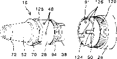
Figure 12 is the view that is similar to Fig. 9, but expression is the dental rugine of fourth embodiment of the invention;
Figure 13 is the axonometric chart of the dental rugine of Figure 12, and the main body of expression protecgulum and shell is separated;
Figure 14 is the view that is similar to Figure 11, but expression is that the vibrator module of the dental rugine of Figure 13 is in the state that is installed on the shell and pulls down from shell;
Figure 15 is the amplification view along the XV-XV line of Figure 13;
Figure 16 is the side view of partly cut-away of the pneumatic dental rugine of another embodiment of the present invention; And
Figure 17 is the side view of partly cut-away of the pneumatic dental rugine of another embodiment of the present invention.
The specific embodiment
In Fig. 1-6C, show the hand-held pneumatic dental rugine of first embodiment of the invention.
Referring to these accompanying drawings, dental rugine 10 is designed to the form of dental handpiece, and it is suitable for being connected in a dental treatment device (not shown) by a dentistry flexible pipe 12, so that obtain compressed air and water therefrom.
Be clearly shown that as Fig. 2 and 6A the axial length of protecgulum 22 equals half of vibrator module 16 substantially.Therefore, when vibrator module 16 is installed on protecgulum 22, have only the first half of vibrator module 16 to be contained in the protecgulum 22, the latter half of module is exposed to outside the protecgulum 22, shown in Fig. 6 B.
As amplifying expression among Fig. 3, vibrator module 16 comprises the metal shell 28 of a stepped drum forms, it has an axial hole 30, wherein order is equipped with discous first side plate, 32, one a jet ring 34 and discous second side plate 36, and these parts 32,34 and 36 are held on together by a maintenance screw 38 of twisting in housing 28.
Limit a discous operating room or rotor chamber 40 by the inner surface of side plate 32 and 36 and the inner peripheral surface of jet ring 34, this operating room 40 can hold a rotor or a vibrating elements 42 that is disc format with holes quiveringly.The external diameter of this vibrating elements or rotor 42 and axial width are chosen to be slightly less than the internal diameter and the axial dimension of operating room 40 respectively, to allow vibrating elements 42 vibration or vibration take place in operating room 40.
In order to improve wearability, side plate 32 and 36 and rotor 42 preferably make by the carbide alloy such as high-speed steel, and through suitable surperficial cure process.
Wish to make the size of vibrating elements 42 as much as possible little, so that vibrator is worked being higher than under the frequency of vibration 15000 hertz, near ultrasonic wave range.A preferable axial width of vibrating elements or rotor 42 is about the 0.4-0.8 millimeter, and an one preferable external diameter is about the 5-8 millimeter.
For compressed air delivery is arrived nozzle 44, the housing 28 of vibrator module 16 has a groove 46 that along the circumferential direction extends along it in the face of inner peripheral surface of nozzle 44, this groove and then communicate with a plurality of air intakes 48 (also referring to Fig. 6 C) that carry out that along the circumferential direction separate each other.Compressed air delivery is described in the back to the mode of these inlets 48.
In order in odontexesis operation, to supply with cooling and to clean the water of odontexesis head 18 and tooth, a flow pipe 50 is set, it extends through housing 28, side plate 32 and 36 and the central opening that keeps screw 38 respectively.Vibrating elements 42 also has a central opening, is not subjected to the interference of water pipe 50 with the vibration of guaranteeing vibrating elements.
The front opening of water pipe 50 is gone in the internal thread hole 54 (Fig. 3) that is formed in the smaller diameter end shaft portion 52 of housing 28, the external screw thread coupling part 53 (Fig. 1) that odontexesis head 18 is installed with screw thread.Water pipe 50 and housing 28 seal each other by one or more O shape ring 56 (Fig. 3).
In order to prevent that vibrating elements 42 from adhering to the inner surface of side plate 32 and 36 unfriendly when vibrator is not worked, pressing has a pair of axle sleeve 58 and 60 in the centre bore of side plate 32 and 36, and their axial length is slightly larger than the axial width of side plate.The details of axle sleeve is at US-A-5, description arranged in 997,172, and the announcement of this patent is quoted at this for reference.
The used air inner space by axle sleeve 60 and keep the central opening 62 of screw 38 to discharge also in operating room 40, opening 62 thereby also as an air vent.
As the clearest expression among Fig. 3, the axially extended stepped hole 27 of protecgulum 22 has backwards a location shoulder, and vibrator housing 28 correspondingly has a location shoulder 66 relative with this shoulder 64.One O shape ring 70 is installed in the groove 68 outside formed one on housing 28.By a location sleeve 90 vibrator module 16 is pressed against protecgulum 22, O shape ring 70 suitably is pressed between shoulder 64 and 66, thereby can makes vibrator module 16 with respect to protecgulum 22 axial location.
Anti-rotation structure must be set, prevent that with formed screwed hole 54 in the end axle 52 of the housing 28 that odontexesis head 18 is screwed to module 16 or when wherein back-outing vibrator module 16 from respect to shell 14 disadvantageous rotation taking place.In first embodiment, housing 28 is locked in protecgulum 22 on rotating.For this reason, shown in Fig. 3 and 5, one mid portion 76 with elliptic cross-section is set between the major diameter part 74 of end axle 52 and housing 28, the shape of the inner peripheral surface 77 of protecgulum 22 is made has a complementary with it elliptic cross-section, side with the oval part 76 of guaranteeing rot housing 28 contacts with the inner peripheral surface 77 of protecgulum 22, thereby restriction housing 28 is with respect to the rotation of protecgulum 22.One elastomer O shape ring 80 can be installed in the outer groove 78 of oval part 76, be delivered to protecgulum 22 by this part 76 with the vibration that prevents module 16.
Referring to Fig. 1 and 2, dental rugine 10 is attached, in a conventional manner, to the dentistry flexible pipe 12 that extends out from a dental treatment device (not shown).For this reason, first parts 82 (for example being common unit) of a traditional hose coupling are connected in an end of dentistry flexible pipe 12, and second parts 84 (for example being auxiliary assembly) are arranged on the rear end of the main body 26 of shell 14.In the embodiment shown in Fig. 1 and 2, first connector on the flexible pipe 12 is the form of plug 82, and this plug has the ball lock type quick-connect machanism 85 of a plug, and second connector on the shell 14 is the form of socket 84, this socket has a joint shape hole 86, wherein plugs plug 82.Socket piece 84 is snugly inserted main body 26, and remains on the appropriate location by a maintenance screw 88 that is screwed into main body 26.
The front end of abutment sleeve 90 is the front end of the main body 26 of retraction shell 14 backward.Therefore, form the chamber 91 of open front on one day in the main body 26 between the front end of the front end of main body 26 and abutment sleeve 90.This chamber 91 matches with the stepped axial hole 27 of protecgulum 22 and forms a room 92 that is used to hold vibrator module 16.
On the other hand, annular space 93 communicates with the plug receiving opening 86 of socket 84 by an air duct 96 (Fig. 2) that is formed in the socket 84 of hose coupling, and will communicate with the air supply opening 98 of plug 82 when the plug 82 of hose coupling inserts sockets 84.In addition, annular space 93 communicates with the air intake 48 of vibrator housing 28, thus compressed air by enter the mouth 48 and the inner groovy 46 of housing 28 be transported to the nozzle 44 of jet ring 34.
Exhausted air will send back to dentistry flexible pipe 12 by formed jet channel 102 on the socket 84 of annular space 100 between the central opening 62 (Fig. 2), abutment sleeve 90 and the water pipe 50 that keep screw 38 and hose coupling in the operating room 40.
Cooling and rinse water can be formed at the center aquaporin (not shown) in the plug 82 of hose coupling and be transported to an aquaporin 104 (Fig. 1) that is formed in the odontexesis head 18 by water pipe 50 in a conventional manner by one, thereby flow to odontexesis head 18.The rear end of water pipe 50 is supported securely by socket 84.
In use, odontexesis head 18 is screwed in the screwed hole 54 of vibrator module 16 securely, and the plug 82 of dentistry flexible pipe 12 is inserted the socket 84 of the hose coupling of shells 14 with a spanner, in order to compressed air delivery to vibrator.When compressed air tangentially sprays into operating room 40 by nozzle 44, in operating room 40, produce an eddy airstream, thereby press US-A-4, the principle described in 453,919 makes vibrating elements 42 vibrations, thereby produces vibration.Press US-A-5, the principle described in 190,456, the transfer of vibration that vibrator module 16 is produced be to odontexesis head 18, thereby make it with the high frequency of vibration vibration near ultrasonic wave range.
When using dental rugine 10, vibrating elements 42 and side plate 32 and 36 can wear and tear, thereby reduce the power output of vibrator 16.That kind, the user can entirely change vibrator module 16 easily in the following manner.
At first, twist with a suitable spanner and send odontexesis head 18 and it is pulled down from vibrator module 16.Then, user grips the protecgulum 22 and the main body 26 of shell 14 and turns on protecgulum 22 and main body 26 with two handss respectively, separates with main body 26 up to protecgulum 22, as shown in Figure 6A.
Because vibrator module 16 is locked in protecgulum 22 by anti-rotation structure 76/77 rotating, thereby when protecgulum 22 and main body 26 are turned on each other, water pipe 50 will be drawn out O shape ring 56 when rotating with respect to O shape ring 56.Therefore, there is sliding friction at the contact point place between water pipe 50 and O shape ring 56.On the contrary, there is static friction at the contact point place between protecgulum 22 and O shape ring 70 and 72, and this static friction is greater than the sliding friction that puts between water pipe 50 and the O shape ring 56.
Therefore, when protecgulum 22 separated with main body 26, vibrator module 16 encircled reason O shape 70 and 72 static friction and keeps being connected in protecgulum 22, as shown in Figure 6A.At this moment, half of vibrator module 16 will be exposed to outside the protecgulum 22 backwards.This visually will encourage the user to come to change with one new to vibrator module 16.Because outside the latter half of vibrator module 16 was exposed to, it can grip with finger at an easy rate.
Therefore, grip protecgulum 22, grip vibrator module 16 with the finger of another hands, and shown in Fig. 6 B, draw back protecgulum and module with the finger of a hands, just vibrator module 16 is separated with protecgulum 22, shown in Fig. 6 C.
Afterwards, only need a new vibrator module is installed on protecgulum 22, and protecgulum 22 is threaded each other with main body 26, like this, in case install odontexesis head 18, odontexesis head 10 just can be once more for having used.
In this way, according to the present invention, when reducing in the wearing and tearing of the efficient cause vibrating elements of discovering vibrator and associated components, anyone can change vibrator module at an easy rate, and need not to seek help from special anchor clamps or instrument.Can dispose or deliver to the maintenance center with old vibrator module.
Fig. 7 and 8 shows a kind of version of implementing dental rugine of the present invention.This version only is with the different of first embodiment, replaces employed ball lock type quick-connect machanism among first embodiment with a traditional screw-type hose coupling.Therefore, represent with identical label in Fig. 7 and 8 with similar those parts of first embodiment, and no longer be repeated in this description.
With reference to Fig. 7 and 8 and only describe its difference, male connector 84A that are embedded in the main body 26 of shell 14 have external screw thread 106, and the female thread (not shown) that this external screw thread is used on the female connector 82A with hose coupling engages.Female connector 82A for example can be a kind of four traditional cellular type standard components.
In use, male connector 84A and female connector 82A twisted close in together, thereby the dental rugine of this version is connected in dentistry flexible pipe 12.In others, the operation of this dental rugine and the substitute mode of vibrator module are all described identical with first embodiment.
Fig. 9-11 shows the dental rugine of third embodiment of the invention.The characteristics of this embodiment are that vibrator module 16 is locked in main body 26 on rotating.In Fig. 9-11, represent with identical label with similar those parts of first embodiment, and no longer be repeated in this description.
Its difference is only described, before being used for detachably connecting this 22 and the nipple of main body 26 comprise that one is formed at external screw thread 120 and on the anterior outer peripheral face of main body 26 and is formed at female thread 122 on the rear portion inner rim of protecgulum 22.
In this embodiment, because the connecting thread 120 of main body 26 is formed at the outside of main body 26, thereby the forward chamber 91 of main body 26 has inner peripheral surface 124 one columnar, no any screw thread.This just allows the inner peripheral surface 124 of forward chamber 91 can have a plurality of notches or caves in 126, and quantity is six for example, and they along the circumferential direction equidistantly separate each other.Central notch 126 for example can be by carrying out local milling or boring to the inner peripheral surface of chamber 91 and forming at an easy rate vertically.
Corresponding with formed notch on the inner peripheral surface 124 of main body 26 126, between the housing 28 of vibrator module 16 and end axle 52, form a locking mechanism 128 that is hexagonal cross-section, the end axle among this embodiment is tapered, to strengthen the transmission of acoustical vibration.The sectional dimension of locking mechanism 128 is chosen to make each dihedral of hexagonal cross-section to be engaged in loosely respectively in each notch 126.
In order to change vibrator module 16, at first, grip main body 26 securely with a hands, unscrew odontexesis head 18 with a spanner simultaneously, thereby odontexesis head 18 is separated with vibrator module 16.Opposite with first embodiment, because the vibrator module 16 among this embodiment is locked in main body 26 by anti-rotation structure 126/128, thereby protecgulum 22 can not be subjected to the torsional interaction that spanner applies.This can prevent to unclamp accidentally protecgulum 22 when unscrewing odontexesis head 18.
Then, turn on the screw thread 122 of protecgulum 22 and the screw thread 120 of main body 26, make protecgulum 22 and main body 26 separated from one another with hands.
In the 3rd embodiment, because vibrator module 16 is locked in main body 26 on rotating, as previously described, thereby there is static friction in the contact point place between water pipe 50 and O shape ring 56, and the contact point that encircles between 70 and 72 protecgulum 22 and O shape when protecgulum 22 and main body 26 are turned on each other will produce sliding friction.Therefore, when protecgulum 22 separated with main body 26, vibrator module 16 was connected in main body 26 with maintenance, as shown in figure 10.
Therefore, hold main body 26 with the finger alunite of a hands, the finger of another hands grips vibrator module 16, and main body 26 and module 16 are drawn back, and vibrator module 16 is separated, as shown in figure 11 with main body 26.
In the time a new vibrator module need being installed on dental rugine 10, earlier vibrator module 16 is rotated with respect to main body 26, be embedded in respectively in the notch 126 up to each angle of hexagon locking mechanism 128, thereby module is located on angle, then, module 16 partly is pressed into main body 26.As can be seen from Figure 11,, thereby at most only need relatively rotate 60 degree angles, just can at an easy rate vibrator module 16 be assembled on the main body 26 because locking mechanism 128 has a hexagonal cross section.
Then, protecgulum 22 is screwed on the main body 26, and odontexesis head 18 is threadedly connected to vibrator module 16 with a spanner.In the process of tightening odontexesis head 18, the moment of torsion that is applied by spanner will be born by main body 26, thereby protecgulum 22 can not be subjected to the effect of the screw-down torque that spanner applies.This can prevent advantageously that just protecgulum 22 is by overtorquing.Therefore, can unclamp protecgulum 22 at an easy rate at the time standby hands of needs.
Figure 12-15 shows the dental rugine of fourth embodiment of the invention.Those parts identical with previous embodiment are represented with identical label, and no longer are repeated in this description.The module of using among vibrator module 16 among this embodiment and the embodiment shown in Fig. 9-11 is identical.
The characteristics of this embodiment are, compare with the 3rd embodiment, and protecgulum makes long significantly, and slightly more carefully.For this reason, structure is made like this, that is, vibrator module 16 is locked in abutment sleeve on rotating.
More particularly, referring to Figure 12-15, the axial length of protecgulum 22A is greater than half of the whole axial length of head 10.The main body 26A of shell correspondingly shortens.Therefore, the contact space of prominence between main body 26A and the protecgulum 22A is in the rear of the front end of abutment sleeve 90A.
For anti-rotation locking vibrator module, use abutment sleeve 90A, this can make protecgulum 22A longer, thereby removes the nipple 20/24 and 120/122 of previous embodiment in the zone that is located immediately at vibrator module 16 radially outers of head.So just allow to reduce as much as possible the protecgulum external diameter that user's finger in the dental treatment process grips the position.This can be convenient to user significantly and snugly grip head to being less than about 1 millimeter though the possible decrease of protecgulum external diameter is little, and when treatment dental tool is accurately located with respect to tooth.
In this embodiment, protecgulum 22A and main body 26A detachably are connected to each other by employed nipple 120/122 among a fast joint structure rather than the 3rd embodiment.Like this, as shown in figure 15, in the formed radial hole 140 a telescopic locking pin 138 is installed slidably in a connection insert 142, this connection insert closely is embedded in the housing main body 26A.Lock pin 138 is by a disc spring 144 radial outward bias voltages, so that engage with a formed through hole 146 among the protecgulum 22A.
In use, protecgulum 22A and main body 26A are connected to each other by the lock pin 138 that is engaged in the respective aperture 146.Owing to vibrator module 16 is locked in abutment sleeve 90A on rotating by anti-rotation structure 128/134/136, therefore, in order odontexesis head 18 to be screwed on the vibrator module 16 and to back out and the moment of torsion that put on the odontexesis head by spanner will be passed to abutment sleeve 90A earlier, and be passed to protecgulum 22A by lock pin 138 therefrom from module.Be easy to grip owing to protecgulum makes long enough, thereby the moment of torsion that spanner applied will complete bearing by secure grip protecgulum 22A.
In order to change vibrator module 16, earlier odontexesis head 18 is pulled down from vibrator module 16, and lock pin 138 inwardly pushed away and break away from hole 146.When protecgulum 22A separated with main body 26A, vibrator module 16 was connected in housing 134 with maintenance, as shown in figure 13.Obviously, just be easy to now with point grip module 16 and change with one new, as shown in figure 14.
In the process of daily use head, preferably protecgulum 22A is pulled down and only protecgulum cleaned with autoclave sterilization with the ultrasonic purification device from head.Because protecgulum covers most of length of head, thereby only need continually protecgulum to be carried out disinfection and purify just to keep head to clean substantially and health.Only protecgulum being carried out disinfection helps preventing the other parts generation thermal degradation of vibrator module and head, thereby prolongs the service life of these members.
Figure 16 and 17 shows other embodiments of the invention.Equally, represent with identical label with the similar parts of previous embodiment.
In the embodiment shown in Figure 16, the protecgulum 22A that forms the part shell detachably is connected by nipple 148 each other with main body 26B, and locks each other by a lock-screw 150.This lock-screw 150 can prevent advantageously that protecgulum 22A and main body 26B from undesirable unclamping being taken place when high-head being screwed on the vibrator module 16.
In the embodiment shown in Figure 17, protecgulum 22B makes long enough, with the whole length of basic covering head, thereby is convenient to sterilize and improves the gripping of hands, as previously mentioned.Protecgulum 22B also can be used for hiding the adjustment screw 152 and 154 of the flow control valve of the control compressed air adorned among the main body 26B and cooling water flow.Also with lock pin 138 protecgulum 22B and main body 26B are connected to each other in case configure adjustment screw 152 and 154, protecgulum 22B just can prevent to touch accidentally adjustment screw 152 and 154.
Though invention has been described with reference to its specific embodiment here, the present invention is not limited, and those skilled in the art can carry out various variation and modification to it and not depart from the scope of the present invention.For example, Pneumatic dental utensil of the present invention can be used for the occasion of any needs except that dental rugine.The structure, form and the quantity that constitute the element of rotation-preventing mechanism can change.Specifically, hexagonal structure can be made into triangle, tetragon or pentagonal configuration, or sell by one or more and to replace.
Claims (19)
1. Pneumatic dental vibrator tool comprises:
One elongate housing, it has one and is defined as room successive with described shell front end, longitudinal extension, and described shell is divided into a main body and a protecgulum, and they detachably connect each other;
One is contained in the pneumatic vibrator module in the described room replaceably, and described module has a vibrative vibrating elements, and described module has a vibration tool detachably is connected in the forward screw connection of described module;
With the device of described module elastic bearing in described shell;
Make described vibrator module against the localized axial direction positioning device of described protecgulum;
Give described vibrator module to encourage the device of described vibrating elements compressed air delivery; And
When being screwed to described vibration tool on the described vibrator module or backing out from it, prevent the anti-rotation device that described vibrator module rotates with respect to described shell, it is characterized in that, the axial location of the contact between described main body and the described protecgulum is chosen to like this, promptly, when described main body and described protecgulum separated from one another so that when changing described vibrator module, at least a portion of described vibrator module is exposed to outside the described main body or protecgulum that it connects, and grips the residence and states module and described module is taken out from described main body or protecgulum with pointing to allow the operator.
2. vibration apparatus as claimed in claim 1, it is characterized in that, described rotation-preventing mechanism is suitable for described vibrator module is locked in described protecgulum, make when main body and protecgulum are separated from one another, vibrator module trend keeps being connected in protecgulum, and the axial length of protecgulum makes the axial length that is shorter than vibrator module, to guarantee when main body and protecgulum are separated from one another, the rear portion of vibrator module is exposed to outside the protecgulum, thereby the permission operator grips the described rear portion of module and it is taken out from protecgulum.
3. vibration apparatus as claimed in claim 2, it is characterized in that, the axial length of protecgulum equals half of axial length of vibrator module substantially, to guarantee that the latter half of vibrator module is exposed to outside the protecgulum so that the operator grips when main body and protecgulum are separated from one another.
4. vibration apparatus as claimed in claim 1, it is characterized in that, described rotation-preventing mechanism is suitable for described vibrator module is locked in described main body, make when main body and protecgulum are separated from one another, vibrator module trend keeps being connected in main body, and the axial length of protecgulum makes the axial length that is shorter than vibrator module, to guarantee when main body and protecgulum are separated from one another, the front portion of vibrator module is exposed to outside the main body, thereby the permission operator grips the described front portion of module and it is taken out from main body.
5. vibration apparatus as claimed in claim 4, it is characterized in that, the axial length of protecgulum equals half of axial length of vibrator module substantially, and guaranteeing when main body and protecgulum are separated from one another, the first half of vibrator module is exposed to outside the main body so that the operator grips.
6. as claim 4 or 5 described vibration apparatus, it is characterized in that, the described anti-rotation device that vibrator module is locked in main body also is suitable for guaranteeing for described vibration tool being screwed on the vibrator module or backing out the moment of torsion that puts on described vibration tool from vibrator module and born by main body, thereby protecgulum is not subjected to described torsional interaction.
7. as the described vibration apparatus of claim 4-6, it is characterized in that described rotation-preventing mechanism comprises at least one notch of being formed on the main body inner peripheral surface and is arranged on the vibrator module outer peripheral face and at least one corresponding projection of matching with described notch.
8. vibration apparatus as claimed in claim 7 is characterized in that, described anti-rotation device comprises that one is arranged on the structure of the polygonal cross-section on the outer peripheral face of vibrator module.
9. vibration apparatus as claimed in claim 8 is characterized in that described structure has hexagonal cross-section.
10. vibration apparatus as claimed in claim 1, it is characterized in that, described axial direction positioning device comprises that one extends axially in described shell and is fixed in the abutment sleeve of described main body, described rotation-preventing mechanism is suitable for vibrator module is locked in described abutment sleeve, make protecgulum and body portion from the time, the vibrator module trend keeps being connected in abutment sleeve, contact between main body and the protecgulum is positioned at the rear of abutment sleeve front end, when main body and protecgulum are separated from one another, guaranteeing that the front portion of vibrator module is exposed to outside the abutment sleeve, thereby allow the operator to grip the described front portion of module and module is taken out from the abutment sleeve that it connected.
11. vibration apparatus as claimed in claim 10 is characterized in that, the axial length of protecgulum is greater than half of the whole axial length of shell.
12. vibration apparatus as claimed in claim 11 is characterized in that, the protecgulum long enough is with the whole length of basic covering utensil.
13. each the described vibration apparatus as claim 10-12 is characterized in that main body detachably is connected by nipple each other with protecgulum.
14. vibration apparatus as claimed in claim 13 is characterized in that, it comprises that also one is locked in the lock-screw of main body with protecgulum.
15. each the described vibration apparatus as claim 10-12 is characterized in that, main body and protecgulum detachably are connected each other by a telescopic lock pin.
16. each described vibration apparatus as claim 10-15, it is characterized in that described anti-rotation device comprises at least one projection on the outer peripheral face that is arranged on vibrator module and a holding element that matches with described projection with abutment sleeve formation one.
17. vibration apparatus as claimed in claim 16, it is characterized in that, described anti-rotation device comprises the structure of the polygonal cross-section on the outer peripheral face that is formed at vibrator module, and described holding element has a plurality of depressions, and each dihedral of described polygonized structure is engaged in respectively in the described depression.
18. vibration apparatus as claimed in claim 17 is characterized in that, described structure has hexagonal cross-section.
19. a pneumatic dental rugine, it has an odontexesis head, and this odontexesis head is installed on the vibrator module of the described vibration apparatus of above each claim.
Applications Claiming Priority (4)
| Application Number | Priority Date | Filing Date | Title |
|---|---|---|---|
| JP2001050339 | 2001-02-26 | ||
| JP50339/01 | 2001-02-26 | ||
| JP2001194494 | 2001-06-27 | ||
| JP194494/01 | 2001-06-27 |
Publications (2)
| Publication Number | Publication Date |
|---|---|
| CN1371663A true CN1371663A (en) | 2002-10-02 |
| CN1232230C CN1232230C (en) | 2005-12-21 |
Family
ID=26610094
Family Applications (1)
| Application Number | Title | Priority Date | Filing Date |
|---|---|---|---|
| CNB021053774A Expired - Lifetime CN1232230C (en) | 2001-02-26 | 2002-02-26 | Pneumatic dental vibrator with replaceable vibrator module |
Country Status (5)
| Country | Link |
|---|---|
| US (1) | US6752629B2 (en) |
| EP (1) | EP1234551B1 (en) |
| CN (1) | CN1232230C (en) |
| AT (1) | ATE303106T1 (en) |
| DE (1) | DE60205787T2 (en) |
Cited By (6)
| Publication number | Priority date | Publication date | Assignee | Title |
|---|---|---|---|---|
| US9387051B2 (en) | 2011-05-13 | 2016-07-12 | Propel Orthodontics, Llc | Method and device for causing tooth movement |
| USD761963S1 (en) | 2014-07-29 | 2016-07-19 | Propel Orthodontics, Llc | Microperforation dental device |
| US9687323B2 (en) | 2012-06-07 | 2017-06-27 | Propel Orthodontics, Llc | Temporary anchorage device with external plate |
| CN112338858A (en) * | 2020-12-03 | 2021-02-09 | 刘明青 | Dental low-speed mobile phone disassembling device |
| CN114345677A (en) * | 2021-10-29 | 2022-04-15 | 中国航发西安动力控制科技有限公司 | Valve sleeve type pneumatic vibrator |
| WO2022198781A1 (en) * | 2021-03-22 | 2022-09-29 | 桂林市啄木鸟医疗器械有限公司 | Air pressure adjustment structure |
Families Citing this family (17)
| Publication number | Priority date | Publication date | Assignee | Title |
|---|---|---|---|---|
| US7310811B1 (en) * | 1997-07-15 | 2007-12-18 | At&T Corp. | Interaction modalities for multimedia delivery and presentation |
| EP1441659A1 (en) * | 2001-10-17 | 2004-08-04 | Dentsply International, Inc. | Unitized modular ultrasonic handpiece cable connector |
| US20050142515A1 (en) * | 2002-12-12 | 2005-06-30 | Hiam Levy | Dental tool having a hand grip |
| BRPI0515652A (en) * | 2004-09-21 | 2008-07-29 | Discus Dental Impressions Inc | dental tool |
| US8388523B2 (en) | 2005-04-01 | 2013-03-05 | Welch Allyn, Inc. | Medical diagnostic instrument having portable illuminator |
| AU2006232534B2 (en) | 2005-04-01 | 2011-10-06 | Welch Allyn, Inc. | Vaginal speculum |
| US7959438B2 (en) * | 2005-08-11 | 2011-06-14 | James Feine | Movable pin ultrasonic transducer |
| US8142352B2 (en) | 2006-04-03 | 2012-03-27 | Welch Allyn, Inc. | Vaginal speculum assembly having portable illuminator |
| US8641417B2 (en) * | 2008-10-29 | 2014-02-04 | Arthrex, Inc. | Sealing system for medical/dental handpieces |
| US9788925B2 (en) * | 2009-08-19 | 2017-10-17 | Vicky L Moran | Transducer activated tool with water conduit |
| US9452027B2 (en) * | 2009-12-10 | 2016-09-27 | Kerrhawe Sa | Dental composite applicator and related methods |
| CN104039264A (en) * | 2011-12-23 | 2014-09-10 | 埃尔斯盖恩产品私人有限公司 | A Dental Hygiene Item |
| KR101624214B1 (en) | 2013-02-19 | 2016-05-25 | 에프에스 테크니칼 코포레이션 | Diameter-expanding drill bit |
| US9532706B2 (en) | 2014-08-07 | 2017-01-03 | Welch Allyn, Inc. | Vaginal speculum with illuminator |
| CN106618774A (en) * | 2016-11-29 | 2017-05-10 | 桂林市啄木鸟医疗器械有限公司 | Novel luminous ultrasonic tooth cleaner handle and processing technology thereof |
| CN106491229A (en) * | 2016-11-30 | 2017-03-15 | 桂林市啄木鸟医疗器械有限公司 | A kind of new transducer and the handle containing which |
| CN106491230A (en) * | 2016-12-05 | 2017-03-15 | 桂林市啄木鸟医疗器械有限公司 | A kind of new ultrasonic dental scaler transducer and the tooth cleaner handgrip containing which |
Family Cites Families (11)
| Publication number | Priority date | Publication date | Assignee | Title |
|---|---|---|---|---|
| US3444622A (en) * | 1965-06-07 | 1969-05-20 | Tonk Mills | Air operated vibrator for dentistry |
| US3654502A (en) * | 1970-06-24 | 1972-04-04 | Countronic Corp | Ultrasonic tool |
| US3811190A (en) | 1973-05-29 | 1974-05-21 | A Sertich | Air-vibrator dental scaler |
| US3956826A (en) | 1974-03-19 | 1976-05-18 | Cavitron Corporation | Ultrasonic device and method |
| US4453919A (en) | 1981-04-24 | 1984-06-12 | Micron Co., Ltd. | Dental scaler |
| DE3328603A1 (en) | 1983-08-08 | 1985-02-28 | Kaltenbach & Voigt Gmbh & Co, 7950 Biberach | Tartar removal handpiece |
| US5190456A (en) | 1986-09-26 | 1993-03-02 | Micron Co., Ltd. | Air-driven dental scaler |
| US5232363A (en) * | 1991-06-11 | 1993-08-03 | Eran Meller | Scaler with improved vibration characteristics |
| SE502270C2 (en) * | 1994-01-28 | 1995-09-25 | Amdent Ab | Dental device with a working tool coupled with a protective sleeve |
| US5501596A (en) * | 1994-07-27 | 1996-03-26 | Young Dental Manufacturing Company, Inc. | Autoclavable dental scaler handpiece |
| JP3712829B2 (en) * | 1997-05-15 | 2005-11-02 | 株式会社ミクロン | Pneumatic vibrator |
-
2002
- 2002-01-30 US US10/058,975 patent/US6752629B2/en not_active Expired - Lifetime
- 2002-02-15 EP EP02003600A patent/EP1234551B1/en not_active Expired - Lifetime
- 2002-02-15 AT AT02003600T patent/ATE303106T1/en active
- 2002-02-15 DE DE60205787T patent/DE60205787T2/en not_active Expired - Lifetime
- 2002-02-26 CN CNB021053774A patent/CN1232230C/en not_active Expired - Lifetime
Cited By (8)
| Publication number | Priority date | Publication date | Assignee | Title |
|---|---|---|---|---|
| US9387051B2 (en) | 2011-05-13 | 2016-07-12 | Propel Orthodontics, Llc | Method and device for causing tooth movement |
| US9814547B2 (en) | 2011-05-13 | 2017-11-14 | Propel Orthodontics, Llc | Method and device for causing tooth movement |
| US10245122B2 (en) | 2011-05-13 | 2019-04-02 | Advanced Orthodontics And Education Association, Llc | Method and device for causing tooth movement |
| US9687323B2 (en) | 2012-06-07 | 2017-06-27 | Propel Orthodontics, Llc | Temporary anchorage device with external plate |
| USD761963S1 (en) | 2014-07-29 | 2016-07-19 | Propel Orthodontics, Llc | Microperforation dental device |
| CN112338858A (en) * | 2020-12-03 | 2021-02-09 | 刘明青 | Dental low-speed mobile phone disassembling device |
| WO2022198781A1 (en) * | 2021-03-22 | 2022-09-29 | 桂林市啄木鸟医疗器械有限公司 | Air pressure adjustment structure |
| CN114345677A (en) * | 2021-10-29 | 2022-04-15 | 中国航发西安动力控制科技有限公司 | Valve sleeve type pneumatic vibrator |
Also Published As
| Publication number | Publication date |
|---|---|
| EP1234551A3 (en) | 2003-03-19 |
| CN1232230C (en) | 2005-12-21 |
| DE60205787T2 (en) | 2006-05-18 |
| EP1234551A2 (en) | 2002-08-28 |
| US20020119419A1 (en) | 2002-08-29 |
| ATE303106T1 (en) | 2005-09-15 |
| US6752629B2 (en) | 2004-06-22 |
| DE60205787D1 (en) | 2005-10-06 |
| EP1234551B1 (en) | 2005-08-31 |
Similar Documents
| Publication | Publication Date | Title |
|---|---|---|
| CN1232230C (en) | Pneumatic dental vibrator with replaceable vibrator module | |
| JP2019501736A (en) | electric toothbrush | |
| US6421865B1 (en) | Electric toothbrush | |
| US6716028B2 (en) | Ultrasonic swivel insert | |
| TWI554253B (en) | A vibratory instrument with an interchangeable tool | |
| US20050136375A1 (en) | Method and apparatus to remove macro and micro debris from a root canal | |
| CN112353510A (en) | Root canal treatment equipment | |
| JP2002113019A (en) | Instrument for medical or dental use having pneumatic vibration drive mechanism, especially | |
| US20090017414A1 (en) | Dental Handpiece | |
| CN102715964B (en) | Sonic electric vibrating toothbrush | |
| CN114641254A (en) | Endodontic treatment handpiece systems and methods | |
| CN101031251A (en) | Dental instruments | |
| JP4048264B2 (en) | Pneumatic dental vibrator with easily replaceable vibrator | |
| JPS6399855A (en) | Air drive type dental tartar removing apparatus | |
| US20230066307A1 (en) | Tool for a medical treatment, tool tip, moving part and/or handpiece for such a tool and method for producing such a tool for a medical treatment | |
| JP2004351104A (en) | Dental scaler | |
| JP4168420B2 (en) | Pneumatic dental vibration handpiece with easily replaceable vibrator | |
| JPH07116018A (en) | Toothbrush and motor-driven toothbrush | |
| CN214049137U (en) | Root canal treatment equipment | |
| EP4356866A1 (en) | A tip holder, a tool tip and a medical tool | |
| CN113425432B (en) | Peri-implant inflammation treatment device capable of promoting bone union | |
| CN216535612U (en) | Connection structure and scaler | |
| JP6349526B2 (en) | Method of manufacturing brush holder for dental vibratory handpiece | |
| WO2024083763A1 (en) | A tip holder, a tool tip and a medical tool | |
| JP2021090689A (en) | Tip mounting screw of ultrasonic handpiece |
Legal Events
| Date | Code | Title | Description |
|---|---|---|---|
| C10 | Entry into substantive examination | ||
| SE01 | Entry into force of request for substantive examination | ||
| C06 | Publication | ||
| PB01 | Publication | ||
| C10 | Entry into substantive examination | ||
| SE01 | Entry into force of request for substantive examination | ||
| C14 | Grant of patent or utility model | ||
| GR01 | Patent grant | ||
| CX01 | Expiry of patent term |
Granted publication date: 20051221 |
|
| CX01 | Expiry of patent term |