CN1458855B - Air filtration arrangements having fluted media constructions and filter method - Google Patents
Air filtration arrangements having fluted media constructions and filter method Download PDFInfo
- Publication number
- CN1458855B CN1458855B CN018151671A CN01815167A CN1458855B CN 1458855 B CN1458855 B CN 1458855B CN 018151671 A CN018151671 A CN 018151671A CN 01815167 A CN01815167 A CN 01815167A CN 1458855 B CN1458855 B CN 1458855B
- Authority
- CN
- China
- Prior art keywords
- air
- filter
- filter element
- polymer
- media set
- Prior art date
- Legal status (The legal status is an assumption and is not a legal conclusion. Google has not performed a legal analysis and makes no representation as to the accuracy of the status listed.)
- Expired - Lifetime
Links
Images


Classifications
-
- D—TEXTILES; PAPER
- D01—NATURAL OR MAN-MADE THREADS OR FIBRES; SPINNING
- D01F—CHEMICAL FEATURES IN THE MANUFACTURE OF ARTIFICIAL FILAMENTS, THREADS, FIBRES, BRISTLES OR RIBBONS; APPARATUS SPECIALLY ADAPTED FOR THE MANUFACTURE OF CARBON FILAMENTS
- D01F6/00—Monocomponent artificial filaments or the like of synthetic polymers; Manufacture thereof
- D01F6/88—Monocomponent artificial filaments or the like of synthetic polymers; Manufacture thereof from mixtures of polycondensation products as major constituent with other polymers or low-molecular-weight compounds
- D01F6/92—Monocomponent artificial filaments or the like of synthetic polymers; Manufacture thereof from mixtures of polycondensation products as major constituent with other polymers or low-molecular-weight compounds of polyesters
-
- B—PERFORMING OPERATIONS; TRANSPORTING
- B01—PHYSICAL OR CHEMICAL PROCESSES OR APPARATUS IN GENERAL
- B01D—SEPARATION
- B01D46/00—Filters or filtering processes specially modified for separating dispersed particles from gases or vapours
-
- B—PERFORMING OPERATIONS; TRANSPORTING
- B01—PHYSICAL OR CHEMICAL PROCESSES OR APPARATUS IN GENERAL
- B01D—SEPARATION
- B01D39/00—Filtering material for liquid or gaseous fluids
- B01D39/14—Other self-supporting filtering material ; Other filtering material
- B01D39/16—Other self-supporting filtering material ; Other filtering material of organic material, e.g. synthetic fibres
- B01D39/1607—Other self-supporting filtering material ; Other filtering material of organic material, e.g. synthetic fibres the material being fibrous
- B01D39/1623—Other self-supporting filtering material ; Other filtering material of organic material, e.g. synthetic fibres the material being fibrous of synthetic origin
-
- B—PERFORMING OPERATIONS; TRANSPORTING
- B01—PHYSICAL OR CHEMICAL PROCESSES OR APPARATUS IN GENERAL
- B01D—SEPARATION
- B01D46/00—Filters or filtering processes specially modified for separating dispersed particles from gases or vapours
- B01D46/0001—Making filtering elements
-
- B—PERFORMING OPERATIONS; TRANSPORTING
- B01—PHYSICAL OR CHEMICAL PROCESSES OR APPARATUS IN GENERAL
- B01D—SEPARATION
- B01D46/00—Filters or filtering processes specially modified for separating dispersed particles from gases or vapours
- B01D46/0002—Casings; Housings; Frame constructions
- B01D46/0005—Mounting of filtering elements within casings, housings or frames
-
- B—PERFORMING OPERATIONS; TRANSPORTING
- B01—PHYSICAL OR CHEMICAL PROCESSES OR APPARATUS IN GENERAL
- B01D—SEPARATION
- B01D46/00—Filters or filtering processes specially modified for separating dispersed particles from gases or vapours
- B01D46/10—Particle separators, e.g. dust precipitators, using filter plates, sheets or pads having plane surfaces
-
- B—PERFORMING OPERATIONS; TRANSPORTING
- B01—PHYSICAL OR CHEMICAL PROCESSES OR APPARATUS IN GENERAL
- B01D—SEPARATION
- B01D46/00—Filters or filtering processes specially modified for separating dispersed particles from gases or vapours
- B01D46/52—Particle separators, e.g. dust precipitators, using filters embodying folded corrugated or wound sheet material
- B01D46/521—Particle separators, e.g. dust precipitators, using filters embodying folded corrugated or wound sheet material using folded, pleated material
- B01D46/525—Particle separators, e.g. dust precipitators, using filters embodying folded corrugated or wound sheet material using folded, pleated material which comprises flutes
- B01D46/527—Particle separators, e.g. dust precipitators, using filters embodying folded corrugated or wound sheet material using folded, pleated material which comprises flutes in wound arrangement
-
- B—PERFORMING OPERATIONS; TRANSPORTING
- B01—PHYSICAL OR CHEMICAL PROCESSES OR APPARATUS IN GENERAL
- B01D—SEPARATION
- B01D46/00—Filters or filtering processes specially modified for separating dispersed particles from gases or vapours
- B01D46/54—Particle separators, e.g. dust precipitators, using ultra-fine filter sheets or diaphragms
- B01D46/546—Particle separators, e.g. dust precipitators, using ultra-fine filter sheets or diaphragms using nano- or microfibres
-
- B—PERFORMING OPERATIONS; TRANSPORTING
- B01—PHYSICAL OR CHEMICAL PROCESSES OR APPARATUS IN GENERAL
- B01D—SEPARATION
- B01D46/00—Filters or filtering processes specially modified for separating dispersed particles from gases or vapours
- B01D46/56—Filters or filtering processes specially modified for separating dispersed particles from gases or vapours with multiple filtering elements, characterised by their mutual disposition
- B01D46/58—Filters or filtering processes specially modified for separating dispersed particles from gases or vapours with multiple filtering elements, characterised by their mutual disposition connected in parallel
-
- D—TEXTILES; PAPER
- D01—NATURAL OR MAN-MADE THREADS OR FIBRES; SPINNING
- D01D—MECHANICAL METHODS OR APPARATUS IN THE MANUFACTURE OF ARTIFICIAL FILAMENTS, THREADS, FIBRES, BRISTLES OR RIBBONS
- D01D5/00—Formation of filaments, threads, or the like
- D01D5/0007—Electro-spinning
- D01D5/0015—Electro-spinning characterised by the initial state of the material
- D01D5/003—Electro-spinning characterised by the initial state of the material the material being a polymer solution or dispersion
- D01D5/0038—Electro-spinning characterised by the initial state of the material the material being a polymer solution or dispersion the fibre formed by solvent evaporation, i.e. dry electro-spinning
-
- D—TEXTILES; PAPER
- D01—NATURAL OR MAN-MADE THREADS OR FIBRES; SPINNING
- D01D—MECHANICAL METHODS OR APPARATUS IN THE MANUFACTURE OF ARTIFICIAL FILAMENTS, THREADS, FIBRES, BRISTLES OR RIBBONS
- D01D5/00—Formation of filaments, threads, or the like
- D01D5/0007—Electro-spinning
- D01D5/0061—Electro-spinning characterised by the electro-spinning apparatus
- D01D5/0076—Electro-spinning characterised by the electro-spinning apparatus characterised by the collecting device, e.g. drum, wheel, endless belt, plate or grid
- D01D5/0084—Coating by electro-spinning, i.e. the electro-spun fibres are not removed from the collecting device but remain integral with it, e.g. coating of prostheses
-
- D—TEXTILES; PAPER
- D01—NATURAL OR MAN-MADE THREADS OR FIBRES; SPINNING
- D01F—CHEMICAL FEATURES IN THE MANUFACTURE OF ARTIFICIAL FILAMENTS, THREADS, FIBRES, BRISTLES OR RIBBONS; APPARATUS SPECIALLY ADAPTED FOR THE MANUFACTURE OF CARBON FILAMENTS
- D01F6/00—Monocomponent artificial filaments or the like of synthetic polymers; Manufacture thereof
- D01F6/88—Monocomponent artificial filaments or the like of synthetic polymers; Manufacture thereof from mixtures of polycondensation products as major constituent with other polymers or low-molecular-weight compounds
- D01F6/90—Monocomponent artificial filaments or the like of synthetic polymers; Manufacture thereof from mixtures of polycondensation products as major constituent with other polymers or low-molecular-weight compounds of polyamides
-
- D—TEXTILES; PAPER
- D04—BRAIDING; LACE-MAKING; KNITTING; TRIMMINGS; NON-WOVEN FABRICS
- D04H—MAKING TEXTILE FABRICS, e.g. FROM FIBRES OR FILAMENTARY MATERIAL; FABRICS MADE BY SUCH PROCESSES OR APPARATUS, e.g. FELTS, NON-WOVEN FABRICS; COTTON-WOOL; WADDING ; NON-WOVEN FABRICS FROM STAPLE FIBRES, FILAMENTS OR YARNS, BONDED WITH AT LEAST ONE WEB-LIKE MATERIAL DURING THEIR CONSOLIDATION
- D04H1/00—Non-woven fabrics formed wholly or mainly of staple fibres or like relatively short fibres
- D04H1/70—Non-woven fabrics formed wholly or mainly of staple fibres or like relatively short fibres characterised by the method of forming fleeces or layers, e.g. reorientation of fibres
- D04H1/72—Non-woven fabrics formed wholly or mainly of staple fibres or like relatively short fibres characterised by the method of forming fleeces or layers, e.g. reorientation of fibres the fibres being randomly arranged
- D04H1/728—Non-woven fabrics formed wholly or mainly of staple fibres or like relatively short fibres characterised by the method of forming fleeces or layers, e.g. reorientation of fibres the fibres being randomly arranged by electro-spinning
-
- B—PERFORMING OPERATIONS; TRANSPORTING
- B01—PHYSICAL OR CHEMICAL PROCESSES OR APPARATUS IN GENERAL
- B01D—SEPARATION
- B01D2265/00—Casings, housings or mounting for filters specially adapted for separating dispersed particles from gases or vapours
- B01D2265/02—Non-permanent measures for connecting different parts of the filter
- B01D2265/028—Snap, latch or clip connecting means
-
- B—PERFORMING OPERATIONS; TRANSPORTING
- B01—PHYSICAL OR CHEMICAL PROCESSES OR APPARATUS IN GENERAL
- B01D—SEPARATION
- B01D2271/00—Sealings for filters specially adapted for separating dispersed particles from gases or vapours
- B01D2271/02—Gaskets, sealings
- B01D2271/027—Radial sealings
-
- B—PERFORMING OPERATIONS; TRANSPORTING
- B01—PHYSICAL OR CHEMICAL PROCESSES OR APPARATUS IN GENERAL
- B01D—SEPARATION
- B01D2273/00—Operation of filters specially adapted for separating dispersed particles from gases or vapours
- B01D2273/20—High temperature filtration
-
- Y—GENERAL TAGGING OF NEW TECHNOLOGICAL DEVELOPMENTS; GENERAL TAGGING OF CROSS-SECTIONAL TECHNOLOGIES SPANNING OVER SEVERAL SECTIONS OF THE IPC; TECHNICAL SUBJECTS COVERED BY FORMER USPC CROSS-REFERENCE ART COLLECTIONS [XRACs] AND DIGESTS
- Y10—TECHNICAL SUBJECTS COVERED BY FORMER USPC
- Y10S—TECHNICAL SUBJECTS COVERED BY FORMER USPC CROSS-REFERENCE ART COLLECTIONS [XRACs] AND DIGESTS
- Y10S977/00—Nanotechnology
- Y10S977/84—Manufacture, treatment, or detection of nanostructure
- Y10S977/89—Deposition of materials, e.g. coating, cvd, or ald
-
- Y—GENERAL TAGGING OF NEW TECHNOLOGICAL DEVELOPMENTS; GENERAL TAGGING OF CROSS-SECTIONAL TECHNOLOGIES SPANNING OVER SEVERAL SECTIONS OF THE IPC; TECHNICAL SUBJECTS COVERED BY FORMER USPC CROSS-REFERENCE ART COLLECTIONS [XRACs] AND DIGESTS
- Y10—TECHNICAL SUBJECTS COVERED BY FORMER USPC
- Y10S—TECHNICAL SUBJECTS COVERED BY FORMER USPC CROSS-REFERENCE ART COLLECTIONS [XRACs] AND DIGESTS
- Y10S977/00—Nanotechnology
- Y10S977/902—Specified use of nanostructure
-
- Y—GENERAL TAGGING OF NEW TECHNOLOGICAL DEVELOPMENTS; GENERAL TAGGING OF CROSS-SECTIONAL TECHNOLOGIES SPANNING OVER SEVERAL SECTIONS OF THE IPC; TECHNICAL SUBJECTS COVERED BY FORMER USPC CROSS-REFERENCE ART COLLECTIONS [XRACs] AND DIGESTS
- Y10—TECHNICAL SUBJECTS COVERED BY FORMER USPC
- Y10S—TECHNICAL SUBJECTS COVERED BY FORMER USPC CROSS-REFERENCE ART COLLECTIONS [XRACs] AND DIGESTS
- Y10S977/00—Nanotechnology
- Y10S977/963—Miscellaneous
Abstract
Filter arrangements include a barrier media in the form of fluted media treated with a deposit of fine fibers. The media is particularly advantageous in high temperature (greater than 140 to 240 DEG F) systems. Such systems may include engine systems, gas turbine systems, and fuel cell systems. Filter arrangements may take the form of media packs having a circular cross-section or a racetrack shaped cross-section, or media packs formed in a panel configuration.
Description
The application is the pct international patent application of submitting in the name of August 10 calendar year 2001 with Donaldson limited company (the said firm is u s company and resident), specify the All Countries except that the U.S., and require the U.S. Serial No.60/230 that submitted on September 5th, 2000,138 and the U.S. Serial No.09/871 that submits to May 31 calendar year 2001,590 priority.
Technical field
The present invention relates to filter and filter method thereof.More particularly, the present invention relates to be used for, for example the device of filter particulate material in the air stream from air-flow.The invention still further relates to and be used for from air-flow, removing as requested the method for particulate matter.
The present invention is the achievement that the Donalson limited company of assignee of the present invention Minnesota State Minneapolis continually develops.Present disclosure relates to and United States Patent (USP) B24, and 720,292, Des 416,308,5,613,992,4,020,783 and 5,112, the continuous technological development that 372 theme is relevant.Above-mentioned each patent also returns the Donalson limited company of Minnesota State Minneapolis to own, and the full content of each patent is with reference to being incorporated into this.
The invention still further relates to filter, this filter comprises a substrate, have above it by can be heat-resisting, the fine fiber layer that makes of the polymeric material of environmental stabilities such as moisture, reactive materials and mechanical stress.These materials can be used to form the stability with improvement and the fine fibre of intensity, as micrometer fibers and nanofiber.Along with reducing of fiber size, the prolonged property of material becomes a problem day by day.These fine fibres can be used for various uses.In a purposes, structure of filter can use this fine fibre technology to prepare.The present invention relates to polymer, polymer composition, fiber, filter, filtration device structure and filter method.Application of the present invention is particularly related to from fluid stream, for example filtering particle from air-flow and liquid (for example, non-water and water) stream.The technology of describing relates to the structure that has one or more layers fine fibre in filter medium.The size of composition and fiber will be selected in conjunction with its performance and prolonged property.
Background technology
Often be loaded with particulate matter in the air-flow.In many cases, need from air-flow, remove part or all particulate matter.For example, enter air-flow in the engine of motor vehicle or TRT, import the air-flow in the gas turbine and enter in the air-flow in the various incinerators and often comprise particulate matter.If particulate matter enters in the internal part of various devices, it can cause substantial damage to these devices.So, often need from the air-flow that engine, gas turbine, stove or other device enter, remove particles contained material.
The present invention relates to have the polymer composition that improves performance, it can be used for various uses, comprises forming fiber, micrometer fibers, nanofiber, fabric, fiber mat, permeable structure such as film, covering or film.Polymeric material of the present invention is the composition with certain physical property, and it allows the polymeric material that is various physical forms and form have metamorphic resistance to moisture, heat, air stream, chemicals and mechanical stress or impact.
In the process of making fine fiber media, used various materials to comprise glass fibre, metal, pottery and a series of polymer composition.Various fibre forming methods or technology have been used for the manufacturing of minor diameter micrometer fibers and nanofiber.A kind of method comprise make fusion or the material in the solution that will evaporate subsequently by fine, soft fur tubule or opening.Fiber also can form by using " spinning head " that generally be used for producing synthetic fibers such as nylon.The method that also known static reels off raw silk from cocoons.These technology comprise uses hypodermic needle, nozzle, capillary or active transmitter.These structures provide the liquid solution of polymer, and this solution is attracted in the collecting region by the high-voltage electrostatic field subsequently.Along with material is pulled out from transmitter and quickened by the static district, fiber becomes very thin and can form fibre structure by the solvent evaporation.
Along with requiring expection that more urgent purposes is arranged for filtering to be situated between, the material that needs performance to significantly improve bear 100-250 °F, often be 140-240 °F up to 300 high temperature, 10%-90% high flow capacity until high humility, gas and the liquid of 100%RH, and filter micron and submicron particles (about more than 0.01 to 10 micron), and from fluid stream, remove abrasiveness and non-abrasiveness and reactive and non-reacted particle.
Therefore, need in fact to provide be used for filtering have high temperature, polymeric material, micron and nano material and the filtration device structure of the performance of the improvement of high humidity, high flow capacity and described micron and submicron particles material stream.
The various air cleaners or the gas filtration apparatus that are used for removing degranulation had been developed already., generally speaking, always pursuing constantly improvement.
Summary of the invention
The design that is used for air cleaner equipment and the general technology of purposes are provided herein.These technology comprise optimum filter element design, and the best approach of purposes and filtration.
Generally speaking, best use relates to Z-shaped medium in the air cleaner, comprises the advantages of application of the compound of substrate and fine fibre.
The filter medium assembly is included in combining of at least one micron in the filtration device structure of mechanically stable or layers of nanofibers and base material.When fluid such as gas or liquid during by filter medium, these layers together provide fabulous filterability, higher particle capture performance and the efficient when minimum flow limits.Substrate can be arranged in front, back or the internal layer of fluid stream.No matter the geometry of filter how, fiber can be positioned on front, the back side or the two sides of filter base.Fiber is usually located on the front of substrate.But also can be on the back side of substrate in some purposes.In some purposes, use bilateral structure.In recent years, various commercial runs have received great concern, and for example, they use filter medium to remove by filter unwanted particle from fluid such as gas or liquid.Common filter method comprises in air stream or other gas stream or from liquid and flowing as removing degranulation hydraulic fluid, lubricating oil, fuel oil, current or other fluid from fluid.These filter methods have requirement to mechanical strength, chemistry and the physical stability of micrometer fibers and base material.This filter medium can be exposed in carry secretly in temperature conditions, humidity, mechanical oscillation and the impact of wide region and the fluid stream reactive and non-reacted, abrasiveness and the non-abrasiveness particle.During normal operation, filter is normally in room temperature or near room temperature or slightly in the air of high-temperature.When stopping working when the engine operation exception or after long-time running, filter can be in higher temperature.If engine does not move, then air does not pass through filter.Filter can reach the case temperature very soon.In addition, filter medium often filter medium need be exposed to buffer brake pulse (the short time counter-rotating of fluid stream is in order to remove the superficial layer of degranulation) effect down self-purification capacity or can be from filter medium surface other purifier except that the particle of deentrainment.After pulse purified, this counter-rotating purification can cause substantially improving and promptly reduces pressure and fall.The capture rate of particle generally can not be improved after pulse purifies, and falls but the pulse purification can reduce pressure, thereby saves the energy that is used for filter operation.In order to make these filter operations, filter medium wherein can be removed down, place water or non-water cleansing composition to clean.By extract fine fibre, make usually by the link fabric that forms micrometer fibers then in the porous substrate for this medium.In drawing process, can form physical bond between the fiber, mat of fibers is linked be complete layer.Then, this material can constitute required filter form, as tube, square position, jar, dish, bag and box.In these structures, medium can be pleating fully, roll-in or otherwise be arranged on the supporting construction.
The filter of Miao Shuing can be widely used in various uses herein, comprises getting on the car in for example dedusting, air compressor, road and offroad vehicle engine, gas turbine engine systems, generator such as fuel cell and other.
The invention provides a kind of filter element device, it comprises:
A media set, it comprises substrate and many grooves of first and second flow surfaces with opposition, it is characterized in that: in described media set
(i) each groove has first end portion of next-door neighbour's first flow surface and second end portion of next-door neighbour's second flow surface;
(ii) described groove is arranged and is formed Feng Hegu alternately, and described peak and paddy are divided into groove groove and lower groove respectively, and the described groove of going up is opened in described first end portion, and closes in described second end portion; Described lower groove is closed in described first end portion, and opens in described second end portion;
(iii) described substrate is covered by the polymeric fine fibers of the about 0.01-0.5 micron of one deck diameter at least in part, make fiber after exposing 16 hours test period under the experimental condition of relative humidity 100%, 140 air, have fiber to remain unchanged more than 30%.
One preferred embodiment in, described polymer also comprises additive, described additive is the oligomer that comprises the following formula unit:
Another preferred embodiment in, described additive is the oligomer that comprises the following formula unit:

Another preferred embodiment in, described additive is the oligomer that comprises the following formula unit:

Another preferred embodiment in, described filter element device also comprises: the handle that stretches out on the first surface of media set; The size of described handle and staff coupling.
Description of drawings
Fig. 1 shows a static transmitter driving arrangement that typically is used for making fine fibre of the present invention.
Fig. 2 shows the equipment in the fine fibre forming technology shown in Figure 1, is used for fine fibre is guided on the filter base.
Fig. 3 is the demonstration to the typical internal structure of backing material, has small i.e. 2 and 5 micron particles materials also to show the fine fibre material respectively as a comparison among the figure.
Fig. 4-the 11st, the analysis ESCA power spectrum relevant with embodiment 13.
Figure 12 illustrates the stability of of the present invention 0.23 and the 0.45 micrometer fibers material of embodiment 5.
Figure 13-16 illustrates with the solvable polyamide of unmodified nylon copolymer solvent and compares, embodiment 5 and 6 improve temperature and humidity stability.
The mixture that Figure 17-20 has proved two kinds of copolymers (nylon homopolymer and nylon copolymer) through heat treatment and with additives mixed after, just form a kind of single component material, but it does not show the distinguishing characteristics of the polymeric material of two kinds of separation, but demonstrates crosslinked or otherwise chemically combined single-phase.
Figure 21 is the schematic diagram that wherein can utilize the engine system of air purifier disclosed by the invention;
Figure 22 is the perspective view of an embodiment that can be used in the filter element of system shown in Figure 21;
Figure 23 is the perspective view that can be used for the part filter medium (Z-medium) in Figure 22 device;
Figure 24 is mounted in the schematic cross-section of the filter element shown in Figure 22 in the shell;
Figure 25 is the schematic diagram of expansion of part of an embodiment of compressible seal parts of sealing system of parts that is used for the filter of Figure 22;
Figure 26 is the perspective view that can be used for another embodiment of the filter element in the engine system of Figure 21;
Figure 27 is the schematic cross-section that is installed on the filter element of the Figure 26 in the shell;
Figure 28 is the decomposition diagram that can be used for another embodiment of the filter element of engine system of Figure 21 and shell;
Figure 29 is the schematic diagram that wherein can use the gas turbine of filter element disclosed by the invention;
Figure 30 can be used for the perspective view of an embodiment that gas turbine air shown in Figure 29 enters the filter element of system;
Figure 31 is mounted in the tube sheet and has the rearview of filter element shown in Figure 30 of the prefilter of the filter element front that is installed in Figure 30;
Figure 32 is the partial section of expansion of the air filter 12-12 along the line of Figure 31;
Figure 33 is the schematic diagram that wherein can utilize little gas turbine engine systems of filter element disclosed by the invention;
Figure 34 is the sectional view of filter element that enters the gas of gas turbine engine systems in exercisable device in order to purification that is confined state, and this cross section is the line 14-14 along Figure 35;
Figure 35 is the decomposition side view of filter that is Figure 34 of unassembled state;
Figure 36 shows the partial section that is sealed in the filter element in the filter housing;
Figure 37 is the air intlet schematic diagram that wherein can utilize the fuel cell system of filter element disclosed herein to use;
Figure 38 is the sectional view that the air that can be used for the fuel cell of Figure 37 enters the filter of system;
Figure 39 can be used for the sectional view that air enters another embodiment of the filter in the fuel cell system.
The specific embodiment
A.
Micrometer fibers or fine fibre polymeric material
The invention provides the polymeric material of performance improvement.This polymer has the physics and the chemical stability of improvement.Polymeric fine fibers (micrometer fibers and nanofiber) can be formed with the product form of usefulness.The diameter of fiber is about the 0.001-10 micron, is about the 0.005-5 micron, is about the 0.01-0.5 micron.Nanofiber is that diameter is 0.2 micron fiber less than 200 nanometers.Micrometer fibers be diameter greater than 0.2 micron, but be not more than 10 microns fiber.
This fine fibre can be made into improved multilayer micro-filtration dielectric structure.Be the fine fibre of random distribution in the fine fiber layer of the present invention, they can be in conjunction with forming link fabric.The carrying out of filtering is the result that fine fibre has hindered particle path to a great extent.The substrate of adhering to fine fibre provides hardness, intensity, collapsible ability isostructuralism energy.The fine fibre connected network has important feature, as is space less between the fine fibre of micrometer fibers or form of nanofibers.Space in layer between these fibers generally is about 0.01-25 micron or normally about 0.1-10 micron.Filtration product has fine fiber layer in the substrate of suitably selecting, this substrate for example is the natural/synthetic substrate of synthetic layer, natural bed or mixing.The thickness of the fine fibre that adds is less than 5 microns, usually less than 3 microns.In some purposes, total fine fibre is added the substrate filter medium, the thickness that fine fibre adds is about 1-10 or 1-5 fine fibre diameter.In use, filter can prevent that the particle of being with from leading to substrate or passing through fine fiber layer, and can obtain the quite big area load of trapped particles.These particles that comprise dust or other subsidiary particle form the dirt cake soon on the fine fibre surface, and keep the higher initial efficient and the overall efficiency that remove degranulation.Even for the thinner pollutant of the about 0.01-1 micron of particle size, the filter medium that comprises fine fibre also has very high dust capacity.
Polymeric material disclosed herein has in fact the ground of improvement to adverse effect, the tolerance of filter cleaning and other harsh conditions during as heat, humidity, high flow capacity, reverse impulse purification, operational wear, submicron particles, use.The micrometer fibers that improves and the performance of nanofiber are the results who forms the polymeric material performance improvement of micrometer fibers or nanofiber.In addition, the abrasiveness particle and do not have loose fiber or fibriilar smooth outer surface existence condition under, use the filter medium of the polymeric material of improvement of the present invention that some favourable features are provided, comprise higher efficient, lower flow restriction, high prolonged property (for stress or for environment).
Polymer can be addition polymers, condensation polymer or their mixture.A kind of preferred mode of the present invention be comprise first polymer and second, but the polymeric blends of different polymer (type of polymer, molecular weight or physical property difference), it is handled at elevated temperatures.Polymeric blends can react the composition that forms a single chemical substance or can physically be combined into mixing by annealing process.Annealing is meant physical change, as the variation on degree of crystallinity, stress relaxation or the orientation.Preferable material is that chemical reaction becomes a single polymers matter, makes the analysis of poor formula scanning calorimeter disclose it and is the single polymers material.This material can form the surface coating of additive when preferable additive material mixes on micrometer fibers, thereby the stability with relevant oleophobic property, hydrophobicity or other improvement of being correlated with of the operating condition of high temperature, high humidity or difficulty is provided.The diameter of the fine fibre of such material can be the 0.001-10 micron.Useful diameter comprises 0.001-2 micron, 0.005-5 micron, 0.01-5 micron, with deciding in conjunction with substrate, purposes.These micrometer fibers can have the smooth surface that comprises additive material phase and layer or addition material external coating, and this additive material is in the dissolving of polymer surfaces top or form alloy, and perhaps the while either way has.The preferable material that uses in the mixed polymerization system comprises: the normally aliphatic nylon composite of nylon 6, nylon 66, nylon 6-10, nylon (6-66-610) copolymer and other line style.A kind of molecular weight (J.E.Walz and G.B.Taylor work " mensuration of nylon molecular weight " of preferable nylon multipolymer resins (SVP-651) have been analyzed with terminal group titration, chemistry annual report Vol.19, Number 7, the 448-450 pages or leaves (1947)), its number-average molecular weight (M
n) be 21,500-24,800.Composition is estimated (people's work " nylon plastics handbook " the 286th page such as Melvin Kohan by the phasor of the melt temperature of three kinds of component nylon such as about 45% nylon 6, about 20% nylon 66 and about 25% NYLON610, Hanser publishing house, New York (1995)).
The physical property of SVP 651 resins of report is:
| Character | The ASTM method | Unit | Representative value |
| Proportion | D-792 | - | 1.08 |
| Water imbibition (submergence in 24 hours) | D-570 | % | 2.5 |
| Hardness | D-240 | Shore D | 65 |
| Fusing point | DSC | ℃(°F) | 154(309) |
| Tensile yield strength | D-638 | MPa(kpsi) | 50(7.3) |
| Elongation at break | D-638 | % | 350 |
| Bending modulus | D-790 | MPa(kpsi) | 180(26) |
| Specific volume resistance | D-257 | ohm- |
10 12 |
Degree of hydrolysis is that the polyvinyl alcohol of 87-99.9+% can be used in these polymer systems.They are preferably crosslinked.They are preferably crosslinked, and combine with the oleophobic and the hydrophobic additive material of abundant amount.
Another preferable mode of the present invention relates to addition composite in conjunction with the single polymers material, with life-span or the operating characteristics of improving fiber.Being used for this preferable polymer on the one hand of the present invention comprises: nylon polymer, polyvinylidene chloride polymer, polyvinylidene fluoride polymer, polyvinyl alcohol polymer, particularly when these listed materials combine with strong oleophobic and hydrophobic additive, use additive material can on the fine fibre surface, form the coating of micrometer fibers or nanofiber.Moreover these mixture of polymers can be used among the present invention as the mixture of these nylon, the polymer of these polyvinylidene chloride, the mixture of polyvinylidene fluoride polymer.In addition, the present invention also can consider different mixture of polymers or alloy.In this respect, the compatible blend of polymer can be used to form micrometer fibers material of the present invention.Can use for example addition composite of fluorine surfactant, non-ionic surface active agent, low-molecular-weight resin (for example molecular weight is lower than about 3000 tert butyl phenolic resin).This resin is a feature with the oligomeric bonding between phenol nucleus under the condition that does not have the methylene-bridged group.The position of the hydroxyl and the tert-butyl group can be at random around ring.Bonding between the phenol nucleus always is close to hydroxyl and takes place, and is not at random.Similarly, polymeric material can combine with the pure soluble non-linear polymer resin that is formed by bisphenol-A.This material and above-mentioned tert-butyl phenol resinae seemingly because it is under the condition that does not have bridge linkage group such as alkenylene or methylene, uses oligomeric key directly aromatic rings to be contacted with each other to connect and form.
Preferable polymer system of the present invention has adhesiveness, make it when contacting at the bottom of the cellulosic based, adhere in the substrate with enough intensity, thereby be combined in the described substrate securely and can resist the delamination effect of reverse pulse purification techniques and other mechanical stress.In this mode, described polymeric material must adhere in the substrate always, can stand simultaneously to be equivalent to basically to purify input except reverse pulse through the conventional filtration condition the filtration.When fiber contacts with substrate or during with heat or the suprabasil fiber of pressure post processing, this adhesion can be produced by the solubility effect of fibre forming.But, polymer property, the polymer that for example is similar to the polymer and the contact between the substrate of the above or following generation of the special chemical interaction, Tg of hydrogen bond and comprises additive is formed, and looks to play an important role when the decision adhesion.Polymer with solvent or water vapour plasticising when adhesion can improve its adhesion strength.
An importance of the present invention is to utilize this micrometer fibers or nanofiber to form filtration.In this structure, fine fibre material of the present invention forms and adheres to and filters in the substrate.Can use natural fiber and synthetic fibers substrate, as the non-woven fabric of nonwoven fabric, synthetic fibers and the non-woven fabric of making by cellulosic, mixture synthetic and glass fibre; Non-woven and woven glass fabric; The plasticity Web materials is as extruding and punched material; The UF of organic polymer and MF film.Then sheet form base or cellulosic supatex fabric are made filtration, be placed in the fluid that comprises air stream or liquid stream and be used for removing the particle that fluid suspends or carries secretly.The shape of described filtering material and structure will conform with design engineer's requirement.An important parameter after filter element forms is that it is to heat, humidity or both tolerances.An aspect of filter medium of the present invention is the test that tolerance is immersed in the ability in the warm water for a long time to filtering material.The submergence test can provide the valuable information of the detergent power in the aqueous solution that mainly contains strong purification surfactant and overbased materials about fine fibre tolerance hygrothermal environment and tolerance.Preferably, fine fibre material of the present invention can tolerate and be immersed in the hot water, and keeps at least 30%, preferably 50% the fine fibre on the substrate surface of being formed at.The fine fibre of reservation at least 30%, best 50% can be kept enough fiber efficient, and does not lose filtration capacity, does not also increase back pressure.Best is to keep at least 75%.The thickness of general fine fibre filter course is about the about 0.01-240mg/cm of basic weight
2Fibre diameter 1-100 doubly.
Often carry particulate matter in fluid such as air and the air-flow.Need remove some or all particulate matters in the fluid.For example, enter the air stream of motocar, air in the computer disk driver, the HVAC air, the aircraft cabin ventilation, clean rooms ventilation and filter bag, stop and weave cotton cloth, the purposes of weaving material, enter the air of motor vehicle or generating equipment engine, import the air-flow of gas turbine and enter in all these air streams in the various combustion furnaces and often comprise particulate matter.The compartment air cleaner is in order to make the passenger comfortable and/or attractive in appearance and remove particulate matter.As for the air and the air-flow that enter in engine, gas turbine and the combustion furnace, need remove particulate matter is because particle can produce substantial infringement to the inside workpiece that comprises various mechanisms.In other cases, from the production gas of industrial process or engine or discharge in the gas and can contain particulate matter.Can or should with these gases before various upstream devices enter atmosphere, need fully remove the particulate matter in these fluids.
Consider the type of following filter medium: area load medium and depth media, can general understanding be arranged to some basic principles and the problem of air cleaner design, the medium of various these types has been done excellent research and use widely.For example, in U.S. Patent No. 5,082, some principle relevant with them has been described in 476,5,238,474 and 5,364,456.Whole disclosures references of these three patents are incorporated into this.
Common restriction pressure according to selected filter fell and defined " life-span " of filter.Pressure increase by filter will be limited on the qualification level of using or designing in the life-span.Because the result that this pressure increase is load, concerning the system of same efficiency, the capacity general direct with higher than the long life-span is relevant.The tendency that efficient is characterizing the capture medium particle rather than letting slip particle.Significantly, filter medium efficient except that degranulation from air-flow is high more usually, and filter medium is once more quickly falling (supposing that other variable keeps constant) near " life-span " pressure.
The detailed description of some accompanying drawing
Micrometer fibers in the unit or nanofiber can be formed by the static method of reeling off raw silk from cocoons.Figure 1 illustrates the suitable device that is used to form fiber.This device comprises storage tank 80, pump 81 that the polymer solution that forms fine fibre wherein is housed and rotary-type emitter or the transmitter 40 that polymer solution is pumped.Transmitter 40 is usually by swivel joint 41, the rotary part 42 that comprises many offset holes 44 and be used to connect the axle 43 of preposition face component and swivel joint.Swivel joint 41 is used for polymer solution is guided to preposition face component 42 by quill shaft 43.Hole 44 distributes along the peripheral intervals of described preposition face component 42.Alternatively, rotary part 42 can be immersed in the polymer storage tank by storage tank 80 and pump 81 chargings.Then, rotary part 42 obtains polymer solution from storage tank, and when it rotated in electrostatic field, solution droplets will as described belowly be quickened by electrostatic field, flew on the trapping medium 70.
In the face of transmitter 40 but leave with it at interval be abundant flat grid 60, be fixed with trapping medium 70 (be substrate or in conjunction with substrate) on it.Air can be extracted out from grid.Trapping medium 70 moves around the cylinder 71 and 72 that is fixed on grid 60 two ends.Use suitable electrostatic potential source 61 and be connected to grid 60 and the line 62 and 63 of transmitter 40, between transmitter 40 and grid 60, keep high electrostatic potential.
In use, with polymer solution from storage tank 80 suction swivel joints 41 or storage tank.Preposition face component 42 rotations, liquid leaves hole 44 or extracts out from storage tank at this moment, and moves to the trapping medium 70 that is fixed on the grid 60 from the outer rim of transmitter.Specifically, the electrostatic potential between grid 60 and the transmitter 40 makes electric charge on the material web, causes liquid therefrom to emit as fine fibre, suction grid 60 and be collected in substrate 12 or efficient layer 14 on.For the polymer in the solution, when they flew to grid 60, the solvent evaporation on the fiber was removed; Therefore, fiber reaches substrate 12 or efficient layer 14.The fine fibre that is bonded on the basilar fibers is at first run into grid 60.Select electrostatic field intensity with guarantee when polymeric material from transmitter when trapping medium 70 quickens, this acceleration is enough to make very thin micrometer fibers or the nanofibrous structures of polymer raw material formation.Improve or reduce the translational speed of trapping medium, can on the formation medium, deposit fiber more or still less, control the thickness of each layer of deposition on it thus.Rotary part 42 can have various useful positions.Rotary part 42 can place on the surperficial vertical surfaces of revolution with trapping medium 70, perhaps be positioned at arbitrarily angled on.Rotating media can positioned parallel, perhaps parallel deviate orientation a little.
Fig. 2 is the common schematic diagram that is used for forming the apparatus and method of one deck fine fibre on sheet form base or medium.In Fig. 2, sheet form base is launched by volume on device 20.Then, sheet form base 20a is directed to engagement device 21, here will be joined together at the bottom of many segment bases for carrying out the line operation.Lead the again fine fibre process unit 22 of the process unit that reels off raw silk from cocoons that comprises Fig. 1 of the sheet form base of continuous length, this spinning unit form fine fibre and fine fibre are deposited on and form filter course on the sheet form base.Form after the fine fiber layer on the sheet form base in forming zone 22, fine fiber layer and substrate-guided annealing device 23 carry out suitable processing.In efficient watch-dog 24, test sheet form base and fine fiber layer then, and if necessary, in planishing device 25, planish.Then, with sheet form base and the suitable coiler device of fibrage guiding, it is wound on the suitable spindle, for further handling 26 and 27.
Fig. 3 shows that diameter is about 2 and 5 microns common dust granule and scanning electron microscopy in general fibre medium and common fine fiber structure mesopore size relativity.In Fig. 3 A, shown at hole obviously greater than 2 micron particles 31 in the fiber medium 33 of plain particles diameter and 5 micron particles 32.What form sharp contrast with it is, in Fig. 3 B, 2 micron particles 31 are approximately equal to or greater than general hole between the fiber in fine fibre fabric 35, and 5 micron particles 32 are greater than all holes in the fine fibre fabric 35.
Above the various aspects of polymeric material of the present invention have been carried out general description, comprised the fine fibre material of the present invention of micrometer fibers and nanofiber and the structure that derives from the useful filtration of fine fibre material of the present invention, the understanding to the ordinary skill principle of the present invention's operation is provided.Below the concrete material that exemplifies be the examples of material that can be used for forming fine fibre material of the present invention, and following material discloses best mode.The material that below exemplifies is made with following characteristics and process conditions.Reeling off raw silk from cocoons less than 10 microns the static than small diameter fibers derives from obtaining as the electrostatic force of pulling force of highfield by use, and polymeric spray stream is drawn into filament.Can in the static drawing process, use polymer melt,, preferably make by polymeric solution less than 1 micron fiber.Along with polymer is pumped into less diameter, the solvent evaporation also causes reducing of fiber size.Choice of Solvent is because several reasons is very important.If solvent seasoning is too fast, then fiber can become smooth and diameter is bigger.If solvent seasoning is too slow, then solvent is with the fiber of redissolve formation.Therefore, the coupling of rate of drying and fibre forming is very important.Under higher manufacturing speed, a large amount of waste gas streams help to prevent flammable atmosphere, and reduce the danger of fire.The solvent that does not fire is suitable for.In production environment, when production equipment needs or purify.The low-toxic solvent of safety reduces to minimum with the probability that the workman is exposed under the Harmful chemicals.It can be that 1.5ml/ minute, target range are that 8 inches, transmitter voltage are that 88kV, transmitter rpm are 200 at the flow of every transmitter that static reels off raw silk from cocoons, and relative humidity is to carry out under 45% the condition.
The selection of polymer system is very important to given purposes.Paired pulses purifies purposes, and the micrometer fibers of thin layer helps pressure fallen and reduces to minimum and provide outer surface to be used for catching and release particles.Preferred diameter less than 2 microns, be preferably less than 0.3 micron skim fiber.Good adhesion between micrometer fibers and nanofiber and their the deposition substrates thereon is very important.When filter was made by the compound of substrate and skim micrometer fibers and nanofiber, it was fabulous filter medium that this compound is used for auto purification.Repeat back pulse and purify this surface, renewable filter medium.Since applying bigger power from the teeth outwards, can delamination under the back pulse effect of leading to micrometer fibers from the inside of filter through substrate to the fine fibre that the adhesion of substrate is relatively poor.Therefore, good adhesion between the micrometer fibers and basilar fibers and the static good adherence of reeling off raw silk from cocoons between the fiber is very important to the application of success.
The product that satisfies above-mentioned needs can use the fiber of being made by different polymeric materials to obtain.Fiber fines with good adherence performance can as polyvinylidene chloride, polyvinyl alcohol, and comprise various nylon by these polymer, makes as the polymer of nylon 6, nylon 4,6, nylon 6,6, nylon 6,10 and copolymer and their copolymer.Fabulous fiber can be made by PVDF, but will make the solvent that enough tiny fibre diameter needs chlorination.Nylon 6, nylon 66 and nylon 6,10 can carry out static and reel off raw silk from cocoons.But solvent such as formic acid, metacresol, trifluoroethanol, hexafluoroisopropanol are difficult to control or very expensive.Preferred solvent comprises water, ethanol, isopropyl alcohol, acetone and N-methyl pyrrolidone, because their toxicity is lower.To having carried out extensive studies with these solvent system compatible polymers.We find that the fiber that is made by PVC, PVDC, polystyrene, polyacrylonitrile, PMMA, PVDF needs extra adhesion system to reach structural behaviour.We also find, when polymer dissolution in water, ethanol, isopropyl alcohol, acetone, methyl alcohol and their mixture and when successfully making fiber, they have fabulous cohesive to substrate, make fabulous filter medium thus and are applicable to that auto purification uses.When filter medium was used for very high dust concentration, the auto purification by air back pulse or winding was useful.The fiber that derives from pure solvable polyamide and polyvinyl alcohol has been successfully used in these purposes.The example of the solvable polyamide of alcohol comprises the Macromelt 6238,6239 and 6900 that derives from Henkel company, derives from the Elvamide8061 and 8063 and the SVP 637 and 651 that derives from Shakespeare Monofilament company of duPont company.Another kind of pure soluble polyamide is the nylon 66 (people such as Melvin Kohan that publish nineteen ninety-five with reference to New York Hanser publishing house show " nylon plastics handbook " the 447th page) of type 8 nylon, alkoxyalkyl modification.The example of polyvinyl alcohol comprises the PVA-217 that derives from Japanese Kuraray company, 224 and the Vinol540 that derives from air products and chemical company.
We find that filter may be exposed under the extreme environment condition.Filter in the Saudi Arabia desert may be exposed under 150 or the higher temperature.The filter that is installed in Indonesia or U.S. Gulf Coast may be exposed under the high temperature of the above high humidity of 90%RH and 100.Perhaps, they also may be exposed in the rain.We have found that the filter that uses may be exposed in high temperature (+200), high relative humidity and other chemical environment under the cover cap of mobile device such as car, truck, bus, tractor and construction equipment.We have developed the test method of estimating the tolerance of micrometer fibers system under the mal-condition.Described filter medium sample is immersed in the hot water (140) 5 minutes or is exposed in high humility, high temperature and the air stream.
B.
The General Principle of relevant air-purifier designs
Herein, term " air purifier " has been used to refer to the system of removing the effect of particulate matter in the air stream.Term " air cleaner " is meant the system that the circulation of air filter medium that is loaded with particle is removed.Term " filter medium " or " medium " are meant the material that air is flowed through or the set of material, and this moment is on material medium or wherein depositing particulate pollutant.Term " area load medium " or " block media " are meant a kind of system, and when air was flowed through described medium, the particulate matter major sedimentary formed the filter cake that stops particle to enter or pass the medium certain depth on the surface of described medium therein.
Herein, term " filter element " typically refers to that part that comprises filter medium in the air purifier.In general, filter element is designed to detachable and interchangeable air purifier parts.That is to say, filter medium is carried by filter element, and and the air purifier remainder can separate, thus can be by removing the load or the filter element of fractional load, that more renew or purified filter element is updated periodically air purifier like this.Preferably, air-purifier designs is become can remove and change with hand.Term " load " and similar terms are meant that air purifier has worked online the sufficiently long time, contains the particle that significant quantity is caught on it herein.In many cases, during normal running, by particulate load thereon, the weight of filter element can be increased to twice or three times (perhaps more times) of original weight.
Usually, to the explanation of air cleaning system performance, be preferentially to make by the original device fabrication merchant (OEM) of relevant engine and/or the OEM of truck or other relevant devices.Though can comprise the explanation of relative broad range, some main performance index are as follows:
1. engine charge demand (metered flow)
2. initial limit
3. starting efficiency
4. average or overall operation limits
5. overall efficiency
6. filter service life
Described engine charge demand is that size of engine is the function of maximum capacity and rotating speed (rpm), full load or " specified " load.It is the product of capacity and rated speed normally, is volumetric efficiency correction by a factor of reflection combustion turbine power, channel power etc.Usually, it be nominal operation or at full capacity during in, the required air volume measures in relevant engine or other system unit time.Though the air inlet demand changes according to rotating speed, the air inlet demand is generally under 1800rpm or the 2100rpm condition in rated speed and defines concerning many common truck engines.In this article, will use " specified air mass flow " or similar terms to describe.Usually, described herein principle can be applied to the air purifier equipment that uses in very wide rated value or claimed range operated system with indicating, this scope for example comprises about 3-10,000 cubic feet/min (cfm), often is the scope of 50-500cfm.This device comprises, for example low-powered engine (motorcycle, hay mover etc.), automobile engine, container truck and offroad vehicle engine, pickup truck and haulage vehicle are with gas turbine and air compressor under engine, bus, overhead truck, farm machinery (as tractor), building machinery, mine machinery, marine engine, various generator engine and some situation.
The overall efficiency of air purifier has reflected the amount of " can filter " solid that in use flows into air purifier and held back by air purifier usually.It is generally represented with the percetage by weight of the solid that during normal use flows into air purifier and held back by air purifier.Concerning many systems, can use the SAE standard to estimate and report, described technology is at United States Patent (USP) 5,423,60 row~the 26 hurdles, 892 the 25th hurdles, 59 row; There is explanation on the 27th hurdle in the 1st~40 row.The general standard of using is SAE J726, with reference to being incorporated into this.
As for efficient, engine production merchant and/or device fabrication merchant's regulation has nothing in common with each other, and in many cases, the efficient of overall operation requires (according to SAE J726 or site test) to be set at 99.5% or higher usually, is generally 99.8% or higher.Air mass flow is required to 500cfm or the above common vehicle engine, 99.8% or the regulation of higher population mean be common.
The filter clogging effect of measuring when starting efficiency is filter online use first time.As United States Patent (USP) 5,423,892 the 27th hurdles the 1st~40 row is described, particularly uses conventional goffered filter (barrier type or area load type) filter, and initial efficient is usually far below the population mean efficient in the use.This exists " dirt cake " or pollutant to improve the efficient of filter because of this filter surfaces in operating process.Starting efficiency is also often by engine production merchant and/or vehicle manufacturers regulation.For api request is 500cfm or above common vehicle engine, 98% or the regulation of above (be generally 98.5% or more than) be common.
Restriction is meant the pressure differential of in operating process air purifier or air purifier system.Cause the factor of this restriction to comprise: the filter medium that air flows through, the conduit size of carrying air and the air air purifier architectural feature that air runs into or centers on when entering engine of flowing through.To air purifier, initial limit is engine production merchant and/or device fabrication merchant regulation and the part that requires normally.This initial limit is before the system with clean air cleaner begins online running and remarkable load occurring, the pressure differential that the air purifier two ends record.Usually, the requirement that the regulation of giving fixed system is arbitrarily had maximum initial limit.
Usually, engine and device fabrication merchant come designing apparatus according to the regulation to the maximum constraints of air purifier efficient.As United States Patent (USP) 5,423, the limit restriction of 892 the 2nd hurdles the 19th~29 row and the 6th hurdle the 47th row, the 7th hurdle the 3rd row report: to general truck engine is about 20~30 inches, and the pressure that often is about 25 inchess of water(in H falls; Concerning the automobile internal motivation, the pressure that is about 20~25 inchess of water(in H falls; For gas turbine, the pressure that is about 5 inchess of water(in H usually falls; Concerning the industrial ventilation system, the pressure that is about 3 inchess of water(in H usually falls.
Usually in order to develop the system of the type that meets the above regulation, some primary variables relevant with air-purifier designs are as follows:
1. filter medium type, shape and efficient
2. the shape of air purifier and structure
3. filter element size
For example, conventional fibre cellulose fiber medium or similar medium normally " stop " filter, for example filter paper type medium.Usually, the operation of this medium is worked by area load, and promptly when air was flowed through medium, dielectric surface played barrier layer or sieve, stops the particulate matter process.Behind the certain hour, build up the formation ash cake, can improve the efficient of medium at dielectric surface.In general, " compactness " of fibre structure or " porosity " are determining efficient, the especially starting efficiency of system.Behind the certain hour, filter cake can influence (raising) its efficient.
In general, this medium is defined or is stipulated by its permeability usually.The permeability test of medium is generally described in United States Patent (USP) 5,672, in 399 the 19th hurdles the 27th~39 row.In general, it is to be used for causing at the dull and stereotyped two ends of described material, medium or compound the medium face velocity (air velocity) of 0.50 inch of water difference.Permeability used herein is according to being tested by Frazier Perm with reference to the ASTM D737 that is incorporated into this, for example use derive from Frazier precision instrument Co., Ltd (the said firm is positioned at: Gaithersburg, Frazier Perm test instrument Md.) or test by the test method of some analogous instrument.
The specified air mass flow of making by Donaldson company that is used for many classes be truck more than the 50cfm with the permeability of the cellulose fibre medium of engine filters less than about 15fpm, generally be about 13fpm.In general, on engine filters market, for this device, various permeability values are utilized by each component manufacturer widely less than about 25fpm and general block media (folded medium) in 10~25fpm scope.
About efficient, its principle is according to according to the type of related medium and different.For example, total the efficient of cellulose fibre or similar block media usually with porosity or changes in permeability and difference.
C.
Canonical system: engine intake duct
Among Figure 21, the general synoptic diagram of system is 130.System 130 is to use an embodiment type of the system of air cleaning unit described herein and structure.In Figure 21, schematically show and have specified air mass flow shown in certain and for example require the device 131 of 370cfm at least, for example have the vehicle of engine 132.Device 131 can comprise that bus, overhead truck, offroad vehicle, tractor or navigation equipment are as Power Vessel.Engine 132 provides power by using air and fuel mixture for installing 131.In Figure 21, shown that air is in air inlet zone 133 places suction engine 132.Gas turbine 134 with dashed lines that can use show that its effect is to promote that air flows to into engine 132.Air purifier with media set 136 is positioned at the front of engine 132 and gas turbine 134.In general, in operation, air sucks in the air purifier 135 and the media set 136 of flowing through along arrow 137.There, particle and pollutant are removed from air.The air that purifies flows into air inlet 133 along arrow 137.Air enters engine 132 therefrom, for vehicle 131 provides power.
In engine system, in engine operation process, according to operating condition, the temperature under the hood generally is at least 120 °F, is generally 140~220 °F or higher.This temperature can produce adverse influence to the operating efficiency of filter element.Discharge regulation can improve the restriction to engine exhaust emission, causes further elevated temperature.As mentioned above, filter medium is made the compound of block media and at least one individual layer, in some cases, the filter element of making without these dielectric composites in compared to existing technology, multilayer " fine fibre " can improve the performance (especially operating efficiency) of filter element.
D.
The example of air purifier
Now then see Figure 22.Figure 22 is the perspective view of media set 140 first embodiments.Shown preferable media set 140 comprises filter medium 142 and sealing system 144.In preferable structure, filter medium 142 is designed to remove degranulation from fluid that passes through filter medium 142 such as air, and sealing system 144 is designed to media set 140 is being pasted the sidewall sealing of shell or conduit, as shown in figure 24.
This media set 140 of Figure 22-25 is generally described in U.S. Patent No. 6,190, in 432, with it with reference to being incorporated into this.
In some preferable device, filter medium 142 is configured to straight-through stream." straight-through stream " is meant that filter medium 142 is constructed with first flow surface 148 (corresponding with the entrance point in the illustrated embodiment) and second flow surface 150 on the other side (corresponding with the port of export in the illustrated embodiment) in structure 146, fluid stream enters by first flow surface 148 along a direction 152, and flows out from second flow surface 150 along same direction.When using jointly with shell with linear flow, usually, fluid will enter along the import of a direction by shell, enter in the filtration 146 by first flow surface 148 along same direction, along same direction outflow filter structure 146, and flow out shell by housing outlet from second flow surface 150 along same direction.
In Figure 22, first flow surface 148 is expressed as plane and parallel with second flow surface 150.In other embodiments, first flow surface 148 and second flow surface 150 can be on-plane surface, for example conical butt.In addition, first flow surface 148 and second flow surface 150 not necessarily are parallel to each other.
Usually, filtration 146 is winding-structures.That is, structure 146 generally comprises one deck fully or repeatedly around the filter medium of mid point rotation.Usually, winding-structure is a coiled material, because one deck filter medium is spooled several circles around mid point.In the device of the structure of the coiled material of use reeling, filtration 146 is one to lick filter medium, generally is permeable groove filter medium.
Turn to Figure 23 now.Figure 23 shows to be used for the perspective view of the operating principle of some preferable medium of filtration herein.In Figure 23, the groove structure of Z medium briefly is expressed as 156.Preferably, groove structure 156 comprises: one deck has the wrinkle 157 of many grooves 158 and a panel 160.The embodiment of Figure 22 shows two parts of panel, 160A (being shown in the top of corrugated layer 157) and 160B (being shown in the following of corrugated layer 157).Usually, the preferable dielectric structure 162 that is used for the device described herein comprises the corrugated layer 157 that is fixed on the bottom panel 160B.When use was this dielectric structure 162 of web construction, it generally can be reeled around self, make bottom panel 160B cover corrugated layer 157 above.The panel 160 that covers above the corrugated layer is expressed as 160A.Should be understood that panel 160A and 160b are same block of plates 160.
When using such dielectric structure 162, groove 158 forms peak 164 and the paddy 166 that replaces preferably.Paddy 166 and peak 164 are divided into row with groove and arrange down.In special configuration shown in Figure 23, last groove is formed on the groove 168 of downstream 178 sealings, and the groove 170 of their upstream extremity 181 sealings forms row's groove down.Groove 170 is filled first terminal bead 172 sealings of a part of upstream extremity 181 of the groove between the slotted-plate 171 and the second panel 160B.Similarly, the downstream 178 of second terminal bead 174 sealings the replacing groove 168.
In use, when medium that the form of using with dielectric structure 162 constitutes, unfiltered fluid as air, enters in the groove 168 by shown in the hatched arrows 176.Upstream extremity 169 openings of groove 168.Unfiltered fluid stream is not allowed to the downstream 178 by groove 168, because their downstream 178 is by 174 sealings of second bead.Therefore, fluid is forced through slotted-plate 171 or panel 160.Along with unfiltered fluid passes through slotted-plate 171 or panel 160, this fluid is purified or filters.The fluid that purifies is shown in blank arrow 180.Then, this fluid flows out groove structure 156 by groove 170 (their upstream extremity 181 sealings) through the downstream 184 of opening.Shown in this configuration, unfiltered fluid can flow through slotted-plate 171, upper panel 160A or bottom panel 160B, enters in the groove 170.
Usually, make dielectric structure 162, it is reeled forms the roll-in structure 146 of filter medium then.When selecting such medium to use, the dielectric structure 162 that makes comprises the plate (as shown in figure 23, still not having top panel 160A) that is fixed on the wrinkle 157 on the bottom panel 160B with terminal bead 172.
Turn to Figure 22 again.In Figure 22, show second flow surface 150.There is a part 182 there, has wherein described some grooves that comprise openend 184 and blind end 178.Should be understood that this part 182 is to represent whole flow surface 150.For reaching clear and simple purpose, these grooves are not shown at other remainder of flow surface 150.The top of system that is used for describing herein and the media set of device 140 and the plane of bottom and side view are described in and are filed in awaiting the reply and the U.S. Patent application of common transfer series No.29/101 of on February 26th, 1999, in 193, title is " filter element with sealing system ", and its reference is incorporated into this.
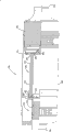
Turn to Figure 24 now, filtration 146 is shown as and is installed in the shell 186 (it can be a part that is entered the air inlet of engine or gas turbine by air purifier 179).In the arrangement illustrated, air flows in the shell 186 187 by filtration 146, and flows out shell 186 188.When dielectric structure when the filtration 146 of type is used for conduit or shell 186 as shown, need sealing system 144 to guarantee air stream, rather than get around it through dielectric structure 146.
The concrete sealing system of describing 144 comprises frame structure 190 and seal member 192.When using such sealing system 144, frame structure 190 provides supporting construction or backing, and seal member 192 is close to them, can be extruded and conduit or shell 186 form radial seals 194.
Still referring to Figure 24, shown in the specific embodiment in, frame structure 190 comprises a hard projection 196, it stretches out or extends from least one part of one of first and second flow surfaces 148,150 of filtration 146.Hard projection 196 in concrete device shown in Figure 24 extends axially from second flow surface 150 of filtration 146.
Shown projection 196 has a pair of by the terminal 104 relative faces 198,102 that engage.In preferable device, a support or a backing that seal member 192 will be provided in this first and second face 198,102, make sealing 194 can be formed on selected face 198 or 102 and the suitable surface of shell or conduit between and nestle up them.When using such structure, projection 196 will be a continuous member (Figure 22) that forms the cuff structure 106 of sealing.
When using such structure, shell or conduit can be external in projection 196 and comprise the cuff structure of seal member 192, are formed between the inner surface 110 of projection 196 and shell or conduit and nestle up their sealing 194.
In the specific embodiment shown in Figure 24, seal member 192 also engages with the end 104 of projection 196, makes seal member 192 cover to extend from outer surface 102, through terminal 104 and stretch to the projection 196 of inner surface 198.
Referring now to Figure 22 and 24,, framework 190 has band, edge or is used for framework 190 is fixed on dependence flange 107 on the dielectric structure 146.Rely on flange 107 to extend first distance down against intersection supporter 108 or at it.
When using the framework 190 of described type herein, the periphery of framework 190 has been applied an inside power.The supporter 108 that intersects is supporting framework 190.Term " support " is meant that intersection supporter 108 has prevented from radially to collapse under the power effect that the periphery to framework 190 applies at framework 190.
End portion 104 provides the support to compressible seal member 192.Compressible seal member 192 is constructed preferably and is installed and can be compressed fully, between the sidewall 110 of the end portion 104 of framework 190 and shell or conduit by compression.When fully compressing between part 104 and the sidewall 110 endways, radial seal 194 forms between media set 140 and sidewall 110.
A preferable configuration of seal member 192 is shown in Figure 25.The end portion 104 of framework 190 has formed wall or supporting construction, and between them, radial seal 194 can and nestle up them by compressible seal member 192 formation.The compression of compressible seal member 192 in sealing system 144 preferably wanted fully, so that be no more than 80 pounds, generally be to be no more than 50 pounds at embedment pressure, form radial seal under the condition of for example about 20-40 pound, this embedment pressure is enough little again, is enough to allow to replace easily with hand.
In better embodiment shown in Figure 25, seal member 192 is stepped cross-section structures, and its outermost size (for bowlder is a diameter) reduces gradually from first end, 112 to second ends 113, reaches required sealing.The preferable of concrete device profile shown in Figure 25 is described as follows: polyurethane foamed material has ladder that many (at least 3) increase gradually engaging with sidewall 110, and the sealing of impermeable fluid is provided.
Usually, sidewall 110 interference fits with shell 186 or conduit can be installed and be configured to media set 140.In the specific embodiment shown in Figure 24, compressible seal member 192 compresses between the end portion 104 of sidewall 110 and framework 190.After compression, because compressible seal member 192 has the trend that outwards expand into its nature, so compressible section 192 applies a power for sidewall 110, endways between part 104 and the sidewall 110 and nestle up their formation radial seals 94.
Various shells can be used for media set 140.In the specific embodiment that Figure 24 describes, shell 186 comprises main element or first outer shell 118 and the dismountable cover cap or second outer shell 120.In some devices, first outer shell 118 is fixed on an object, on truck.Second outer shell 120 is removably mounted on first outer shell 118 by locker.
In embodiment shown in Figure 24, with second end 150 of media set 140 together with adhering to frame 190 and compressible seal member 192 inserts in first outer shell 118.Media set 140 is force-fitted in first outer shell 118, makes the compression and nestle up them between the sidewall 110 of the end portion 104 of framework 190 and first outer shell 118 of compressible seal member 192 to form radial seal 194 between them.
In the process of using device shown in Figure 24, fluid enters in the canning 185 by the entrance area 124 of the direction shown in 187 at second outer shell 120.This fluid is by filtration device structure 146.Along with fluid passes through filtration device structure 146, pollutant is removed from this fluid.Fluid is pressed 118 direction, flows out from canning 185 at exit region 128.The compressible seal parts 192 of sealing system 144 form radial seal 194, prevent that the fluid of pollutant from flowing out canning 185, and not earlier by filtration 146.
Figure 26 is the perspective view of another embodiment of media set 130.Shown in the structure, media set 130 comprises filter medium 132 and sealing system 134.Filter medium 132 is designed to fluid such as air passes through filter medium 132 with contaminant removal.Sealing system 134 is designed to filter medium 132 is sealed in shell or conduit.
Except preferable dielectric material is formed following H section provides, the structure of the media set 130 of Figure 26-27 and shape description be in U.S. Patent No. 6,190, and in 432, its content is with reference to being incorporated into this.
In some preferable device, filter medium 132 is configured to have first flow surface 138 and second flow surface 140 on the other side in filtration 136.
In Figure 26, showing groove on some part 146, comprise openend and blind end.Should be understood that this part 146 is representatives of whole flow surface 140 (and first flow surface 138).For the purpose of simply clear, in other remainder 149 of flow surface 140, do not show these grooves.Being used for the plane of the top of media set 130 of described system and device and bottom and side view herein is presented at and is filed in awaiting the reply and the U.S. Patent application series No.29/101 of common transfer of on February 26th, 1999, in 193, title is " filter element with sealing system ", and its content is with reference to being incorporated into this.
As the embodiment of Figure 22, media set 130 comprises sealing system 134.In preferable structure, sealing system 134 comprises framework 148 and seal member 150.
The shape of framework 148 is non-circular, and for example non-circle specifically is a runway shape, installs and be configured to be contained in an end of filter medium 132.Concrete is that framework 148 has band, edge or is the dependence flange 151 of runway shape usually.Rely on flange 151 to extend a segment distance down, be used for framework 148 is fixed on the media set 130 against intersection supporter 152 or at it.
In the use of shown device, around framework 148, applying inside power.The internal force that applies at semicircle two ends 141,142 can cause straight section 143,144 to be arc or crooked.The effect of intersection supporter 152 provides the rigidity of structure and straight section 143,144 is supported.As can be seen from Figure 26, shown intersection supporter 152 forms a construction system 154 between relative straight section 143,144.Construction system 154 comprises the pillar 156 of many rigidity, and their remainders best and framework 148 are made an integral body.
The structure of framework 148 is similar to framework 90.Like this, framework 148 comprises terminal 158 (Figure 27).In preferable device, terminal 158 as the ring packing supporter.In preferable system, compressible seal member 150 has and Fig. 5 compressible seal parts 92 similar structures.
Preferably, media set 130 is installed in the shell of conduit or air purifier.In Figure 27, described shell is made of cover cap 160 and main element 162.Cover cap 160 constitutes airflow inlet 164.Main element 162 constitutes air stream outlet 166.Shell also has a preliminary clearning device 167 that is positioned at media set 130 fronts, as U.S. Patent No. 2,887, and 177 and 4,162,906 is described, and its content is with reference to being incorporated into this.In the example shown in, preliminary clearning device 167 is contained in the cover cap 160.The dust discharge pipe 168 that has the dust that will be collected in the prepurifier 167 and chip to discharge on the cover cap 160.
The preferable material composition of medium 132 is described in the following H joint.
Figure 28 shows another filter for installation 174.Form following H joint is described except its preferable dielectric material, this filter for installation 174 is described in U.S. Patent No. 5,820, and in 646, its content is with reference to being incorporated into this.
Media set 176 comprises the groove filter medium 184 of structure as described in Figure 23.
E.
Canonical system; The gas handling system of gas turbine
The gas handling system 200 that in Figure 29, shows gas turbine engine systems.Air stream is pressed arrow 201 directions and is sucked in the gas handling system 200.Gas handling system 200 comprises many air filters 202 that are fixed on usually on the tube sheet 203.In preferable system, tube sheet 203 is configured to supporting filter 202 with the angle with respect to vertical axis.Preferable angle is between 5-25 °, for example about 7 °.When system's 200 inoperation, so just can allow liquid from filter 202, discharge.
Air purifies in air filter 202, flows into forward in the gas turbine powered generator 205 along arrow 204 then, is used for generating.
An example 210 that in Figure 33, shows the air inlet of small size gas turbine.Usually, small size gas turbine is the midget plant of gas turbine, generally is used for stand-by generator.In some cases, these small size gas turbines are about 24 inches * 18 inches, and electromotive power output is generally 30-100 kilowatt.The air mass flow of these systems is generally 1000-10,000cfm.
In Figure 33, air stream sucks in the gas handling system 211 along arrow 212.Gas handling system 211 comprises filter 213.Along with air is inhaled into by filter 213, air purifies therein, flows into forward in the gas turbine 215 along arrow 214 then.Then, gas turbine just provides power for generator, fluid compression engine or fluid pump.As described below, filter is configured to the form of the compound of block media and at least one individual layer, and in the form that is multilayer " fine fibre " in some cases, than the existing filter without these dielectric composites structure can improve the performance (particularly operating efficiency) of filter.
F.
The example that is used for the filter of gas turbine engine systems
An example that is used for the air filter 202 of system 200 or system 210 is shown in Figure 30-32.The preferable dielectric material that provides except H joint was formed, air filter 202 was described in the U.S. S.N.09/437 of the common transfer that is filed on November 10th, 1999, and in 867, its content is with reference to being incorporated into this.Usually, air filter 202 comprises first or main filter element 220 (Figure 30 and 32) and as second filter element 222 (Figure 31 and 32) of prefilter.Term " prefilter " is meant the separator that is arranged on main main filter element 220 fronts, and it is used for removing bulky grain from air-flow.Main filter element 220 and pre-filtering parts 222 preferably are fixed in the collar tube sub-assembly 224 that can remove and install in the hole 226 of tube sheet 203.Usually, air flows in the system 200, the pre-filtering parts 222 of at first flowing through, the main filter element 220 of flowing through then.After leaving main filter element 220, air imports in the generator 205.
Usually, parts 220 are made of channel medium or z shape medium 230, as shown in Fig. 2 and 3.Should be understood that and schematically represent exit face 228 in Figure 30, promptly is a part that only shows the face 228 with groove.Should be understood that in general system whole 228 all has groove.
Medium 230 can be the polyester synthetic medium, and this medium is made by the mixture of cellulose or this class material, and handles with fine fibre.
Preferably, pre-filtering parts 222 are the wrinkle structures 236 that comprise many single wrinkles 237.These wrinkle 237 tortuous installations.It is circular cross section substantially that preferable pre-filtering parts 222 have.
In some better embodiment, at least 15 wrinkles 237 are arranged in the pre-filtering parts, be no more than 80 wrinkles 237, generally be 30-50 wrinkle 237.Wrinkle structure 236 is made by the medium 240 that is folded into around the form of the wrinkle 237 of axis 241.The medium 240 of useful type comprises fibrous glass, perhaps air lay method medium.The specific performance of useful medium 240 comprises: the dry-laying technology filter medium that is made of the polyester fiber of random orienting forms the fabric of heavy 2.7-3.3 oz/yd 3 (92-112g/m3), free the thickness thickness of 0.002psi compression (promptly) 0.25-0.40 inch (6.4-10.2mm), permeability at least 400 feet per minute clocks (122m/ minute).
Usually, pre-filtering parts 222 detachably are installed in the collar tube sub-assembly 224 replaceablely.Collar tube sub-assembly 224 will describe in detail hereinafter.In some system, the inwall extruding by pasting collar tube sub-assembly 224 or the end of compressed media 240 are fixed on pre-filtering parts 222 in the collar tube sub-assembly 224.
Fixing and be trapped among on the main filter element 220 according to the collar tube sub-assembly 224 of the preferable filter 202 of the principles of construction of this paper.Usually, collar tube sub-assembly 224 is used for supporting master unit 220 on the throne in system 200.Preferable collar tube sub-assembly 224 will support the pre-filtering parts 222 that place master unit 220 fronts.
As can be seen, collar tube sub-assembly 224 preferably has the cross section with main filter element coupling from Figure 30 and 31.Collar tube sub-assembly 224 comprises the encirclement wall 244 that is bent to form ring 245 forms.Collar tube sub-assembly 224 preferably can encase at least 30% of main filter element 220 axial lengths with respect to main filter element 220 orientations.In many common devices, collar tube sub-assembly 224 encases more than 50% of main filter element 220 axial lengths.In fact, in most of preferred means, collar tube sub-assembly 224 encases at least all length (promptly 100%) of main filter element 220.In many typical application, the radius of collar tube sub-assembly 224 is at least 10 inches, generally is the 15-30 inch, in some cases, is no more than 50 inches.
Cover plate or geometrical clamp 252 (Figure 30) are stretched on abutment 254 collar tube sub-assembly 224 are fixed as final configuration.Preferably, geometrical clamp 252 is fixed on the collar tube sub-assembly 224 in a permanent way; For example, by ultrasonic bonding.
Turn to Figure 32 now.Can see that flange 246 is at axial sides 256 upper support seal members 248.Seal member 248 generally includes rounded washers 258.Packing ring 258 preferably is fixed on the flange 246 by the adhesive between this side 256 of packing ring 258 and flange 246.Packing ring 258 is positioned on the flange 246, makes it encase wall 244 and master unit 220 fully.
Described device also comprises and is used for collar tube sub-assembly 224 is clamped in system on the tube sheet 203.In said embodiment, pincer system comprises many lock pins or anchor clamps 260.When collar tube sub-assembly 224 operationally is installed on the tube sheet 203, enough lock pins or anchor clamps 260 should be arranged, well and closely seal 250 so that between flange 246 and tube sheet 203, form; What for example, illustrate is 4 anchor clamps 260.In Figure 32, show the cross section of anchor clamps 260.Each anchor clamps 260 comprise lever 261, protuberance 262 and plate 263.The hole that is used for holding securing member such as bolt 264 is arranged on the plate 263, anchor clamps 260 are fixed on the tube sheet 203.The effect of protuberance 262 is that pressure is applied on the flange 246, and heads on tube sheet 203 compression seal parts 248.The effect of lever 261 is optionally tube sheet 203 is shifted to and moved apart to protuberance 262.In other embodiments, anchor clamps 260 can be with tight on hand, as using wing nut.
In general operation, the total pressure drop on filter 202 two sides is about the 0.6-1.6 inches of water(in H.This pressure that comprises main filter element 220 and prefilter 222 falls.Usually, independent prefilter 222 pressure fall and are about the 0.2-0.6 inches of water(in H, and independent master unit 220 pressure fall and are about the 0.4-1 inches of water(in H.
Figure 34-36 shows another example of air filter that is used for system 304 or system 302.The preferable dielectric material that provides except following H joint was formed, air filter was described in the U.S. Patent application S.N.09/593 of the common transfer that is filed on June 13rd, 2000, and in 257, its content is with reference to being incorporated into this.
Figure 35 show be decomposition, the filter 213 of assembly form not, and Figure 14 shows the filter 213 that assembles up use.Usually, air filter 213 comprises water-separator 270, filter 272 and shell 274.When assembling for use, shell 274 generally is fixed in the tube sheet 276.Preferably, by shell 274 being welded on the tube sheet 276 or, shell 274 being fixed on the tube sheet 276 by shell 274 being fixed on the tube sheet 276 with bolt.
Moisture in the inlet air flow can destroy the integrality of filter 272, and gets rusty and the internal mechanism of destruction system 302 owing to causing.In order to address this problem, filter comprises a water-separator 270.Usually, water-separator 270 is before inlet air flow arrives filter 272, from wherein separating and collecting moisture.In one embodiment, water-separator 270 comprises many flat screens, for example metallic screen fabric.
Usually, filter 272 is before the inlet air flow 212 of Figure 33 enters the internal mechanism of system 302, from wherein removing pollutant.Preferably, filter 272 is configured to allow straight-through air-flow directly to enter in the inlet face 284 by filter 272, and leaves from opposed exit face 285, and its, fluid flow to into the wander about as a refugee direction of leaving actinal surface 285 of the direction of inlet face 284 and fluid identical this moment.
Shown filter 272 comprises an extraction mechanism 290.Extraction mechanism 290 is configured to allow the user remove filter 272 from shell 274 easily.In an illustrated embodiment, extraction mechanism 290 comprises handle 292 and keeps mechanism 294 (Figure 34).Usually, handle 292 is knobs 296.In an embodiment shown in Figure 34, keep mechanism 294 and comprise bolt 298 that is contained on the knob 296 and the nut 299 that is positioned at the bolt other end.Perhaps, the core of haulage gear and filter medium can be an integral body.
Usually, shell 274 is configured to accept and holds filter 272 and make things convenient for it and the sealing of filter 272.In an embodiment shown in Figure 36, filter housing 274 has the angle with outer wall 304 be at least 10 °, better be 10-210 °, about 15 ° transitional region 302 preferably.Transitional region 302 also helps to seal filter 272, as hereinafter describing in detail.
In use, seal washer 312 is sealing the junction 314 between filter 272 and the shell 274.In installation process, filter 272 is inserted in the shells 274, head on block 310 up to its end 315.Along with the installation of filter 272, be compressed in the transitional region 302 of seal washer 312 between filter 272 and shell 274, seal up junction 314.
In assembling process, shell 274 is slipped in the tube sheet 276, fixing up to the mounting flange 306 of shell 274 against tube sheet 276.Then, filter 272 is placed shell 274.Specifically be that filter 272 is slipped in the shell 274, head on block 310 up to an end 315 of filter 272.The compression of seal washer 312 parts, filter 272 is contained in the shell 274 closely as a result.
In operation, use filter 213 by the following method: will in system 302, import in the gas handling system 211 along arrow 212 by filtered air.The air filter 272 of flowing through.Air enters at inlet face 284, and the groove structure 288 of flowing through flows out from exit face 285.Air is inhaled in gas turbine or the generator 215 therefrom.
G.
Canonical system; The fuel cell air inlet
The fuel cell air inlet is shown in 330 of Figure 37.As shown in figure 37, atmosphere or surrounding air 331 enter in the filter 332 by import 333.Before entering filter 332, atmosphere 331 is the dirty air with various physics (for example particle) and chemical pollutant.Filter 332 is configured to remove all contaminations from dirty air, provide from filter 332 flow out purify air 334.Purifying air 334 is the suction gas of fuel cell 335, is used for generating.
See Figure 37 again, along with dirty air by the import 333 in the shell 336, atmosphere 331 enters in the filter 332, and enters the dirty air side 337 of filter element 338.Along with air enters in the clean air side 339 by filter element 338, pollutant is filtered parts 338 and removes so that filtered air 334 to be provided.Filtered air 334 uses through the outlet 340 outflow filter devices 332 of shell 336 and by device 341.
Usually, " low-temperature fuel cell " approximately 70-100 ℃, operate under sometimes up to 200 ℃ temperature.High-temperature fuel cell is generally insensitive to chemical pollutant, because their operating temperature is higher., high-temperature fuel cell is very sensitive to the chemical pollutant of particulate pollutant and some form, and high-temperature fuel cell just can be benefited from following herein filtering characteristic like this.One class low-temperature fuel cell generally is called as " PEM ", gets because of it uses PEM.The example of other each types of fuel cells that can be used in combination with filter of the present invention comprises: for example U.S. Patent No. 6,110, and 611,6,117,579,6,103,415 and 6,083,637, its disclosed content is with reference to being incorporated into this.Various fuel cells can available from, for example the General Motors company of the Energy Partner company of the Siemans AG company of the International fuel cell company of the Ballard Power Systems Co., Ltd of Vancouver, CAN, the Connecticut State, the Proton Energy Systems Co., Ltd of Connecticut State Rocky Hill, the U.S. fuel cell company of Massachusetts, German Erlangen, Florida State L.C., Michigan State Detroit and Japan motor group of Toyota.
As described below, before air is used for fuel battery operation, filter from atmosphere with contaminant removal.As described below, structure is block media and at least one individual layer, and in some cases, the filter of the form of the compound of multilayer " fine fibre " can strengthen the performance of filter (particularly operating characteristics).Fine fibre is handled the filter efficiency that helps improving under most of filter shape and environmental condition.Surpass in 120 the rugged environment at some filtration temperature, comprise low temperature and high-temperature fuel cell, fine fibre can use and provide the filter life of prolongation usually.
H.
The example that is used for the filter of fuel cell gas handling system
Figure 38 shows the filter 350 of the system that is used for Figure 37.Filter 350 comprises the shell 352 that forms import 354 and outlet 356.Dirty air enters in the filter 350 by import 354, purifies air to leave by exporting 356.
In shell 352, be provided with filter element 358 and noise suppression component 360.Suppress parts 360 and comprise first resonator 361 and second resonator 362.First resonator 361 is configured to weaken the peak of about 900Hz, and second resonator 362 is configured to weaken the peak of 550Hz.
The filter element 358 of Figure 38 usually and filter element structure 40 (Figure 22) constitute similarly.Like this, it comprises the media set 364 (as shown in figure 38) of the channel medium 366 that is rolled into filter element 358.
When the shell 352 that filters parts 358 and online mobile usefulness uses jointly, air will enter in the shell 352 by import 354 along a direction, enter in the filter element 358 through first flow surface 368 along same direction, from second flow surface, 370 outflow filter parts 358, and also flow out shells 352 through exporting 356 along same direction along same direction.
As the embodiment of Figure 22 and 24, radial seal 372 by between the inner sealing surface 378 of framework 376 and shell and the compression that nestles up their seal washer 374 form.
Chemistry removal part generally comprises physical absorbent or chemisorbed agent material, for example the material of drier (i.e. the material of absorption or absorption water or steam) or absorption or absorption VOC and/or sour gas and/or alkaline gas.Term " sorbent material ", " sorbing material ", " sorptive material ", " absorber material ", " absorbing material ", " absorbent material " and similar any word comprise any material of removing chemical pollutant by absorption or absorption.Suitable sorbing material comprises, for example activated carbon, activated carbon fiber, impregnated carbon, activated alumina, molecular sieve, ion exchange resin, ion-exchange fibre, silica gel, aluminium oxide and silica.Any one of these materials can mix, be coated with or flood with following material: potassium permanganate, calcium carbonate, potash, sodium carbonate, calcium sulfate, citric acid or their mixture.In some embodiments, sorbing material can mix with second material or flood.
Sorbing material generally comprises the material of particle or granulation and can exist for particle, bead, fiber, fine powder, nanostructured, nanotube, aerogel form; perhaps can be used as at base material, exist as the coating on ceramic beads, overall structure, paper medium or the metal surface.Usually, the material of sorbent material, particularly particle or granulation provides with material bed form.
On the other hand, sorbing material can be made into whole form, as sheet, spherolite, bead or wrinkle or honeycomb, they or can further be shaped.At least in some cases, in the normal or expected endurance of filter, the sorbent material of shaping keeps its shape fully.The sorbing material that is shaped can be formed by the free flowing granule material that combines solid or liquid adhesive, makes the non-goods that flow freely then.The sorbent material that is shaped can pass through, and for example mold, pressing mold or pressing method form.The sorbing material that is shaped is described in, and for example U.S. Patent No. 5,189, among 092 (Koslow) and 5,331,037 (Koslow), their references is incorporated into this.
The adhesive that is used to provide molded article can be dry, promptly is the form of powder and/or particle, and perhaps this adhesive can be adhesive liquid, solvation or that disperse.Some adhesive as curable urethane of humidity and the material that is commonly referred to as " hot melt ", can be applied directly on the sorbent material by gunite.In some embodiments, use interim liquid adhesive, it comprises solvent or the dispersant that can remove in the mold process.Suitable adhesive comprises, for example latex, microcrystalline cellulose, polyvinyl alcohol, ethane-acetic acid ethyenyl ester, starch, carboxymethyl cellulose, polyvinylpyrrolidone, Tri-Compress and sodium metasilicate.Preferably, the composition of moulding material comprises at least about 70 weight %, and generally is no more than the sorbent material of about 98 weight %.In some cases, the adsorbent of shaping comprises 85-95 weight %, the sorbing material of preferably about 90 weight %.The adsorbent that is shaped generally comprises and is no less than about 2 weight, is no more than the adhesive of about 30 weight %.
Being used for the filter chemistry and removing another embodiment of the suitable sorbing material of part, is the sorbing material that comprises a kind of carrier.For example, sieve fabric or bare cloth can be used to support sorbing material and adhesive.Polyester and other suitable material can be used as sieve fabric or bare cloth.Usually, any carrier is no more than the about 50% of sorbing material weight, and often is about 20-40% of total adsorbent weight.The amount of the adhesive in the absorbent articles of the shaping with carrier generally is about the 10-50% of total adsorbent weight, and the amount of sorbing material generally is about the 20-60% of total adsorbent weight.
Chemistry is removed part can comprise the strong alkaline substance that is used for removing acid contaminant from air, or is used for removing from air the highly acid material of alkaline pollutant, and perhaps both have concurrently.Preferably, alkaline matter and acidic materials are spaced from each other, and make their unlikely cancelling out each other.In some embodiments, sorbing material itself can be highly acid or strong alkaline substance.These examples of material comprise polymer beads, activated carbon media, zeolite, clay, silica gel and metal oxide.In other embodiments, can provide face coat on highly acid and strong alkaline substance particulate, bead, fiber, fine powder, nanotube and the aeroge as carrier such as granulation.Additionally or additionally, acidity and the alkaline matter that forms acid and basic surface can spread at least a portion carrier; This can for example finish by being coated with or flooding this carrier with acidity or alkaline matter.
Alkalescence and acidic materials can be present in the chemistry of filter element and remove in the part; But preferably this two classes material is spaced from each other, and makes them can interreaction and neutralization.In some embodiments, basic matterial, acid material or both can separate with sorbing material such as activated carbon.
The example that often is present in the atmospheric air and is considered to the acid compound of fuel cell pollutant comprises: sulfur oxide, nitrogen oxide, hydrogen sulfide, hydrogen chloride and VFA and non-volatile organic acid.The example that often is present in the atmospheric air and is considered to the alkali compounds of fuel cell pollutant comprises: ammonia, amine, acid amides, NaOH, lithium hydroxide, potassium hydroxide, volatility organic base and non-volatile organic base.
For the PEM fuel cell, cathode reaction takes place under acid condition, exists with regard to bad alkaline pollutant like this.The example that is used to remove the preferred materials of alkaline pollutant such as ammonia is the active carbon particle bed with the citric acid dipping.
Second example of filter that can be used for the system of Figure 37 is shown among Figure 39 with partial cross section as filter 380.Filter 380 comprises the shell 382 that forms import 384 and outlet 386.Dirty air enters in the filter 380 by import 384, purifies air to leave by exporting 386.Noise suppression component 388 is resonators 390.Filter element 391 is installed in the shell 382, and is similar with filter element 358.
I.
The preferable dielectric structure that above-mentioned filter element is used
The fine fibre structure of filter comprises the structure of a two-layer or multilayer, this filter contain one or more synthetic with one or more layers, fabrics cellulosic or that mix combine or the fine fiber layer that separated by them.Another preferably characteristics are the structures that comprise the mixture of fine fibre in the matrix or other fiber.
We think that the key property of fiber in the filtration device structure and micrometer fibers layer is relevant with heatproof degree, protection against the tide or moisture resistance and solvent resistance, particularly when micrometer fibers contacts with moisture, moisture or solvent at elevated temperatures.In addition, second of material of the present invention critical nature is relevant with the adherence of material and underlying structure.The adhesion of micrometer fibers layer is a critical nature of fibrous material, can make this material and does not separate the micrometer fibers layer from substrate, and micrometer fibers layer and substrate can be processed into the structure that comprises coiled material wrinkly and other structure and not had significant layering.We find in the heating steps of this manufacture method, temperature be elevated near but just be lower than a kind of melt temperature of polymeric material, generally be to be lower than minimum melt temperature, can significantly improve fiber each other and to the adhesion of substrate.In melt temperature or when being higher than melt temperature, fine fibre can be lost its fibre structure.The control rate of heat addition is also very crucial.Be exposed to for a long time under its crystallization temperature as fruit fiber, it also may lose fibre structure.The polymer performance that careful heat treatment also can make outside additive layer cause improves, and goes up and the lip-deep hydrophobic or oleophobic group of exposed fiber because additive material can be moved to the surface.
The criterion of performance is that this material can be in various operating temperatures, for example intactly keeps 1 hour or 3 hours according to final use under 140 °F, 160 °F, 270 °F, 300 °F, keeps 30%, 50%, 80% or 90% filter efficiency simultaneously.The criterion of another performance is that this material can be in various operating temperatures, for example intactly kept 1 hour or 3 hours according to final use under 140 °F, 160 °F, 270 °F, 300 °F, in filter course, keep effective fine fibre of 30%, 50%, 80% or 90% simultaneously.In these temperature and can retention property under low humidity, high humidity and water saturation air very important.It is moistureproof that micrometer fibers of the present invention and fibrous material are considered to, and this material can stand to be higher than in temperature 160 immersion, and can keep efficient above about 5 minutes.Similarly, the solvent resistance of micrometer fibers material of the present invention and filtering material get self energy 70 °F with solvent such as ethanol, hydrocarbon,, hydraulic fluid or aromatic solvent contact and have the material that surpasses about 5 minutes time and keep 50% efficient.
Fine fibre material of the present invention can be used in the various filters, comprises the air inlet or the suction system that are used for dedusting pulse purification and non-pulse filter purifying, gas turbine and engine; Heavy-duty engine air inlet or suction system, light vehicle engine charge or suction system; The compartment air; Offroad vehicle compartment air, disc driver air, copying machines toner are removed; The HVAC filter that is used for commerce or dwelling house filtration applications.The paper filter element is the form of widely used area load type medium.Usually, the paper parts are mats of the cellulosic vertical orientated with the air-flow that is loaded with particulate matter, synthetic or other fiber.But paper is configured to the air-flow infiltrate usually, and has enough thin aperture and suitable porosity, passes through to stop the particle greater than selected size.Along with gas (liquid) by filter paper, filter paper in face of the face of air-flow spread and tackle with catch and retained gas (liquid) flow in the particle of selected size.Particle is collected as the dirt piece on this face of filter paper.Behind the certain hour, this dirt piece also plays the filter effect, can increase filter efficiency.This is sometimes referred to as " timeliness ", and promptly efficient improves greater than initial efficient.
Above-mentioned simple and easy filter is easy to generate at least two class problems.At first be comparatively simple fault of construction on the paper, for example the crack can cause thrashing.Next is that particulate matter can be piled up on the face of filter plane to air-flow rapidly, forms thin dirt piece or knoisphere, increases pressure and falls.Used the whole bag of tricks to increase the filtration system of area load, as the life-span of filter paper.A kind of method provides the medium in the wrinkle structure, and the medium of the non-wrinkle structure in surface area ratio plane of the feasible medium that contacts with air-flow is big.Increased the life-span of filter although it is so, but still be very restricted.For this reason, the medium of area load is mainly used in by the speed of filter medium lower, is no more than about 20-30 feet per minute clock usually, general about 10 feet per minute clocks or lower situation.Term in the literary composition " speed " is the average speed (being volume flow/media area) by medium.
In general, along with the air velocity by goffered filter increases, the life-span of filter square successively decreases by speed.Like this, when the area load filtration system of goffered filter as being used for needs greatly during the particulate filter of the system of the gas of flow, need filter medium that bigger surface area is arranged.For example, the diameter of the cylindrical goffered filter element of the diesel truck of general road running is about the 9-15 inch, is about the 12-24 inch, the about 1-2 inch of wrinkle depth.Like this, the filter table area of medium (on the face) is generally the 30-300 square inch.
In many purposes, particularly those relate in the purposes of high flow, use the filter medium of the replaceable type that is commonly referred to " degree of depth " medium sometimes.It in the general depth media fibrous material of thicker entanglement.Depth media characterizes with the percentage of its porosity, density or solid content usually.For example, the medium that solid content is 2-3% is the depth media pad of fiber, and about 2-3% of its cumulative volume is fibrous material (solid), and all the other are the air or the gas compartment.
Another the useful parameter that characterizes depth media is a fibre diameter.Admittedly remain unchanged if contain percentage, but fibre diameter (size) reduces, and then hole or interfibrous interval reduce; It is more effective to be that fiber becomes, and will more effectively catch smaller particles.
A common conventional depth medium filter is a medium dark, that density is constant relatively (or even), and promptly the solid content of depth media remains substantially invariable system." substantially constant " herein is meant that density only has less inhomogeneities, even if having, also can only find in the depth bounds of medium.This inhomogeneities for example can slight compression causes to outside composition surface by the container of fixing filter medium.
Developed the device of gradient density depth media.Some such unit describes are in U.S. Patent No. 4,082, in 476,5,238,474 and 5,364,456.Usually, dark medium apparatus can be designed to provide " load " of the granular materials that runs through its volume or the degree of depth basically.Like this, system compares with area load, and when reaching whole filter life, these devices just can be designed to the more substantial granular materials of load., be efficient because usually these devices sacrifice, so need be than the medium of low-solid content.Big efficient and long life-span have been designed to provide as those gradient density system in the above-mentioned patent.In some cases, utilize the area load medium as " modification " filter in these devices.
Filter media construction of the present invention comprises the permeable crude fibre medium of ground floor or has the substrate of first surface.The ground floor fine fiber media is fixed on the first surface of the permeable crude fibre medium of ground floor.Preferably, be at least 10 microns of average diameters in the permeable crude fibre material of ground floor, the fiber of general and preferably about 12 (or 14)-30 micron.Simultaneously, preferably, the basic weight of the permeable crude fibre material of ground floor is no more than about 200g/m
2, better be about 0.50-150g/m
2, 8g/m at least preferably
2Medium.Preferably, the thickness of the permeable crude fibre medium of ground floor is at least 0.005 inch (12 microns), generally is 0.0006-0.02 inch (15-500 micron), about 0.001-0.030 inch (25-800 micron) preferably.
In preferable device, the permeable crude fibre material of ground floor is a kind of material, if this material that uses Frazier permeability method of testing pair and surplus of the fern of structure to separate is tested, this material will show 1m/ minute at least, general preferably about 2-900m/ minute permeability.When mentioning efficient, except as otherwise noted, be meant the efficient of under 20fpm (6.1m/ minute) speed, measuring with the air-flow that contains 0.78 μ monodisperse polystyrene spherolite according to ASTM-1215-89 as described herein herein.
Preferably, the fine fibre material layer that is fixed on the first surface of permeable crude fibre dielectric layer is one deck nanometer and micrometer fibers medium, wherein, the average diameter of fiber is no more than about 2 microns, better is to be no more than about 1 micron usually, and general preferably fibre diameter is less than 0.5 micron and in the scope of about 0.05-0.5 micron.Simultaneously, preferably, the gross thickness that is fixed on the ground floor fine fibre material on the first surface of ground floor porous fiber material is no more than about 30 microns, be more preferably and be no more than 20 microns, preferably be no more than about 10 microns, and about 1-8 of general preferably this layer fine fibre average diameter doubly (be more preferably and be no more than 5 times).
Some preferred means of the present invention comprises usually at the filter medium described in total filtration device structure.Some preferred means of using comprise with folding folding shape structure cylindrical, that have general longitudinal extension, i.e. edge and the folding medium of the same direction of the cylindrical longitudinal axis.For these devices, medium can embed in two end caps of conventional filtration device.Optionally, these devices can comprise upstream lining and the downstream lining that is used for common conventional purpose.
In some purposes, medium of the present invention can be used to the medium with other type, and for example conventional media engages, in order to improve total strainability or life-span.For example, medium of the present invention can be laminated on the conventional media, uses with stacked arrangement; Perhaps can insert in the dielectric structure in one or more zones that (global feature) comprise conventional media.Medium of the present invention can be used on the front of conventional media, in order that load preferably; And/or the back that is used in conventional media is as modified filter efficiently.
Some device of the present invention also can be used in the fluid filter system, promptly is that the granular materials that wherein will filter out carries with liquid.Simultaneously, some device of the present invention can be used in the smoke collector, for example is used for filtering from air in the device of thin smog.
The invention provides the method for filtration.These methods generally include uses above-mentioned medium to filter preferably.From following description and embodiment as can be seen, medium of the present invention can design and construct especially, so that the long life-span advantageously is provided in the system of more promising effect.
The various filters that disclose in each patent have been advocated the various aspects of the filtration device structure that together uses with filtering material.People's such as Engel U.S. Patent No. 4,720,292 disclose the radial seal design of the filter that is used to have general cylinder shape filtering element design, columniform by having, the radially inner lining face of this filter element softer and the end cap seal of rubber like.People's such as Kahlbaugh U.S. Patent No. 5,082,476 discloses the filter design of using depth media, and this depth media assembly contains the foamed material substrate with the folding shape element that combines with micrometer fibers material of the present invention.People's such as Stifeman U.S. Patent No. 5,104,537 relates to the filtration device structure of the medium that is used for filter liquide.Liquid entrainment enters in the filter housing, and the outside by filter enters in the inner loop core, returns active use the in the structure then.These filters are very useful to the filtered fluid hydraulic fluid.People's such as Engel U.S. Patent No. 5,613,992 has shown typical diesel engine intake filtration.This structure obtains air from the outside of the shell that may carry or not carry secretly moisture secretly.Moisture can lead to outer casing bottom and drain from shell air by filter.People's such as Gillingham U.S. Patent No. 5,820,646 disclose the Z filtration device structure, and its uses the special marked fold shape filter design comprise inaccessible passage, need fluid to pass through in " Z " shape passage the strainability of one deck filter medium to obtain suiting at least.The filter medium that forms the Z-shaped pattern of rugosity can contain fine fiber media of the present invention.People's such as Glen U.S. Patent No. 5,853,442 discloses the bag room structure with the filter element that can contain fine fiber structure of the present invention.People's such as Berkhoel U.S. Patent No. 5,954,849 has shown a kind of dust catcher, and it is used for handling generally is the air that is loaded with a large amount of dusts, from wherein filtering out dust, contains a large amount of dusts in this air owing to workpiece processing produces.At last, the U.S. Patent No. 425,189 of Gillingham discloses the disk filter that uses the Z filtration device structure.
More than the useful filtration of polymeric material of the present invention, the fine fibre material that the present invention includes micrometer fibers and nanofiber and fine fibre material of the present invention is made the general remark of each side, the understanding of the present invention being operated the general technology principle is provided.The concrete exemplary materials of the following stated is the examples of materials that can be used for making fine fibre material of the present invention, and following material has disclosed best pattern.Made these exemplary materials, use be following characteristic and operating condition.Use the electrostatic field of improving oneself to play the electrostatic force of pulling effect, the polymeric spray thing is pulled into very thin filament, obtain diameter less than 10 microns the static fiber that reels off raw silk from cocoons.Though in the static drawing process, can use polymer melt,, the most handy polymer solution makes the fiber that is narrower than 1 rice.When polymer constituted more minor diameter, solvent evaporated and helps reducing the size of fiber.Based on a variety of causes, choice of Solvent is very crucial.If solvent is done too soon, so fiber can flatten and diameter big.If solvent is done too slowly, solvent can lysigenous once more fiber.Therefore rate of drying and fibroplastic cooperation are very crucial.When high production rate, a large amount of discharge air can prevent imflammable gas and reduce the danger of catching fire.Non-flammable solvent is useful.In production environment, process equipment needs purification frequently.The situation that the safety and low toxicity solvent can make the workman be exposed to hazardous chemical is reduced to minimum.Static reels off raw silk from cocoons and can operate under the flow velocity of 1.5 miles of every transmitter per minutes, 8 inches range, 88 kilovolts transmitter voltage, 200 rev/mins transmitter rotating speed and these conditions of relative humidity of 45%.
The selection of polymer system is very important concerning given purposes.For adopting pulse to purify, micrometer fibers layer as thin as a wafer helps the outer surface that can provide particle capture and release under the very little situation of the pressure loss making.The preferred diameter that uses should be less than 0.3 micron fibre thin layer less than 2 microns.Good tack is very important between micrometer fibers or nanofiber and its deposition substrate.When the compound that is made of substrate and micrometer fibers and nanofiber when filter made, this compound can be applicable to the good filter medium of auto purification.Purify described surface by repetition pulse dorsad and just upgraded filter medium.When applying big active force from the teeth outwards, the fine fibre of poor adhesion delamination occurs owing to pulse dorsad in the substrate, described pulse dorsad from filter interior by the substrate micrometer fibers of flowing through.Therefore, good adhere to and the purposes of adhering to success that basilar fibers and static reel off raw silk from cocoons between the fiber is very important between the micrometer fibers.
The fiber that uses various polymeric materials to make can obtain to adapt to the product of above-mentioned requirements.Fine fibre with good adherence performance can and contain various nylon such as the polymer of nylon 6, nylon 4,6, nylon 6,6, nylon 6,10 and copolymer and their copolymer make by for example polyvinylidene chloride, polyvinyl alcohol.Can make fiber with excellent by PVDF, but making the enough little fiber of diameter needs chlorinated solvent.Nylon 6, nylon 66 and nylon 6,10 can carry out static and reel off raw silk from cocoons.But it is for example formic acid, m-cresols, trifluoroethanol, hexafluoroisopropanol equal solvent or very difficult operation, or very expensive.Because of its hypotoxicity, preferred solvent comprises water, ethanol, isopropyl alcohol, acetone and N-methyl pyrrolidone.Made extensive studies with this solvent system compatible polymers.We have found that the fiber that is made by PVC, PVDC, polystyrene, polyacrylonitrile, PMMA, PVDF need obtain structural behaviour by extra adhesive bonding method.When we also found, ethanol water-soluble when polymer, isopropyl alcohol, acetone, methyl alcohol and their mixture and successfully make fiber, they had good adhesion property to substrate, can make the good filter that is suitable for auto purification thus.When filter is used for very high dust concentration, by air back of the body pulse auto purification or stranded be useful.The fiber that is made by polyamide that dissolves in alcohol and polyvinyl alcohol successfully uses in this purposes.The polyamide example that dissolves in alcohol comprises the Macromelt6238,6239 and 6900 that buys from Henkle; The Elyamide 8061 that buys from duPont and 8063 and the SVP 637 and 651 that buys from Shakespear monofilament Company.Other one group of polyamide that dissolves in alcohol is 8 type nylon, alkoxyalkyl modification of nylon 66 (with reference to Nylon Plastic handbook, the 447th page, melvin Kohan etc., hanser Publisher, New York, 1995).The polyvinyl alcohol example comprises from Kuraray, the PVA-217 that Japan buys, 224 and the Vinol540 that buys from Air Products and Chemical Company.
Experiment
Use following static drawing process condition to produce following material.
Use revolving expeller system or capillary needle system to reel off raw silk from cocoons and make following material.These two kinds of systems all can produce essentially identical fibrous material.
Described flow velocity is 1.5 miles of every transmitter per minutes, and range is 8 inches, and transmitter voltage is 88 kilovolts, and relative humidity is 45%, and the rotating speed of revolving expeller is 35 rev/mins.
Embodiment 1: the influence of fiber size
With end group titration (J.E.Walz and G.B.Taylor work " determining of nylon molecular weight ", chemistry annual report Vol.19, Number 7, the 448-450 pages or leaves (1947)) analyze the molecular weight of b by the fine fibre sample of nylon 6,66,610 nylon multipolymer resins (SVP-651) preparation.Number-average molecular weight is 21,500-24,800.The melt temperature phasor of yynw composition by three kinds of component nylon such as about 45% nylon 6, about 20% nylon 66 and about 25% NYLON610s (people's work " nylon plastics handbook " the 286th page such as Melvin Kohan, Hanser publishing house, New York (1995)) estimate.The physical property of SVP 651 resins of report is:
| Character | The ASTM method | Unit | Representative value |
| Proportion | D-792 | - | 1.08 |
| Water imbibition (24 hours dippings) | D-570 | % | 2.5 |
| Hardness | D-240 | Shore D | 65 |
| Fusing point | DSC | ℃(°F) | 154(309) |
| Hot strength @ surrender | D-638 | MPa(kpsi) | 50(7.3) |
| Elongation at break | D-638 | % | 350 |
| Bending modulus | D-790 | MPa(kpsi) | 180(26) |
| Character | The ASTM method | Unit | Representative value |
| Specific volume resistance | D-257 | ohm- |
10 12 |
Be used for producing diameter and be 0.23 and 0.45 micron fiber.Sample is immersed in the water of room temperature, air-dry and measure its efficient.Thicker fiber needs long time degraded, and palliating degradation degree is lower, shown in the curve among Figure 12.Though do not wish to be subjected to the restriction of particular theory, look to have degrading of higher surface/volume than the easier influence of fine fibre owing to environment., thicker fiber can not be used as effective filter medium.
Embodiment 2: the crosslinked and phenolic resins and the epoxy resin of nylon fiber
In order to improve the chemical resistance of fiber, tested the chemical crosslinking of nylon fiber.Mix aforesaid copolyamide (nylon 6,66,610) and be pumped into fiber with the phenolic resins that is called Georgia Pacific5137.The melt temperature of their mixture when of nylon and phenolic resins is expressed as follows:
| Form | Melt temperature (°F) |
| Polyamide: phenolic resins=100: 0 | 150 |
| Polyamide: phenolic resins=80: 20 | 110 |
| Polyamide: phenolic resins=65: 35 | 94 |
| Polyamide: phenolic resins=50: 50 | 65 |
We have produced comparable fiber from these mixtures.50: 50 mixture can not be next crosslinked by heating, because can destroy fibre structure.Improve the chemical resistance of gained fiber in 12 hours at the mixture that heated below 90 ℃ 65: 35, suppressed its dissolving in alcohol.Can use the mixture of polyamide and epoxy resin, as derive from the Epon 828 of Shell and Epi-Rez 510.
Embodiment 3: use fluorine-containing additive
The surface modification of waterproofing agent
Before reeling off raw silk from cocoons, in polyamide, added and derived from the pure solvable of 3M company
FC-430 and 431.Addition is 10% of a solid.The adding of Scotchgard does not hinder the formation of fiber.The HMW waterproofing agent that the THC platform shows similar Scotchgard finally can not improve water proofing property.Advise as manufacturing firm, the Scotchgard sample that adds has been heated 10 minutes at 300 °F.
Embodiment 4: with the part that changes of coupling agent
Polymer film comes castable by polyamide together with the titanate coupling agent that derives from Kenrich Petrochemicals Co., Ltd.Titanate coupling agent comprises: isopropyl three isostearoyl titanate esters (KRTTS), neopentyl (hexadiene) oxidation three (dioctyl) titanium phosphate acid esters (LICA 12), neopentyl (hexadiene) oxidation three (N-second diaminourea) ethyl zirconate (NZ44).The film of castable is immersed in the boiling water.Do not use the control sample of coupling agent to lose intensity immediately, and the sample that has added coupling agent was kept its profile until 10 minutes.These samples that add coupling agent have been pumped into fiber (0.2 micron fiber).
Embodiment 5: with the modification of low-molecular-weight p-tert-butylphenol polymer
Molecular weight is that the oligomer of p-tert-butylphenol of 400-1100 is available from the Enzymol International company of Ohio state Columbus.These low-molecular-weight polymer may be dissolved in alcohol, in ethanol, isopropyl alcohol and butanols.These polymer are added in the aforementioned copolyamide and static reels off raw silk from cocoons into 0.2 micron fiber, do not have disadvantageous consequence.Some polymer and additive can hinder the static drawing process.Different with the phenolic resins of the routine described in the embodiment 2, we find that this group polymer can not disturb the fibre forming process.
We find that this group additive has prevented that fine fibre is subjected to the influence of wet environment, shown in curve.Figure 13-16 shows oligomer and provide extraordinary protection under 140,100% humidity, but the performance in the time of 160 is not very good.We have added this additive of the polymer 5-15% that uses.Find that they are exposed to high humility following time to the protection fiber at 140 °F is effectively same.We also find when fiber 150 ℃ stand a bit of time after, their performance increases.
The temperature and time that table 1 shows exposure is to the influence of the Fypro that contains 10% additive.
The conservation rate of efficient after table 1.140 immersion

This is an astonishing result.We see that this class additive of use makes water proofing property that very big improvement arranged.In order to understand how this group additive works, and we use the surface analysis technique that is called ESCA to analyze the fine fibre mat.Be University of Minnesota with esca analysis 10% additive sample shown in the table 1, it the results are shown in table 2.
The table 2. surface composition ratio of additive (polymer with)

Just begin, the surface concentration of having found additive is that what meaning as if the twice of bulk concentration do not have., we think that this can explain by the molecular weight of additive.Be about the polymer that the molecular weight of 600 additive forms much smaller than principal fiber.Because their size is less, they can move on the solvent molecule that is evaporating.Like this, we just can realize the high surfaces concentration of additive.Further handle the surface concentration that has increased the protectiveness additive., exposing 10 minutes at 150 ℃ can not make concentration increase.So just can show,, can take place mixing of these two kinds of components of copolyamide and oligomer molecules because long-chain polymer moves around if having time.What this analysis was told us is suitably to select the time of post processing and temperature can improve performance, and handles the influence that the oversize time has reverse side.
We use the technology that is called Time of Flight (ToF) SIMS further to check the micrometer fibers that has added these additives.This technology is to use the electron bombard object, and observation has anything to come from the surface.The sample that does not contain additive shows has the organic nitrogen material to come out with electron bombard the time.This shows that fracture has taken place polyamide materials.This result has also shown small amount of impurities, as the existence of sodium and silicon.The sample that contains additive but do not heat-treat (lip-deep additive concentration is 23%) shows section main matter at the bottom of the tert-butyl group, and observes the little of polyamide and peak clearly.Also observe relative with the tert-butyl phenol high-quality peak of 148amu that is of poor quality simultaneously.To the sample (learning that by esca analysis surperficial additive concentration is 50%) of having handled 10 minutes at 150 ℃, check.Section is occupied an leading position at the bottom of showing the tert-butyl group, and faint polyamide peak is arranged, and checks do not have to show and whole tert-butyl phenol and the relevant peak of polymer thereof if having really.Check and also show and C
2H
3The peak that the O fragment is relevant.
The ToF sims analysis shows that this can emit nitrogen fragment and the lip-deep pollutant that ruptures on the polymer chain of exposure Fypro when being subjected to bombardment by ions.Added additive but do not heat-treated, then covered not exclusively, shown that additive does not cover on some part of surface.When this surface of ion beam strikes, complete molecule can be emitted together with section at the bottom of the unsettled tert-butyl group.If added additive and carried out heat treatment, just impelled to show covering fully.In addition, molecule is closely aligned and makes that the unsettled fragment such as the tert-butyl group are only arranged, and may be that CH=CH-OH emits, and the whole molecule of tert-butyl phenol is not emitted.ESCA and ToF SIMS check at the different depth place on surface.The darker position that ESCA checks is until 100 dusts, and ToF SIMS only checks 10 angstroms depths.These analyze consistent.
Embodiment 6: the exploitation of surface coating copolymer
The nylon of development types 8 is the solvable crosslinkable resin that is used to be coated with and adhere to purposes in order to prepare originally.This base polymer be under the condition that acid exists polyamide 66 and formaldehyde and alcohol react make (with reference to Cairns, T.L.; Foster, H.D.; Larcher, A.W.; Schneider, A.K.; Schreiber, R.S. work J.Am.Chem.Soc.1949,71,651).This base polymer can static reels off raw silk from cocoons and crosslinked., this polymer forms fiber and is inferior to copolyamide, and crosslinked being difficult for carries out.
In order to prepare the nylon of type 8, reinforced in the high-pressure reactor of 10 gallons of following ratio fillings:
10 pounds of nylon 66 (duPont Zytel)
15.1 pounds of methyl alcohol
2.0 pounds in water
12.0 pounds in formaldehyde
Then, under pressure with this reactor of nitrogen wash and be heated at least 135 ℃.After reaching required temperature, add small amount of acid as catalyst.Acid catalyst comprises: trifluoroacetic acid, formic acid, toluenesulfonic acid, maleic acid, maleic anhydride, phthalic acid, phthalic anhydride, phosphoric acid, citric acid and their mixture.Also can use
Polymer is as catalyst.Add after the catalyst, reaction was carried out 30 minutes.Formed viscosity homopolymers solution in this stage.After the reaction time of regulation, the material in the high-pressure bottle transferred in the bath that contains methyl alcohol, water and alkali such as ammonium hydroxide or NaOH make the reaction short stopping.Behind the abundant quenching of solution, it is precipitated in deionized water, form soft particle.Then, with polymer beads centrifugation, vacuum drying again.This polymer can dissolve in the mixture of methyl alcohol, ethanol, propyl alcohol, butanols and they and water different proportion, also may be dissolved in the mixtures of different alcohol.
The polyamide of the alkoxyalkyl modification type 8 that forms like this is dissolved in the mixture of ethanol/water.This polymer solution carries out static with the method that is described in Barris U.S. Patent No. 4,650,516 and reels off raw silk from cocoons.The viscosity of polymer solution increases in time.Usually known polymer viscosity has important effect to the decision fiber size.So just be difficult to control commercial size quantity-produced process.In addition, under identical condition, type 8 polyamide can not form micrometer fibers effectively as copolyamide.; when formulations prepared from solutions, added acid catalyst; as toluenesulfonic acid, maleic anhydride, trifluoromethayl sulfonic acid, citric acid, ascorbic acid etc., and after fibre forming mat of fibers is carried out heat treatment carefully, the fiber of gained has extraordinary chemical resistance (Figure 13).Must be careful at cross-linking stage, do not destroy fibre structure.
When type 8 polyamide (polyamide B) mixed with pure solvable copolyamide, we had found an astonishing result.Substitute the polyamide 66 of the alkoxyalkyl modification of 30 weight % with the solvable copolyamide of alcohol such as SVP 637 or 651 (polyamide A), Elvamide 8061, found cooperative effect.The fibre forming of mixture is more effective than any independent component.Be immersed in the ethanol and measure filter efficiency shown filter efficiency conservation rate greater than 98%, THC bench teat test show with independent type 8 polyamide-based like the result.Such mixture shows, we can obtain the advantage of the effective fibre forming and the fabulous filtering feature of copolyamide, and the fabulous chemical-resistant advantage of crosslinked type 8 polyamide.It is crosslinked that alcohol immersion test has shown that consumingly non-crosslinked copolyamide has participated in, and kept 98% filter efficiency.
Mixture at polymer A and B is heated to 250 ℃ (full cross-linked) afterwards, and their DSC (referring to Figure 17-20) becomes and is difficult to distinguish with independent polymer A, does not have diacritic melt temperature.This has shown that consumingly the mixture of polymer A and B is the complete polymer that is cross-linked to form by polymer B and polymer A at this moment.
Similarly, the molten mixture of PET and polybutylene terephthalate has similar character.Under temperature is higher than the melt temperature of each component, carry out in the process of melting operation, the ether group exchange takes place and form the copolymer of PET and PBT.And our crosslinking temperature is lower than arbitrary independent component.Can not expect that this group exchange takes place at low temperatures.Therefore, the solution of polyamides by type A and type B is mixed and is crosslinked when temperature is lower than the fusing point of each component, and we have be sure of to find the new polyamide of a class.
When we added the tert-butyl phenol oligomer (additive 7) of 10 weight % and carry out heat treated under crosslinked required temperature, we had found better result.We think that the hydroxy functional group of tert-butyl phenol oligomer has participated in the reaction with the functional group of the nylon of type 8.We find that this component system provides fibre forming preferably, have improved to the prolonged property of high temperature and high humidity and to the hydrophobicity on fine fiber layer surface.
We have prepared the mixture sample (sample 6A) of polymer A and polymer B and the mixture sample (sample 6B) of another polymer A, polymer B and additive 7.Then, we have formed fiber with the static method of reeling off raw silk from cocoons, and at 300 °F mat of fibers are exposed 10 minutes and have measured surface composition with the ESCA surface analysis.
Following table shows the esca analysis of sample 6A and 6B.

Except hydrogen concentration can not provide, ESCA can provide the information of relevant surface composition.It can provide the information of carbon, nitrogen and oxygen.Because additive 7 is nonnitrogenous, we can estimate the ratio of nitrogenous polyamide and unazotized additive by the concentration that compares nitrogen.Other qualitative information can obtain by the O 1s power spectrum that detects binding energy between the 535-527eV.The binding energy of C=O key is about 531eV, and the binding energy of C-O key is 533eV.By the peak height at these two peaks relatively, can estimate with the polyamide of main C=O and only with the relative concentration of the additive of C-O group.Polymer B has the C-O key because of modification, and the concentration of C-O key will descend when crosslinked.ESCA confirms that this reaction has positively taken place, because demonstrate the relative minimizing (Fig. 4 is the polymer A of not heat-treating and the mixture of fibers of polymer B, and Fig. 5 is the mixture of fibers of having carried out heat treated polymer A and polymer B) of C-O key.The branch period of the day from 11 p.m. to 1 a.m that has additive 7 on the surface can expect to have more C-O key.Situation is like this really, by Fig. 6 and 7 visible (Fig. 6 is the mixture of fibers that polymer A, polymer B and additive 7 are pumped into, and Fig. 7 is that polymer A, polymer B and additive 7 have carried out heat treated mixture of fibers).The concentration that Fig. 6 shows embodiment 7C-O key has raising.This result is consistent with the surface concentration of composing based on the XPS multichannel of Fig. 8-11.
Tert-butyl group oligomer molecules is shifted to the surface of fine fibre and is formed approximately
 Hydrophobic coating.The nylon of
 type 8 has functional group as-CH
2OH and-CH
2OCH
3, we expect their can with tert-butyl phenol-the OH functional group reactions.Like this, just can be desirably in and see less oligomer molecules on the fiber surface.The hypothesis that found that us is incorrect, and the surface of copolymer has a thin coating.
Sample 6A, 6B and be described in the 5th the joint repeat sample be exposed under the 100%RH condition on 160 THC platforms.In prosthomere, sample is exposed under 140 and the 100%RH.Under these conditions, tert-butyl phenol has prevented the degraded of trimer copolyamide., if temperature is elevated to 160 and 100%RH, then the ability of the trimer copolyamide below the protection of tert-butyl phenol oligomer is not good.We have compared these samples at 160 °F with 100%RH.
Table: be exposed to 160 and the following conservation rate of fine fibre efficient afterwards of 100%R
| Sample | After 1 hour | After 2 hours | After 3 hours |
| Sample 6A | 82.6 | 82.6 | 85.9 |
| Sample 6B | 82.4 | 88.4 | 91.6 |
| |
10.1 |
This table shows that sample 6B helps to prevent the influence of high temperature and high humidity.
When we are exposed to water droplet on mat of fibers, can show more surprising difference.When we placed the DI water droplet on the surface of sample 6A, water droplet was sprawled on mat of fibers and wet substrates paper immediately.And when water droplet being placed on the surface of sample 6B, this water droplet forms globule and does not sprawl filling up on the surface.By adding the oligomer of p-tert-butylphenol, we are hydrophobicity with the surface modification of sample 16.This series products can be used as the water smoke arrester, because water droplet can be by the fine fibre superficial layer of sample 6B.
Place temperature to be set at 310 stove the repeat sample of sample 6A, 6B and the 5th band.Following table shows that sample 6A and 6b are kept perfectly, and the sample of the 5th joint seriously damages.
Table: the retention rate that is exposed to fine fibre efficient after 310
| Sample | After 6 hours | After 77 |
| Sample 6A | ||
| 100% | 100% |
| Sample | After 6 hours | After 77 |
| Sample 6B | ||
| 100% | 100 | |
| Sample | ||
| 5 | 34% | 33% |
Though add the heat-resisting quantity that the oligomer of polymer A has improved fine fiber layer separately, and the adding of additive 7 does not have any effect to being exposed to high temperature.
We clearly illustrate that; the nylon 66 of trimer copolyamide, alkoxyalkyl modification and the mixture of tert-butyl phenol oligomer can be provided at the quality product of protection fine fibre under the rugged environment, and the while can be improved productive rate when the mixture of the nylon 66 of the mixture of making trimer copolyamide and tert-butyl phenol oligomer or trimer copolyamide and alkoxyalkyl modification.The mixture of these two kinds of components also has improvement than single-component system.
Embodiment 7: the compatible blend of polyamide and polymer with bis phenol A compound
The polymer that one class is new can prepare (Pecora, A by the oxidative coupling of phenol ring; Cyrus, the United States Patent (USP) 4,900 of W., 671 (1990) and Peroca, A; Cyrus, W.; Johnson, the United States Patent (USP) 5,153 of M., 298 (1992)).Wherein, the attractive especially polymer that makes by bisphenol-A available from Enzymol company.The oxidation of the soybean peroxidase catalysis of bisphenol-A can begin by the either side of two-OH group from bisphenol-A.With the bisphenol-A of linearity is that Merlon is different, and such polymer with bis phenol A compound forms the over-expense polymer.Because the over-expense character of this base polymer, they can reduce the viscosity of polymeric blends.
We find that such polymer with bis phenol A compound can mix with polyamide solution.Hansen ' s the solubility parameter of the nylon of report is 18.6 (the CRC publishing house of Florida state Boca Raton published in 1985 for " solubility parameter and poly-parameter handbook in other " the 317th page, people such as A.Barton work).If calculate solubility parameter (" solubility parameter handbook " the 61st page), then the solubility parameter value of Ji Suaning is 28.0.Because these solubility of substances parameters have nothing in common with each other, and expect that they can not mix mutually., we find that they are very easy to mix and provide unexpected performance.
In ethanolic solution, make 50: 50 the bisphenol a resin of molecular weight 3,000 and the mixture of copolyamide.Total concentration in ethanolic solution is 10%.Can produce the fiber of 0.2 micron of diameter separately with copolyamide.And this mixture forms the soft layer of about 1 micron fiber.The bisphenol-A of molecular weight 7,000 and copolyamide instability together time the, precipitation easily.
Do not see melt temperature on the DSC of 50: 50 mixtures.The melt temperature of copolyamide is about 150 ℃, and bisphenol a resin is the nature of glass polymer of Tg about 100.And this mixture of these two kinds of materials does not have tangible melting phenomenon.When fiber mat was exposed to 100 ℃, this fiber mat disappeared.This mixture can be made into fabulous filter medium, and the last serviceability temperature of this filter medium is not very high, but needs low pressure drop.This polymer system can not carry out crosslinked with reasonable manner.
Embodiment 8: bisphenol-A is as the double action of solvent in the mixture and solid
An astonishing feature of bisphenol-A mixture of polymers is that the polymer with bis phenol A compound that is the solution form plays similar solvent, and the polymer that is solid form then plays the solid effect.We find that this double action of bisphenol-A is real unique.
Make following prescription:
The PA 66 of alkoxyalkyl modification: polymer B 180g
Bisphenol a resin (molecular weight 3,000): polymer C 108g
190 rank ethanol 827g
Acetone 218g
DI water 167g
Catalyst 9.3g
The viscosity that the Brookfield viscosimeter records this mixture is 32.6 centipoises.Total polymer concentration is 19.2%.The solution that contains the mixture of 19.2% polymer B, its viscosity surpasses 200 centipoises.The viscosity that 12% polymer B is singly arranged in similar solvent is about 60 centipoises.This is the obvious example that bisphenol a resin plays similar solvent action, because the viscosity of total solution is lower than the value of expection.The fibre diameter of gained is 0.157 micron.If polymer B participates in fibre forming separately, then Yu Qi fiber size should be less than 0.1 micron.Change sentence work and say that polymer C also participates in fibre forming.We do not know that a component has any other example of unique double action like this.After sample immerses in the ethanol, measure filter efficiency and fiber size.After alcohol soaked, it was constant to have kept 85.6% filter efficiency and fiber size.It is crosslinked that this shows that polymer C has participated in, and plays the effect of similar polymer solids.
Another polymer solution is pressed following formulation:
The PA 66 of alkoxyalkyl modification: polymer B 225g
Bisphenol a resin (molecular weight 3,000): polymer C 135g
190 ° of rank ethanol 778g
Acetone 205g
DI water 15.7g
Catalyst 11.6g
The viscosity of this mixture is 90.2 centipoises.Solid for 24%, this is a low-down viscosity number.Moreover this shows that polymer C plays similar solvent in solution., after this solution static reeled off raw silk from cocoons into fiber, fibre diameter was 0.438 micron.Singly there is 15% solution of polymer B should produce about 0.2 micron fiber.When final state, polymer C plays the effect that enlarges fiber size.Moreover this enforcement shows that such branched polymer is used as solvent in solution, and is used as solid in final state.After immersing ethanolic solution, the filter efficiency and the fiber size of reservation 77.9% are constant.
Embodiment 9: the exploitation of crosslinked polyamide/bisphenol-A mixture of polymers
Resin, alcohol and water are mixed, prepared different samples in 2 hours 60 ℃ of stirrings.Solution is cooled to room temperature and to wherein adding catalyst, stirred this mixture again 15 minutes.Subsequently, measure the viscosity of solution and it is pumped into fiber.
Following table shows following sample:
| Prescription (g) | Sample 9A | Sample 9B | Sample 9C |
| Polymer B | 8.4 | 12.6 | 14.7 |
| Polymer A | 3.6 | 5.4 | 6.3 |
| Polymer C | 7.2 | 10.8 | 12.6 |
| 190 rank ethanol | 89.3 | 82.7 | 79.5 |
| Isopropyl alcohol | 23.5 | 21.8 | 21.0 |
| Prescription (g) | Sample 9A | Sample 9B | Sample 9C |
| DI water | 18.0 | 16.7 | 15.9 |
| Catalyst | .45 | 0.58 | 0.79 |
| Viscosity (cP) | 22.5 | 73.5 | 134.2 |
| Fiber size (micron) | 0.14 | 0.258 | 0.496 |
We find that this mixture can produce fiber effectively, compare with the prescription of polymer A, and the fiber quality of generation is more than 50%.In addition, the polymer microfiber of gained is tieed up more chemical resistance.After soaking in alcohol, even intrinsic crosslinked polymer only be 44% of a solid composite, the filter maintenance that is made by these fibers is greater than 90% filter efficiency and keep fibre diameter constant.The nylon 66 of this copolyamide, alkoxyalkyl modification and the terpolymer composition of bisphenol-A have generated the fibre forming performance the chemical-resistant material again.
Embodiment 10: the copolymer of the alkoxyalkyl modification of nylon 66 and nylon 46
In one 10 gallons high-pressure reactor, carry out following reaction, and analyze the polymer of gained.After reaching reaction temperature, the adding catalyst also reacted 15 minutes.Subsequently, with polymer solution quenching, precipitation, cleaning and dry.
The DSC of the polymer that makes with nylon 46 and nylon 66 has shown wide single melt temperature, and it is lower than the melt temperature of the nylon 66 (210 ℃) of the nylon 46 (241 ℃) of modification or modification.This shows that in course of reaction two kinds of components can distribute randomly along polymer chain.Like this, we think and have obtained with the nylon 46 of alkoxyalkyl modification and the random copolymer of nylon 66.These polymer may be dissolved in the mixture of pure and mild alcohol and water.
| Character | ASTM | Nylon 6.6 | Nylon 4.6 |
| T m | 265℃ | 295℃ |
| Character | ASTM | Nylon 6.6 | Nylon 4.6 | |
| Hot strength | D638 | 13.700 | 8.500 | |
| Elongation at break | D638 | 15-80 | 60 | |
| Tensile yield strength | D638 | 8000-12,000 | ||
| Bending strength | D790 | 17,8000 | 11,500 | |
| Stretch modulus * 10 3psi | D638 | 230-550 | 250 | |
| Izod ft-lb/ inch recess | D256A | 0.55-1.0 | 17 | |
| Deflection temperature under bending | D648 | 158 | 194 |
These two kinds of nylon all be high crystallization and be insoluble in the common alcohol.
Source: contemporary plastics encyclopedia 1998
Embodiment 11: the exploitation and the static of the EVA of copolyamide and alkoxy-modified nylon 46/66 copolymers reel off raw silk from cocoons
The formation of fiber
Use said method that the sample of polymer 10B and 10D (seeing the following form) is made fiber.Successfully having carried out static with nylon 46/66 (polymer D) of alkoxyalkyl modification separately reels off raw silk from cocoons.Polymer D can produce following extra benefit with mixing of polymer A: more effective fibre forming and make crude fibre more and do not contain the bridging property of sacrificial polymer D, as shown in the table:

Quality of fiber multiply by sectional area than the total length by fiber and calculates.The conservation rate of filter efficiency is measured by fiber samples is immersed in the ethanol.It is constant to soak the back fiber size in the alcohol.
Embodiment 12: the static of crosslinked PVA reels off raw silk from cocoons
The PVA powder is available from Aldrich Chemicals company.This powder dissolution is in 50/50 mixture of water or first alcohol and water.Before static reels off raw silk from cocoons, make itself and crosslinking agent and toluenesulfonic acid catalyst mix.Before being exposed to the THC platform, the fiber mat of gained placed 150 ℃ crosslinked 10 minutes of stove.

(a): 160 of temperature, humidity 100%
(b): 140 of temperature, humidity 100%
(c): molecular weight 2000
(d): the melamine formaldehyde resin that derives from Cytec company
Use conventional cellulose air filtration media as substrate.The basic weight of this substrate is 67 pounds/3000 square feet, and the Frazier permeability of falling at 0.5 inch hydraulic pressure is 16 feet per minute clocks, and thickness is 0.012 inch, and LEFS efficient is 41.6%.Using described method is that 0.2 micron fine fiber layer is added on the substrate surface with the nominal fibre diameter of embodiment 1.The LEFS efficient of gained compound is 63.7%, and the air that is exposed to 140F at the sample that under 100% relative humidity will be substrate is after 1 hour, allows sample cooling and dry, and its LEFS efficient is 36.5%.After 1 hour, allow sample cool off and drying at the air that under 100% relative humidity compound is exposed to 140F, then its LEFS efficient is 39.7%.Use described mathematical formulae to calculate, the efficient that obtains exposing the fine fiber layer that keeps after 1 hour is 13%, and the effective fine fibre number of reservation is 11%.
Use conventional cellulose air filtration media as substrate.The basic weight of this substrate is 67 pounds/3000 square feet, and the Frazier permeability of falling the place at 0.5 inch hydraulic pressure is 16 feet per minute clocks, and thickness is 0.012 inch, and LEFS efficient is 41.6%.Using described method is that 0.2 micron fine fiber layer is added on the surface with the nominal fibre diameter of embodiment 5.The LEFS efficient of gained compound is 96.0%.To be that the sample of substrate was exposed in the air of 160F after 3 hours under 100% relative humidity, and allow sample cooling and dry, its LEFS efficient be 35.3%.After 3 hours, allow sample cool off and drying at the air that under 100% relative humidity compound is exposed to 160F, then its LEFS efficient is 68.0%.Use described mathematical formulae to calculate, the efficient that obtains exposing the fine fiber layer that keeps after 3 hours is 58%, and the effective fine fibre number of reservation is 29%.
Use conventional cellulose air filtration media as substrate.The basic weight of this substrate is 67 pounds/3000 square feet, and the Frazier permeability of falling at 0.5 inch hydraulic pressure is 16 feet per minute clocks, and thickness is 0.012 inch, and LEFS efficient is 41.6%.Using described method is that the fine fiber layer of the mixture of 0.2 micron polymer A and polymer B is added on the surface with embodiment 6 described nominal fibre diameters.The LEFS efficient of gained compound is 92.9%.To be that the sample of substrate was exposed in the air of 160F after 3 hours under 100% relative humidity, and allow sample cooling and dry, its LEFS efficient be 35.3%.Under 100% relative humidity compound is exposed in the air of 160F after 3 hours, allows sample cooling and dry, then its LEFS efficient is 86.0%.Use described mathematical formulae to calculate, the efficient that obtains exposing the fine fiber layer that keeps after 3 hours is 96%, and the effective fine fibre number of reservation is 89%.
Embodiment 16
Use conventional cellulose air filtration media as substrate.The basic weight of this substrate is 67 pounds/3000 square feet, and the Frazier permeability of falling at 0.5 inch hydraulic pressure is 16 feet per minute clocks, and thickness is 0.012 inch, and LEFS efficient is 41.6%.Using described method is that the fine fiber layer of mixture of 0.2 micron polymer A, polymer B and tert-butyl phenol oligomer is added on the surface with embodiment 6 described nominal fibre diameters.The LEFS efficient of the compound of gained is 90.4%.To be that the sample of substrate was exposed in the air of 160F after 3 hours under 100% relative humidity, and allow sample cooling and dry, its LEFS efficient be 35.3%.Under 100% relative humidity compound is exposed in the air of 160F after 3 hours, allows sample cooling and dry, then its LEFS efficient is 87.3%.Use described mathematical formulae to calculate, the efficient that obtains exposing the fine fiber layer that keeps after 3 hours is 97%, and the effective fine fibre number of reservation is 92%.
Embodiment 17
Use conventional cellulose air filtration media as substrate.The basic weight of this substrate is 67 pounds/3000 square feet, and the Frazier permeability of falling at 0.5 inch hydraulic pressure is 16 feet per minute clocks, and thickness is 0.012 inch, and LEFS efficient is 41.6%.Using described method is that 0.2 micron the fine fiber layer with polyacrylic crosslinked PVA is added on the surface with the nominal fibre diameter of embodiment 12.The LEFS efficient of the compound of gained is 92.9%.To be that the sample of substrate was exposed in the air of 160F after 2 hours under 100% relative humidity, and allow sample cooling and dry, its LEFS efficient be 35.3%.Under 100% relative humidity compound is exposed in the air of 160F after 2 hours, allows sample cooling and dry, then its LEFS efficient is 83.1%.Use described mathematical formulae to calculate, the efficient that obtains exposing the fine fiber layer that keeps after 3 hours is 89%, and the effective fine fibre number of reservation is 76%.
Embodiment 18
Make following filter medium with the described method of embodiment 1-17.
Test method
The hot-water soak test
Use filter efficiency as the measurement that reaches the fine fibre number that is retained on the function in the structure effectively, this has some advantages than other feasible method such as SEM detection.
It is that several square inches medium is made an appraisal that-filtration is measured, and this can only observe zonule (usually less than 0.0001 square inch) than SEM microphotograph can draw better mean value.
-filter and measure the fibre number that can determine in structure, to keep filtration.Though those keep, but in groups in conjunction with or the fiber that otherwise in the structure that changes, exists just be presented in the efficient and function that records.
However, in the fibre structure that filter efficiency is difficult for recording, the fiber percentage that still can use other method to measure reservation is estimated with respect to 50% retention criteria.
Illustrate:
This test is the accelerated test of expression filter medium water-resistance.This test uses the LEFS testing stand to measure the performance variation of water-immersed filter medium.Water temperature is conclusive parameter, and the durability experience result of the medium that gets according to research institute reduces to the ability that minimum needs and test distinguish media type with test period and selects water temperature.General water temperature is 70 °F, 140 °F or 160 °F.
Program:
Cut the next 4 " samples of diameter from medium.The latex balloon that uses 0.8 μ m calculates the particle capture efficient of sample as the test pollutant in the LEFS that operates (about the description of LEFS test, referring to the ASTM standard F1215-89) platform under the 20FPM condition.Then, sample is immersed in (generally being 140) distilled water 5 minutes.Place oven dry to be allowed to condition at dry (generally spending the night) under the room temperature on the frame on sample.After samples dried, use the condition identical testing efficiency again on the LEFS platform with initial calculation.The substrate (but not having fine fibre in the above) of fine fibre being supported usefulness repeats previous step.
The final loss in efficiency that only can calculate the efficient composition that causes owing to fine fibre and cause owing to the destruction of water by The above results.Behind the loss in efficiency of having determined to cause, can calculate the amount of the efficient of reservation owing to fine fibre.
Calculate:
Fine fiber layer efficient: E
i=initial compound efficient;
E
s=initial substrate efficient;
F
e=fine fiber layer
F
e=1-EXP(Ln(1-E
i)-Ln(1-E
x))
The efficient that fine fiber layer keeps: F
i=initial fine fiber layer efficient;
F
x=fine fiber layer efficient after soaking;
F
rThe fine fibre of=reservation
F
r=F
x/F
i
Percentage with reservation fine fibre of effective efficiency also can be calculated by following formula:
%=log(1-F
x)/log(1-F
i)
Qualified/defective standard: reservation percentage>50% of efficient
In the purposes of most of industrial pulse polishing filters, if fine fibre efficient has kept at least 50%, then this filter is enough to work.
THC platform (temperature, humidity)
Illustrate:
The purpose of this testing stand is to estimate the effect to the temperature that raises and higher humidity of under hydrodynamic condition fine fiber media.This test objective is to simulate the operating condition of any limit in industrial filtration applications, gas turbine inlet air purposes or the heavy engine air admittance environment.With sample take out, dry and carry out the LEFS test at set intervals.This system is mainly used in the simulation wet heat condition, but also can be used for simulating hot/cold and dried condition.
Temperature-31 is to 390 °F
(maximum temperature under the 100%RH is 160 °F to humidity 0-100%RH, at this
Be 16 hours the longest continuous time under the condition)
Flow velocity 1-35FPM
Program:
Cut off the one 4 " sample of diameter from medium.
Use 0.8 μ m latex balloon as the test pollutant in the LEFS platform of under the 20FPM condition, operating, be used for the particle capture efficient of test sample.Then, sample is inserted in the THC medium chuck.
Test period can from a few minutes by several days, decide according to experimental condition.
Sample is placed on the oven dry frame at room temperature dry (generally spending the night).After samples dried, use the condition identical testing efficiency again on the LEFS platform with initial trial.
Fine fibre support base (above do not have fine fibre) is repeated previous step tests.
Efficient composition that only causes owing to fine fibre by above-mentioned test result calculations and the final loss in efficiency that causes owing to the destruction of soaking alcohol.
Determine the loss in efficiency of fine fibre, can calculate the amount of the efficient of reservation.
Qualified/defective standard: reservation percentage>50% of efficient.
In the purposes of most of industrial pulse polishing filters, if fine fibre efficient has kept at least 50%, then this filter is enough to work.
Alcohol (ethanol) soak test
Illustrate:
This test uses the LEFS testing stand to measure the variation of the filtering medium property in the ethanol that is immersed in room temperature.
Program:
Cut off the one 4 " sample of diameter from medium.The latex balloon that uses 0.8 μ m is as the test pollutant in the LEFS platform of operating under the 20FPM condition, the particle capture efficient of test sample.Then, sample is immersed in the alcohol 1 minute.
Sample is placed on the oven dry frame at room temperature dry (generally spending the night).After samples dried, use the condition identical testing efficiency again on the LEFS platform with initial trial.Fine fibre support base (above do not have fine fibre) is repeated previous step tests.The final loss in efficiency that only can calculate the efficient composition that causes owing to fine fibre and cause owing to the destruction of soaking alcohol by above-mentioned test result.Determine the loss in efficiency of fine fibre, can calculate the amount of the efficient of reservation.
Qualified/defective standard: reservation percentage>50% of efficient.
Above-mentioned explanation, embodiment and data are set forth the present invention.But, can make many variations and embodiment to described the present invention.The present invention is embodied in this paper accompanying Claim book.
Claims (31)
1. filter element device, it comprises:
A media set, it comprises substrate and many grooves of first and second flow surfaces with opposition, it is characterized in that: in described media set
(i) each groove has first end portion of next-door neighbour's first flow surface and second end portion of next-door neighbour's second flow surface;
(ii) described groove is arranged and is formed Feng Hegu alternately, and described peak and paddy are divided into groove groove and lower groove respectively, and the described groove of going up is opened in described first end portion, and closes in described second end portion; Described lower groove is closed in described first end portion, and opens in described second end portion;
(iii) described substrate is covered by the polymeric fine fibers of one deck diameter 0.01-0.5 micron at least in part, make fiber after exposing 16 hours test period under the experimental condition of relative humidity 100%, 140 air, there is fiber to remain unchanged more than 30%, wherein, described polymer is selected from: polyvinylhalide, poly-vinylidene halide or their mixture; Polyvinyl alcohol; The copolymer that comprises vinyl alcohol; Nylon polymer; Polyalkylene terephthalates; Polyether polyols with reduced unsaturation; The mixture of polyether polyols with reduced unsaturation and polyamide polymer; Aromatic polyamide; Polybenzimidazoles; And polyacrylate.
2. filter element device according to claim 1 is characterized in that: described polyalkylene terephthalates is a polyethylene terephthalate; Described aromatic polyamide is the product of diamine monomer and poly-metaphenylene isophthaloyl amine.
3. filter element device according to claim 1 is characterized in that: described poly-vinylidene halide is a polyvinylidene chloride.
4. filter element device according to claim 1 is characterized in that: described poly-vinylidene halide is a polyvinylidene fluoride.
5. filter element device according to claim 1 is characterized in that: described polyvinyl alcohol is crosslinked with the crosslinking agent of 1-40 weight %.
6. filter element device according to claim 1 is characterized in that: the described copolymer that comprises vinyl alcohol is crosslinked with the crosslinking agent of 1-40 weight %.
7. filter element device according to claim 5 is characterized in that: it is the polyacrylic acid crosslinked of 1000-3000 that described crosslinked polyvinyl alcohol is to use molecular weight.
8. filter element device according to claim 5 is characterized in that: it is that the melamine formaldehyde resin of 1000-3000 is crosslinked that described crosslinked polyvinyl alcohol is to use molecular weight.
9. filter element device according to claim 1 is characterized in that: described nylon polymer is cyclic lactam and C
6-10Diamine monomer or C
6-10Nylon beyond the formed copolymer of diacid monomer.
10. filter element device according to claim 1 is characterized in that: described nylon polymer is the homopolymers that has derived from the repetitive of cyclic lactam.
11. filter element device according to claim 1 is characterized in that: described nylon polymer is treated can to form the single polymers composition that difference formula scanning calorimeter is measured as monophase materials.
12. filter element device according to claim 1 is characterized in that: described nylon polymer is nylon homopolymer, nylon copolymer or their mixture.
13. filter element device according to claim 1 is characterized in that: described polyamide is the product of diamines and poly P phenylene terephathalamide.
14. filter element device according to claim 1 is characterized in that: described polyacrylate polymers is a bisphenol-A and the polycondensation product of the phthalic acid that mixes.
15. filter element device according to claim 1 is characterized in that it also comprises:
The sealing system that comprises frame structure and seal member;
(i) described frame mounting comprises a part that over glaze stretches out to extension from described first and second flow surfaces;
(A) described extension comprises the cuff structure with exterior radial surface;
(ii) described seal member is assigned to support by the extension of described frame mounting;
(A) described seal member is that molding density is the polyurethane foamed material of 14-22 pound/cubic feet;
(B) described seal member is facing at least one described exterior radial surface orientation.
16. filter element device according to claim 15 is characterized in that:
Described media set and frame structure have circular cross-section.
17. filter element device according to claim 15 is characterized in that:
(a) described media set and frame structure have the runway tee section;
(b) described frame structure comprises the cross of radial support.
18. filter element device according to claim 15 is characterized in that it also comprises:
The plate armature that described media set is mounted thereto.
19. filter element device according to claim 15 is characterized in that it also comprises:
The handle that on the first surface of media set, stretches out; The size of described handle and staff coupling.
20. filter element device according to claim 15 is characterized in that it also comprises:
(a) collar tube sub-assembly that is fixed on the described media set and it is encased;
(i) described collar tube sub-assembly is orientated with respect to media set, and development length is at least 30% of described media set axial length;
(b) pressure flange of seal member, it encases described media set at least in part;
(i) pressure flange of described seal member is radially extended and is encased described collar tube sub-assembly fully from described collar tube sub-assembly.
21. the method for a filtered air, this method comprises:
With 5-10, the speed amount of 000 cubic feet/min guiding air is by media set, and described media set comprises the substrate of first and second flow surfaces with opposition, and many grooves are arranged in the substrate, it is characterized in that: in described media set
(i) described groove has first end portion of next-door neighbour's first flow surface and second end portion of next-door neighbour's second flow surface;
(ii) described groove is arranged and is formed Feng Hegu alternately, and described peak and paddy are divided into groove groove and lower groove respectively, and the described groove of going up is opened in described first end portion, and closes in described second end portion; Described lower groove is closed in described first end portion, and opens in described second end portion;
(iii) dielectric composite comprises a substrate, described substrate is covered by the polymeric fine fibers of one deck diameter 0.01-0.5 micron at least in part, make fiber after exposing 16 hours test period under the experimental condition of relative humidity 100%, 140 air, reservation is constant greater than 30% fiber, wherein, described polymer is selected from: polyvinylhalide, poly-vinylidene halide or their mixture; Polyvinyl alcohol; The copolymer that comprises vinyl alcohol; Nylon polymer; Polyalkylene terephthalates; Polyether polyols with reduced unsaturation; The mixture of polyether polyols with reduced unsaturation and polyamide polymer; Aromatic polyamide; Polybenzimidazoles; And polyacrylate.
22. method according to claim 21 is characterized in that: described polyalkylene terephthalates is a polyethylene terephthalate; Described aromatic polyamide is the product of diamine monomer and poly-metaphenylene isophthaloyl amine.
23. method according to claim 21 is characterized in that: described method comprises that guiding a pulse of air to flow removes the step that is collected in the particle in the media set by media set.
24. method according to claim 23 is characterized in that: described pulse of air stream imports with the direction opposite with air-flow direction in the normal running.
25. method according to claim 24 is characterized in that: described pulse of air stream is removed in the media set particle more than 50%.
26. method according to claim 21 is characterized in that:
Described guiding air comprises by the step of media set: the air inlet pipe that air is imported engine with the engine intake airflow of 50-500 cubic feet/min.
27. method according to claim 21 is characterized in that:
Described guiding air comprises by the step of media set: the guiding air is by comprising the filter element of media set and sealing system; Described sealing system comprises frame mounting and seal member;
(i) frame mounting comprises a part that over glaze stretches out to extension from first and second flow surfaces;
(ii) seal member is assigned to support by the extension of described frame mounting;
(iii) seal member nestles up the formation radial seal between extension and engine air inlet tube.
28. method according to claim 21 is characterized in that:
Described guiding air comprises by the step of media set: air is imported in the air inlet pipe of gas turbine engine systems.
29. method according to claim 24 is characterized in that:
This method comprises air is imported step in the gas turbine engine systems air inlet pipe that the air inlet pipe of this gas turbine engine systems comprises:
(i) has the tube sheet of at least one single through hole;
(ii) detachably change the collar tube sub-assembly of installation by described hole; Media set is supported by this collar tube sub-assembly;
(iii) encase the flange of collar tube sub-assembly to small part;
The (iv) seal member of pressurized, it nestles up between flange and tube sheet and forms sealing.
30. method according to claim 21 is characterized in that:
Described guiding air comprises by the step of media set: air is imported in the air inlet pipe of battery system, this fuel cell system comprises filter and at the fuel cell of its back.
31. method according to claim 30 is characterized in that:
Described guiding air comprises by the step of media set: air is imported in the air inlet pipe of fuel cell system, this fuel cell system is included in the filter of fuel cell front, and this filter comprises:
(i) have the shell of import and outlet, import sucks unclean atmospheric air in the filter, and clean air is accepted in outlet from filter, and wherein said media set operationally is installed in the shell;
(ii) the sound in shell suppresses parts; This suppresses the structure of parts and installs and can weaken the volume of 6dB at least; And
Fuel cell with air intlet; The structure of filter and installation can provide the pure air from the filter outlet to the air intlet of fuel cell.
Applications Claiming Priority (5)
| Application Number | Priority Date | Filing Date | Title |
|---|---|---|---|
| US23013800P | 2000-09-05 | 2000-09-05 | |
| US60/230,138 | 2000-09-05 | ||
| US09/871,590 | 2001-05-31 | ||
| US09/871,590 US6673136B2 (en) | 2000-09-05 | 2001-05-31 | Air filtration arrangements having fluted media constructions and methods |
| PCT/US2001/025205 WO2002020135A2 (en) | 2000-09-05 | 2001-08-10 | Air filtration arrangements having fluted media constructions and methods |
Publications (2)
| Publication Number | Publication Date |
|---|---|
| CN1458855A CN1458855A (en) | 2003-11-26 |
| CN1458855B true CN1458855B (en) | 2010-10-27 |
Family
ID=26923965
Family Applications (1)
| Application Number | Title | Priority Date | Filing Date |
|---|---|---|---|
| CN018151671A Expired - Lifetime CN1458855B (en) | 2000-09-05 | 2001-08-10 | Air filtration arrangements having fluted media constructions and filter method |
Country Status (12)
| Country | Link |
|---|---|
| US (6) | US6673136B2 (en) |
| EP (3) | EP2116291A1 (en) |
| JP (1) | JP4167897B2 (en) |
| KR (1) | KR100811569B1 (en) |
| CN (1) | CN1458855B (en) |
| AT (1) | ATE362800T1 (en) |
| AU (1) | AU2001284833A1 (en) |
| CA (1) | CA2419802A1 (en) |
| DE (1) | DE60128573T3 (en) |
| ES (2) | ES2692838T3 (en) |
| IL (1) | IL154686A0 (en) |
| WO (1) | WO2002020135A2 (en) |
Families Citing this family (351)
| Publication number | Priority date | Publication date | Assignee | Title |
|---|---|---|---|---|
| US6190432B1 (en) | 1999-02-26 | 2001-02-20 | Donaldson Company, Inc. | Filter arrangement; sealing system; and methods |
| US7051489B1 (en) * | 1999-08-12 | 2006-05-30 | Hunter Douglas Inc. | Ceiling system with replacement panels |
| US7377084B2 (en) * | 2000-04-24 | 2008-05-27 | Hunter Douglas Inc. | Compressible structural panel |
| US6673136B2 (en) * | 2000-09-05 | 2004-01-06 | Donaldson Company, Inc. | Air filtration arrangements having fluted media constructions and methods |
| US6743273B2 (en) | 2000-09-05 | 2004-06-01 | Donaldson Company, Inc. | Polymer, polymer microfiber, polymer nanofiber and applications including filter structures |
| US7270693B2 (en) * | 2000-09-05 | 2007-09-18 | Donaldson Company, Inc. | Polymer, polymer microfiber, polymer nanofiber and applications including filter structures |
| RU2300543C2 (en) * | 2001-05-31 | 2007-06-10 | Дональдсон Компани, Инк. | Fine fiber compositions, methods for preparation thereof, and a method of manufacturing fine-fiber material |
| JP2002366688A (en) * | 2001-06-08 | 2002-12-20 | Mitsubishi Heavy Ind Ltd | Managing method for filter and filter to be managed by the same |
| US7105124B2 (en) * | 2001-06-19 | 2006-09-12 | Aaf-Mcquay, Inc. | Method, apparatus and product for manufacturing nanofiber media |
| DE10150258A1 (en) * | 2001-10-11 | 2003-04-17 | Degussa | Line system for fluids and gases in a fuel cell |
| EP1447121B2 (en) * | 2001-11-21 | 2017-11-01 | Mitsubishi Heavy Industries, Ltd. | Dust collecting filter, dust collecting device, and intake device of gas turbine |
| DE60236887D1 (en) * | 2001-12-03 | 2010-08-12 | Donaldson Co Inc | FILTER ELEMENTS WITH FOLDED FILTER MEDIA |
| JP3802803B2 (en) * | 2001-12-19 | 2006-07-26 | 本田技研工業株式会社 | Vehicle exhaust system |
| US7655112B2 (en) * | 2002-01-31 | 2010-02-02 | Kx Technologies, Llc | Integrated paper comprising fibrillated fibers and active particles immobilized therein |
| US20030145980A1 (en) * | 2002-02-04 | 2003-08-07 | Sinha Sumon Kumar | System and method for using a flexible composite surface for pressure-drop free heat transfer enhancement and flow drag reduction |
| DE10219966A1 (en) * | 2002-05-03 | 2003-11-20 | Freudenberg Carl Kg | Ozone filter material |
| KR101049667B1 (en) * | 2002-09-17 | 2011-07-14 | 이 아이 듀폰 디 네모아 앤드 캄파니 | Highly liquid barrier fabric |
| US7574796B2 (en) * | 2002-10-28 | 2009-08-18 | Geo2 Technologies, Inc. | Nonwoven composites and related products and methods |
| US7582270B2 (en) * | 2002-10-28 | 2009-09-01 | Geo2 Technologies, Inc. | Multi-functional substantially fibrous mullite filtration substrates and devices |
| US6946013B2 (en) * | 2002-10-28 | 2005-09-20 | Geo2 Technologies, Inc. | Ceramic exhaust filter |
| US7572311B2 (en) * | 2002-10-28 | 2009-08-11 | Geo2 Technologies, Inc. | Highly porous mullite particulate filter substrate |
| US20040096723A1 (en) * | 2002-11-14 | 2004-05-20 | 3M Innovative Properties Company | Fuel cell gasket |
| US7303641B2 (en) * | 2002-12-03 | 2007-12-04 | Hunter Douglas Inc. | Method for fabricating cellular structural panels |
| US7282075B2 (en) * | 2002-12-11 | 2007-10-16 | Donaldson Company, Inc. | Z-filter media with reverse-flow cleaning systems and methods |
| KR20050098922A (en) | 2003-02-11 | 2005-10-12 | 도널드선 컴파니 인코포레이티드 | Air cleaner arrangements; serviceable filter elements;and,method |
| DE602004007898T2 (en) * | 2003-03-07 | 2008-04-17 | SeldonTechnologies, LLC, Windsor | CLEANING FLUID MEDIA WITH NANOMATERIALS |
| US7419601B2 (en) * | 2003-03-07 | 2008-09-02 | Seldon Technologies, Llc | Nanomesh article and method of using the same for purifying fluids |
| US8226786B2 (en) | 2003-03-18 | 2012-07-24 | Donaldson Company, Inc. | Process and materials for coiling z-filter media, and/or closing flutes of filter media; and, products |
| US20040226437A1 (en) * | 2003-04-04 | 2004-11-18 | Eivind Stenersen | Acoustical cavity for removal of contaminants from fluid |
| WO2005023390A2 (en) * | 2003-04-28 | 2005-03-17 | Innovative Construction And Building Materials | Advanced filtration devices and methods |
| US7008465B2 (en) * | 2003-06-19 | 2006-03-07 | Donaldson Company, Inc. | Cleanable high efficiency filter media structure and applications for use |
| JP4945888B2 (en) * | 2003-10-09 | 2012-06-06 | 富士ゼロックス株式会社 | Composite and production method thereof |
| US7282077B2 (en) * | 2003-10-24 | 2007-10-16 | Briggs & Stratton Corporation | Air cleaner assembly |
| US7294162B2 (en) * | 2003-11-04 | 2007-11-13 | Donaldson Company, Inc. | Exhaust filter |
| US7097694B1 (en) * | 2003-12-04 | 2006-08-29 | Fleetguard, Inc. | High performance, high efficiency filter |
| CA2550734C (en) | 2003-12-22 | 2015-06-30 | Donaldson Company, Inc. | Filter element comprising a seal arrangement and method for making the same |
| AU2005230961B2 (en) * | 2004-01-15 | 2010-11-11 | Nanocomp Technologies, Inc. | Systems and methods for synthesis of extended length nanostructures |
| US7553371B2 (en) | 2004-02-02 | 2009-06-30 | Nanosys, Inc. | Porous substrates, articles, systems and compositions comprising nanofibers and methods of their use and production |
| US20110039690A1 (en) * | 2004-02-02 | 2011-02-17 | Nanosys, Inc. | Porous substrates, articles, systems and compositions comprising nanofibers and methods of their use and production |
| US8025960B2 (en) * | 2004-02-02 | 2011-09-27 | Nanosys, Inc. | Porous substrates, articles, systems and compositions comprising nanofibers and methods of their use and production |
| CN101816872B (en) | 2004-03-24 | 2013-12-11 | 唐纳森公司 | Filter elements, air cleaner, assembly, and methods |
| US7789930B2 (en) | 2006-11-13 | 2010-09-07 | Research Triangle Institute | Particle filter system incorporating nanofibers |
| US7592277B2 (en) * | 2005-05-17 | 2009-09-22 | Research Triangle Institute | Nanofiber mats and production methods thereof |
| GB0409548D0 (en) * | 2004-04-29 | 2004-06-02 | King S College London | Robotic hand |
| AU2005240577B2 (en) | 2004-04-30 | 2010-11-04 | Donaldson Company, Inc. | Filter arrangements; housings; assemblies; and, methods |
| US7905936B2 (en) | 2004-04-30 | 2011-03-15 | Donaldson Company, Inc. | Filter arrangements; housing; assemblies; and, methods |
| CN100484601C (en) | 2004-06-08 | 2009-05-06 | 唐纳森公司 | Z-filter media pack arrangements and methods |
| WO2005123222A1 (en) * | 2004-06-14 | 2005-12-29 | Donaldson Company, Inc. | Air filter arrangement; assembly; and, methods |
| ATE457810T1 (en) * | 2004-07-20 | 2010-03-15 | Donaldson Co Inc | Z-FILTER MEDIA PACKING ASSEMBLY, FILTER CARTRIDGE, AIR PURIFICATION DEVICE ASSEMBLY AND METHOD |
| MX2007001427A (en) | 2004-08-06 | 2007-04-02 | Donaldson Co Inc | Air filter arrangement; assembly; and, methods. |
| US20060289003A1 (en) * | 2004-08-20 | 2006-12-28 | Lackner Klaus S | Laminar scrubber apparatus for capturing carbon dioxide from air and methods of use |
| DE102005010443A1 (en) * | 2004-09-21 | 2006-03-23 | Mann + Hummel Gmbh | filter element |
| EP1804953A4 (en) * | 2004-10-01 | 2012-04-18 | Honeywell Int Inc | Filter and method of making |
| JP2008515668A (en) * | 2004-10-06 | 2008-05-15 | ザ リサーチ ファウンデーション オブ ステイト ユニバーシティー オブ ニューヨーク | High flow rate and low adhesion filtration media |
| JP2008516753A (en) * | 2004-10-15 | 2008-05-22 | スリーエム イノベーティブ プロパティーズ カンパニー | Pleated multilayer filter media and cartridge |
| US20070186528A1 (en) * | 2006-02-15 | 2007-08-16 | Baldwin Filters, Inc. | Fluted filter apparatus |
| US20060091084A1 (en) * | 2004-11-02 | 2006-05-04 | Baldwin Filters, Inc. | Fluted filter media with intermediate flow restriction and method of making same |
| US7931725B2 (en) | 2004-11-02 | 2011-04-26 | Baldwin Filters, Inc. | Fluted filter apparatus |
| US20060090431A1 (en) * | 2004-11-02 | 2006-05-04 | Baldwin Filters, Inc. | Filter assembly with combination filter element |
| US20110197556A1 (en) * | 2004-11-02 | 2011-08-18 | Baldwin Filters, Inc. | Filter element |
| US7318851B2 (en) | 2004-11-02 | 2008-01-15 | Baldwin Filters, Inc. | Filter element |
| US7390760B1 (en) | 2004-11-02 | 2008-06-24 | Kimberly-Clark Worldwide, Inc. | Composite nanofiber materials and methods for making same |
| US20060091064A1 (en) * | 2004-11-02 | 2006-05-04 | Baldwin Filters, Inc. | Filter apparatus with separable seal support frame |
| US8042694B2 (en) * | 2004-11-02 | 2011-10-25 | Baldwin Filters, Inc. | Gathered filter media for an air filter and method of making same |
| US20060091061A1 (en) * | 2004-11-02 | 2006-05-04 | Baldwin Filters, Inc. | Filter assembly with sealing system |
| US7255300B2 (en) | 2004-11-03 | 2007-08-14 | Baldwin Filters, Inc. | Method and apparatus for winding a filter media pack |
| US7909954B2 (en) | 2004-11-03 | 2011-03-22 | Baldwin Filters, Inc. | Method and apparatus for winding a filter media pack |
| US7235122B2 (en) * | 2004-11-08 | 2007-06-26 | E. I. Du Pont De Nemours And Company | Filtration media for filtering particulate material from gas streams |
| WO2006053046A1 (en) * | 2004-11-09 | 2006-05-18 | Donaldson Company, Inc. | Electronic enclosure filter containing polymer microfiber element |
| US7569090B2 (en) * | 2004-11-12 | 2009-08-04 | Donaldson Company, Inc. | Method of forming filter arrangements; and, apparatus |
| DE102004063546A1 (en) * | 2004-12-30 | 2006-07-13 | Emitec Gesellschaft Für Emissionstechnologie Mbh | Honeycomb body with at least partially ceramic honeycomb structure and receptacle for measuring sensor |
| EP1838414B1 (en) | 2005-01-13 | 2012-03-07 | Donaldson Company, Inc. | Air filter arrangement |
| CN102512889B (en) | 2005-01-13 | 2015-11-25 | 唐纳森公司 | Air filter cartridge and air cleaner assembly |
| CN101128248A (en) * | 2005-02-02 | 2008-02-20 | 环球研究技术有限公司 | Removal of carbon dioxide from air |
| US7520913B2 (en) | 2005-02-04 | 2009-04-21 | Donaldson Company, Inc. | Non-cylindrical filter elements, and methods |
| US7717975B2 (en) * | 2005-02-16 | 2010-05-18 | Donaldson Company, Inc. | Reduced solidity web comprising fiber and fiber spacer or separation means |
| US20060272507A1 (en) * | 2005-04-04 | 2006-12-07 | Johnson Christopher M | Adsorbent Carbon Breather with Scrim for Improved Flow |
| US7340888B2 (en) * | 2005-04-26 | 2008-03-11 | Donaldson Company, Inc. | Diesel particulate matter reduction system |
| US20060236680A1 (en) * | 2005-04-26 | 2006-10-26 | Wenzhong Zhang | Method for regenerating a diesel particulate filter |
| US7531029B2 (en) * | 2005-06-01 | 2009-05-12 | Basf Catalysts Llc | Coated screen adsorption unit for controlling evaporative hydrocarbon emissions |
| DE102005029750A1 (en) * | 2005-06-24 | 2006-12-28 | Mann + Hummel Gmbh | Filter sealing system |
| DE102005031058A1 (en) | 2005-07-02 | 2007-01-04 | Mahle International Gmbh | Filter element and a filter housing suitable for receiving it |
| US20070056444A1 (en) * | 2005-07-12 | 2007-03-15 | Garikipati Vijay K | Electronic Enclosure Filter Containing Fluted Media |
| MX2008001054A (en) | 2005-07-28 | 2008-03-19 | Global Res Technologies Llc | Removal of carbon dioxide from air. |
| US20070023210A1 (en) * | 2005-07-28 | 2007-02-01 | Caterpillar Inc. | Electrical system of a mobile machine |
| US9266051B2 (en) | 2005-07-28 | 2016-02-23 | Carbon Sink, Inc. | Removal of carbon dioxide from air |
| US20070048590A1 (en) * | 2005-08-31 | 2007-03-01 | Suh Jun W | Fuel cell system, and unit cell and bipolar plate used therefor |
| DE102005042138A1 (en) * | 2005-09-05 | 2007-03-08 | Deutsches Wollforschungsinstitut An Der Rwth Aachen E.V. | Process for the production of composite materials |
| US7744793B2 (en) | 2005-09-06 | 2010-06-29 | Lemaire Alexander B | Apparatus and method for growing fullerene nanotube forests, and forming nanotube films, threads and composite structures therefrom |
| DE202005014687U1 (en) * | 2005-09-16 | 2007-02-01 | Mann + Hummel Gmbh | Filter element for liquids |
| WO2007035802A1 (en) * | 2005-09-20 | 2007-03-29 | Honeywell International Inc. | Filter and method of making |
| RU2008117336A (en) | 2005-10-11 | 2009-11-20 | Дональдсон Компани, Инк. (Us) | AIR FILTER CARTRIDGE AND AIR CLEANER |
| US8052780B2 (en) | 2005-10-12 | 2011-11-08 | Kohler Co. | Air cleaner assembly |
| EP1945445A4 (en) * | 2005-10-19 | 2012-05-30 | 3M Innovative Properties Co | Multilayer articles having acoustical absorbance properties and methods of making and using the same |
| US7294169B2 (en) * | 2005-10-25 | 2007-11-13 | General Electric Company | Electrical enhancement of fabric filter performance |
| US7682578B2 (en) | 2005-11-07 | 2010-03-23 | Geo2 Technologies, Inc. | Device for catalytically reducing exhaust |
| US7682577B2 (en) * | 2005-11-07 | 2010-03-23 | Geo2 Technologies, Inc. | Catalytic exhaust device for simplified installation or replacement |
| CN102302880A (en) | 2005-11-09 | 2012-01-04 | 唐纳森公司 | Seal arrangement for filter element |
| US7641055B2 (en) * | 2005-11-10 | 2010-01-05 | Donaldson Company, Inc. | Polysulfone and poly(N-vinyl lactam) polymer alloy and fiber and filter materials made of the alloy |
| US7578285B2 (en) * | 2005-11-17 | 2009-08-25 | Basf Catalysts Llc | Hydrocarbon adsorption filter for air intake system evaporative emission control |
| JP4907970B2 (en) * | 2005-12-06 | 2012-04-04 | 日野自動車株式会社 | Particulate filter maintenance method |
| DE102005058612B4 (en) * | 2005-12-07 | 2008-07-31 | Carl Freudenberg Kg | Filter element and arrangement |
| DE202005019909U1 (en) * | 2005-12-19 | 2007-04-26 | Mann + Hummel Gmbh | Wound filter body |
| US7722828B2 (en) * | 2005-12-30 | 2010-05-25 | Geo2 Technologies, Inc. | Catalytic fibrous exhaust system and method for catalyzing an exhaust gas |
| US7736410B2 (en) * | 2006-01-20 | 2010-06-15 | Donaldson Company, Inc. | Air cleaner configured for receipt of various sized filter cartridges; components thereof; and, methods |
| US20070173110A1 (en) * | 2006-01-23 | 2007-07-26 | Heberer Dwight H | Methods of connecting air cleaner cabinets to HVAC systems |
| EP1986759A2 (en) * | 2006-01-30 | 2008-11-05 | Donaldson Company, Inc. | Filter arrangement and methods |
| US7981509B2 (en) | 2006-02-13 | 2011-07-19 | Donaldson Company, Inc. | Polymer blend, polymer solution composition and fibers spun from the polymer blend and filtration applications thereof |
| EP2377594A1 (en) | 2006-02-13 | 2011-10-19 | Donaldson Company, Inc. | Filter web comprising nanofibers and bioactive particulates |
| US7753982B2 (en) * | 2006-02-17 | 2010-07-13 | Baldwin Filters, Inc. | Filter with drained jacket, seal indicator/lock means, and seal baffle |
| EP1998871A4 (en) | 2006-03-08 | 2010-07-21 | Global Res Technologies Llc | Air collector with functionalized ion exchange membrane for capturing ambient co2 |
| US7862640B2 (en) | 2006-03-21 | 2011-01-04 | Donaldson Company, Inc. | Low temperature diesel particulate matter reduction system |
| KR101147726B1 (en) * | 2006-03-28 | 2012-05-25 | 코오롱패션머티리얼 (주) | Method of manufacturing nanofiber web |
| US7662216B1 (en) | 2006-05-05 | 2010-02-16 | Fleetguard, Inc. | In-line filter and service method |
| US7625419B2 (en) | 2006-05-10 | 2009-12-01 | Donaldson Company, Inc. | Air filter arrangement; assembly; and, methods |
| DE102006025232A1 (en) * | 2006-05-29 | 2008-01-10 | Mann + Hummel Gmbh | filter housing |
| DE102006025230A1 (en) * | 2006-05-29 | 2007-12-06 | Mann + Hummel Gmbh | Air filter housing for a compact air filter element |
| US7713321B2 (en) * | 2006-06-22 | 2010-05-11 | Donaldson Company, Inc. | Air cleaner arrangements; components thereof; and, methods |
| JP2009541643A (en) | 2006-06-22 | 2009-11-26 | ドナルドソン カンパニー,インコーポレイティド | AIR CLEANER COMPOSITION, ITS COMPONENT, AND ITS MANUFACTURING METHOD |
| US20080017038A1 (en) * | 2006-07-21 | 2008-01-24 | 3M Innovative Properties Company | High efficiency hvac filter |
| US7754041B2 (en) * | 2006-07-31 | 2010-07-13 | 3M Innovative Properties Company | Pleated filter with bimodal monolayer monocomponent media |
| US20080028933A1 (en) * | 2006-08-07 | 2008-02-07 | Ross David A | Radial sieve module |
| US20080120783A1 (en) * | 2006-08-17 | 2008-05-29 | Warren Francis Knoff | Nanofiber allergen barrier fabric |
| WO2008028025A2 (en) * | 2006-08-31 | 2008-03-06 | Honeywell International Inc. | Cast formed filter and method of making the same |
| WO2008042919A2 (en) | 2006-10-02 | 2008-04-10 | Global Research Technologies, Llc | Method and apparatus for extracting carbon dioxide from air |
| EP2086663B2 (en) | 2006-10-06 | 2018-04-11 | Donaldson Company, Inc. | Air cleaner |
| US7559976B2 (en) * | 2006-10-24 | 2009-07-14 | Henry Krigmont | Multi-stage collector for multi-pollutant control |
| JP4588687B2 (en) * | 2006-10-31 | 2010-12-01 | 本田技研工業株式会社 | Air cleaner element holding structure |
| US20080105626A1 (en) * | 2006-11-02 | 2008-05-08 | David Charles Jones | Fuel filter |
| US7967887B1 (en) * | 2006-11-03 | 2011-06-28 | Cummins Filtration Ip, Inc. | Exhaust aftertreatment filter with reduced maximum temperature |
| RU2009122518A (en) * | 2006-11-15 | 2010-12-20 | ГЛОБАЛ РИСЕРЧ ТЕКНОЛОДЖИЗ, ЭлЭлСи (US) | REMOVAL OF CARBON DIOXIDE FROM AIR |
| US20080116125A1 (en) * | 2006-11-20 | 2008-05-22 | Kx Technologies Llc | Fluid filtration apparatus and method of using the same |
| US8361180B2 (en) * | 2006-11-27 | 2013-01-29 | E I Du Pont De Nemours And Company | Durable nanoweb scrim laminates |
| US7588619B2 (en) | 2006-11-28 | 2009-09-15 | Wix Filtration Corp. | Cross-flow filter media and filter assembly |
| WO2008067462A2 (en) * | 2006-11-30 | 2008-06-05 | Donaldson Company, Inc. | Filter apparatus with pulse cleaning and methods for pulse cleaning filters |
| EP2091631B1 (en) * | 2006-11-30 | 2012-08-15 | Donaldson Company, Inc. | System configuration of pulsed cleaned panel-style filter elements and methods |
| WO2008067457A1 (en) * | 2006-11-30 | 2008-06-05 | Donaldson Company, Inc. | Filter apparatus configuration of pulsed cleaned panel-style filters and methods |
| WO2008118228A2 (en) * | 2006-12-05 | 2008-10-02 | Stonybrook Water Purification | Articles comprising a fibrous support |
| US10040020B2 (en) | 2006-12-06 | 2018-08-07 | Baldwin Filters, Inc. | Fluid filter apparatus having filter media wound about a winding frame |
| US9757676B2 (en) * | 2006-12-06 | 2017-09-12 | Baldwin Filters, Inc. | Method and apparatus for winding a filter element |
| US7906079B2 (en) * | 2006-12-14 | 2011-03-15 | Catacel Corp. | Stackable structural reactor |
| WO2008072260A1 (en) * | 2006-12-15 | 2008-06-19 | Freudenberg Nonwovens India Pvt. Ltd. | A system for inlet air mass enhancement |
| JP4697135B2 (en) * | 2006-12-26 | 2011-06-08 | トヨタ紡織株式会社 | Air filter media |
| US20080202084A1 (en) * | 2007-01-09 | 2008-08-28 | Lynch Michael S | Diesel particulate filter pleat design and method |
| EP2514506B1 (en) | 2007-02-02 | 2019-08-14 | Donaldson Company, Inc. | Air filtration media pack and methods |
| US20100233048A1 (en) * | 2007-02-09 | 2010-09-16 | Donaldson Company, Inc | Combination filter element |
| US8308834B2 (en) * | 2007-03-05 | 2012-11-13 | Bha Group, Inc. | Composite filter media |
| US20080217241A1 (en) * | 2007-03-05 | 2008-09-11 | Alan Smithies | Composite filter media and methods of manufacture |
| US20080315465A1 (en) * | 2007-03-05 | 2008-12-25 | Alan Smithies | Method of manufacturing composite filter media |
| US7927540B2 (en) * | 2007-03-05 | 2011-04-19 | Bha Group, Inc. | Method of manufacturing a composite filter media |
| US20090071114A1 (en) * | 2007-03-05 | 2009-03-19 | Alan Smithies | Gas turbine inlet air filtration filter element |
| US7942948B2 (en) * | 2007-03-05 | 2011-05-17 | Bha Group, Inc. | Filter element including a composite filter media |
| GB0704615D0 (en) * | 2007-03-09 | 2007-04-18 | Univ Gent | A process for the preparation of highly porous nanofibrous structures and a device for preparing as such |
| WO2008124501A2 (en) * | 2007-04-04 | 2008-10-16 | Honeywell International Inc. | Diesel particulate filter assembly |
| AU2008242845B2 (en) | 2007-04-17 | 2012-08-23 | Carbon Sink, Inc. | Capture of carbon dioxide (CO2) from air |
| US8303693B2 (en) * | 2007-04-26 | 2012-11-06 | The Hong Kong Polytechnic University | Nanofiber filter facemasks and cabin filters |
| EP2150356A4 (en) * | 2007-05-26 | 2012-05-30 | Stonybrook Water Purification | High flux fluid separation membranes comprising a cellulose or cellulose derivative layer |
| US8679216B2 (en) * | 2007-06-07 | 2014-03-25 | E I Du Pont De Nemours And Company | Process for forming a laminate of a nanoweb and a substrate and filters using the laminate |
| WO2009003119A1 (en) | 2007-06-26 | 2008-12-31 | Donaldson Company, Inc. | Filtration media pack, filter elements, and methods |
| WO2009012189A2 (en) * | 2007-07-13 | 2009-01-22 | Donaldson Company, Inc. | Media for removal of organic compounds |
| US8066791B2 (en) | 2007-07-20 | 2011-11-29 | Donaldson Company, Inc. | Air cleaner arrangements with internal and external support for cartridge; components; and, methods |
| JP2010534579A (en) * | 2007-07-27 | 2010-11-11 | ダウ・コーニング・コーポレイション | Fiber structure and manufacturing method thereof |
| US8728193B2 (en) | 2007-09-07 | 2014-05-20 | Donaldson Company, Inc. | Air filter assembly; components thereof and methods |
| JP4975574B2 (en) * | 2007-09-20 | 2012-07-11 | 三菱重工コンプレッサ株式会社 | Compressor and operation method thereof |
| US9545593B2 (en) * | 2007-11-01 | 2017-01-17 | Baldwin Filters, Inc. | Winding core pressure relief for fluted filter |
| CA2703617A1 (en) * | 2007-11-05 | 2009-05-14 | Global Research Technologies, Llc | Removal of carbon dioxide from air |
| US8986432B2 (en) * | 2007-11-09 | 2015-03-24 | Hollingsworth & Vose Company | Meltblown filter medium, related applications and uses |
| EP2231302B1 (en) | 2007-11-15 | 2016-04-13 | Donaldson Company, Inc. | Air filter arrangements; assemblies; and, methods |
| US7967588B2 (en) * | 2007-11-20 | 2011-06-28 | Clarcor Inc. | Fine fiber electro-spinning equipment, filter media systems and methods |
| MX2010005473A (en) * | 2007-11-20 | 2010-08-11 | Clarcor Inc | Filtration medias, fine fibers under 100 nanofibers, and methods. |
| JP2011504140A (en) * | 2007-11-20 | 2011-02-03 | グローバル リサーチ テクノロジーズ,エルエルシー | Air collector with functional ion exchange membrane to capture ambient CO2 |
| US7815427B2 (en) * | 2007-11-20 | 2010-10-19 | Clarcor, Inc. | Apparatus and method for reducing solvent loss for electro-spinning of fine fibers |
| FR2924471B1 (en) | 2007-11-30 | 2013-11-01 | Eurocopter France | AIR INTAKE OF A TURBOMOTEUR WITH A CONTROLLED FILTRATION SYSTEM |
| US7582145B2 (en) * | 2007-12-17 | 2009-09-01 | Krigmont Henry V | Space efficient hybrid collector |
| US7582144B2 (en) * | 2007-12-17 | 2009-09-01 | Henry Krigmont | Space efficient hybrid air purifier |
| US8453653B2 (en) | 2007-12-20 | 2013-06-04 | Philip Morris Usa Inc. | Hollow/porous fibers and applications thereof |
| EP2247360B1 (en) * | 2007-12-27 | 2020-04-15 | 3M Innovative Properties Company | Dust collection device for sanding tool |
| US20100263542A1 (en) * | 2008-02-01 | 2010-10-21 | Heberer Dwight H | Frame flange attachable to a filter cartridge to form a filter assembly |
| CN101932372B (en) * | 2008-02-04 | 2015-09-16 | 唐纳森公司 | For the formation of the method and apparatus of fluted filtration media |
| US20090232861A1 (en) * | 2008-02-19 | 2009-09-17 | Wright Allen B | Extraction and sequestration of carbon dioxide |
| EP3804836A1 (en) * | 2008-02-25 | 2021-04-14 | Donaldson Company, Inc. | Filter element for pulse cleaning and methods |
| US7927400B2 (en) * | 2008-04-03 | 2011-04-19 | Cummins Filtration Ip, Inc. | Static dissipative filtration media |
| TWI446939B (en) * | 2008-04-14 | 2014-08-01 | Asahi Kasei Medical Co Ltd | The filter method for removing the filter material and the blood preparation |
| US20090266759A1 (en) * | 2008-04-24 | 2009-10-29 | Clarcor Inc. | Integrated nanofiber filter media |
| TWI365102B (en) * | 2008-05-05 | 2012-06-01 | Ind Tech Res Inst | Nanofiber filter and method for manufacturing the same |
| US7597750B1 (en) | 2008-05-12 | 2009-10-06 | Henry Krigmont | Hybrid wet electrostatic collector |
| DE102008023976A1 (en) | 2008-05-16 | 2009-11-19 | Mann + Hummel Gmbh | Filter element for use as compact air filter in internal combustion engines, has layer of filter medium, which is arranged on carrier in flow direction |
| US8999279B2 (en) | 2008-06-04 | 2015-04-07 | Carbon Sink, Inc. | Laminar flow air collector with solid sorbent materials for capturing ambient CO2 |
| USD632770S1 (en) | 2008-06-13 | 2011-02-15 | Kohler Co. | Cyclonic air cleaner housing |
| US8808432B2 (en) | 2008-06-13 | 2014-08-19 | Kohler Co. | Cyclonic air cleaner |
| US7959703B2 (en) | 2008-06-30 | 2011-06-14 | Baldwin Filters, Inc. | Fluted filter with integrated frame |
| US7993524B2 (en) * | 2008-06-30 | 2011-08-09 | Nanoasis Technologies, Inc. | Membranes with embedded nanotubes for selective permeability |
| US20090321355A1 (en) * | 2008-06-30 | 2009-12-31 | NANOASIS TECHNOLOGIES, INC., a corporation of the state of Delaware | Membranes with embedded nanotubes for selective permeability |
| US8048187B2 (en) | 2008-06-30 | 2011-11-01 | Baldwin Filters, Inc. | Filter frame attachment and fluted filter having same |
| CN104524873B (en) | 2008-07-22 | 2017-07-21 | 唐纳森公司 | Air cleaner assembly and its part |
| US7750284B2 (en) * | 2008-07-25 | 2010-07-06 | Honeywell International Inc. | Mesotube with header insulator |
| BRPI0915931B1 (en) | 2008-07-25 | 2020-03-31 | Donaldson Company, Inc. | PACKAGES OF PREGUE FILTERING AGENTS |
| US8375701B2 (en) | 2008-07-30 | 2013-02-19 | Ford Global Technologies, Llc | Hydrocarbon retaining and purging system |
| US8512432B2 (en) * | 2008-08-01 | 2013-08-20 | David Charles Jones | Composite filter media |
| US7922959B2 (en) * | 2008-08-01 | 2011-04-12 | E. I. Du Pont De Nemours And Company | Method of manufacturing a composite filter media |
| BRPI0917226A2 (en) * | 2008-08-06 | 2015-11-17 | Donaldson Co Inc | z-media having flute closures, methods and equipment |
| US8088190B2 (en) * | 2008-08-21 | 2012-01-03 | Mann + Hummel Gmbh | Unitary filter element with integral pre-separation |
| US8317890B2 (en) * | 2008-08-29 | 2012-11-27 | Donaldson Company, Inc. | Filter assembly; components therefor; and, methods |
| US9114338B2 (en) | 2008-09-19 | 2015-08-25 | Fipak Research And Development Company | Method and apparatus for purging unwanted substances from air |
| US9108141B2 (en) | 2008-09-19 | 2015-08-18 | Fipak Research And Development Company | Method and apparatus for purging unwanted substances from air |
| US10478517B2 (en) | 2008-09-19 | 2019-11-19 | Fipak Research And Development Company | Method and apparatus for purging unwanted substances from air |
| CN102215933A (en) * | 2008-10-29 | 2011-10-12 | Mecs公司 | Compact fiber bed mist eliminator |
| US8357220B2 (en) * | 2008-11-07 | 2013-01-22 | Hollingsworth & Vose Company | Multi-phase filter medium |
| DE202008016034U1 (en) * | 2008-12-03 | 2009-02-19 | Oerlikon Leybold Vacuum Gmbh | adsorber |
| US8382872B2 (en) | 2008-12-23 | 2013-02-26 | 3M Innovative Properties Company | Dust collection device for sanding tool |
| WO2010083194A2 (en) | 2009-01-14 | 2010-07-22 | Donaldson Company, Inc. | Filter element; components thereof; and methods |
| US8172092B2 (en) * | 2009-01-22 | 2012-05-08 | Clarcor Inc. | Filter having melt-blown and electrospun fibers |
| WO2010099317A2 (en) | 2009-02-27 | 2010-09-02 | Donaldson Company, Inc. | Filter cartridge; components thereof; and methods |
| ES2932986T3 (en) | 2009-03-19 | 2023-01-30 | Emd Millipore Corp | Removal of microorganisms from liquid samples by using nanofiber media for filtration |
| EP3097969B1 (en) | 2009-03-31 | 2021-08-04 | Donaldson Company, Inc. | Air cleaner |
| US8753414B2 (en) * | 2009-04-02 | 2014-06-17 | W. L. Gore & Associates, Inc. | Filter assembly and mounting flange extension for gas turbine filter assembly |
| US8061530B2 (en) | 2009-04-09 | 2011-11-22 | Cummins Filtration Ip, Inc. | Filtration sealing system |
| US8163072B2 (en) * | 2009-04-20 | 2012-04-24 | General Electric Company | Filter washing system for gas turbine engines |
| US20100272938A1 (en) * | 2009-04-22 | 2010-10-28 | Bemis Company, Inc. | Hydraulically-Formed Nonwoven Sheet with Microfibers |
| US10490817B2 (en) | 2009-05-19 | 2019-11-26 | Oned Material Llc | Nanostructured materials for battery applications |
| US8501644B2 (en) * | 2009-06-02 | 2013-08-06 | Christine W. Cole | Activated protective fabric |
| US20100314333A1 (en) * | 2009-06-10 | 2010-12-16 | Hollingsworth & Vose Company | Flutable fiber webs with low surface electrical resistivity for filtration |
| US8372477B2 (en) * | 2009-06-11 | 2013-02-12 | Basf Corporation | Polymeric trap with adsorbent |
| US8236082B2 (en) | 2009-06-19 | 2012-08-07 | Hollingsworth & Vose Company | Flutable fiber webs with high dust holding capacity |
| US8623288B1 (en) | 2009-06-29 | 2014-01-07 | Nanosys, Inc. | Apparatus and methods for high density nanowire growth |
| EP2461884B1 (en) * | 2009-08-03 | 2019-11-06 | Donaldson Company, Inc. | Method for forming fluted filtration media having tapered flutes |
| DE102009036475A1 (en) | 2009-08-07 | 2011-02-10 | Mahle International Gmbh | Filter device and wound filter element |
| EP2292309A1 (en) | 2009-08-07 | 2011-03-09 | Ahlstrom Corporation | Nanofibers with improved chemical and physical stability and web containing nanofibers |
| US20110033673A1 (en) * | 2009-08-10 | 2011-02-10 | E.I. Du Pont De Nemours And Company | Durable nonwoven allergen barrier laminates |
| US20110033686A1 (en) * | 2009-08-10 | 2011-02-10 | E. I. Du Pont De Nemours And Company | Durable high performance adhesive-bonded allergen barrier laminates and process for making same |
| EP2482955B1 (en) | 2009-10-02 | 2013-08-28 | Donaldson Company, Inc. | Filter cartridge with centerboard, dust collectors, and methods |
| EP2488276B1 (en) | 2009-10-14 | 2015-09-02 | Donaldson Company, Inc. | Filter cartridge with seal member and methods |
| US8813708B2 (en) * | 2009-12-10 | 2014-08-26 | Mann+Hummel Gmbh | Air pillow flow guidance and acoustic countermeasure system for an air intake tract |
| DE102009058067A1 (en) * | 2009-12-14 | 2011-06-16 | Mann + Hummel Gmbh | Compact filter, method for producing a compact filter and filter medium |
| AU2011207507B2 (en) | 2010-01-25 | 2016-08-25 | Donaldson Company, Inc. | Pleated filtration media having tapered flutes |
| US20110210081A1 (en) * | 2010-02-26 | 2011-09-01 | Clarcor Inc. | Fine fiber liquid particulate filter media |
| WO2011115979A2 (en) | 2010-03-17 | 2011-09-22 | Baldwin Filters, Inc. | Fluid filter |
| EP2547419A4 (en) | 2010-03-17 | 2013-08-28 | Baldwin Filters Inc | Fluid filter |
| US8196756B2 (en) | 2010-04-02 | 2012-06-12 | NanOasis | Asymmetric nanotube containing membranes |
| DE102010014060A1 (en) * | 2010-04-07 | 2011-10-13 | Mahle International Gmbh | Winding filter element for removing impurity from fluid stream e.g. gas flow, of internal combustion engine, has material arrangement including planar filter material, and multilayer filter material comprising membrane and carrier layers |
| US8679218B2 (en) | 2010-04-27 | 2014-03-25 | Hollingsworth & Vose Company | Filter media with a multi-layer structure |
| US8328895B2 (en) | 2010-05-12 | 2012-12-11 | General Electric Company | Filter media pleat pack retention |
| ES2774949T3 (en) | 2010-08-10 | 2020-07-23 | Emd Millipore Corp | Retrovirus removal method |
| US8440362B2 (en) | 2010-09-24 | 2013-05-14 | Bloom Energy Corporation | Fuel cell mechanical components |
| US9095821B1 (en) | 2010-10-26 | 2015-08-04 | Nagare Membranes, Llc | Non-reactive process for fixing nanotubes in a membrane in through-passage orientation |
| EP2652191B1 (en) * | 2010-12-15 | 2021-03-31 | Korea Institute of Energy Research | Polymer composite materials for building air conditioning or dehumidification and preparation method thereof |
| US10155186B2 (en) | 2010-12-17 | 2018-12-18 | Hollingsworth & Vose Company | Fine fiber filter media and processes |
| US8985474B2 (en) | 2011-01-17 | 2015-03-24 | Paragon Space Development Corporation | Space humidity control systems |
| KR101551298B1 (en) | 2011-04-01 | 2015-09-08 | 이엠디 밀리포어 코포레이션 | Nanofiber containing composite structures |
| ITMI20111046A1 (en) * | 2011-06-10 | 2012-12-11 | Nextmaterials S R L | METHOD FOR THE REALIZATION OF A FILTER FOR AIR, DIE-CUT FOR THE REALIZATION OF A FILTER FOR AIR, AND AIR FILTER |
| RU2467787C1 (en) * | 2011-06-28 | 2012-11-27 | Открытое акционерное общество "Электростальское научно-производственное объединение "Неорганика" (ОАО "ЭНПО "Неорганика") | Filter to clean air of toxic substances |
| RU2471535C1 (en) * | 2011-06-28 | 2013-01-10 | Российская Федерация, от имени которой выступает Министерство промышленности и торговли Российской Федерации (Минпромторг России) | Air filter |
| BR112013034074B1 (en) | 2011-06-30 | 2021-02-23 | Donaldson Company, Inc | filter cartridge and crankcase ventilation filter assembly |
| US11235274B2 (en) | 2011-06-30 | 2022-02-01 | Donaldson Company, Inc. | Filter systems; components; features; and, methods of assembly and use |
| DE102011111738A1 (en) * | 2011-08-26 | 2013-02-28 | Neenah Gessner Gmbh | Multi-layer filter material and filter element made therefrom |
| AU2012312177B2 (en) | 2011-09-21 | 2016-06-23 | Donaldson Company, Inc. | Fibers made from soluble polymers |
| MX2014003154A (en) * | 2011-09-21 | 2014-04-25 | Donaldson Co Inc | Fine fibers made from polymer crosslinked with resinous aldehyde composition. |
| US9387425B2 (en) | 2011-10-26 | 2016-07-12 | Donaldson Company, Inc. | Filter assemblies; components and features thereof; and, methods of use and assembly |
| US20130175218A1 (en) | 2011-12-16 | 2013-07-11 | The Research Foundation Of State University Of New York | Polymeric nanofibrous composite membranes for energy efficient ethanol dehydration |
| WO2013134765A1 (en) * | 2012-03-09 | 2013-09-12 | Fipak Research And Development Company | Method and apparatus for purging unwanted substances from air |
| US8801826B2 (en) * | 2012-03-12 | 2014-08-12 | Bha Altair, Llc | Pre-filter or coalescer mounted on pulse cartridge tripod |
| US9267407B2 (en) | 2012-07-11 | 2016-02-23 | South Dakota Board Of Regents | Exhaust system air filtration housing |
| US9970394B2 (en) | 2012-07-25 | 2018-05-15 | Baldwin Filters, Inc. | Filter housing, fluted filter and safety filter |
| US10081891B2 (en) | 2012-08-06 | 2018-09-25 | The University Of Akron | Electrospun aligned nanofiber adhesives with mechanical interlocks |
| WO2014074818A2 (en) * | 2012-11-08 | 2014-05-15 | Emergent Sensor Technologies, Llc | Selective filter and methods of use |
| US20140182306A1 (en) * | 2012-12-28 | 2014-07-03 | United Technologies Corporation | Filter for aircraft apu system |
| WO2014164130A1 (en) | 2013-03-09 | 2014-10-09 | Donaldson Company, Inc. | Fine fibers made from reactive additives |
| US10421033B2 (en) | 2013-03-09 | 2019-09-24 | Donaldson Company, Inc. | Nonwoven filtration media including microfibrillated cellulose fibers |
| ES2592413T3 (en) | 2013-03-14 | 2016-11-30 | Ahlstrom Corporation | Method of manufacturing a fine filtration medium |
| US20140263037A1 (en) | 2013-03-14 | 2014-09-18 | Ahistrom Corporation | Filtration media |
| PL2777795T3 (en) * | 2013-03-15 | 2016-09-30 | Vacuum cleaner filter bag | |
| WO2014149750A1 (en) | 2013-03-15 | 2014-09-25 | Donaldson Company, Inc. | Filter media and elements |
| US9492775B2 (en) | 2013-03-15 | 2016-11-15 | Donaldson Company, Inc. | Air filtration media, media constructions and methods |
| US9755263B2 (en) | 2013-03-15 | 2017-09-05 | Bloom Energy Corporation | Fuel cell mechanical components |
| DE102013008402A1 (en) * | 2013-05-16 | 2014-11-20 | Irema-Filter Gmbh | Nonwoven fabric and process for producing the same |
| JP6377142B2 (en) | 2013-05-22 | 2018-08-22 | ドナルドソン カンパニー,インコーポレイティド | Filter element and air cleaner |
| US9694306B2 (en) | 2013-05-24 | 2017-07-04 | Hollingsworth & Vose Company | Filter media including polymer compositions and blends |
| US8967128B2 (en) * | 2013-06-03 | 2015-03-03 | Ford Global Technologies, Llc | Multiple layer bypass hydrocarbon trap |
| US9474994B2 (en) | 2013-06-17 | 2016-10-25 | Donaldson Company, Inc. | Filter media and elements |
| CN114887415B (en) | 2013-06-28 | 2024-03-26 | 唐纳森公司 | Filter cartridge for an air cleaner assembly |
| US10376822B2 (en) | 2013-07-19 | 2019-08-13 | Donaldson Company, Inc. | Filter element, air cleaner, and methods |
| US10060632B2 (en) * | 2013-10-02 | 2018-08-28 | Samsung Electronics Co., Ltd. | Cooking apparatus and method of controlling the same |
| JP6403301B2 (en) * | 2014-01-29 | 2018-10-10 | デ—マ アクセシェルスカップDe−Ma AS | Processing apparatus and processing method for destroying microorganisms in gas or liquid medium |
| JP6333018B2 (en) * | 2014-03-28 | 2018-05-30 | キヤノン株式会社 | Nanofiber structure, collection device using the same, and manufacturing method of nanofiber structure |
| WO2015185424A1 (en) * | 2014-06-04 | 2015-12-10 | Haldor Topsøe A/S | Gas treatment monolith article |
| CN111298525B (en) | 2014-08-01 | 2022-03-18 | 唐纳森公司 | Filter media, pleated media pack, filter cartridge, and method of manufacture |
| US20160074789A1 (en) | 2014-09-11 | 2016-03-17 | Donaldson Company, Inc. | Filtration media, media pack assemblies, and methods |
| EP3194048B1 (en) | 2014-09-15 | 2020-07-08 | Donaldson Company, Inc. | Filter cartridge and air cleaner assembly |
| EP3218091A4 (en) | 2014-11-10 | 2018-06-20 | Donaldson Company, Inc. | Filtration media, filter packs, and filter elements with protrusions |
| CN107073376B (en) | 2014-11-10 | 2020-06-02 | 唐纳森公司 | Filter media pack including multiple bosses between filter media, filter element, and method of making same |
| WO2016105560A2 (en) | 2014-12-27 | 2016-06-30 | Donaldson Company, Inc. | Filter cartridges; air cleaner assemblies;housings; features; components; and, methods |
| JP6774949B2 (en) | 2015-03-02 | 2020-10-28 | ドナルドソン カンパニー,インコーポレイティド | Air filter cartridge and air purifier assembly |
| US10651496B2 (en) | 2015-03-06 | 2020-05-12 | Bloom Energy Corporation | Modular pad for a fuel cell system |
| WO2016167871A1 (en) | 2015-04-17 | 2016-10-20 | Emd Millipore Corporation | Method of purifying a biological materia of interest in a sample using nanofiber ultrafiltration membranes operated in tangential flow filtration mode |
| US9746395B2 (en) * | 2015-05-21 | 2017-08-29 | Solar Turbines Incorporated | Exhaust fume isolator for a gas turbine engine |
| KR20160141912A (en) * | 2015-06-01 | 2016-12-12 | 주식회사 아모그린텍 | Adsorption membrane |
| KR102487507B1 (en) * | 2015-06-16 | 2023-01-10 | 엠.에이.이. 에스.피.에이. | Apparatus for drawing acrylic fiber tow in a pressurized steam environment |
| USD786935S1 (en) | 2015-11-20 | 2017-05-16 | Baldwin Filters, Inc. | Filter element |
| WO2017099984A1 (en) | 2015-12-11 | 2017-06-15 | Cummins Filtration Ip, Inc. | Filter with variable cross-section axial seal |
| US10835852B2 (en) | 2015-12-18 | 2020-11-17 | Donaldson Company, Inc. | Filter cartridges; air cleaner assemblies; housings; features components; and, methods |
| AU2017217863B2 (en) | 2016-02-12 | 2022-09-29 | Donaldson Company, Inc. | Filter elements, air cleaner assemblies, and methods of use and assembly |
| US10035095B2 (en) | 2016-03-04 | 2018-07-31 | General Electric Company | Diverted pulse jet cleaning device and system |
| WO2017160592A1 (en) | 2016-03-18 | 2017-09-21 | Cummins Filtration Ip, Inc. | Interlocked stable filter assembly |
| EP3439763A4 (en) | 2016-04-06 | 2019-11-27 | Donaldson Company, Inc. | Fine fibers made from room temperature crosslinking |
| US10682597B2 (en) | 2016-04-14 | 2020-06-16 | Baldwin Filters, Inc. | Filter system |
| WO2017192441A1 (en) | 2016-05-02 | 2017-11-09 | Cummins Filtration Ip, Inc. | Filter with interlocking housing interface |
| US11161070B2 (en) | 2016-05-13 | 2021-11-02 | Donaldson Company, Inc. | Filter media, elements, and methods |
| WO2017218966A1 (en) | 2016-06-17 | 2017-12-21 | Donaldson Company, Inc. | Air cleaner assemblies and cartridge |
| CN114151246A (en) | 2016-07-06 | 2022-03-08 | 唐纳森公司 | Air filter assembly |
| RU2747357C2 (en) | 2016-11-04 | 2021-05-04 | Дональдсон Компани, Инк. | Filter elements, air purifier assembly and methods of application and assembly |
| EP3548160B1 (en) | 2016-12-01 | 2021-10-06 | Donaldson Company, Inc. | Filter elements, air cleaner assemblies, and methods of use and assembly |
| US10898838B2 (en) | 2016-12-15 | 2021-01-26 | Hollingsworth & Vose Company | Filter media including adhesives |
| US10543441B2 (en) | 2016-12-15 | 2020-01-28 | Hollingsworth & Vose Company | Filter media including adhesives and/or oleophobic properties |
| US11298640B2 (en) | 2017-01-25 | 2022-04-12 | Cummins Filtration Ip, Inc. | Expandable threaded adaptor for threadless shell |
| DE112018000382T5 (en) | 2017-02-21 | 2019-09-26 | Cummins Filtration Ip, Inc. | Corrugated interlocking housing endplate interface geometry |
| US11235275B2 (en) | 2017-03-16 | 2022-02-01 | Cummins Filtration Ip, Inc. | Filtration sealing system |
| US10260418B2 (en) * | 2017-03-20 | 2019-04-16 | General Electric Company | Evaporative cooling systems and methods |
| KR102011760B1 (en) * | 2017-04-27 | 2019-08-19 | 주식회사 케이엠에프 | Manufacturing Apparatus of Vehicle Fuel Filter |
| EP3401000A1 (en) | 2017-05-09 | 2018-11-14 | Donaldson Company, Inc. | Adapter and air filter cartridge being adapted for use with such an adapter |
| EP3634604B1 (en) | 2017-06-05 | 2023-12-27 | Donaldson Company, Inc. | Side-load air filter assemblies and methods of use |
| CN107326539B (en) * | 2017-06-16 | 2019-03-26 | 凤台精兴生物科技有限公司 | A kind of preparation method of high baffer modified Saran filter membrane |
| MX2020001477A (en) | 2017-08-09 | 2020-03-20 | Donaldson Co Inc | Filter cartridges; air cleaner assemblies; housings; features; components; and, methods. |
| WO2019040324A1 (en) | 2017-08-22 | 2019-02-28 | Donaldson Company, Inc. | Fluted filtration media, filtration media packs, and filtration elements |
| CN114797328A (en) | 2017-08-31 | 2022-07-29 | 唐纳森公司 | A filter cartridge; an air cleaner assembly; a housing; characteristic; a component; and method |
| MX2020005265A (en) | 2017-11-27 | 2020-08-24 | Donaldson Co Inc | Air cleaner assemblies and methods of use. |
| KR20200088915A (en) | 2017-12-13 | 2020-07-23 | 도날드슨 컴파니, 인코포레이티드 | Oleophobic polyamide microfibers, methods, filter media, and filter elements |
| US11583797B2 (en) * | 2018-01-04 | 2023-02-21 | Nxtnano, Llc | Dual density nanofiber media |
| EP3743192A1 (en) | 2018-01-24 | 2020-12-02 | Donaldson Company, Inc. | Filter element, systems, and methods |
| CA3091524A1 (en) | 2018-02-16 | 2019-08-22 | Carbon Sink, Inc. | Fluidized bed extractors for capture of co2 from ambient air |
| WO2019164913A1 (en) * | 2018-02-20 | 2019-08-29 | Aqseptence Group Inc. | Air burst system for cleaning submerged screen intake |
| USD905842S1 (en) | 2018-06-15 | 2020-12-22 | Donaldson Company, Inc. | Filter cartridge |
| WO2020051513A1 (en) * | 2018-09-07 | 2020-03-12 | Parker-Hannifin Corporation | Air filter media manufacturing process and tooling for same |
| EP3921061A1 (en) | 2019-02-04 | 2021-12-15 | Donaldson Company, Inc. | Filter element for filtering a fluid |
| USD1002792S1 (en) | 2019-02-05 | 2023-10-24 | Donaldson Company, Inc. | Filter cartridge |
| CN113727771B (en) | 2019-02-08 | 2023-09-26 | 唐纳森公司 | Filter element, air cleaner assembly and method |
| RU189374U1 (en) * | 2019-03-04 | 2019-05-21 | Акционерное общество "Завод фильтров "Седан" | Air filter |
| EP3721965A1 (en) * | 2019-04-10 | 2020-10-14 | Carl Freudenberg KG | Filter medium with non-woven fabric as single-layer composite and method for producing such a filter medium |
| CA3138150C (en) | 2019-05-01 | 2023-09-19 | Ascend Performance Materials Operations Llc | Filter media comprising polyamide nanofiber layer |
| JP6986051B2 (en) * | 2019-06-26 | 2021-12-22 | 本田技研工業株式会社 | Air cleaner |
| US11173437B2 (en) | 2019-07-18 | 2021-11-16 | Casey William Field | Modular filtration system and method |
| US20220387915A1 (en) | 2019-10-08 | 2022-12-08 | Donaldson Company, Inc. | Filter media layers including mixed diameter fine fibers |
| CN111206303B (en) * | 2020-02-24 | 2022-05-10 | 大连海事大学 | Preparation method of magnesium cobaltate/carbon composite nano fiber with wolf tooth rod structure, fiber prepared by preparation method and electrode |
| CN116194187A (en) | 2020-04-02 | 2023-05-30 | 唐纳森公司 | Filter media, composite materials, and mask systems using the same |
| CN111927660B (en) * | 2020-08-20 | 2022-02-08 | 江西迈动智能装备有限公司 | Automobile engine filter element filling machine |
| CN112316626B (en) * | 2020-09-10 | 2022-04-15 | 江苏吉能达环境能源科技有限公司 | Dust remover for processing sandstone aggregate |
| KR20220057017A (en) * | 2020-10-29 | 2022-05-09 | 현대자동차주식회사 | Reinforcement member for a cover of an air cleaner and the air cleaner comprising the same |
| CN112354280B (en) * | 2020-11-09 | 2022-01-18 | 淄博海益精细化工有限公司 | Gas-through type high-desorption-rate filter bag with spherical filter element |
| CN112680847A (en) * | 2020-12-08 | 2021-04-20 | 安徽颍上县富颍纺织有限公司 | Wear-resisting anti-fracture blended cotton yarn |
| CN113171654A (en) * | 2021-04-28 | 2021-07-27 | 广东溢达纺织有限公司 | Filter fiber layer, preparation method thereof and mask |
| WO2023141473A1 (en) | 2022-01-18 | 2023-07-27 | Donaldson Company, Inc. | Filter cartridges; air cleaner assemblies; housing; features; components; and methods |
| CN114635229B (en) * | 2022-02-25 | 2023-06-06 | 江苏恒科新材料有限公司 | Preparation method of heat-insulating polyester nanofiber membrane |
Citations (4)
| Publication number | Priority date | Publication date | Assignee | Title |
|---|---|---|---|---|
| CN1100776A (en) * | 1993-05-21 | 1995-03-29 | 日本电装株式会社 | Filter element |
| US5672399A (en) * | 1995-11-17 | 1997-09-30 | Donaldson Company, Inc. | Filter material construction and method |
| US5820646A (en) * | 1996-04-26 | 1998-10-13 | Donaldson Company, Inc. | Inline filter apparatus |
| DE29907699U1 (en) * | 1999-04-30 | 1999-08-05 | Fibermark Gessner Gmbh & Co | Dust filter bag containing nanofiber fleece |
Family Cites Families (136)
| Publication number | Priority date | Publication date | Assignee | Title |
|---|---|---|---|---|
| DE25189C (en) * | J. GOOD in Brooklyn | Machine for oiling and breaking hemp and other staple fibers | ||
| US567399A (en) | 1896-09-08 | Machine chuck | ||
| US425189A (en) * | 1890-04-08 | Gar-coupling | ||
| DE396098C (en) * | 1922-09-17 | 1924-05-24 | August Hermes | Automatic needle-in and needle-out, sloping loading table for skin processing machines |
| US2599604A (en) | 1949-07-13 | 1952-06-10 | Jordan V Bauer | Filter element |
| GB703823A (en) | 1952-04-18 | 1954-02-10 | Jordan Victor Bauer | Filter element |
| GB745030A (en) | 1952-12-11 | 1956-02-15 | Johnson & Johnson | Fibrous disposable fluid filter medium |
| US2835341A (en) | 1954-10-25 | 1958-05-20 | Little Inc A | Filter construction |
| US3251475A (en) | 1955-04-18 | 1966-05-17 | Fmc Corp | Fibrous filter body |
| US2887177A (en) | 1958-02-18 | 1959-05-19 | Donaldson Co Inc | Air cleaner construction |
| US3025963A (en) | 1958-03-13 | 1962-03-20 | Russell H Curtis | Products useful as filtering devices and methods of making them |
| US2980204A (en) | 1959-08-04 | 1961-04-18 | United Gas Improvement Co | Apparatus for filtering gas |
| US3102793A (en) | 1960-03-14 | 1963-09-03 | Chace Co W M | Thermostat metal |
| GB969327A (en) | 1960-08-22 | 1964-09-09 | Ozonair Engineering Company Lt | Improvements in or relating to filter elements |
| NL275608A (en) | 1961-03-06 | |||
| US3258900A (en) | 1963-08-06 | 1966-07-05 | American Air Filter Co | Unit filter assembly |
| US3387326A (en) | 1964-06-04 | 1968-06-11 | Du Pont | Apparatus for charging and spreading a web |
| US3209917A (en) * | 1964-12-21 | 1965-10-05 | Walker Mfg Co | Filter cartridge |
| US3360598A (en) | 1964-12-28 | 1967-12-26 | Du Pont | Process of dry spinning an aromatic polycarbonamide fiber |
| US3570675A (en) | 1967-01-05 | 1971-03-16 | Pall Corp | Back pressure resistant filter element |
| US3565979A (en) | 1968-09-18 | 1971-02-23 | Du Pont | Flash spinning |
| US3739055A (en) * | 1969-08-26 | 1973-06-12 | Bridgestone Tire Co Ltd | Method for heat treating polyamide fibers |
| US3755527A (en) | 1969-10-09 | 1973-08-28 | Exxon Research Engineering Co | Process for producing melt blown nonwoven synthetic polymer mat having high tear resistance |
| US3731352A (en) * | 1970-06-15 | 1973-05-08 | Toray Industries | Method of manufacturing a fibrous sheet |
| US4143196A (en) | 1970-06-29 | 1979-03-06 | Bayer Aktiengesellschaft | Fibre fleece of electrostatically spun fibres and methods of making same |
| US3745748A (en) | 1970-10-29 | 1973-07-17 | Johns Manville | Filtering process |
| US3772136A (en) | 1971-04-20 | 1973-11-13 | Gen Mills Inc | Fibrous products from thermoplastic polyamide polymers |
| US3722136A (en) * | 1971-10-27 | 1973-03-27 | Ideal Toy Corp | Housekeeping doll having reversible motor driving selectively movable arms |
| US3839529A (en) | 1971-12-17 | 1974-10-01 | Standard Oil Co | Preparation of polyamide-imide filaments |
| US3825380A (en) | 1972-07-07 | 1974-07-23 | Exxon Research Engineering Co | Melt-blowing die for producing nonwoven mats |
| US3851023A (en) | 1972-11-02 | 1974-11-26 | Du Pont | Process for forming a web |
| US4210615A (en) | 1973-05-23 | 1980-07-01 | Basf Aktiengesellschaft | Manufacture of thermoplastics fibrids |
| US3994258A (en) | 1973-06-01 | 1976-11-30 | Bayer Aktiengesellschaft | Apparatus for the production of filters by electrostatic fiber spinning |
| CH570493A5 (en) | 1973-08-16 | 1975-12-15 | Battelle Memorial Institute | |
| US3888610A (en) | 1973-08-24 | 1975-06-10 | Rothmans Of Pall Mall | Formation of polymeric fibres |
| US4011067A (en) | 1974-01-30 | 1977-03-08 | Minnesota Mining And Manufacturing Company | Filter medium layered between supporting layers |
| US3980204A (en) * | 1974-12-05 | 1976-09-14 | Avant Industries, Inc. | Tray dispenser apparatus |
| US4020783A (en) | 1975-06-19 | 1977-05-03 | Donaldson Company, Inc. | Air cleaner with restriction indicator |
| US4020230A (en) | 1975-10-03 | 1977-04-26 | The Dow Chemical Company | Microporous polyethylene hollow fibers and process of preparing them |
| US4278623A (en) | 1977-01-11 | 1981-07-14 | Union Carbide Corporation | Ultra-fine fibers and method for making same |
| US4082476A (en) | 1977-04-06 | 1978-04-04 | Fridrikh Lvovich Kopelev | Machine for precision boring operations |
| US4162906A (en) | 1977-05-05 | 1979-07-31 | Donaldson Company, Inc. | Side outlet tube |
| US4148595A (en) | 1977-09-28 | 1979-04-10 | E. I. Du Pont De Nemours And Company | Coating for aerodynamic shield in apparatus for making non-woven web |
| US4215682A (en) | 1978-02-06 | 1980-08-05 | Minnesota Mining And Manufacturing Company | Melt-blown fibrous electrets |
| DE2960875D1 (en) | 1978-04-19 | 1981-12-10 | Ici Plc | A method of preparing a tubular product by electrostatic spinning |
| NZ190436A (en) | 1978-05-15 | 1981-12-15 | Pall Corp | Preparation of skinless hydrophilic alcohol insoluble polyamide membranes membranes casting resin solutions |
| US4223101A (en) | 1978-07-17 | 1980-09-16 | Inmont Corporation | Method of producing fibrous structure |
| DE2965672D1 (en) | 1978-10-10 | 1983-07-21 | Ici Plc | Production of electrostatically spun products |
| US4650516A (en) | 1979-03-23 | 1987-03-17 | Stauffer Chemical Co. | α-halo-Ω-haloalkylamides herbicidal antidotes |
| US4290987A (en) | 1979-07-02 | 1981-09-22 | Celanese Corporation | Process for preparing microporous hollow fibers |
| JPS56159314A (en) | 1980-05-09 | 1981-12-08 | Ube Ind Ltd | Preparation of polyimide fiber |
| GB2103106B (en) | 1981-04-28 | 1985-07-10 | Kleen Air Maintenance Services | Air filter |
| US4468428A (en) | 1982-06-01 | 1984-08-28 | The Procter & Gamble Company | Hydrophilic microfibrous absorbent webs |
| US4469606A (en) | 1982-07-26 | 1984-09-04 | Ciba-Geigy Corporation | Stabilization systems for fiber finishes |
| US4443237A (en) | 1982-11-22 | 1984-04-17 | Flex-Kleen Corporation | Dust collecting filter cartridge and attachment structure for suspending same from baghouse tube sheet |
| JPS6249922A (en) | 1985-08-28 | 1987-03-04 | Kurabo Ind Ltd | Multilayered filter element |
| US4698078A (en) * | 1985-10-02 | 1987-10-06 | Parmatic Filter Corporation | Separator assembly |
| US4647952A (en) | 1985-11-13 | 1987-03-03 | The Mead Corporation | Phenolic developer resins |
| US4824451A (en) | 1985-12-31 | 1989-04-25 | Kimberly-Clark Corporation | Melt-blown filter medium |
| US5166246A (en) | 1986-01-06 | 1992-11-24 | General Electric Company | Polyetherimide-polyamide compositions |
| US4849474A (en) * | 1986-01-06 | 1989-07-18 | General Electric Company | Moisture reduction in polyamide compositions |
| US4650506A (en) * | 1986-02-25 | 1987-03-17 | Donaldson Company, Inc. | Multi-layered microfiltration medium |
| GB2189738B (en) | 1986-03-24 | 1989-11-15 | Ethicon Inc | Apparatus for producing fibrous structures electrostatically |
| EP0247357B1 (en) * | 1986-05-24 | 1990-11-22 | Unitika Ltd. | Impact resistant resin composition |
| US4720292B1 (en) | 1986-07-14 | 1991-09-10 | Cylindrical air filter with lightweight housing and radially directed seal | |
| US4842924A (en) | 1986-08-25 | 1989-06-27 | Farris Richard J | Novel compositions based on reinforcement with microfibrillar networks of rigid-rod polymers |
| US4929502A (en) | 1986-10-14 | 1990-05-29 | American Cyanamid Company | Fibrillated fibers and articles made therefrom |
| US4915886A (en) | 1987-04-27 | 1990-04-10 | Cuno, Incorporated | Method of manufacturing nylon microporous hollow fiber membrane |
| US4874399A (en) | 1988-01-25 | 1989-10-17 | Minnesota Mining And Manufacturing Company | Electret filter made of fibers containing polypropylene and poly(4-methyl-1-pentene) |
| US4925561A (en) | 1988-03-31 | 1990-05-15 | Tsuchiya Mfg. Co., Ltd. | Composite planar and triangularly pleated filter element |
| JPH01293102A (en) | 1988-05-23 | 1989-11-27 | Tokuyama Soda Co Ltd | Microporous hollow yarn membrane and its production |
| JPH0627366B2 (en) * | 1988-06-02 | 1994-04-13 | 東レ株式会社 | Polyvinyl alcohol fiber, tire cord made of the fiber, and methods for producing the same |
| US5013617A (en) | 1989-12-29 | 1991-05-07 | International Fuel Cells Corporation | Air ejector system for fuel cell passivation |
| US4992515A (en) | 1990-01-09 | 1991-02-12 | Shakespeare Company | Nylon terpolymer crosslinked with melamine formaldehyde for coating sewing threads |
| JPH0726683B2 (en) * | 1990-02-26 | 1995-03-29 | 日本ピラー工業株式会社 | Packing and manufacturing method thereof |
| US5104537A (en) | 1990-07-20 | 1992-04-14 | Donaldson Company, Inc. | High pressure hydraulic spin-on filter |
| US5221586A (en) | 1990-09-19 | 1993-06-22 | Ishikawajima-Harima Heavy Industries Co., Ltd. | Power generation system using fuel cells |
| US5238474A (en) | 1990-10-19 | 1993-08-24 | Donaldson Company, Inc. | Filtration arrangement |
| US5082476A (en) | 1990-10-19 | 1992-01-21 | Donaldson Company, Inc. | Filtration arrangement and method |
| US5843442A (en) | 1990-10-22 | 1998-12-01 | Corvas International, Inc. | Blood coagulation protein antagonists and uses therefor |
| JPH04209875A (en) | 1990-12-05 | 1992-07-31 | Toyobo Co Ltd | Dyed knitted fabric of alternating knitting and its production |
| US5189092A (en) | 1991-04-08 | 1993-02-23 | Koslow Technologies Corporation | Method and apparatus for the continuous extrusion of solid articles |
| US5249948A (en) | 1991-04-08 | 1993-10-05 | Koslow Technologies Corporation | Apparatus for the continuous extrusion of solid articles |
| DE69226038T2 (en) * | 1991-04-18 | 1998-10-29 | Suehiro Kogyo Co Ltd | Multi-layer tube |
| US5156925A (en) | 1991-10-09 | 1992-10-20 | Alcan International Limited | Hydrogen removal system for metal/air cell |
| US5112372A (en) | 1991-10-22 | 1992-05-12 | Donaldson Company, Inc. | Advanced disposable air cleaner |
| US5203201A (en) | 1991-12-20 | 1993-04-20 | Donaldson Company, Inc. | On-line web filtration efficiency test method |
| US5273565A (en) | 1992-10-14 | 1993-12-28 | Exxon Chemical Patents Inc. | Meltblown fabric |
| AU669420B2 (en) | 1993-03-26 | 1996-06-06 | Minnesota Mining And Manufacturing Company | Oily mist resistant electret filter media |
| US5372617A (en) | 1993-05-28 | 1994-12-13 | The Charles Stark Draper Laboratory, Inc. | Hydrogen generation by hydrolysis of hydrides for undersea vehicle fuel cell energy systems |
| ES2128590T3 (en) | 1993-08-17 | 1999-05-16 | Minnesota Mining & Mfg | METHOD FOR LOADING FILTERS WITH ELECTRETES. |
| US5961696A (en) | 1993-10-25 | 1999-10-05 | Airotech, Inc. | Method of and apparatus for installing filter cartridges in a dust collector |
| US5632791A (en) | 1994-12-06 | 1997-05-27 | Bha Group, Inc. | Unitary filter cartridge |
| US5674302A (en) | 1994-07-12 | 1997-10-07 | Nippondenso Co., Ltd. | Automobile filter element |
| EP0709410A3 (en) | 1994-10-26 | 1997-03-26 | Ocg Microelectronic Materials | Polymers |
| US5938804A (en) | 1994-11-23 | 1999-08-17 | Donaldson Company, Inc. | Reverse flow air filter arrangement and method |
| US5613992A (en) | 1994-11-23 | 1997-03-25 | Donaldson Company, Inc. | Reverse flow air filter arrangement and method |
| DE29623144U1 (en) | 1995-01-12 | 1997-12-18 | Donaldson Co Inc | Filter element |
| US5908598A (en) | 1995-08-14 | 1999-06-01 | Minnesota Mining And Manufacturing Company | Fibrous webs having enhanced electret properties |
| JP3519828B2 (en) | 1995-08-30 | 2004-04-19 | 本田技研工業株式会社 | Fuel cell system |
| EP0811412B1 (en) | 1995-12-26 | 2003-07-30 | Asahi Medical Co., Ltd. | Filter medium for leukocyte removal |
| EP0788172B1 (en) | 1996-02-05 | 2001-12-05 | Matsushita Electric Industrial Co., Ltd. | Fuel cell for mounting on equipment |
| US5902364A (en) * | 1996-04-26 | 1999-05-11 | Donaldson Company, Inc. | Conical filter |
| USD399944S (en) | 1996-04-26 | 1998-10-20 | Donaldson Company, Inc. | Conical filter |
| US5895574A (en) * | 1996-04-26 | 1999-04-20 | Donaldson Company, Inc. | Rolled liquid filter using fluted media |
| US5772883A (en) | 1996-04-26 | 1998-06-30 | Donaldson Company, Inc. | Slanted inline filter |
| US5792247A (en) * | 1996-04-26 | 1998-08-11 | Donaldson Company, Inc. | Integrated resonator and filter apparatus |
| USD425189S (en) | 1996-04-26 | 2000-05-16 | Donaldson Company, Inc. | Combined filter element and frame therefor |
| DE19640808C1 (en) | 1996-10-02 | 1997-11-27 | Siemens Ag | Operating Polymer Electrolyte Membrane (PEM) fuel cell system with fuel-cell block and compressor e.g. for vehicle electric drive |
| DE19707814C1 (en) | 1997-02-27 | 1998-08-20 | Dbb Fuel Cell Engines Gmbh | Fuel cell power plant |
| GB2337213B (en) | 1997-03-05 | 2001-06-27 | Air Maze Corp | Air cleaner element having incorporated sorption element |
| US6048661A (en) | 1997-03-05 | 2000-04-11 | Shin-Etsu Chemical Co., Ltd. | Polymeric compounds, chemically amplified positive type resist materials and process for pattern formation |
| EP1677379A1 (en) | 1997-03-25 | 2006-07-05 | Matsushita Electric Industrial Co., Ltd. | Polymer electrolyte fuel cell |
| US5853442A (en) | 1997-04-18 | 1998-12-29 | Donaldson Company, Inc. | Bolt connector assembly having retainer ring construction and reduced diameter shank portion |
| JP3775618B2 (en) | 1997-06-30 | 2006-05-17 | アイシン精機株式会社 | Fuel cell |
| US6013385A (en) | 1997-07-25 | 2000-01-11 | Emprise Corporation | Fuel cell gas management system |
| US6068799A (en) | 1997-10-01 | 2000-05-30 | 3M Innovative Properties Company | Method of making electret articles and filters with increased oily mist resistance |
| US5895510A (en) | 1997-10-22 | 1999-04-20 | Dana Corporation | Air filter assembly |
| US6063862A (en) * | 1998-03-11 | 2000-05-16 | Dainippon Ink And Chemicals, Inc. | Glass-polyamide composite and process for producing the same |
| US6354296B1 (en) * | 1998-03-16 | 2002-03-12 | 3M Innovative Properties Company | Anti-fog face mask |
| WO1999049112A1 (en) * | 1998-03-25 | 1999-09-30 | Teijin Limited | Polyethylene naphthalate fiber |
| US6265333B1 (en) * | 1998-06-02 | 2001-07-24 | Board Of Regents, University Of Nebraska-Lincoln | Delamination resistant composites prepared by small diameter fiber reinforcement at ply interfaces |
| US6123751A (en) | 1998-06-09 | 2000-09-26 | Donaldson Company, Inc. | Filter construction resistant to the passage of water soluble materials; and method |
| USD416308S (en) | 1998-07-24 | 1999-11-09 | Donaldson Company, Inc. | Safety filter element |
| US6090173A (en) | 1998-08-07 | 2000-07-18 | Donaldson Company, Inc. | Air filter assembly for filtering air with particulate matter |
| BR0008458B1 (en) * | 1999-02-26 | 2010-11-30 | filter sealing system. | |
| US6210469B1 (en) | 1999-02-26 | 2001-04-03 | Donaldson Company, Inc. | Air filter arrangement having first and second filter media dividing a housing and methods |
| US6235195B1 (en) | 1999-02-26 | 2001-05-22 | Donaldson Company, Inc. | Filter element incorporating a handle member |
| US6190432B1 (en) * | 1999-02-26 | 2001-02-20 | Donaldson Company, Inc. | Filter arrangement; sealing system; and methods |
| US6110249A (en) | 1999-03-26 | 2000-08-29 | Bha Technologies, Inc. | Filter element with membrane and bicomponent substrate |
| DE19919809C2 (en) * | 1999-04-30 | 2003-02-06 | Fibermark Gessner Gmbh & Co | Dust filter bag containing nanofiber fleece |
| US6391807B1 (en) * | 1999-09-24 | 2002-05-21 | 3M Innovative Properties Company | Polymer composition containing a fluorochemical oligomer |
| US6348085B1 (en) * | 1999-11-10 | 2002-02-19 | Donaldson Company, Inc. | Filter arrangement and methods |
| US6673136B2 (en) * | 2000-09-05 | 2004-01-06 | Donaldson Company, Inc. | Air filtration arrangements having fluted media constructions and methods |
| US6743273B2 (en) * | 2000-09-05 | 2004-06-01 | Donaldson Company, Inc. | Polymer, polymer microfiber, polymer nanofiber and applications including filter structures |
| US10119399B1 (en) | 2014-12-09 | 2018-11-06 | Brian Lee Davis | Reverse vane engine extracting work from hot gas entering an engine at an ambient pressure |
-
2001
- 2001-05-31 US US09/871,590 patent/US6673136B2/en not_active Expired - Lifetime
- 2001-08-10 WO PCT/US2001/025205 patent/WO2002020135A2/en active IP Right Grant
- 2001-08-10 EP EP20090010599 patent/EP2116291A1/en not_active Withdrawn
- 2001-08-10 KR KR1020037003297A patent/KR100811569B1/en active IP Right Grant
- 2001-08-10 EP EP01963922.8A patent/EP1317317B2/en not_active Expired - Lifetime
- 2001-08-10 ES ES07104779.9T patent/ES2692838T3/en not_active Expired - Lifetime
- 2001-08-10 CN CN018151671A patent/CN1458855B/en not_active Expired - Lifetime
- 2001-08-10 CA CA002419802A patent/CA2419802A1/en not_active Abandoned
- 2001-08-10 EP EP10011571A patent/EP2308582A1/en not_active Withdrawn
- 2001-08-10 AT AT01963922T patent/ATE362800T1/en not_active IP Right Cessation
- 2001-08-10 ES ES01963922.8T patent/ES2287151T5/en not_active Expired - Lifetime
- 2001-08-10 JP JP2002524609A patent/JP4167897B2/en not_active Expired - Lifetime
- 2001-08-10 DE DE60128573.5T patent/DE60128573T3/en not_active Expired - Lifetime
- 2001-08-10 AU AU2001284833A patent/AU2001284833A1/en not_active Withdrawn
- 2001-08-10 IL IL15468601A patent/IL154686A0/en active IP Right Grant
-
2003
- 2003-12-19 US US10/741,788 patent/US6974490B2/en not_active Expired - Lifetime
-
2005
- 2005-04-20 US US11/110,625 patent/US7090712B2/en not_active Expired - Lifetime
-
2006
- 2006-04-25 US US11/411,577 patent/US7270692B2/en not_active Expired - Lifetime
-
2007
- 2007-09-18 US US11/901,686 patent/US20080010959A1/en not_active Abandoned
-
2008
- 2008-08-19 US US12/194,305 patent/US20090199524A1/en not_active Abandoned
Patent Citations (4)
| Publication number | Priority date | Publication date | Assignee | Title |
|---|---|---|---|---|
| CN1100776A (en) * | 1993-05-21 | 1995-03-29 | 日本电装株式会社 | Filter element |
| US5672399A (en) * | 1995-11-17 | 1997-09-30 | Donaldson Company, Inc. | Filter material construction and method |
| US5820646A (en) * | 1996-04-26 | 1998-10-13 | Donaldson Company, Inc. | Inline filter apparatus |
| DE29907699U1 (en) * | 1999-04-30 | 1999-08-05 | Fibermark Gessner Gmbh & Co | Dust filter bag containing nanofiber fleece |
Also Published As
| Publication number | Publication date |
|---|---|
| WO2002020135A2 (en) | 2002-03-14 |
| US20090199524A1 (en) | 2009-08-13 |
| US6974490B2 (en) | 2005-12-13 |
| DE60128573D1 (en) | 2007-07-05 |
| EP1317317B2 (en) | 2017-01-04 |
| US7090712B2 (en) | 2006-08-15 |
| IL154686A0 (en) | 2003-09-17 |
| EP2116291A1 (en) | 2009-11-11 |
| US20030037675A1 (en) | 2003-02-27 |
| US20080010959A1 (en) | 2008-01-17 |
| CA2419802A1 (en) | 2002-03-14 |
| WO2002020135A3 (en) | 2002-11-28 |
| ES2287151T3 (en) | 2007-12-16 |
| CN1458855A (en) | 2003-11-26 |
| EP1317317A2 (en) | 2003-06-11 |
| US6673136B2 (en) | 2004-01-06 |
| EP2308582A1 (en) | 2011-04-13 |
| KR20030046431A (en) | 2003-06-12 |
| JP4167897B2 (en) | 2008-10-22 |
| US20050183405A1 (en) | 2005-08-25 |
| ES2287151T5 (en) | 2017-08-16 |
| AU2001284833A1 (en) | 2002-03-22 |
| ES2692838T3 (en) | 2018-12-05 |
| ATE362800T1 (en) | 2007-06-15 |
| US7270692B2 (en) | 2007-09-18 |
| DE60128573T2 (en) | 2008-01-17 |
| US20060196359A1 (en) | 2006-09-07 |
| DE60128573T3 (en) | 2017-07-13 |
| KR100811569B1 (en) | 2008-03-10 |
| EP1317317B1 (en) | 2007-05-23 |
| JP2004508169A (en) | 2004-03-18 |
| US20040134353A1 (en) | 2004-07-15 |
Similar Documents
| Publication | Publication Date | Title |
|---|---|---|
| CN1458855B (en) | Air filtration arrangements having fluted media constructions and filter method | |
| CN100506348C (en) | Filtration arrangement utilizing pleated construction and method | |
| US10272374B2 (en) | Fine fiber media layer | |
| RU2281146C2 (en) | Filtering member and filtering method | |
| US7316723B2 (en) | Air filter with fine fiber and spun bonded media | |
| EP1326699B1 (en) | Filter structure and method for filtering air for a gas turbine system | |
| EP1820553B1 (en) | Polymer, polymer microfiber, polymer nanofiber and applications including filter structures | |
| EP1795249B1 (en) | Air filtration arrangements having fluted media constructions | |
| AU2007201000B2 (en) | Polymer fine fiber and fine fiber layer | |
| AU2001290527A1 (en) | Methods for filtering air for a gas turbine system |
Legal Events
| Date | Code | Title | Description |
|---|---|---|---|
| C06 | Publication | ||
| PB01 | Publication | ||
| C10 | Entry into substantive examination | ||
| SE01 | Entry into force of request for substantive examination | ||
| C14 | Grant of patent or utility model | ||
| GR01 | Patent grant | ||
| CX01 | Expiry of patent term |
Granted publication date: 20101027 |
|
| CX01 | Expiry of patent term |