CN1582520B - Method for fabricating semiconductor light emitting element - Google Patents
Method for fabricating semiconductor light emitting element Download PDFInfo
- Publication number
- CN1582520B CN1582520B CN028221419A CN02822141A CN1582520B CN 1582520 B CN1582520 B CN 1582520B CN 028221419 A CN028221419 A CN 028221419A CN 02822141 A CN02822141 A CN 02822141A CN 1582520 B CN1582520 B CN 1582520B
- Authority
- CN
- China
- Prior art keywords
- area
- semiconductor light
- emitting apparatus
- manufacturing semiconductor
- zone
- Prior art date
- Legal status (The legal status is an assumption and is not a legal conclusion. Google has not performed a legal analysis and makes no representation as to the accuracy of the status listed.)
- Expired - Fee Related
Links
Images


Classifications
-
- C—CHEMISTRY; METALLURGY
- C30—CRYSTAL GROWTH
- C30B—SINGLE-CRYSTAL GROWTH; UNIDIRECTIONAL SOLIDIFICATION OF EUTECTIC MATERIAL OR UNIDIRECTIONAL DEMIXING OF EUTECTOID MATERIAL; REFINING BY ZONE-MELTING OF MATERIAL; PRODUCTION OF A HOMOGENEOUS POLYCRYSTALLINE MATERIAL WITH DEFINED STRUCTURE; SINGLE CRYSTALS OR HOMOGENEOUS POLYCRYSTALLINE MATERIAL WITH DEFINED STRUCTURE; AFTER-TREATMENT OF SINGLE CRYSTALS OR A HOMOGENEOUS POLYCRYSTALLINE MATERIAL WITH DEFINED STRUCTURE; APPARATUS THEREFOR
- C30B25/00—Single-crystal growth by chemical reaction of reactive gases, e.g. chemical vapour-deposition growth
- C30B25/02—Epitaxial-layer growth
-
- B—PERFORMING OPERATIONS; TRANSPORTING
- B82—NANOTECHNOLOGY
- B82Y—SPECIFIC USES OR APPLICATIONS OF NANOSTRUCTURES; MEASUREMENT OR ANALYSIS OF NANOSTRUCTURES; MANUFACTURE OR TREATMENT OF NANOSTRUCTURES
- B82Y20/00—Nanooptics, e.g. quantum optics or photonic crystals
-
- C—CHEMISTRY; METALLURGY
- C30—CRYSTAL GROWTH
- C30B—SINGLE-CRYSTAL GROWTH; UNIDIRECTIONAL SOLIDIFICATION OF EUTECTIC MATERIAL OR UNIDIRECTIONAL DEMIXING OF EUTECTOID MATERIAL; REFINING BY ZONE-MELTING OF MATERIAL; PRODUCTION OF A HOMOGENEOUS POLYCRYSTALLINE MATERIAL WITH DEFINED STRUCTURE; SINGLE CRYSTALS OR HOMOGENEOUS POLYCRYSTALLINE MATERIAL WITH DEFINED STRUCTURE; AFTER-TREATMENT OF SINGLE CRYSTALS OR A HOMOGENEOUS POLYCRYSTALLINE MATERIAL WITH DEFINED STRUCTURE; APPARATUS THEREFOR
- C30B29/00—Single crystals or homogeneous polycrystalline material with defined structure characterised by the material or by their shape
- C30B29/10—Inorganic compounds or compositions
- C30B29/40—AIIIBV compounds wherein A is B, Al, Ga, In or Tl and B is N, P, As, Sb or Bi
- C30B29/403—AIII-nitrides
- C30B29/406—Gallium nitride
-
- H—ELECTRICITY
- H01—ELECTRIC ELEMENTS
- H01L—SEMICONDUCTOR DEVICES NOT COVERED BY CLASS H10
- H01L33/00—Semiconductor devices with at least one potential-jump barrier or surface barrier specially adapted for light emission; Processes or apparatus specially adapted for the manufacture or treatment thereof or of parts thereof; Details thereof
- H01L33/005—Processes
- H01L33/0062—Processes for devices with an active region comprising only III-V compounds
- H01L33/0066—Processes for devices with an active region comprising only III-V compounds with a substrate not being a III-V compound
- H01L33/007—Processes for devices with an active region comprising only III-V compounds with a substrate not being a III-V compound comprising nitride compounds
-
- H—ELECTRICITY
- H01—ELECTRIC ELEMENTS
- H01L—SEMICONDUCTOR DEVICES NOT COVERED BY CLASS H10
- H01L33/00—Semiconductor devices with at least one potential-jump barrier or surface barrier specially adapted for light emission; Processes or apparatus specially adapted for the manufacture or treatment thereof or of parts thereof; Details thereof
- H01L33/005—Processes
- H01L33/0095—Post-treatment of devices, e.g. annealing, recrystallisation or short-circuit elimination
-
- H—ELECTRICITY
- H01—ELECTRIC ELEMENTS
- H01L—SEMICONDUCTOR DEVICES NOT COVERED BY CLASS H10
- H01L33/00—Semiconductor devices with at least one potential-jump barrier or surface barrier specially adapted for light emission; Processes or apparatus specially adapted for the manufacture or treatment thereof or of parts thereof; Details thereof
- H01L33/02—Semiconductor devices with at least one potential-jump barrier or surface barrier specially adapted for light emission; Processes or apparatus specially adapted for the manufacture or treatment thereof or of parts thereof; Details thereof characterised by the semiconductor bodies
- H01L33/025—Physical imperfections, e.g. particular concentration or distribution of impurities
-
- H—ELECTRICITY
- H01—ELECTRIC ELEMENTS
- H01S—DEVICES USING THE PROCESS OF LIGHT AMPLIFICATION BY STIMULATED EMISSION OF RADIATION [LASER] TO AMPLIFY OR GENERATE LIGHT; DEVICES USING STIMULATED EMISSION OF ELECTROMAGNETIC RADIATION IN WAVE RANGES OTHER THAN OPTICAL
- H01S5/00—Semiconductor lasers
- H01S5/30—Structure or shape of the active region; Materials used for the active region
- H01S5/32—Structure or shape of the active region; Materials used for the active region comprising PN junctions, e.g. hetero- or double- heterostructures
- H01S5/323—Structure or shape of the active region; Materials used for the active region comprising PN junctions, e.g. hetero- or double- heterostructures in AIIIBV compounds, e.g. AlGaAs-laser, InP-based laser
- H01S5/32308—Structure or shape of the active region; Materials used for the active region comprising PN junctions, e.g. hetero- or double- heterostructures in AIIIBV compounds, e.g. AlGaAs-laser, InP-based laser emitting light at a wavelength less than 900 nm
- H01S5/32341—Structure or shape of the active region; Materials used for the active region comprising PN junctions, e.g. hetero- or double- heterostructures in AIIIBV compounds, e.g. AlGaAs-laser, InP-based laser emitting light at a wavelength less than 900 nm blue laser based on GaN or GaP
-
- H—ELECTRICITY
- H01—ELECTRIC ELEMENTS
- H01S—DEVICES USING THE PROCESS OF LIGHT AMPLIFICATION BY STIMULATED EMISSION OF RADIATION [LASER] TO AMPLIFY OR GENERATE LIGHT; DEVICES USING STIMULATED EMISSION OF ELECTROMAGNETIC RADIATION IN WAVE RANGES OTHER THAN OPTICAL
- H01S5/00—Semiconductor lasers
- H01S5/30—Structure or shape of the active region; Materials used for the active region
- H01S5/34—Structure or shape of the active region; Materials used for the active region comprising quantum well or superlattice structures, e.g. single quantum well [SQW] lasers, multiple quantum well [MQW] lasers or graded index separate confinement heterostructure [GRINSCH] lasers
- H01S5/343—Structure or shape of the active region; Materials used for the active region comprising quantum well or superlattice structures, e.g. single quantum well [SQW] lasers, multiple quantum well [MQW] lasers or graded index separate confinement heterostructure [GRINSCH] lasers in AIIIBV compounds, e.g. AlGaAs-laser, InP-based laser
- H01S5/34333—Structure or shape of the active region; Materials used for the active region comprising quantum well or superlattice structures, e.g. single quantum well [SQW] lasers, multiple quantum well [MQW] lasers or graded index separate confinement heterostructure [GRINSCH] lasers in AIIIBV compounds, e.g. AlGaAs-laser, InP-based laser with a well layer based on Ga(In)N or Ga(In)P, e.g. blue laser
-
- H—ELECTRICITY
- H01—ELECTRIC ELEMENTS
- H01L—SEMICONDUCTOR DEVICES NOT COVERED BY CLASS H10
- H01L21/00—Processes or apparatus adapted for the manufacture or treatment of semiconductor or solid state devices or of parts thereof
- H01L21/02—Manufacture or treatment of semiconductor devices or of parts thereof
- H01L21/02104—Forming layers
- H01L21/02365—Forming inorganic semiconducting materials on a substrate
- H01L21/02518—Deposited layers
- H01L21/02521—Materials
- H01L21/02538—Group 13/15 materials
- H01L21/0254—Nitrides
-
- H—ELECTRICITY
- H01—ELECTRIC ELEMENTS
- H01L—SEMICONDUCTOR DEVICES NOT COVERED BY CLASS H10
- H01L21/00—Processes or apparatus adapted for the manufacture or treatment of semiconductor or solid state devices or of parts thereof
- H01L21/02—Manufacture or treatment of semiconductor devices or of parts thereof
- H01L21/02104—Forming layers
- H01L21/02365—Forming inorganic semiconducting materials on a substrate
- H01L21/02612—Formation types
- H01L21/02617—Deposition types
- H01L21/0262—Reduction or decomposition of gaseous compounds, e.g. CVD
-
- H—ELECTRICITY
- H01—ELECTRIC ELEMENTS
- H01L—SEMICONDUCTOR DEVICES NOT COVERED BY CLASS H10
- H01L21/00—Processes or apparatus adapted for the manufacture or treatment of semiconductor or solid state devices or of parts thereof
- H01L21/02—Manufacture or treatment of semiconductor devices or of parts thereof
- H01L21/02104—Forming layers
- H01L21/02365—Forming inorganic semiconducting materials on a substrate
- H01L21/02656—Special treatments
- H01L21/02664—Aftertreatments
-
- H—ELECTRICITY
- H01—ELECTRIC ELEMENTS
- H01L—SEMICONDUCTOR DEVICES NOT COVERED BY CLASS H10
- H01L33/00—Semiconductor devices with at least one potential-jump barrier or surface barrier specially adapted for light emission; Processes or apparatus specially adapted for the manufacture or treatment thereof or of parts thereof; Details thereof
- H01L33/02—Semiconductor devices with at least one potential-jump barrier or surface barrier specially adapted for light emission; Processes or apparatus specially adapted for the manufacture or treatment thereof or of parts thereof; Details thereof characterised by the semiconductor bodies
- H01L33/26—Materials of the light emitting region
- H01L33/30—Materials of the light emitting region containing only elements of group III and group V of the periodic system
- H01L33/32—Materials of the light emitting region containing only elements of group III and group V of the periodic system containing nitrogen
-
- H—ELECTRICITY
- H01—ELECTRIC ELEMENTS
- H01S—DEVICES USING THE PROCESS OF LIGHT AMPLIFICATION BY STIMULATED EMISSION OF RADIATION [LASER] TO AMPLIFY OR GENERATE LIGHT; DEVICES USING STIMULATED EMISSION OF ELECTROMAGNETIC RADIATION IN WAVE RANGES OTHER THAN OPTICAL
- H01S2301/00—Functional characteristics
- H01S2301/17—Semiconductor lasers comprising special layers
- H01S2301/173—The laser chip comprising special buffer layers, e.g. dislocation prevention or reduction
-
- H—ELECTRICITY
- H01—ELECTRIC ELEMENTS
- H01S—DEVICES USING THE PROCESS OF LIGHT AMPLIFICATION BY STIMULATED EMISSION OF RADIATION [LASER] TO AMPLIFY OR GENERATE LIGHT; DEVICES USING STIMULATED EMISSION OF ELECTROMAGNETIC RADIATION IN WAVE RANGES OTHER THAN OPTICAL
- H01S5/00—Semiconductor lasers
- H01S5/02—Structural details or components not essential to laser action
- H01S5/0206—Substrates, e.g. growth, shape, material, removal or bonding
- H01S5/0207—Substrates having a special shape
-
- H—ELECTRICITY
- H01—ELECTRIC ELEMENTS
- H01S—DEVICES USING THE PROCESS OF LIGHT AMPLIFICATION BY STIMULATED EMISSION OF RADIATION [LASER] TO AMPLIFY OR GENERATE LIGHT; DEVICES USING STIMULATED EMISSION OF ELECTROMAGNETIC RADIATION IN WAVE RANGES OTHER THAN OPTICAL
- H01S5/00—Semiconductor lasers
- H01S5/02—Structural details or components not essential to laser action
- H01S5/0206—Substrates, e.g. growth, shape, material, removal or bonding
- H01S5/0213—Sapphire, quartz or diamond based substrates
-
- H—ELECTRICITY
- H01—ELECTRIC ELEMENTS
- H01S—DEVICES USING THE PROCESS OF LIGHT AMPLIFICATION BY STIMULATED EMISSION OF RADIATION [LASER] TO AMPLIFY OR GENERATE LIGHT; DEVICES USING STIMULATED EMISSION OF ELECTROMAGNETIC RADIATION IN WAVE RANGES OTHER THAN OPTICAL
- H01S5/00—Semiconductor lasers
- H01S5/20—Structure or shape of the semiconductor body to guide the optical wave ; Confining structures perpendicular to the optical axis, e.g. index or gain guiding, stripe geometry, broad area lasers, gain tailoring, transverse or lateral reflectors, special cladding structures, MQW barrier reflection layers
- H01S5/2036—Broad area lasers
-
- H—ELECTRICITY
- H01—ELECTRIC ELEMENTS
- H01S—DEVICES USING THE PROCESS OF LIGHT AMPLIFICATION BY STIMULATED EMISSION OF RADIATION [LASER] TO AMPLIFY OR GENERATE LIGHT; DEVICES USING STIMULATED EMISSION OF ELECTROMAGNETIC RADIATION IN WAVE RANGES OTHER THAN OPTICAL
- H01S5/00—Semiconductor lasers
- H01S5/20—Structure or shape of the semiconductor body to guide the optical wave ; Confining structures perpendicular to the optical axis, e.g. index or gain guiding, stripe geometry, broad area lasers, gain tailoring, transverse or lateral reflectors, special cladding structures, MQW barrier reflection layers
- H01S5/22—Structure or shape of the semiconductor body to guide the optical wave ; Confining structures perpendicular to the optical axis, e.g. index or gain guiding, stripe geometry, broad area lasers, gain tailoring, transverse or lateral reflectors, special cladding structures, MQW barrier reflection layers having a ridge or stripe structure
- H01S5/2201—Structure or shape of the semiconductor body to guide the optical wave ; Confining structures perpendicular to the optical axis, e.g. index or gain guiding, stripe geometry, broad area lasers, gain tailoring, transverse or lateral reflectors, special cladding structures, MQW barrier reflection layers having a ridge or stripe structure in a specific crystallographic orientation
-
- H—ELECTRICITY
- H01—ELECTRIC ELEMENTS
- H01S—DEVICES USING THE PROCESS OF LIGHT AMPLIFICATION BY STIMULATED EMISSION OF RADIATION [LASER] TO AMPLIFY OR GENERATE LIGHT; DEVICES USING STIMULATED EMISSION OF ELECTROMAGNETIC RADIATION IN WAVE RANGES OTHER THAN OPTICAL
- H01S5/00—Semiconductor lasers
- H01S5/20—Structure or shape of the semiconductor body to guide the optical wave ; Confining structures perpendicular to the optical axis, e.g. index or gain guiding, stripe geometry, broad area lasers, gain tailoring, transverse or lateral reflectors, special cladding structures, MQW barrier reflection layers
- H01S5/22—Structure or shape of the semiconductor body to guide the optical wave ; Confining structures perpendicular to the optical axis, e.g. index or gain guiding, stripe geometry, broad area lasers, gain tailoring, transverse or lateral reflectors, special cladding structures, MQW barrier reflection layers having a ridge or stripe structure
- H01S5/223—Buried stripe structure
- H01S5/2231—Buried stripe structure with inner confining structure only between the active layer and the upper electrode
-
- H—ELECTRICITY
- H01—ELECTRIC ELEMENTS
- H01S—DEVICES USING THE PROCESS OF LIGHT AMPLIFICATION BY STIMULATED EMISSION OF RADIATION [LASER] TO AMPLIFY OR GENERATE LIGHT; DEVICES USING STIMULATED EMISSION OF ELECTROMAGNETIC RADIATION IN WAVE RANGES OTHER THAN OPTICAL
- H01S5/00—Semiconductor lasers
- H01S5/40—Arrangement of two or more semiconductor lasers, not provided for in groups H01S5/02 - H01S5/30
- H01S5/4025—Array arrangements, e.g. constituted by discrete laser diodes or laser bar
- H01S5/4031—Edge-emitting structures
Abstract
When a semiconductor light emitting device or a semiconductor device is manufactured by growing nitride III-V compound semiconductor layers, which will form a light emitting device structure or a device structure, on a nitride III-V compound semiconductor substrate composed of a first region in form of a crystal having a first average dislocation density and a plurality of second regions having asecond average dislocation density higher than the first average dislocation density and periodically aligned in the first region, device regions are defined on the nitride III-V compound semiconductor substrate such that the device regions do not substantially include second regions, emission regions or active regions of devices finally obtained do not include second regions.
Description
Technical field
The present invention relates to manufacture method and a kind of device of the manufacture method of a kind of manufacture method of semiconductor device for emitting light, a kind of semiconductor device for emitting light, a kind of semiconductor device, a kind of semiconductor device, a kind of device, it for example is suitable as semiconductor laser, electronic transmission devices or light-emitting diode that manufacturing is made up of nitride III-V compound semiconductor.
Background technology
The widely used conventional method that is used to make semiconductor device is the required semiconductor layer of growth and with those layers of reprocessing on suitable substrate at first.Usually, semiconductor layer character is easy to change, and is very responsive to relevant information on substrate (following information), for example the information of its lattice constant.Therefore, preferably use with the substrate of required semiconductor layer homogeneous and utilize epitaxial growth grown semiconductor layer thereon.
Therefore, the substrate of semiconductor device should be preferably made by and material that have low dislocation or other defect concentration the same with the semiconductor that uses in device in nature.This is because the defective of substrate is copied on the semiconductor layer of growth thereon and usually causes the degeneration of device character.
The nitride III-V compound semiconductor that with GaN is representative has large band gap.Because this advantage, it constantly develops from the ultraviolet to the purple, aspect blueness and the green light-emitting component forming the wave-length coverage that is difficult to obtain with other semiconductor.In fact, use the light-emitting diode (LEDs) and the semiconductor laser (LDs) of nitride III-V compound semiconductor to be used for reality.
But nitride III-V compound semiconductor is difficult to form by bulk grown (bulk growth), and is difficult to obtain the substrate that defective reduces to the level of the substrate that can be used as semiconductor device.Therefore, under nearly all situation, nitride III-V compound semiconductor must or similarly form by crystal growth on the substrate at sapphire, SiC, and its character is different with the nitride III-V compound semiconductor that will grow, and needs to form the technology of low temperature buffer layer.But even if by this technology, the nitride III-V compound semiconductor that obtains by growth still presents very high defect concentration, and applies considerable influence for device character.
In this case, need the substrate of same nature, that is, made by nitride III-V compound semiconductor, and have the defect concentration of minimizing, it is suitable as the substrate of the nitride III-V compound semi-conductor device for preparing the character with improvement.
Up to now, JP-2001-102307 has proposed to have as preparation a kind of method for preparing monocrystalline GaN substrate of nitride III-V compound semiconductor substrate method of the defect concentration of minimizing.The growing surface of this method expection by the control gas deposition have the three-dimensional faceted structure that replaces flat condition and when keeping this facet structure and not burying this facet structure continued growth reduce dislocation.
But, the disclosed technology of JP-2001-102307 concentrates the dislocation penetrate especially to grown layer allocation and so reduce other regional threading dislocation really. therefore, this monocrystalline GaN substrate comprises fabricating low-defect-density zone and high defect density regions partly. in addition, can not control and high defect concentration where occur, and they occur at random. therefore, work as semiconductor device, semiconductor laser for example, during growing and preparing by the nitride III-V compound semiconductor on this monocrystalline GaN substrate, this technology can not prevent that high defect density regions from forming in emitting area, and inevitably causes the degeneration of the reliability of emission characteristic and semiconductor laser.
Therefore purpose of the present invention for the character that a kind of for example emission characteristic is provided outstanding, reliably and the semiconductor device for emitting light that prolongs of life-span, and the method that can make such semiconductor light-emitting apparatus.
More widely, purpose of the present invention is for providing that a kind of character improves, reliably and the semiconductor device that prolongs of life-span, and the method that can make such semiconductor device.
More widely, purpose of the present invention for provide character outstanding, reliably and various types of devices of prolonging of life-span, and the method that can make such device.
Summary of the invention
The inventor implements strong research for above-mentioned purpose.Those research summaries are as follows.
The inventor improves the disclosed technology of JP-2001-102307 repeatedly, and can successfully be controlled at the position of the high defect concentration of the interregional appearance of fabricating low-defect-density.This makes and can obtain high defect density regions thereon regularly, the substrate that in the fabricating low-defect-density zone, occurs periodically for example, and can change the layout patterns of high defect density regions as expected.
By using in this wise for example semiconductor laser of substrate preparation, or more at large, during the semiconductor light-emitting apparatus of semiconductor device, must reject or reduce high defect density regions from be present in substrate for the adverse effect of device.The inventor carries out many-sided research for this purpose to technology, and and finds that following technology is effective.
In this substrate, high defect density regions may be controlled to regularly and occurs, can be in stage of their designs position (for example, the emitting area in light-emitting device) according to the active area of the arrangement of the size of the layout determination device of high defect density regions, device or device.Determining this figure to make high defect density regions not be present in finally by the cutting substrate is elected to be in the active area of (being called " device zone " hereinafter) in the zone of chip or device.Therefore, even if any defective copies to the semiconductor layer that is grown on the substrate from the high defect density regions of base substrate, still can prevent installing zone or active area adverse influence.Therefore, can prevent the degeneration of the device that causes by these defectives and the degeneration of their reliability.
Above-mentioned technology is for using except the semiconductor device of nitride III-V compound semiconductor and to present the fabricating low-defect-density semiconductor device for manufacturing effective equally when being difficult to obtain make with as the substrate of the semiconductor same nature of device the time.More generally, when having fabricating low-defect-density and when being difficult to obtain as the identical substrate of the character of the material of device, above-mentioned technology is effective for manufacturing installation.
The knowledge that the present invention is based on above explanation further produces after the research the inventor.
In order to reach above-mentioned purpose, first aspect of the present invention is for making a kind of method of semiconductor light-emitting apparatus by growing nitride III-V compound semiconductor layer on nitride III-V compound semiconductor substrate, this nitride III-V compound semiconductor layer forms luminous device structure, regularly arranged in that making by crystal and the first area that have first average dislocation density of a plurality of second areas in this nitride III-V compound semiconductor substrate with second average dislocation density higher than first average dislocation density, comprising:
The definition device zone makes the device zone not comprise this second area substantially on nitride III-V compound semiconductor substrate.
This definition says that " not comprising second area substantially " means that not only each device zone may comprise along the second area of its whole boundary line, second area can be passed through in the boundary line that also means each device zone, and second area can keep (identical in the following description) on the end face or on the angle of the chip that obtains by the cutting substrate.
Especially, the determination device zone on size and pattern for not comprising second area substantially. a plurality of second areas typically are periodically and form, for example, hexagonal lattice, rectangular lattice or square lattice form. can mix two or more these patterns. can accept this substrate equally and comprise that the second area cycle zone, ground and second area occur regularly but do not occur the zone, ground periodically.
Each device zone typically is rectangle or square.For cleavage or other purpose preferably, a pair of relative side preferred parallel<1-100 in each device zone〉direction, and relative in addition parallel sided is in<11-20〉direction.
Between two adjacent second areas or the interval that is provided with between the cycle of second area relies on the device size decision.But typically, it is 20 μ m or bigger, 50 μ m or bigger or 100 μ m or bigger.The interval or the cycle maximum that do not have clear and definite second area.But typically, maximum is approximately 1000 μ m.Second area typically penetrates nitride III-V compound semiconductor.Each second area typically has the arbitrary polygon prism shape.Have that high and the 3rd zone the 3rd low average dislocation density than second average dislocation density places between first area and the second area usually than first average dislocation density.In this case, each device zone most preferably is defined as and does not comprise the second and the 3rd zone substantially.
Each second area ground diameter typically from 10 μ m to 100 μ m, or more typically from 20 μ m to 50 μ m.When substrate comprised for the 3rd when zone, the diameter in each the 3rd zone typically be than second area ground diameter big from 20 μ m to 100 μ m, more typically greatly from 40 μ m to 160 μ m, perhaps the most greatly from 60 μ m to 140 μ m.
The average dislocation density of second area usually, is five times or more times of first area average dislocation density.Typically, the average dislocation density of first area is 2 * 10
6Cm
-2Or littler, the average dislocation density of second area is 1 * 10
8Cm
-2Or it is bigger.When substrate comprised the 3rd zone, its average dislocation density typically was than 1 * 10
8Cm
-2Little and than 2 * 10
6Cm
-2Greatly.
In order to prevent that from the adverse effect of second area the emitting area of semiconductor light-emitting apparatus leaves second area 1 μ m or bigger with high average dislocation density, 10 μ m or bigger preferably, or 100 μ m or bigger more preferably.When substrate comprised the 3rd zone, most preferably semiconductor light-emitting apparatus ground emitting area not only left second area but also leave the 3rd zone.More particularly, semiconductor light-emitting apparatus is semiconductor laser or light-emitting diode.When they are semiconductor laser, supply with drive current and should leave preferably 1 μ m or bigger of second area, 10 μ m or bigger more preferably, or 100 μ m or bigger more preferably still by the zone of strip shaped electric poles.When substrate comprises the 3rd zone, supply with drive current and most preferably not only leave second area but also leave the 3rd zone by zone, strip shaped electric poles ground.This strip electrode both can for single also can be for a plurality of, and its ground width can such as expection decision.
The boundary line of each drive area depends on the layout patterns of second area or their interval or cycle decision for the given area of substrate is used effectively, to guaranteeing not install the regional degree that comprises second area substantially.Typically, the boundary line decision in each device zone is the straight line that comprises at least two adjacent second areas of connection.In being separated into the division process of chip, having the nitride III-V compound semiconductor substrate that nitride III-V compound semiconductor layer grows on it and preferably comprise all that along such each boundary line of the straight line of at least two adjacent second areas of connection cuts apart.This is cut apart and typically relies on cleavage, but be to use diamond saw or laser beam other can substitute use for same purpose method.Especially when cleavage utilization conduct is cut apart, the boundary line of the straight line that comprises at least two adjacent second areas of connection in each device zone is cleavage ideally easily because have average dislocation density than the high second area in first area lower aspect the mechanical strength than the first area.This has superiority for the desirable cavity edge that obtains semiconductor laser especially.The boundary line in each device zone can determine to not passing through any second area.In this case, should preferably leave second area at least 1 μ m for the regional boundary line of each device of adverse effect that minimizes second area.Therefore, in division process, have nitride III-V compound semiconductor layer nitride III-V compound semiconductor substrate on it leaves second area along the inboard the boundary line of growing and cut apart.
Nitride III-V compound semiconductor substrate or nitride III-V compound semiconductor layer, the most normally, by Al
xB
yGa
1-x-y-zIn
zAs
uN
1-u-vP
v(wherein 0≤x≤1,0≤y≤1,0≤z≤1,0≤u≤1,0≤v≤1,0≤x+y+z<1 and 0≤u+v<1), perhaps more particularly, by Al
xB
yGa
1-x-y-zIn
zN (wherein 0≤x≤1,0≤y≤1,0≤z≤1 and 0≤x+y+z<1) makes.Typically, they are by Al
xGa
1-x-zIn
zN (wherein 0≤x≤1 and 0≤z≤1) makes.The most typically, nitride III-V compound semiconductor substrate is made by GaN.
With regard to the essence that they meet them, also be applicable to others of the present invention in conjunction with described feature of a first aspect of the present invention and condition.
The serve as reasons semiconductor light-emitting apparatus of following manufacturing of a second aspect of the present invention:
Growing nitride III-V compound semiconductor layer on nitride III-V compound semiconductor substrate, this nitride III-V compound semiconductor layer forms luminous device structure, a plurality of second areas with second average dislocation density higher than first average dislocation density are regularly arranged in the first area of being made by crystal in this nitride III-V compound semiconductor substrate, and this nitride III-V compound semiconductor layer has first average dislocation density; And
Cut apart along at least two the adjacent boundary line that comprises second area and to have grow this nitride III-V compound semiconductor substrate on it of nitride III-V compound semiconductor layer.
A third aspect of the present invention is a semiconductor light-emitting apparatus, it is included in, and growing nitride III-V compound semiconductor layer forms luminous device structure on the nitride III-V compound semiconductor substrate, a plurality of second areas with second average dislocation density higher than first average dislocation density are regularly arranged in the first area of being made by crystal in this nitride III-V compound semiconductor substrate, and this nitride III-V compound semiconductor layer has first average dislocation density, is positioned on the end face or angle of nitride III-V compound semiconductor substrate one of in the wherein described at least second area.
A fourth aspect of the present invention is for making the method for semiconductor light-emitting apparatus by growing nitride III-V compound semiconductor layer on nitride III-V compound semiconductor substrate, this nitride III-V compound semiconductor layer forms luminous device structure, a plurality of second areas with second average defect concentration higher than the first average defect concentration are regularly arranged in the first area of being made by crystal in this nitride III-V compound semiconductor substrate, and this nitride III-V compound semiconductor layer has the first average defect concentration, comprising:
The definition device zone makes the device zone not comprise this second area substantially on nitride III-V compound semiconductor substrate.
The serve as reasons semiconductor light-emitting apparatus of following manufacturing of a fifth aspect of the present invention:
Growing nitride III-V compound semiconductor layer on nitride III-V compound semiconductor substrate, this nitride III-V compound semiconductor layer forms luminous device structure, regularly arranged in the first area of making at a plurality of second areas with second average defect concentration higher of this nitride III-V compound semiconductor layer substrate by crystal than the first average defect concentration, and this nitride III-V compound semiconductor layer has the first average defect concentration; And
Cut apart along at least two the adjacent boundary line that comprises second area and to have grow this nitride III-V compound semiconductor substrate on it of nitride III-V compound semiconductor layer.
A sixth aspect of the present invention is a semiconductor light-emitting apparatus, it is included in, and growing nitride III-V compound semiconductor layer forms luminous device structure on the nitride III-V compound semiconductor substrate, a plurality of second areas with second average defect concentration higher than the first average defect concentration are regularly arranged in the first area of being made by crystal in this nitride III-V compound semiconductor substrate, and this nitride III-V compound semiconductor layer has the first average defect concentration, and one of them is positioned at wherein described at least second area on the end face or angle of nitride III-V compound semiconductor substrate.
In aspect the of the present invention the 4th, the 5th and the 6th, described " average defect concentration " means will influence the averag density of whole lattice defects of the character of device and reliability unfriendly, and defective comprises various defectives for example dislocation, stacking fault and point defect, for example (identical in the following description).
A seventh aspect of the present invention is for making the method for semiconductor light-emitting apparatus by growing nitride III-V compound semiconductor layer on nitride III-V compound semiconductor substrate, this nitride III-V compound semiconductor layer forms luminous device structure, a plurality of crystallographic properties second area poorer than the first area is regularly arranged in the first area of being made by crystal in this nitride III-V compound semiconductor substrate, and this method comprises:
The definition device zone makes the device zone not comprise this second area substantially on nitride III-V compound semiconductor substrate.
The serve as reasons semiconductor light-emitting apparatus of following manufacturing of a eighth aspect of the present invention:
Growing nitride III-V compound semiconductor layer on nitride III-V compound semiconductor substrate, this nitride III-V compound semiconductor layer forms luminous device structure, and a plurality of crystallographic properties second area poorer than the first area is regularly arranged in the first area of being made by crystal in this nitride III-V compound semiconductor substrate; And
Cut apart along at least two the adjacent boundary line that comprises second area and to have grow this nitride III-V compound semiconductor substrate on it of nitride III-V compound semiconductor layer.
A ninth aspect of the present invention is a semiconductor light-emitting apparatus, it is included in, and growing nitride III-V compound semiconductor layer forms luminous device structure on the nitride III-V compound semiconductor substrate, a plurality of crystallographic properties second area poorer than the first area is regularly arranged in the first area of being made by crystal in this nitride III-V compound semiconductor substrate, and one of them is positioned at wherein described at least second area on the end face or angle of nitride III-V compound semiconductor substrate.
In aspect the of the present invention the 7th, the 8th and the 9th, the crystal of forming the first area typically is monocrystalline, and forms (identical in the following description) at the crystallographic property second area poorer than the first area by polycrystalline, amorphous substance or their mixture.This relation is corresponding to than the relation between the average defect concentration of the average defect concentration of harmonic(-)mean dislocation density or second area and high bit dislocation density or first area.
A tenth aspect of the present invention is for making the method for semiconductor device by growing nitride III-V compound semiconductor layer on nitride III-V compound semiconductor substrate, this nitride III-V compound semiconductor layer forms apparatus structure, regularly arranged in that making by crystal and the first area that have first average dislocation density of a plurality of second areas in this nitride III-V compound semiconductor substrate with second average dislocation density higher than first average dislocation density, comprising:
The definition device zone makes the device zone not comprise this second area substantially on nitride III-V compound semiconductor substrate.
The serve as reasons semiconductor device of following manufacturing of a eleventh aspect of the present invention:
Growing nitride III-V compound semiconductor layer on nitride III-V compound semiconductor substrate, this nitride III-V compound semiconductor layer forms apparatus structure, and is regularly arranged in that made by crystal and the first area that have first average dislocation density of a plurality of second areas with second average dislocation density higher than first average dislocation density in this nitride III-V compound semiconductor substrate; And
Cut apart along at least two the adjacent boundary line that comprises second area and to have grow this nitride III-V compound semiconductor substrate on it of nitride III-V compound semiconductor layer.
A twelveth aspect of the present invention is a semiconductor device, it is included in, and growing nitride III-V compound semiconductor layer forms apparatus structure on the nitride III-V compound semiconductor substrate, regularly arranged in that made by crystal and the first area that have first average dislocation density of a plurality of second areas with second average dislocation density higher than first average dislocation density in this nitride III-V compound semiconductor substrate, one of them is positioned at wherein described at least second area on the end face or angle of nitride III-V compound semiconductor substrate.
In aspect the of the present invention the tenth to the 12, this semiconductor device can be light-emitting device for example High Electron Mobility Transistor or other type field-effect transistor (FET) or heterojunction bipolar transistor (HBT) (identical in the following description) of light-emitting diode or semiconductor laser, photodetector or means of electronic transmission for example
In aspect the of the present invention the tenth to the 12, in order to prevent from the adverse effect of second area with high average defect concentration, the active area of semiconductor device leaves second area 1 μ m or bigger, 10 μ m or bigger preferably, or 100 μ m or bigger more preferably.When substrate comprised the 3rd zone, most preferably semiconductor light-emitting apparatus ground emitting area not only left second area but also leave the 3rd zone.Mean emitting area under the semiconductor light-emitting apparatus situation, the photodetection zone under the semiconductor photo detector situation, and the electronics flow region under the means of electronic transmission situation (identical in the following description) at this active area.
A thirteenth aspect of the present invention is for making the method for semiconductor light-emitting apparatus by grown semiconductor layer on Semiconductor substrate, this semiconductor layer forms luminous device structure, a plurality of second areas with second average dislocation density higher than first average dislocation density are regularly arranged in the first area of being made by crystal and have first average dislocation density in this Semiconductor substrate, comprising:
The definition device zone makes the device zone not comprise this second area substantially on Semiconductor substrate.
The serve as reasons semiconductor light-emitting apparatus of following manufacturing of a fourteenth aspect of the present invention:
Grown semiconductor layer on Semiconductor substrate, this semiconductor layer forms luminous device structure, and a plurality of second areas with second average dislocation density higher than first average dislocation density are regularly arranged in the first area of being made by crystal and have first average dislocation density in this Semiconductor substrate; And
Cut apart along at least two the adjacent boundary line that comprises second area and to have semiconductor growth layer this Semiconductor substrate on it.
A fifteenth aspect of the present invention is a semiconductor light-emitting apparatus, it is included in, and grown semiconductor layer forms luminous device structure on the Semiconductor substrate, a plurality of second areas with second average dislocation density higher than first average dislocation density are regularly arranged in the first area of being made by crystal and have first average dislocation density in this Semiconductor substrate, and one of them is positioned at wherein described at least second area on the end face or angle of Semiconductor substrate.
A sixteenth aspect of the present invention is for making the method for semiconductor device by grown semiconductor layer on Semiconductor substrate, this semiconductor layer forms apparatus structure, a plurality of second areas with second average dislocation density higher than first average dislocation density are regularly arranged in the first area of being made by crystal and have first average dislocation density in this Semiconductor substrate, and this method comprises:
The definition device zone makes the device zone not comprise this second area substantially on Semiconductor substrate.
The serve as reasons semiconductor device of following manufacturing of a seventeenth aspect of the present invention:
Grown semiconductor layer on Semiconductor substrate, this semiconductor layer forms apparatus structure, and a plurality of second areas with second average dislocation density higher than first average dislocation density are regularly arranged in the first area of being made by crystal and have first average dislocation density in this Semiconductor substrate; And
Cut apart along at least two the adjacent boundary line that comprises second area and to have semiconductor growth layer this Semiconductor substrate on it.
A eighteenth aspect of the present invention is a semiconductor device, it is included in, and grown semiconductor layer forms apparatus structure on the Semiconductor substrate, a plurality of second areas with second average dislocation density higher than first average dislocation density are regularly arranged in the first area of being made by crystal and have first average dislocation density in this Semiconductor substrate, and one of them is positioned at wherein described at least second area on the end face or angle of Semiconductor substrate.
In ground of the present invention 13 to ten eight aspect, the material of Semiconductor substrate or semiconductor layer can be from nitride III-V compound semiconductor, other has wurtzite structure, perhaps more generally, hexagonal system structure is ZnO, α-ZnS, α-CdS, α-CdSe or similar semiconductor, perhaps other various semiconductors with other crystalline texture for example.
A nineteenth aspect of the present invention is the method by grown layer manufacturing installation on substrate, this layer forms apparatus structure, a plurality of second areas with second average dislocation density higher than first average dislocation density are regularly arranged in the first area of being made by crystal and have first average dislocation density in this substrate, and this method comprises:
The definition device zone makes the device zone not comprise this second area substantially on substrate.
The serve as reasons device of following manufacturing of a twentieth aspect of the present invention:
Grown layer on substrate, this layer forms apparatus structure, and a plurality of second areas with second average dislocation density higher than first average dislocation density are regularly arranged in the first area of being made by crystal and have first average dislocation density in this substrate; And
Cut apart along at least two the adjacent boundary line that comprises second area and to have layer growth this substrate on it.
The of the present invention the 20 is device on the one hand, it is included in, and grown layer forms apparatus structure on the substrate, a plurality of second areas with second average dislocation density higher than first average dislocation density are regularly arranged in the first area of being made by crystal and have first average dislocation density in this substrate, and one of them is positioned at wherein described at least second area on the end face or angle of substrate.
In the 19 to 20 one side of the present invention, this device can be semiconductor device (light-emitting device, photodetector means of electronic transmission etc.), piezoelectric element, thermoelectric device, electrooptical device (for example using the secondary high frequency generation device (secondary high-frequency generatingdevice) of nonlinear optical crystal), dielectric device (expection also comprises ferroelectric devices), superconducting device or similar device.When being semiconductor device, the material of substrate or layer can be selected from various semiconductors.When being piezo-electric device, thermoelectric device, electrooptical device, Optical devices, dielectric device, superconducting device etc., for example, can use for example various materials of oxide.Have and for example be included in Journal of the Society of JapanVol.103, No.11 (1995) pp.1099-1111 and the disclosed numerous species oxide material of Materials Science and EngineeringB41 (1996) 166-173.
The 22 aspect of the present invention is the method by grown layer manufacturing installation on substrate, this layer forms apparatus structure, a plurality of second areas with second average dislocation density higher than first average dislocation density are regularly arranged in the first area of being made by crystal and have first average dislocation density in this substrate, comprising:
The definition device zone makes the active area of device not comprise this second area on substrate.
The 23 aspect of the present invention is a device, it is included in, and grown layer forms apparatus structure on the substrate, a plurality of second areas with second average dislocation density higher than first average dislocation density are regularly arranged in the first area of being made by crystal and have first average dislocation density in this substrate, one of them is positioned at wherein described at least second area on the end face or angle of substrate or substrate, and the active area of device does not comprise second area.
The 24 aspect of the present invention is the method by grown layer manufacturing installation on substrate, this layer forms apparatus structure, a plurality of second areas with second average defect concentration higher than the first average defect concentration are regularly arranged in the first area of being made by crystal and have the first average defect concentration in this substrate, comprising:
The definition device zone makes the active area of device not comprise this second area on substrate.
The 25 aspect of the present invention is a device, it is included in, and grown layer forms apparatus structure on the substrate, a plurality of second areas with second average defect concentration higher than the first average defect concentration are regularly arranged in the first area of being made by crystal and have the first average defect concentration in this substrate, one of them is positioned at wherein described at least second area on the end face or angle of substrate or substrate, and the active area of device does not comprise second area.
The 26 aspect of the present invention is the method by grown layer manufacturing installation on substrate, this layer forms apparatus structure, a plurality of crystallographic properties second area poorer than the first area is regularly arranged in the first area of being made by crystal in this substrate, and this method comprises:
The definition device zone makes the active area of device not comprise this second area on substrate.
The 27 aspect of the present invention is a device, it is included in, and grown layer forms apparatus structure on the substrate, a plurality of crystallographic properties second area poorer than the first area is regularly arranged in the first area of being made by crystal in this substrate, one of them is positioned at wherein described at least second area on the end face or angle of substrate or substrate, and the active area of device does not comprise second area.
The 20 eight aspect of the present invention is the method by grown layer manufacturing installation on substrate, this layer forms apparatus structure, a plurality of second areas with second average dislocation density higher than first average dislocation density have in the first area of first average dislocation density on the second direction of arranging and being orthogonal to first direction on the first direction with first interval rule to arrange than the first second little at interval interval rule in this substrate, comprising:
The definition device zone makes the device zone not comprise this seven row or multirow second area more in second direction substantially on substrate, and the active area of device does not comprise second area.
The 29 aspect of the present invention is for passing through grown layer manufacturing installation on substrate, this layer forms apparatus structure, a plurality of second areas with second average dislocation density higher than first average dislocation density have in the first area of first average dislocation density on the second direction of arranging and being orthogonal to first direction on the first direction with first interval rule to arrange than the first second little at interval interval rule in this substrate, wherein substrate do not comprise substantially seven row or more the active area of multirow second area and device do not comprise second area.
The 30 aspect of the present invention is the method by grown layer manufacturing installation on substrate, this layer forms apparatus structure, a plurality of second areas with second flat defective dislocation density higher than the first average defect concentration have in the first area of the first average defect concentration on the second direction of arranging and being orthogonal to first direction on the first direction with first interval rule to arrange than the first second little at interval interval rule in this substrate, comprising:
The definition device zone makes the device zone not comprise this seven row or multirow second area more in second direction substantially on substrate, and the active area of device does not comprise second area.
The of the present invention the 30 on the one hand for passing through grown layer manufacturing installation on substrate, this layer forms apparatus structure, a plurality of second areas with second average defect concentration higher than the first average defect concentration have in the first area of the first average defect concentration on the second direction of arranging and being orthogonal to first direction on the first direction with first interval rule to arrange than the first second little at interval interval rule in this substrate, wherein substrate do not comprise substantially seven row or more the active area of multirow second area and device do not comprise second area.
The 32 aspect of the present invention is the method by grown layer manufacturing installation on substrate, this layer forms apparatus structure, a plurality of crystallographic properties second area poorer than the first area arranged with second interval rule littler than first interval on the second direction of arranging and being orthogonal to first direction on the first direction with first interval rule in the first area in this substrate, comprising:
The definition device zone makes the device zone not comprise this seven row or multirow second area more in second direction substantially on substrate, and the active area of device does not comprise second area.
The 33 aspect of the present invention is for passing through grown layer manufacturing installation on substrate, this layer forms apparatus structure, in this substrate a plurality of crystallographic properties than the poor second area in first area in the first area on the second direction of arranging and being orthogonal to first direction on the first direction with first interval rule to arrange than the first second little at interval interval rule, wherein substrate do not comprise substantially seven row or more the active area of multirow second area and device do not comprise second area.
The 34 aspect of the present invention is the method by grown layer manufacturing installation on substrate, this layer forms apparatus structure, a plurality of second areas with second average dislocation density higher than first average dislocation density have in the first area of first average dislocation density on the second direction of arranging and being orthogonal to first direction on the first direction with first interval rule to arrange than the first second little at interval interval rule in this substrate, comprising:
The definition device zone makes to win and is spaced apart 50 μ m or bigger on substrate, is included in the delegation or the multirow of second direction second area, and the active area of device does not comprise second area.
The 35 aspect of the present invention is for passing through grown layer manufacturing installation on substrate, this layer forms apparatus structure, a plurality of second areas with second average dislocation density higher than first average dislocation density have in the first area of first average dislocation density on the second direction of arranging and being orthogonal to first direction on the first direction with first interval rule to arrange than the first second little at interval interval rule in this substrate, wherein first be spaced apart 50 μ m or bigger, be included in the delegation or the multirow of second direction second area, and the active area of device does not comprise second area.
The 36 aspect of the present invention is the method by grown layer manufacturing installation on substrate, this layer forms apparatus structure, a plurality of second areas with second average defect concentration higher than the first average defect concentration have in the first area of the first average defect concentration on the second direction of arranging and being orthogonal to first direction on the first direction with first interval rule to arrange than the first second little at interval interval rule in this substrate, comprising:
The definition device zone makes to win and is spaced apart 50 μ m or bigger on substrate, is included in the delegation or the multirow of second direction second area, and the active area of device does not comprise second area.
The 37 aspect of the present invention is for passing through grown layer manufacturing installation on substrate, this layer forms apparatus structure, a plurality of second areas with second average defect concentration higher than the first average defect concentration have in the first area of the first average defect concentration on the second direction of arranging and being orthogonal to first direction on the first direction with first interval rule to arrange than the first second little at interval interval rule in this substrate, wherein first be spaced apart 50 μ m or bigger, be included in the delegation or the multirow of second direction second area, and the active area of device does not comprise second area.
The 30 eight aspect of the present invention is the method by grown layer manufacturing installation on substrate, this layer forms apparatus structure, a plurality of crystallographic properties second area poorer than the first area arranged with second interval rule littler than first interval on the second direction of arranging and being orthogonal to first direction on the first direction with first interval rule in the first area in this substrate, comprising:
The definition device zone makes to win and is spaced apart 50 μ m or bigger on substrate, is included in the delegation or the multirow of second direction second area, and the active area of device does not comprise second area.
The 39 aspect of the present invention is for passing through grown layer manufacturing installation on substrate, this layer forms apparatus structure, a plurality of crystallographic properties second area poorer than the first area arranged with second interval rule littler than first interval on the second direction of arranging and being orthogonal to first direction on the first direction with first interval rule in the first area in this substrate, wherein first be spaced apart 50 μ m or bigger, be included in the delegation or the multirow of second direction second area, and the active area of device does not comprise second area.
The 40 aspect of the present invention is the method by grown layer manufacturing installation on substrate, this layer forms apparatus structure, a plurality of that have second average dislocation density higher and linearly extended second area is regularly arranged in parallel to each other in the first area of being made by the crystal with first average dislocation density in this substrate than first average dislocation density, comprising:
The definition device zone makes the device zone not comprise these seven or more a plurality of second area in second direction substantially on substrate, and the active area of device does not comprise second area.
The of the present invention the 40 on the one hand for passing through grown layer manufacturing installation on substrate, this layer forms apparatus structure, a plurality of that have second average dislocation density higher and linearly extended second area is regularly arranged in parallel to each other in the first area of being made by the crystal with first average dislocation density in this substrate than first average dislocation density, wherein substrate second direction do not comprise substantially seven row or more the active area of multirow second area and device do not comprise second area.
The 42 aspect of the present invention is the method by grown layer manufacturing installation on substrate, this layer forms apparatus structure, a plurality of that have second an average defect concentration higher than the first average defect concentration and linearly extended second area is regularly arranged in parallel to each other in the first area of being made by the crystal with first average defect concentration in this substrate, this method comprises:
The definition device zone makes the device zone not comprise these seven or more a plurality of second area in second direction substantially on substrate, and the active area of device does not comprise second area.
The 43 aspect of the present invention is for passing through grown layer manufacturing installation on substrate, this layer forms apparatus structure, a plurality of that have second an average defect concentration higher and linearly extended second area is regularly arranged in parallel to each other in the first area of being made by the crystal with first average defect concentration in this substrate than the first average defect concentration, wherein substrate substantially second direction do not comprise seven row or more the active area of multirow second area and device do not comprise second area.
The 44 aspect of the present invention is the method by grown layer manufacturing installation on substrate, this layer forms apparatus structure, in this substrate a plurality of crystallographic properties than the first area poor and linearly extended second area regularly arranged in parallel to each other in the first area of making by crystal, this method comprises:
The definition device zone makes the device zone not comprise these seven or more a plurality of second area in second direction substantially on substrate, and the active area of device does not comprise second area.
The 45 aspect of the present invention is for passing through grown layer manufacturing installation on substrate, this layer forms apparatus structure, in this substrate a plurality of crystallographic properties than the first area poor and linearly extended second area regularly arranged in parallel to each other in the first area of making by crystal, wherein substrate second direction do not comprise substantially seven row or more the active area of multirow second area and device do not comprise second area.
The 46 aspect of the present invention is the method by grown layer manufacturing installation on substrate, this layer forms apparatus structure, a plurality of that have second average dislocation density higher than first average dislocation density and linearly extended second area is regularly arranged in parallel to each other in the first area of being made by the crystal with first average dislocation density in this substrate, this method comprises:
The definition device zone makes and comprises the one or more of second area by the 50 μ m or bigger that are spaced apart of second area on substrate, and the active area of device does not comprise second area.
The 47 aspect of the present invention is for passing through grown layer manufacturing installation on substrate, this layer forms apparatus structure, a plurality of that have second average dislocation density higher and linearly extended second area is regularly arranged in parallel to each other in the first area of being made by the crystal with first average dislocation density in this substrate than first average dislocation density, wherein second area is spaced apart 50 μ m or bigger, comprise the one or more of second area, and the active area of device does not comprise second area.
The 40 eight aspect of the present invention is the method by grown layer manufacturing installation on substrate, this layer forms apparatus structure, a plurality of that have second an average defect concentration higher than the first average defect concentration and linearly extended second area is regularly arranged in parallel to each other in the first area of being made by the crystal with first average defect concentration in this substrate, this method comprises:
The definition device zone makes and comprises the one or more of second area by the 50 μ m or bigger that are spaced apart of second area on substrate, and the active area of device does not comprise second area.
The 49 aspect of the present invention is for passing through grown layer manufacturing installation on substrate, this layer forms apparatus structure, a plurality of that have second an average defect concentration higher and linearly extended second area is regularly arranged in parallel to each other in the first area of being made by the crystal with first average defect concentration in this substrate than the first average defect concentration, wherein second area is spaced apart 50 μ m or bigger, comprise the one or more of second area, and the active area of device does not comprise second area.
The 50 aspect of the present invention is the method by grown layer manufacturing installation on substrate, this layer forms apparatus structure, in this substrate a plurality of crystallographic properties than the first area poor and linearly extended second area regularly arranged in parallel to each other in the first area of making by crystal, this method comprises:
The definition device zone makes and comprises the one or more of second area by the 50 μ m or bigger that are spaced apart of second area on substrate, and the active area of device does not comprise second area.
The of the present invention the 50 on the one hand for passing through grown layer manufacturing installation on substrate, this layer forms apparatus structure, in this substrate a plurality of crystallographic properties than the first area poor and linearly extended second area regularly arranged in parallel to each other in the first area of making by crystal, wherein second area is spaced apart 50 μ m or bigger, comprise the one or more of second area, and the active area of device does not comprise second area.
With regard to the essence of these feature the 22 to 27 aspects according to the invention, also be applicable to the 22 to the 27 aspect of the present invention in conjunction with the of the present invention the first to the 20 feature and the condition that is proposed on the one hand.
Aspect the of the present invention the 28 to the 33 and in the 40 to the 45 aspect, the interval of interval of described second area in first direction (first at interval) or linearly extended second area equates with the interval of arranging in conjunction with the interval or the second area of the described second area of first aspect present invention.In aspect the of the present invention the 34 to 39, at the interval (first at interval) of the second area of first direction or the interval of linearly extended second area be to equal in conjunction with the interval of the described second area of a first aspect of the present invention or the arrangement pitch of second area the 50 μ m except its lower limit.In aspect the of the present invention the 28 to the 39, can the decision of fundamental freedom in than the little scope of first distance at the interval between the second direction second area.Though depend on the size of each second area, this at interval usually from 10 μ m to 1000 μ m and typically from 20 μ m to 200 μ m.In aspect the of the present invention the 28 to 33 and the 40 to 45, the line number amount of second area second direction or the quantity maximum constraints of linearly extended second area are seven.This be because depend at the interval between the row of second direction second area or the escapement zone between linearly extended second area according to the device chip size can comprise about seven second areas.Quantity at capable quantity of second direction second area or linearly extended second area typically is three or littler in the semiconductor light-emitting apparatus that uses little chip size usually.
With regard to these features the according to the invention the 22 to 50 essence on the one hand, also be applicable to the of the present invention the 22 to the 50 on the one hand in conjunction with the of the present invention the first to the 20 feature that is proposed on the one hand and condition.
The present invention according to feature with above-mentioned summary, the device zone definitions is in nitride III-V compound semiconductor substrate, make the active layer of device not comprise higher substantially on the substrate of other Semiconductor substrate or any kind than first area average dislocation density, average defect concentration second area high or the crystallographic property difference. therefore, promptly convenient for example some defectives of dislocation are delivered to deposition and are used for forming on the nitride III-V compound semiconductor layer of ray structure or other apparatus structure, on other semiconductor layer or the layer of other various types of materials when going up, guarantee not comprise dislocation or other defective substantially by cutting apart the chip that substrate obtains.
Description of drawings
Figure 1A and 1B are essential perspective view and the cutaway view that is used to explain embodiments of the invention;
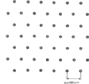
Fig. 2 is the plane graph that is used to explain the essence of embodiments of the invention;
Fig. 3 is the plane graph that is used to explain the essence of embodiments of the invention;
Fig. 4 is the plane graph of the essence of explanation embodiments of the invention;
Fig. 5 is the plane graph of the essence of explanation embodiments of the invention;
Fig. 6 is for explaining the plane graph of manufacturing according to the method for the GaN compound laser diode of the first embodiment of the present invention;
Fig. 7 is the schematic diagram that is presented near the exemplary distribution of the dislocation density the high defect area of the GaN substrate that uses in the first embodiment of the present invention;
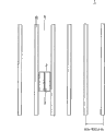
Fig. 8 is used to explain the plane graph of manufacturing according to the method for the GaN compound laser diode of the first embodiment of the present invention;
Fig. 9 is used to explain the cutaway view of manufacturing according to the method for the GaN compound laser diode of the first embodiment of the present invention;
Figure 10 is used to explain the cutaway view of manufacturing according to the method for the GaN compound laser diode of the first embodiment of the present invention;
Figure 11 is used to explain the cutaway view of manufacturing according to the method for the GaN compound laser diode of the first embodiment of the present invention;
Figure 12 is used to explain the cutaway view of manufacturing according to the method for the GaN compound laser diode of the second embodiment of the present invention;
Figure 13 is presented at the schematic diagram of manufacturing according to the edge by cutting apart the chip that obtains in the method for second embodiment of the present invention GaN compound laser diode;
Figure 14 is used to explain the plane graph of manufacturing according to the method for the GaN compound laser diode of the third embodiment of the present invention;
Figure 15 is used to explain the plane graph of manufacturing according to the method for the GaN compound laser diode of the fourth embodiment of the present invention;
Figure 16 is used to explain the plane graph of manufacturing according to the method for the GaN compound laser diode of the fifth embodiment of the present invention;
Figure 17 is used to explain the plane graph of manufacturing according to the method for the GaN compound laser diode of the sixth embodiment of the present invention;
Figure 18 is used to explain the plane graph of manufacturing according to the method for the GaN compound laser diode of the seventh embodiment of the present invention;
Figure 19 is for showing the cutaway view by the GaN compound laser diode of making according to the method for the seventh embodiment of the present invention;
Figure 20 is used to explain the plane graph of manufacturing according to the method for the GaN compound laser diode of the eighth embodiment of the present invention;
Figure 21 is for showing the cutaway view by the GaN compound laser diode of making according to the method for the eighth embodiment of the present invention;
Figure 22 is used to explain the plane graph of manufacturing according to the method for the GaN compound laser diode of the ninth embodiment of the present invention;
Figure 23 is used to explain the plane graph of manufacturing according to the method for the GaN compound laser diode of the tenth embodiment of the present invention;
Figure 24 is used to explain the plane graph of manufacturing according to the method for the GaN compound laser diode of the tenth embodiment of the present invention;
Figure 25 is used to explain the plane graph of manufacturing according to the method for the GaN compound laser diode of the 11st embodiment of the present invention;
Figure 26 is used to explain the plane graph of manufacturing according to the method for the GaN compound laser diode of the 12nd embodiment of the present invention;
Figure 27 is used to explain the plane graph of manufacturing according to the method for the GaN compound laser diode of the 13rd embodiment of the present invention;
Figure 28 is used to explain the plane graph of manufacturing according to the method for the GaN compound laser diode of the 14th embodiment of the present invention;
Figure 29 is used to explain the plane graph of manufacturing according to the method for the GaN compound laser diode of the 15th embodiment of the present invention;
Figure 30 is used to explain the plane graph of manufacturing according to the method for the GaN compound laser diode of the 16th embodiment of the present invention;
Figure 31 is used to explain the plane graph of manufacturing according to the method for the GaN compound laser diode of the 16th embodiment of the present invention;
Figure 32 is used to explain the plane graph of manufacturing according to the method for the GaN compound laser diode of the 17th embodiment of the present invention;
Figure 33 is used to explain the plane graph of manufacturing according to the method for the GaN compound laser diode of the 18th embodiment of the present invention;
Figure 34 is used to explain the plane graph of manufacturing according to the method for the GaN compound laser diode of the 19th embodiment of the present invention;
Figure 35 is used to explain the plane graph of manufacturing according to the method for the GaN compound laser diode of the 20th embodiment of the present invention; And
Figure 36 is used to explain the plane graph of manufacturing according to the method for the GaN compound laser diode of the 21st embodiment of the present invention.
Embodiment
What below explain is with reference to the accompanying drawings embodiments of the invention.The common Reference numeral of same or convertible part sign is described in the accompanying drawing of described embodiment at all.
Shown in Figure 1A, the embodiment that below explains show for use comprise the regional A that determines monocrystalline and have crystallization property different with regional A and with the situation of the area B of form periodic arrangement in regional A on island, and the situation that on substrate, forms the substrate of semiconductor device. this area B penetrates substrate. this zone aspect crystalline quality than described area difference, though and comprise more megacryst defective. Figure 1B shows along making area B present the cutaway view that nearest straight line obtains mutually. each area B has polygon arbitrarily pyramidal shape usually, for the sake of simplicity, what Fig. 1 showed is their (identical hereinafter) of cylinder form. when making semiconductor laser, thereby the semiconductor layer of component devices structure is by metal organic-matter chemical gas deposition (MOCVD), the hydrogen vapour phase epitaxial growth, halide vapour phase epitaxial growth (HVPE) so or similar approach on substrate, grow., step of formation electrode by further necessity etc., and utilize cleavage to cut apart them thereafter, cut apart this substrate and semiconductor layer thereon becomes chip, for example, obtain the semiconductor device of expecting.
In this manufacturing process, the crystal defect of base substrate is delivered on the semiconductor layer of growth thereon.Therefore, the semiconductor layer that is deposited on the device zone of inclusion region B will be by this defective effect, and character is poor.For example, under the situation that is light-emitting diode or semiconductor laser, if those defectives exist at its emitting area, so will destroy its emission characteristic and reliability.Therefore, in order to prevent that to emitting area the adverse effect from area B of active area is used following technology more widely.
(1) when design apparatus, the cycle decision that its dimension reference area B is arranged.
For example, when area B was 400 μ m with the centre distance of the equally spaced as shown in Figure 2 periodic arrangement of hexagonal lattice mode and nearest two area B, each device zone definitions was 400 * 346 μ m rectangular shapes.Be worth 346 μ m and equal 400 μ m * (3
1/2/ 2).
(2) determine this device zone of position assurance in each device zone not to be positioned at substantially on any area B, that is, guarantee that the device zone does not comprise area B substantially.
Each installs the zone, and it is for rectangle and be of a size of 400 * 346 μ m, for example, separately becomes chip by cutting apart substrate along the dotted line in Fig. 3.Therefore, this area B allows to be present on the end face or angle of each semiconductor device.
(3) when design apparatus, the determining positions of the active area in device is not for being positioned on any area B.
When device was semiconductor laser, its emitting area in most of the cases was bar shaped.In this case, the structure of semiconductor laser is designed to guarantee that this is not positioned on any area B.The example of such layout of Fig. 4 show bar.
By following as this technology and the program in (3) in (1), each device zone can be defined in the position of the adverse effect of the area B of avoiding having more defectives wittingly.
When this device was semiconductor laser, extra care guaranteed that the cavity edge of its emitting area is not positioned on any area B when design apparatus zone and apparatus structure especially.
Under the situation of semiconductor laser, the end face of chip is as its surface, chamber.Therefore, if overlap as the part of the minute surface in chamber and area B with many crystal defects as shown in Figure 5, will lose laser characteristics so.Therefore, when the minute surface part that is designed to guarantee the chamber did not overlap with area B, the position of the emitting area on substrate and the regional position of device were determined.
In above project (1), being of a size of 400 * 346 μ m rectangular shapes is an example, can select any other size and dimension to satisfy as the condition in project (2) and (3).
Below will explain the first embodiment of the present invention.In first embodiment, the GaN compound laser diode forms by growing GaN compound semiconductor layer on the GaN substrate, and wherein the area B of being made up of the crystal with high average dislocation density is arranged in regularly by among the regional A with harmonic(-)mean dislocation density crystal.
Fig. 6 is presented at the perspective view of plane graph .GaN substrate 1 of the GaN substrate that uses among first embodiment and cutaway view as shown in Figure 1A and the 1B. and this GaN substrate 1 is for having the n type substrate of (0001) face (C-face) orientation. still, this GaN substrate 1 can be the R-face, A-face or M-planar orientation. in GaN substrate 1, the area B of forming by crystal with high average dislocation density with hexagonal lattice form periodic arrangement in having the regional A of low-dislocation-density. in this case, the straight line that connects nearest two area B and GaN<1-100〉orientation or its is of equal value consistent. as selection, connect nearest two area B straight line can with GaN<11-20 orientation or its of equal value consistent. the thickness that area B penetrates GaN substrate 1.GaN substrate 1 for example is that the dotted line of 200~600 μ m. in Fig. 6 only shows the relative position relation that is used between the B of elongated area, and they are not the true lines (identical hereinafter) of (being of practical significance).
For example, the cycle of the arrangement of area B (distance between the center of two nearest area B) is 400 μ m, and the diameter of each area B is 20 μ m.The average dislocation density of zone A is 2 * 10
6Cm
-2, and the average dislocation density of area B is 1 * 10
8Cm
-2Fig. 7 is presented at their centers example of the distribution of the dislocation density of area B in the radial direction.
This GaN substrate 1 for example can be made by using the following mode of crystal technique.
Thereby the basic mechanism that is used to make the crystal growth of GaN substrate 1 is to make it be grown to the surface of being made up of facet with inclination and continued growth dislocation transmission and focus on presumptive area when keeping this faceted inclined surface.Zone with faceted growth is because the mobile low-density defect area that becomes of dislocation.Faceted tilting zone than lower part in, growth lasts till and comprises having the high density of defects zone of knowing the border.Dislocation focuses among zone boundary with high-density region or they, and disappears or pile up at there.
Depend on the shape in high density of defects zone, facet presents difformity.At defect area is under the situation of examples of dot shaped, and facet centers on this round dot as the bottom, and forms the depression of being made up of facet.At defect area is under the situation of bar shaped, faceted inclined surface be formed on as on the relative both sides of the bar of the lowest point with regard to two planes of the downward prism in image position.
After this, the top surface of grown layer is used so that it is smooth by cutting and polishing.Therefore, this GaN substrate 1 is ready to use as substrate.
This high density of defects zone can have some different conditions.For example, they can be polycrystalline.In one case, they can be monocrystal, but it is for around its density regions being slight inclination.In another case, their C axle can be for putting upside down for the low-density defect area around it.In this mode, the high density of defects zone has clearly the border and differentiates around them.
By keeping the growth in high density of defects zone, thus can growth substrates and bury facet around in the high density of defects zone and do not keep those facets.
The high density of defects zone can be pre-formed seed and produce by the position that should form in the high density of defects zone, this high density of defects zone utilizes the crystal growth of GaN on base substrate to form.Form layer amorphous or polycrystalline as these seeds.Therefore, by growing GaN thereon, the high density of defects zone can just in time form in the zone of seed.
Below explain the concrete manufacture method of this GaN substrate.At first, preparation base substrate.This base substrate can be selected from various substrates.Can be typical Sapphire Substrate.But, for the removal in the step afterwards, the preferred GaAs substrate of removing easily that uses.So planting for example SiO on the base substrate
2The seed of film.This seed for example can be examples of dot shaped or bar shape.The seed of predetermined quantity can regularly arrangedly form.More particularly, in this case, this seed forms with the arrangement mode corresponding to as shown in Figure 6 arrangement.After this, GaN is for example long thick by hydride vapor-phase epitaxy growth (HVPE).As a result, the facet corresponding to the pattern of seed occurs on the surface of the thick GaN layer that obtains by growth.When this seed has the pattern of round dot, form regularly by the depression of facet manufacturing.When seed presents the pattern of bar shaped, occur as the facet of prism.
After this, remove this base substrate, and utilize cutting and polishing that the top surface of thick GaN layer is flattened.As a result, obtain GaN substrate 1.The thickness of GaN substrate 1 can be as predetermined deciding.
This GaN substrate 1 has the main surface of C plane as it as explained above, and high density of defects preliminary dimension, the regularly arranged zone that comprises examples of dot shaped (or bar shape) wherein, also be area B. the crystal region of the remaining area except area B, also be regional A, have the dislocation density lower than area B.
In first embodiment, (single part is limited by heavy line) the device zone 2 that illustrates geometry at location definition shown in Figure 7 on substrate shown in Figure 11.So, form the GaN compound semiconductor layer of laser structure and on GaN substrate 1, grow, and, form laser structure by forming step and other necessary step of laser bar shaped.After this, have laser structure GaN substrate 1 thereon, be divided into the GaN compound laser diode chip of separation by cutting apart this substrate along the boundary line in single assembly zone 2.
In Fig. 8, black rectangle is corresponding to single GaN compound laser diode, and shows laser strip 3 corresponding to the position of emitting area by its straight line of core.By the rectangle of solid line and dotted line limit and the dotted line that prolongs therefrom corresponding to laser strip 4, and long side of laser strip 4 is corresponding to cavity edge.
In the example of Fig. 8, the GaN compound laser diode is of a size of for example 600 * 346 μ m.Substrate is divided into the GaN compound laser diode of this size of separation by not cutting apart substrate by the straight line (being parallel to the short side of laser) of area B along the straight line of join domain B (length direction of laser) in the horizontal direction and in vertical direction.
In this case, area B can only be positioned on the side surface than a long side of each GaN compound laser diode.Therefore, by design this device make they laser strip 3 each near the straight line of the mid point of shorter side, extend, prevent the influence of area B to emitting area.
The chamber minute surface is formed on by utilize the edge of the substrate that cleavage or similar approach cut apart along the vertical straight line in Fig. 8.Because these straight lines are not by any area B, the chamber minute surface is not by the influence of the dislocation in area B.Therefore, can obtain the outstanding and GaN compound laser diode that reliability increases of emission characteristic.
The concrete structure of below explaining typical GaN compound laser diode with and an example of manufacturing process.Here suppose that this GaN compound laser diode has ridge structure and SCH structure (separating sealing heterostructure (separate confinement heterostructure))
As shown in Figure 9, G for example the top surface of aN substrate 1 clean to clean by heat.After this, n type GaN resilient coating 5, n type AlGaN cover (clad) layer 6, n type GaN optical waveguide layers 7, have plain Ga
1-xIn
xN/Ga
1-yIn
yThe active layer 8 of N multi-quantum pit structure, plain InGaN degenerate and prevent that layer 9, p type AlGaN block layer (cap layer) 10, p type GaN optical waveguide layers 11, p type AlGaN cover layer 2 and p type GaN contact layer 13 from utilizing the MOCVD epitaxial growth on GaN substrate 1.
This n type GaN resilient coating 5 for example is that 0.05 μ m is thick, and for example mixes Si and mix as n.This n type AlGaN cover layer 6 is that 1.0 μ m are thick, and for example mixes Si and mix as n.Its Al composition can be for example 0.08.This n type optical waveguide layers 7 is thick for for example 0.1 μ m, and for example mixes Si and mix as n.Has the Ga of plain multi-quantum pit structure
1-xIn
xN/Ga
1-yIn
yIn the active layer 8 of N, each Ga
1-xIn
xYet the N layer is thick and each Ga of x=0.14 of 3.5nm as the trap layer
1-yIn
yThe N layer is the thick and y=0.02 of 7nm as barrier layer.This active layer 8 comprises three trap layers.
Plain InGaN degenerates and prevents that layer 9 has gradient (graded) structure, wherein the In composition little by little, monotonously from the surface that contact with active layer 8 to surfaces minimizings that contact with p type AlGaN block layer 9.The In composition on the surface that contacts with active layer 8 equals the Ga as the barrier layer of active layer 8
1 -yIn
yThe In composition y of N layer.With the composition of the In on p type AlGaN block layer 10 surface that contact is zero.Plain InGaN degeneration prevents that the thickness of layer 9 from for example can be 20nm.
This p type AlGaN block layer 10 for example is that 10nm is thick, and for example mix magnesium (Mg) as the composition of the Al of its p type doping .P type AlGaN block layer 10 for example for 0.2.p type AlGaN block layer 10 not single-pass cross and remove In when p type AlGaN block layer and the p type GaN optical waveguide layer growth and have the function that prevents active layer 8 degenerations and also have the function that prevents that charge carrier (electronics) from overflowing from active layer. this p type GaN optical waveguide layers for example is that 0.1 μ m is thick, and for example mixing the p type doping of Mg as it. this p type AlGaN block layer 12 for example is that 0.5 μ m is thick, and for example mixes the p type doping of Mg as it. the Al composition of layer 12 can for example be that 0.1 μ m is thick for this p type of 0.08. GaN contact layer 13 for example.
The source material that is used for these GaN compound semiconductor layers for example can be the trimethyl gallium ((CH as the material of Ga
3)
3Ga, TMG), as the trimethyl aluminium ((CH of the material of Al
3)
3Al, TMA), as the trimethyl indium ((CH of the material of In
3)
3In is TMI) and as the NH of the material of N
3Vector gas for example can be H
2Alloy for example can be monosilane (SiH as n type alloy
4), can be bis=methylcyclopentadienile magnesium ((CH as p type alloy
3C
5H
4)
2Mg) or bis=cyclopentadienile magnesium ((C
2H
5)
2Mg).
In next step, as explained above have the c plane sapphire substrate that these GaN compound semiconductor layers grow on it and remove from MOCVD equipment.So, at SiO
2The film (not shown) for example is that 0.1 μ is thick, utilizes for example CVD on the whole surface of p type GaN contact layer 13, and vacuum evaporation or sputter form, corresponding to the corrosion-resisting pattern (not shown) of the predetermined profile of ridge part shape at SiO
2Utilize photoetching to form on the film.Then use these corrosion-resisting patterns as mask, by using based on the etching liquid wet etching of hydrofluoric acid or by using for example CF
4Or CHF
3The RIE etching SiO optionally of the etching gas that comprises fluorine
2Film becomes the pattern corresponding to ridge part.
Then use SiO
2Film is as mask, and layer below for example utilizes the RIE etching, down to the desired depth of p type AlGaN cover layer 12 in order to obtain at<1-100 the ridge as shown in figure 10 14 that extends of direction.Ridge 14 for example is that 3 μ m are wide.In this RIE, for example use based on chlorine as etching gas.
In next step technology, at the SiO that removes as etching mask
2After the film, the thick SiO of 0.3 μ m for example
2The dielectric film 15 of film for example utilizes CVD, vacuum evaporation or sputter to be formed on the whole surface of substrate.This insulation film 15 is as electric insulation and surface protection.
In next step technology, local covering forms by photoetching except the corrosion-resisting pattern (not shown) of the dielectric film 15 in p lateral electrode zone.
After this, use this corrosion-resisting pattern, the 15a of dielectric film 15 etchings becoming window as mask.
After this, when keeping corrosion-resisting pattern, for example Pd film, Pt film and the Au film Pd film, Pt film and the Au film that utilize for example vacuum coating to be deposited on entire substrate surface and corrosion-resisting pattern and stack in succession comes along except that (peeling off).The result obtains the p lateral electrode 16 that the window 15a by dielectric film 15 contacts with p type GaN contact layer 13.Pd film, Pt film and the Au film of forming p lateral electrode 16 for example be respectively 10nm, 100nm and 300nm thick.After this, implementing fusion makes p lateral electrode 16 become ohmic contact.
In next step technology, for example Ti film, Pt film and the Au film lower surface of utilizing for example vacuum evaporation to continue to be deposited on GaN substrate 1 has the n lateral electrode of Ti/Pt/Au structure in order to formation. Ti film, Pt film and the Au film of forming n lateral electrode 17 for example be respectively 10nm, 50nm and 100nm thick. after this, implement fusion and making n lateral electrode 17 become ohmic contact.
After this, form laser structure GaN substrate 1 and be divided into laser strip in order to form relative cavity edge by cutting apart it along the boundary line cleavage in device zone 2 by above-mentioned steps.In addition, after these cavity edges of coating, each bar is cut apart it by cleavage or similar approach and is divided into chip.
As a result, finish the GaN compound laser diode of extension as shown in figure 11 with ridge structure and SCH structure.
As explained above, according to first embodiment, each device zone 2 is defined in and comprises having and make each device zone 2 not comprise area B substantially on higher average dislocation density and the GaN substrate 1 with hexagonal lattice area B of periodic arrangement in having than the regional A of harmonic(-)mean dislocation density, and the GaN compound semiconductor layer that will form laser structure is grown on GaN substrate 1.Therefore, promptly convenient defectives, for example dislocation from the area B transmission of GaN compound semiconductor layer 1, can not be subjected to these defect influence at this GaN compound semiconductor layer that installs on the zone 2.After the growth of GaN compound semiconductor layer, and by further forming ridge, p lateral electrode 16, n lateral electrode 17 and other step, the GaN substrate 1 that has formed laser structure is divided into GaN compound laser diode chip separately by separating it along the boundary line in device zone.Therefore, any GaN compound laser diode chip does not comprise the dislocation of transmitting from GaN substrate 1 substantially.As a result, realize the GaN compound laser diode that luminosity is outstanding, that reliability increases and the life-span prolongs.
In addition, in first embodiment, the InGaN that do not mix degenerates and to prevent that layer 9 from forming and contact with active layer 8, and p type AlGaN block layer 10 forms with the InGaN degeneration of not mixing and prevents that layers 9 contact.Therefore, the InGaN that do not mix degenerates and to prevent that layer 9 from alleviating the stress that applies to active layer 8 from p type AlGaN block layer 10 widely.Simultaneously, prevent from effectively to be distributed to active layer 7 as the Mg of the p type alloy of p type layer.
Below explain the second embodiment of the present invention.
As shown in figure 12, in a second embodiment, short side in rectangular devices zone 2 and long side, it forms the boundary line in each device zone 2, all is the central line of join domain B unlike first embodiment.Same here, laser strip 3 is positioned at and connects on the line of single assembly zone 2 than the mid point of short side.In this mode, can prevent the influence for generation area of area B.
The difference of second embodiment and first embodiment is that this boundary line is the straight line at the center of join domain B by cutting apart substrate-like coelosis minute surface along the boundary line cleavage in device zone 2.
Having more, the area B of multidigit mistake is considered to the easier fracture than regional A.Therefore, when substrate when the straight line of join domain B is cut apart, area B plays perforation, and also cleavage clearly of regional A.In this case, the area B that appears at the edge has many dislocations, and will always can not flatten.But the regional A that appears between the area B becomes smooth on the edge.Such marginal texture schematically as shown in figure 13.
Here the end face of laser strip 2 need be flattened just.Therefore, as shown in figure 12, in the position of opposed area B, the area B that appears at end face can not have a negative impact to emission characteristic for each device zone definitions.
Other characteristics of second embodiment are identical with first embodiment.Therefore omit other explanations.
Second embodiment guarantees the same advantage as first embodiment.
Then explain the 3rd embodiment of this aspect.
In the 3rd embodiment, as shown in figure 14, the area B of making by crystal with higher average dislocation density with the form periodic arrangement of rectangular lattice having among the regional A than the harmonic(-)mean dislocation density on GaN substrate 1. have the single rectangle of area B and be defined as single assembly zone 2. in this case in its four corners, each straight line that connects two nearest adjacent areas B at longitudinal direction of rectangle and GaN<1-100 direction is consistent, each the straight line of two nearest adjacent areas B of the connection of lacking a side of rectangle and GaN<11-20 direction is consistent.
Area B for example is 600 μ m at the interval of the longitudinal direction of rectangular lattice, and the interval of area B on the direction of short side that is parallel to rectangular lattice for example is 400 μ m.In this case, each device zone 2 is of a size of 600 * 400 μ m.
The laser strip 3 in each device zone is positioned on the straight line of the mid point that connects the shorter side that faces toward.
Other characteristics of the 3rd embodiment are identical with first embodiment.Therefore omit other explanations.
The 3rd embodiment guarantees the same advantage as first embodiment equally.
Then explain the fourth embodiment of the present invention.
In the 4th embodiment, as shown in figure 15, the similar form periodic arrangement in the regional A of GaN substrate 1 of area B with hexagonal lattice to first embodiment.But, the difference of the 4th embodiment and first embodiment be to comprise have the average dislocation density of the centre between the average dislocation density of the average dislocation density of regional A and area B and insert regional A and when the zone C between the area B.More particularly, the average dislocation density of regional A is 2 * 10
6Cm
-2Or bigger, the average dislocation density of area B is 1 * 10
8Cm
-2Or bigger, and the average dislocation density of zone C is than 1 * 10
8Cm
-2Little and than 2 * 10
6Cm
-2Greatly.The interval of area B (distance at the center of two nearest adjacent areas B) for example is 300 μ m, and the diameter of each area B is 20 μ m.The diameter of each zone C for example is 120 μ m.
In this case, unlike first embodiment, each rectangular devices zone 2 than long side surface and shorter side, it defines its boundary line, all is the straight line at the center of join domain B.Each device zone all is size 600 * 260 μ m in each rectangular devices zone 2.Same here, laser strip 3 is positioned on the line of mid point of the shorter side that connects single assembly zone 2.But in this embodiment, laser strip 3 is not overlapping with area B and zone C.In this mode, can prevent area B and C influence to emitting area.
Other characteristics of the 4th embodiment are identical with first embodiment.Therefore omit other explanations.
The 4th embodiment guarantees the same advantage as first embodiment equally.
Then explain the fifth embodiment of the present invention.
In the 5th embodiment, as shown in figure 16, area B with the form of hexagonal lattice in the regional A of GaN substrate 1 to the similar periodic arrangement of first embodiment.But, the difference of the 5th embodiment and first embodiment be to comprise have the average dislocation density of the centre between the average dislocation density of the average dislocation density of regional A and area B and insert regional A and when the zone C between the area B.More particularly, the average dislocation density of regional A is 2 * 10
6Cm
-2Or bigger, the average dislocation density of area B is 1 * 10
8Cm
-2Or bigger, and the average dislocation density of zone C is than 1 * 10
8Cm
-2Little and than 2 * 10
6Cm
-2Greatly.The interval of area B (distance at the center of two nearest adjacent areas B) for example is 400 μ m, and the diameter of each area B is 20 μ m.The diameter of each zone C for example is 120 μ m.
In this case, unlike first embodiment, as the device zone 2 of first example be defined as the boundary line that makes corresponding to the shorter side in rectangular devices zone 2 be join domain B the center straight line and connect the straight line of the straight line 23 μ m of nearest two adjacent area B corresponding to rectangular devices zone 2 for distance than the boundary line of long side surface.In this example, device zone 2 for example is 400 * 300 μ m.Same at this, laser strip 3 is positioned on the line of mid point of the shorter side that connects single assembly zone 2.But in this embodiment, laser strip 3 is not overlapping with area B and zone C.In this mode, can prevent area B and C influence to emitting area.
On the other hand, as the device zone 2 of the twoth example be defined as make corresponding to the boundary line of the long side in rectangular devices zone 2 apart from connect two nearest adjacent areas B at<1-100 straight line 23 μ m on the direction, and corresponding to the boundary line of the shorter side of rectangle apart from connecting two nearest adjacent areas B at<11-20 straight line 100 μ m. on the direction are same at this, device zone 2 for example is 400 * 300 μ m, and laser strip 3 is positioned on the line of mid point of the shorter side that connects single assembly zone 2. but in this embodiment, laser strip 3 is not overlapping with area B and zone C. in this mode, can prevent area B and C influence to emitting area.
Other characteristics of the 5th embodiment are identical with first embodiment.Therefore omit other explanations.
The 5th embodiment guarantees the same advantage as first embodiment equally.
Then explain the sixth embodiment of the present invention.
In the 6th embodiment, as shown in figure 17, area B with the form of hexagonal lattice in the regional A of GaN substrate 1 to the similar periodic arrangement of first embodiment.But the difference of the 6th embodiment and first embodiment is between the center of nearest adjacent areas B at<1-100〉span of direction is the twice of the length of the shorter side in each rectangular devices zone 2, also, 700 μ m for example.The boundary line that defines the shorter side in each device zone 2 is positioned at each at<11-20〉yet direction connects definition on the straight line of nearest adjacent areas B is positioned at each at<1-100 than the boundary line of long side surface〉direction connects on the straight line of nearest adjacent areas B.In this case, the size in each device zone 2 for example is 606 * 350 μ m.Laser strip 3 is positioned on the line of mid point of the shorter side that connects single assembly zone 2, does not overlap with any area B.In this mode, can prevent the influence of area B to emitting area.
Other characteristics of the 6th embodiment are identical with first embodiment.Therefore omit other explanations.
The 6th embodiment guarantees the same advantage as first embodiment equally.
Then explain the seventh embodiment of the present invention.
In the 7th embodiment, as shown in figure 18, two laser strip 3 are parallel to each other and are formed in each device zone 2.Figure 19 shows by cutting apart the GaN compound laser diode chip that obtains along the boundary line in device zone 2.
Other characteristics of the 7th embodiment are identical with first embodiment.Therefore omit other explanations.
The 7th embodiment guarantees in multi beam GaN compound laser diode as the same advantage of first embodiment equally.
Then explain the eighth embodiment of the present invention.
In the 8th embodiment, as shown in figure 20, laser strip 3 is similarly constructed with first embodiment in each device zone.But in this embodiment, laser strip 3 to the first embodiment's is much wide.More particularly, when the length of short side in each rectangular devices zone 2 is the diameter of a and each area B when being d, the Breadth Maximum of each laser strip 3 is a-d.But laser strip 3 is preferably left area B at least 1 μ m.Amount to, the actual Breadth Maximum of laser strip 3 is a-d-2 μ m.For example, as a=346 μ m and d=20 μ m, be limited to 346-20-2=324 μ m on the width of laser strip 3.In preferred example, laser strip 3 can be wide for 200 μ m.Figure 21 is presented in that example by cutting apart the GaN compound laser diode chip that obtains along the boundary line in device zone 2.
Other characteristics of the 8th embodiment are identical with first embodiment.Therefore omit other explanations.
The 8th embodiment guarantees the same advantage as first embodiment equally.
Then explain the ninth embodiment of the present invention.
Figure 22 is the plane graph that is presented at the GaN substrate that uses among the 9th embodiment.
In the 9th embodiment, as shown in figure 22, the device zone definitions is not for comprising area B in laser strip 3.This laser strip 3 is left area B at least 50 μ m.In this case, illustrational here device 2 causes overlapping two area B.
Other characteristics of the 9th embodiment are identical with first embodiment.Therefore omit other explanations.
The 9th embodiment guarantees the same advantage as first embodiment equally.
Then explain the tenth embodiment of the present invention.
Figure 23 is the plane graph that is presented at the GaN substrate that uses among the tenth embodiment.This GaN substrate 1 is for having the n type substrate of C planar orientation.But, as selecting this GaN substrate can have R plane, A plane or M planar orientation.In this GaN substrate 1, the area B of being made up of the crystal with higher average dislocation density is at<11-20〉direction is with all period interval of for example 400 μ m and be orthogonal to<11-20<1-100 direction is spaced by having among the regional A that forms than the crystal of harmonic(-)mean dislocation density with for example cycle of 20~100 μ m.Right<11-20〉and<1-100〉direction, can vice versa.
In the tenth embodiment, device zone 2 is defined as and makes a pair of end face of parallel laser bar 3 lay respectively at<1-100〉the adjacent row of the area B of direction, and laser strip 3 is near the center in the zone between those row of area B.In this mode, any device zone 2 does not comprise any row of area B substantially.
Other characteristics of the tenth embodiment are identical with first embodiment.Therefore omit other explanations.
The tenth embodiment guarantees the same advantage as first embodiment equally.
Then explain the 11st embodiment of the present invention.
As shown in figure 25, the 11 embodiment uses and GaN substrate 1 similar in the tenth embodiment.But the end face that is parallel to each laser strip that is that is different from the tenth embodiment is positioned at area B at<1-100〉surface of the row of direction but opposing ends extends along the line of the next line that leaves area B.Same at this, any device zone 2 does not comprise any row of area B substantially.
Other characteristics of the 11 embodiment are identical with the tenth and first embodiment.Therefore omit other explanations.
The 11 embodiment guarantees the same advantage as first embodiment equally.
Then explain the 12nd embodiment of the present invention.
As shown in figure 26, the 12 embodiment uses and GaN substrate 1 similar in the tenth embodiment.But, be different from being that device zone 2 is defined as and making the opposing end faces be parallel to laser strip 3 all be positioned at area B of the tenth embodiment at<1-100〉between the adjacent row of direction and laser strip 3 be located near the centre in the zone between those row of area B.Same at this, any device zone 2 does not comprise any row of area B substantially.
Other characteristics of the 12 embodiment are identical with the tenth and first embodiment.Therefore omit other explanations.
The 12 embodiment guarantees the same advantage as first embodiment equally.
Then explain the 13rd embodiment of the present invention.
As shown in figure 27, the 13 embodiment uses and GaN substrate 1 similar in the tenth embodiment.But, one of a pair of end face that is to be parallel to laser strip that is different from the tenth embodiment is positioned at area B at<1-100〉row of direction and between the next one two row of other end in area B, and laser strip 3 is extended along nearest row 50 μ m that leave area B or more line.In this mode, each device zone 2 comprises the delegation of area B.
Other characteristics of the 13 embodiment are identical with the tenth and first embodiment.Therefore omit other explanations.
The 13 embodiment guarantees the same advantage as first embodiment equally.
Then explain the 14th embodiment of the present invention.
As shown in figure 28, the 14 embodiment uses and GaN substrate 1 similar in the tenth embodiment.But, one of the end face that is to be parallel to laser strip that is different from the tenth embodiment is along leaving area B at<1-100〉line of the row of direction extend and the next one two row of other end in area B between extend, and laser strip 3 is extended along nearest row 50 μ m that leave area B or more line.In this mode, each device zone 2 comprises the delegation of area B.
Other characteristics of the 14 embodiment are identical with the tenth and first embodiment.Therefore omit other explanations.
The 14 embodiment guarantees the same advantage as first embodiment equally.
Then explain the 15th embodiment of the present invention.
Figure 29 is the plane graph that is presented at the GaN substrate 1 that uses among the 15 embodiment.
In the 15 embodiment, as shown in figure 29, each laser strip 3 is extended near the center in the zone between the adjacent lines of area B, and a pair of end face that is parallel to laser strip 3 is extending between the row of the front of area B and in appearance and near the center in the zone between the row of their adjacent areas B.
Other characteristics of the 15 embodiment are identical with the tenth and first embodiment.Therefore omit other explanations.
The 15 embodiment guarantees the same advantage as first embodiment equally.
Then explain the 16th embodiment of the present invention.
Figure 30 is the plane graph that is presented at the GaN substrate 1 that uses among the 16 embodiment.This GaN substrate 1 is for n type substrate and have the C planar orientation.But GaN substrate 1 can be R plane, A plane or M plane domain.In GaN substrate 1, form by crystal with high average dislocation density and at<1-100 the linearly extended area B of direction is at quadrature<1-100 direction<11-20 direction for example arranges with the gap periods of 400 μ m.But<11-20〉with<1-100 direction, can vice versa.
In the 16 embodiment, as shown in figure 31, device zone 3 be defined as make a pair of end face that is parallel to each laser strip 3 on the area B and laser strip 3 be located near the zone between those area B.In this case, any device zone 2 does not comprise area B substantially.
Other characteristics of the 16 embodiment are identical with first embodiment.Therefore omit other explanations.
The 16 embodiment guarantees the same advantage as first embodiment equally.
Then explain the 17th embodiment of the present invention.
Shown in figure 32, the 17 embodiment uses and GaN substrate 1 similar in the 16 embodiment.But one of end face that is to be parallel to each laser strip 3 that is different from the 16 embodiment is positioned at that one of area B goes up and extend along the line of the area B of leaving any straight line the other end.Same at this, any device zone 2 does not comprise area B substantially.
Other characteristics of the 17 embodiment are identical with the 16 and first embodiment.Therefore omit other explanations.
The 17 embodiment guarantees the same advantage as first embodiment equally.
Then explain the 18th embodiment of the present invention.
As shown in figure 33, the 18 embodiment uses and GaN substrate 1 similar in the 16 embodiment.But what be different from the 16 embodiment is that device zone 2 is defined as the feasible opposing end faces that is parallel to each laser strip 3 and all extends near the center in the zone between those area B in extension of the zone between the adjacent areas B and laser strip 3.Same at this, any device zone 2 does not comprise area B substantially.
Other characteristics of the 18 embodiment are identical with the 16 and first embodiment.Therefore omit other explanations.
The 18 embodiment guarantees the same advantage as first embodiment equally.
Then explain the 19th embodiment of the present invention.
As shown in figure 34, the 19 embodiment uses and GaN substrate 1 similar in the 16 embodiment.But one of the end face that is to be parallel to each laser strip 3 that is different from the 16 embodiment is extending in the zone of opposing end faces between next two area B on one of area B and laser strip 3 is extended along the line that leaves one of nearest area B 50 μ m at least.In this case, each device zone 2 comprises an area B.
Other characteristics of the 19 embodiment are identical with the 16 and first embodiment.Therefore omit other explanations.
The 19 embodiment guarantees the same advantage as first embodiment equally.
Then explain the 20th embodiment of the present invention.
As shown in figure 35, the 20 embodiment uses and GaN substrate 1 similar in the 16 embodiment.But one of the end face that is to be parallel to each laser strip 3 that is different from the 16 embodiment extends and extends in the zone of opposing end faces between next two area B and laser strip 3 is extended along the line that leaves one of nearest area B 50 μ m at least along the line that leaves one of nearest area B.In this case, each device zone 2 comprises an area B.
Other characteristics of the 20 embodiment are identical with the 16 and first embodiment.Therefore omit other explanations.
The 20 embodiment guarantees the same advantage as first embodiment equally.
Then explain the 21st embodiment of the present invention.
Figure 36 is the plane graph of the GaN substrate 1 that uses in the 21 embodiment.This GaN substrate 1 except area B for example GaN<11-20 direction with the gap periods ground of 200 μ m arrange think identical with the GaN substrate that in the 16 embodiment, uses.In this case, each device zone 2 comprises two linearity region B.
In the 21 embodiment, as shown in figure 36, each laser strip 3 be located at the zone between the adjacent areas B the center near, and a pair of end face that is parallel to laser strip 3 respectively between those area B and their extend in the zone between the adjacent areas B in appearance.
Other characteristics of the 21 embodiment are identical with the 16 and first embodiment.Therefore omit other explanations.
The 21 embodiment guarantees the same advantage as first embodiment equally.
So far, explained typical embodiment clearly.But the present invention is not limited to those embodiment, is also expecting various changes and modification based on technology idea of the present invention.
The embodiment in conjunction with above explanation for example mentions, value, structure, substrate, source material, the technology of numeral or similarly only be example can be selected any other suitable digital value, structure, substrate, source material, technology or similar in the place of needs.
For example, those embodiment have explained the ingredient n type layer that at first deposits the laser structure of conduct on substrate and have deposited p type layer afterwards.But the order of sedimentary deposit can be put upside down at first deposit p type layer on substrate and deposit n type layer then thereon.
In addition, those embodiment have explained as the GaN compound laser diode manufacturing that is applied to the SCH structure.But the present invention for example can be applied to the GaN compound laser diode of DH (double-heterostructure) structure and the manufacturing that is applied to the GaN compound light-emitting diode certainly.In addition, the present invention can be applied to the means of electronic transmission of using nitride III-V compound semiconductor, for example GaN compound F 17-hydroxy-corticosterone ETs and GaN heterojunction bipolar transistor (HBTs).
Aforesaid embodiment uses H
2Gas is as the vector gas that utilizes the MOCVD growth.But any other appropriate carriers gas, for example H
2With N
2Or the mist of He, Ar gas or similar gas.
Form cavity edge though aforesaid embodiment has explained by cleavage, cavity edge can form by the dry etching of for example RIE.
As described above, according to the present invention, the device zone definitions is on nitride III-V compound semiconductor substrate, the substrate of other Semiconductor substrate or any kind of makes the active area of device not comprise higher than the average dislocation density of first area substantially, average defect concentration second area high or the crystallographic property difference. therefore, even if dislocation or other defective are delivered to deposition in order to form the nitride III-V compound semiconductor layer of luminous device structure or other apparatus structure from second area, other semiconductor layer, perhaps on the layer of any other various types of materials, still guarantee not comprise dislocation or other defective substantially by cutting apart the chip that substrate obtains. the result, the present invention can realize that emission characteristic is outstanding, the semiconductor light-emitting apparatus that reliability strengthens and the life-span prolongs, perhaps other character is outstanding, the semiconductor device that reliability strengthens and the life-span prolongs, perhaps other various character are outstanding, the device that reliability strengthens and the life-span prolongs.
Claims (48)
1. a nitride III-V compound semiconductor layer that forms luminous device structure by growth on nitride III-V compound semiconductor substrate is made the method for semiconductor light-emitting apparatus, a plurality of second areas with second average dislocation density higher than first average dislocation density are arranged in regularly and are made by crystal and have in the first area of described first average dislocation density in described nitride III-V compound semiconductor substrate, and, C axle with respect to the described second area of C axle of described first area is what put upside down, and this method comprises:
Definition makes described device zone not comprise described second area substantially as the zone that finally is elected to be chip by the cutting substrate in device zone on nitride III-V compound semiconductor substrate.
2. according to the method for the described manufacturing semiconductor light-emitting apparatus of claim 1, wherein determine the size and the position in described device zone to make described device zone not comprise second area substantially.
3. according to the method for the described manufacturing semiconductor light-emitting apparatus of claim 1, wherein said second area periodic arrangement.
4. according to the method for the described manufacturing semiconductor light-emitting apparatus of claim 1, wherein said second area is with the form periodic arrangement of hexagonal lattice.
5. according to the method for the described manufacturing semiconductor light-emitting apparatus of claim 1, wherein said second area is with rectangular lattice form periodic arrangement.
6. according to the method for the described manufacturing semiconductor light-emitting apparatus of claim 1, wherein said second area is with square latticed form periodic arrangement.
7. according to the method for the described manufacturing semiconductor light-emitting apparatus of claim 1, wherein said device zone is a rectangle.
8. according to the method for the described manufacturing semiconductor light-emitting apparatus of claim 7, a pair of relative parallel sided in wherein said device zone is in<1-100〉direction, and another to relative parallel sided in<11-20 direction.
9. according to the method for the described manufacturing semiconductor light-emitting apparatus of claim 1, wherein said device zone is a square.
10. according to the method for the described manufacturing semiconductor light-emitting apparatus of claim 1, the distance between the center of two wherein nearest described second areas is 20 μ m or bigger.
11. according to the method for the described manufacturing semiconductor light-emitting apparatus of claim 1, the distance between the center of two wherein nearest described second areas is 50 μ m or bigger.
12. according to the method for the described manufacturing semiconductor light-emitting apparatus of claim 1, the distance between the center of two wherein nearest described second areas is 100 μ m or bigger.
13. according to the method for the described manufacturing semiconductor light-emitting apparatus of claim 3, the cycle of the arrangement of wherein said second area is 20 μ m or bigger.
14. according to the method for the described manufacturing semiconductor light-emitting apparatus of claim 3, the cycle of the arrangement of wherein said second area is 50 μ m or bigger.
15. according to the method for the described manufacturing semiconductor light-emitting apparatus of claim 3, the cycle of the arrangement of wherein said second area is 100 μ m or bigger.
16. according to the method for the described manufacturing semiconductor light-emitting apparatus of claim 1, wherein said second area penetrates described nitride III-V compound semiconductor substrate.
17. according to the method for the described manufacturing semiconductor light-emitting apparatus of claim 1, wherein each described second area has many arbitrarily prismatics.
18. according to the method for the described manufacturing semiconductor light-emitting apparatus of claim 1, insert between described first area and the described second area in the 3rd zone that wherein has three average dislocation density high and lower than described second average dislocation density than described first average dislocation density.
19. according to the method for the described manufacturing semiconductor light-emitting apparatus of claim 18, wherein said device zone definitions is for making described device zone not comprise described second area and described the 3rd zone substantially.
20. according to the method for the described manufacturing semiconductor light-emitting apparatus of claim 1, wherein each described second area has the diameter of from 10 to 100 μ m.
21. according to the method for the described manufacturing semiconductor light-emitting apparatus of claim 1, wherein each described second area has the diameter of from 20 to 50 μ m.
22. according to the method for the described manufacturing semiconductor light-emitting apparatus of claim 18, wherein each described the 3rd zone has the diameter than big 20 to the 200 μ m of diameter of each described second area.
23. according to the method for the described manufacturing semiconductor light-emitting apparatus of claim 18, wherein each described the 3rd zone has the diameter than big 40 to the 160 μ m of diameter of each described second area.
24. according to the method for the described manufacturing semiconductor light-emitting apparatus of claim 18, wherein each described the 3rd zone has the diameter than big 60 to the 140 μ m of diameter of each described second area.
25. according to the method for the described manufacturing semiconductor light-emitting apparatus of claim 1, the described average dislocation density of wherein said second area is five times of described first average dislocation density or more.
26. according to the method for the described manufacturing semiconductor light-emitting apparatus of claim 1, the described average dislocation density of wherein said second area is 1 * 10
8Cm
-2Or it is bigger.
27. according to the method for the described manufacturing semiconductor light-emitting apparatus of claim 1, the described average dislocation density of wherein said first area is 2 * 10
6Cm
-2Or littler, and the described average dislocation density of described second area is 1 * 10
8Cm
-2Or it is bigger.
28. according to the method for the described manufacturing semiconductor light-emitting apparatus of claim 18, the described average dislocation density of wherein said first area is 2 * 10
6Cm
-2Or littler, the described average dislocation density of described second area is 1 * 10
8Cm
-2Or bigger, and the described average dislocation density in described the 3rd zone is than 1 * 10
8Cm
-2Little and than 2 * 10
6Cm
-2Greatly.
29. according to the method for the described manufacturing semiconductor light-emitting apparatus of claim 1, the emitting area of wherein said semiconductor light-emitting apparatus leaves described second area at least 1 μ m.
30. according to the method for the described manufacturing semiconductor light-emitting apparatus of claim 1, the emitting area of wherein said semiconductor light-emitting apparatus leaves described second area at least 10 μ m.
31. according to the method for the described manufacturing semiconductor light-emitting apparatus of claim 1, the emitting area of wherein said semiconductor light-emitting apparatus leaves described second area at least 100 μ m.
32. according to the method for the described manufacturing semiconductor light-emitting apparatus of claim 18, the emitting area of wherein said semiconductor light-emitting apparatus does not comprise described second area and described the 3rd zone.
33. according to the method for the described manufacturing semiconductor light-emitting apparatus of claim 1, wherein described second area at least 1 μ m is left in the zone of passing through strip shaped electric poles supply drive current in described semiconductor light-emitting apparatus.
34. according to the method for the described manufacturing semiconductor light-emitting apparatus of claim 1, wherein described second area at least 10 μ m are left in the zone of passing through strip shaped electric poles supply drive current in described semiconductor light-emitting apparatus.
35. according to the method for the described manufacturing semiconductor light-emitting apparatus of claim 1, wherein described second area at least 100 μ m are left in the zone of passing through strip shaped electric poles supply drive current in described semiconductor light-emitting apparatus.
36. according to the method for the described manufacturing semiconductor light-emitting apparatus of claim 18, wherein the zone of passing through strip shaped electric poles supply drive current in described semiconductor light-emitting apparatus does not comprise described second area and described the 3rd zone.
37. according to the method for the described manufacturing semiconductor light-emitting apparatus of claim 1, the boundary line in wherein said device zone comprises the straight line of at least two adjacent second areas of connection.
38. according to the method for the described manufacturing semiconductor light-emitting apparatus of claim 1, the described nitride III-V compound semiconductor substrate that wherein has growth described nitride III-V compound semiconductor layer is thereon cut apart along the boundary line that comprises two adjacent second areas at least.
39. according to the method for the described manufacturing semiconductor light-emitting apparatus of claim 38, implement wherein said cutting apart by cleavage.
40. according to the method for the described manufacturing semiconductor light-emitting apparatus of claim 1, described second area at least 1 μ m is left in the boundary line in wherein said device zone.
41. according to the method for the described manufacturing semiconductor light-emitting apparatus of claim 1, the described nitride III-V compound semiconductor substrate that wherein has growth described nitride III-V compound semiconductor layer is thereon cut apart along the boundary line of leaving described second area 1 μ m at least.
42. according to the method for the described manufacturing semiconductor light-emitting apparatus of claim 41, implement wherein said cutting apart by cleavage.
43. according to the method for the described manufacturing semiconductor light-emitting apparatus of claim 1, wherein said nitride III-V compound semiconductor substrate is by Al
xB
yGa
1-x-y-zIn
zAs
uN
1-u-vP
vMake, wherein 0≤x≤1,0≤y≤1,0≤z≤1,0≤u≤1,0≤v≤1,0≤x+y+z<1 and 0≤u+v<1.
44. according to the method for the described manufacturing semiconductor light-emitting apparatus of claim 1, wherein said nitride III-V compound semiconductor substrate is by Al
xB
yGa
1-x-y-zIn
zN makes, wherein 0≤x≤1,0≤y≤1,0≤z≤1 and 0≤x+y+z<1.
45. according to the method for the described manufacturing semiconductor light-emitting apparatus of claim 1, wherein said nitride III-V compound semiconductor substrate is by Al
xGa
1-x-zIn
zN makes, wherein 0≤x≤1 and 0≤z≤1.
46. according to the method for the described manufacturing semiconductor light-emitting apparatus of claim 1, wherein said nitride III-V compound semiconductor substrate is made by GaN.
47. according to the method for the described manufacturing semiconductor light-emitting apparatus of claim 1, wherein said semiconductor light-emitting apparatus is a semiconductor laser.
48. according to the method for the described manufacturing semiconductor light-emitting apparatus of claim 1, wherein said semiconductor light-emitting apparatus is a light-emitting diode.
Applications Claiming Priority (3)
| Application Number | Priority Date | Filing Date | Title |
|---|---|---|---|
| JP315703/2001 | 2001-10-12 | ||
| JP2001315703A JP4290358B2 (en) | 2001-10-12 | 2001-10-12 | Manufacturing method of semiconductor light emitting device |
| PCT/JP2002/010323 WO2003034560A1 (en) | 2001-10-12 | 2002-10-03 | Method for fabricating semiconductor light emitting element, semiconductor light emitting element, method for fabricating semiconductor element, semiconductor element, method for fabricating element and element |
Related Child Applications (3)
| Application Number | Title | Priority Date | Filing Date |
|---|---|---|---|
| CNB2006101592952A Division CN100440556C (en) | 2001-10-12 | 2002-10-03 | Semiconductor light emitting device and device |
| CNB2006101592967A Division CN100440557C (en) | 2001-10-12 | 2002-10-03 | Semiconductor light emitting device and device |
| CNB2006101592971A Division CN100440435C (en) | 2001-10-12 | 2002-10-03 | Semiconductor device and method for manufacturing the same |
Publications (2)
| Publication Number | Publication Date |
|---|---|
| CN1582520A CN1582520A (en) | 2005-02-16 |
| CN1582520B true CN1582520B (en) | 2010-05-05 |
Family
ID=19133826
Family Applications (4)
| Application Number | Title | Priority Date | Filing Date |
|---|---|---|---|
| CNB2006101592967A Expired - Fee Related CN100440557C (en) | 2001-10-12 | 2002-10-03 | Semiconductor light emitting device and device |
| CNB2006101592952A Expired - Fee Related CN100440556C (en) | 2001-10-12 | 2002-10-03 | Semiconductor light emitting device and device |
| CN028221419A Expired - Fee Related CN1582520B (en) | 2001-10-12 | 2002-10-03 | Method for fabricating semiconductor light emitting element |
| CNB2006101592971A Expired - Fee Related CN100440435C (en) | 2001-10-12 | 2002-10-03 | Semiconductor device and method for manufacturing the same |
Family Applications Before (2)
| Application Number | Title | Priority Date | Filing Date |
|---|---|---|---|
| CNB2006101592967A Expired - Fee Related CN100440557C (en) | 2001-10-12 | 2002-10-03 | Semiconductor light emitting device and device |
| CNB2006101592952A Expired - Fee Related CN100440556C (en) | 2001-10-12 | 2002-10-03 | Semiconductor light emitting device and device |
Family Applications After (1)
| Application Number | Title | Priority Date | Filing Date |
|---|---|---|---|
| CNB2006101592971A Expired - Fee Related CN100440435C (en) | 2001-10-12 | 2002-10-03 | Semiconductor device and method for manufacturing the same |
Country Status (8)
| Country | Link |
|---|---|
| US (3) | US7176499B2 (en) |
| EP (1) | EP1441426B1 (en) |
| JP (1) | JP4290358B2 (en) |
| KR (3) | KR100893232B1 (en) |
| CN (4) | CN100440557C (en) |
| CA (2) | CA2463169C (en) |
| TW (1) | TWI221688B (en) |
| WO (1) | WO2003034560A1 (en) |
Families Citing this family (42)
| Publication number | Priority date | Publication date | Assignee | Title |
|---|---|---|---|---|
| JP4920152B2 (en) * | 2001-10-12 | 2012-04-18 | 住友電気工業株式会社 | Structure substrate manufacturing method and semiconductor device manufacturing method |
| WO2003038957A1 (en) | 2001-10-29 | 2003-05-08 | Sharp Kabushiki Kaisha | Nitride semiconductor device, its manufacturing method, and semiconductor optical apparatus |
| US6812496B2 (en) | 2002-01-10 | 2004-11-02 | Sharp Kabushiki Kaisha | Group III nitride semiconductor laser device |
| JP4443097B2 (en) * | 2002-06-20 | 2010-03-31 | ソニー株式会社 | GaN-based semiconductor device fabrication method |
| US7372077B2 (en) * | 2003-02-07 | 2008-05-13 | Sanyo Electric Co., Ltd. | Semiconductor device |
| US7462882B2 (en) | 2003-04-24 | 2008-12-09 | Sharp Kabushiki Kaisha | Nitride semiconductor light-emitting device, method of fabricating it, and semiconductor optical apparatus |
| JP3916584B2 (en) | 2003-04-24 | 2007-05-16 | シャープ株式会社 | Nitride semiconductor laser device |
| JP4229005B2 (en) | 2003-06-26 | 2009-02-25 | 住友電気工業株式会社 | GaN substrate, method of manufacturing the same, and nitride semiconductor device |
| JP5010096B2 (en) * | 2003-07-10 | 2012-08-29 | 日亜化学工業株式会社 | Nitride semiconductor laser device and LD device using the same |
| KR101034055B1 (en) * | 2003-07-18 | 2011-05-12 | 엘지이노텍 주식회사 | Light emitting diode and method for manufacturing light emitting diode |
| US7622318B2 (en) | 2004-03-30 | 2009-11-24 | Sony Corporation | Method for producing structured substrate, structured substrate, method for producing semiconductor light emitting device, semiconductor light emitting device, method for producing semiconductor device, semiconductor device, method for producing device, and device |
| JP3833674B2 (en) | 2004-06-08 | 2006-10-18 | 松下電器産業株式会社 | Nitride semiconductor laser device |
| JP2006128558A (en) | 2004-11-01 | 2006-05-18 | Sony Corp | Semiconductor laser, semiconductor laser mounting method, semiconductor laser mounting structure, and photodisc device |
| JP5201563B2 (en) * | 2004-11-16 | 2013-06-05 | 豊田合成株式会社 | Group III nitride semiconductor light emitting device |
| JP4617907B2 (en) | 2005-02-03 | 2011-01-26 | ソニー株式会社 | Optically integrated semiconductor light emitting device |
| JP2006294975A (en) | 2005-04-13 | 2006-10-26 | Mitsubishi Electric Corp | Semiconductor laser |
| JP2006332240A (en) | 2005-05-25 | 2006-12-07 | Sanyo Electric Co Ltd | Manufacturing method of nitride semiconductor light emitting element |
| KR20060127743A (en) * | 2005-06-06 | 2006-12-13 | 스미토모덴키고교가부시키가이샤 | Nitride semiconductor substrate and method for manufacturing the same |
| JP4656410B2 (en) | 2005-09-05 | 2011-03-23 | 住友電気工業株式会社 | Manufacturing method of nitride semiconductor device |
| JP4935075B2 (en) * | 2006-01-05 | 2012-05-23 | 住友電気工業株式会社 | Nitride semiconductor device with integrated electrode |
| JP5061473B2 (en) * | 2006-02-24 | 2012-10-31 | 住友電気工業株式会社 | Nitride semiconductor devices |
| US8178889B2 (en) | 2006-07-05 | 2012-05-15 | Panasonic Corporation | Semiconductor light emitting element having a single defect concentrated region and a light emitting which is not formed on the single defect concentrated region |
| JP5168849B2 (en) | 2006-08-11 | 2013-03-27 | 住友電気工業株式会社 | Surface emitting laser element and method for manufacturing the same, and surface emitting laser array and method for manufacturing the same |
| JP2008118037A (en) * | 2006-11-07 | 2008-05-22 | Sumitomo Electric Ind Ltd | Surface emitting laser device, method of manufacturing the device, surface emitting laser array, and method of manufacturing the array |
| JP4288620B2 (en) | 2006-11-10 | 2009-07-01 | ソニー株式会社 | Semiconductor light emitting device and manufacturing method thereof |
| JP4930322B2 (en) | 2006-11-10 | 2012-05-16 | ソニー株式会社 | Semiconductor light emitting device, optical pickup device, and information recording / reproducing device |
| CN101616772B (en) * | 2006-12-28 | 2012-03-21 | 圣戈本陶瓷及塑料股份有限公司 | Sapphire substrates and methods of making same |
| JP2009164233A (en) * | 2007-12-28 | 2009-07-23 | Rohm Co Ltd | Nitride semiconductor laser device and method of manufacturing the same |
| JP5093033B2 (en) * | 2008-09-30 | 2012-12-05 | ソニー株式会社 | Semiconductor laser manufacturing method, semiconductor laser, optical pickup and optical disc apparatus |
| US9583678B2 (en) | 2009-09-18 | 2017-02-28 | Soraa, Inc. | High-performance LED fabrication |
| JP2011124253A (en) | 2009-12-08 | 2011-06-23 | Sony Corp | Method of manufacturing semiconductor laser, semiconductor laser, optical disk device, method of manufacturing semiconductor device and semiconductor device |
| US9202960B2 (en) * | 2010-03-30 | 2015-12-01 | Sunpower Corporation | Leakage pathway layer for solar cell |
| CN107654912B (en) * | 2011-11-01 | 2020-03-17 | 日亚化学工业株式会社 | Light emitting device and lighting fixture |
| DE102012217640B4 (en) * | 2012-09-27 | 2020-02-20 | Osram Opto Semiconductors Gmbh | Optoelectronic component and method for its production |
| US9978904B2 (en) * | 2012-10-16 | 2018-05-22 | Soraa, Inc. | Indium gallium nitride light emitting devices |
| US9761763B2 (en) | 2012-12-21 | 2017-09-12 | Soraa, Inc. | Dense-luminescent-materials-coated violet LEDs |
| JP2016149380A (en) * | 2013-06-14 | 2016-08-18 | パナソニックIpマネジメント株式会社 | Light emission element |
| US9419189B1 (en) | 2013-11-04 | 2016-08-16 | Soraa, Inc. | Small LED source with high brightness and high efficiency |
| CN106129202B (en) * | 2015-10-04 | 2018-06-12 | 美科米尚技术有限公司 | Light emitting diode and its production method |
| US10584031B2 (en) * | 2016-03-08 | 2020-03-10 | Sciocs Company Limited | Nitride crystal substrate |
| KR102491857B1 (en) * | 2020-04-23 | 2023-01-27 | 삼성전자주식회사 | Display device |
| CN115939269B (en) * | 2022-11-11 | 2023-11-17 | 江苏第三代半导体研究院有限公司 | Self-separating gallium nitride-based optoelectronic device and manufacturing method and application thereof |
Citations (4)
| Publication number | Priority date | Publication date | Assignee | Title |
|---|---|---|---|---|
| CN1205556A (en) * | 1997-03-25 | 1999-01-20 | 三菱电线工业株式会社 | Gan group crystal base member having low dislocation density, use thereof and manufacturing methods thereof |
| US6015979A (en) * | 1997-08-29 | 2000-01-18 | Kabushiki Kaisha Toshiba | Nitride-based semiconductor element and method for manufacturing the same |
| EP1005068A2 (en) * | 1998-11-26 | 2000-05-31 | Sony Corporation | GaN film having a reduced threading dislocations density and fabrication method thereof |
| CN1289865A (en) * | 1999-09-28 | 2001-04-04 | 住友电气工业株式会社 | Growth process for monocrystal of gadolinium nitride, substrates of gadolinium mitride monocrystal and manufacture thereof |
Family Cites Families (20)
| Publication number | Priority date | Publication date | Assignee | Title |
|---|---|---|---|---|
| JPH0864791A (en) * | 1994-08-23 | 1996-03-08 | Matsushita Electric Ind Co Ltd | Epitaxial growth method |
| EP0852416B1 (en) | 1995-09-18 | 2002-07-10 | Hitachi, Ltd. | Semiconductor material, method of producing the semiconductor material, and semiconductor device |
| JPH11103135A (en) * | 1997-07-30 | 1999-04-13 | Mitsubishi Cable Ind Ltd | Board for gallium nitride crystal growth, and its application |
| JP3930161B2 (en) | 1997-08-29 | 2007-06-13 | 株式会社東芝 | Nitride-based semiconductor device, light-emitting device, and manufacturing method thereof |
| JPH1192296A (en) * | 1997-09-24 | 1999-04-06 | Mitsubishi Cable Ind Ltd | Substrate for growing gallium nitride crystal and its use |
| JP3805883B2 (en) | 1997-12-26 | 2006-08-09 | 東芝電子エンジニアリング株式会社 | Gallium nitride based semiconductor wafer, gallium nitride based semiconductor device, and manufacturing method thereof |
| JPH11238687A (en) | 1998-02-20 | 1999-08-31 | Ricoh Co Ltd | Semiconductor substrate and semiconductor light-emitting device |
| JP4005701B2 (en) * | 1998-06-24 | 2007-11-14 | シャープ株式会社 | Method of forming nitrogen compound semiconductor film and nitrogen compound semiconductor element |
| US6606335B1 (en) * | 1998-07-14 | 2003-08-12 | Fujitsu Limited | Semiconductor laser, semiconductor device, and their manufacture methods |
| JP3201475B2 (en) | 1998-09-14 | 2001-08-20 | 松下電器産業株式会社 | Semiconductor device and method of manufacturing the same |
| KR100677683B1 (en) * | 1999-03-17 | 2007-02-05 | 미츠비시 덴센 고교 가부시키가이샤 | Semiconductor base and its manufacturing method, and semiconductor crystal manufacturing method |
| JP2001267691A (en) * | 2000-01-13 | 2001-09-28 | Sony Corp | Semiconductor element and manufacturing method |
| JP2001196697A (en) * | 2000-01-13 | 2001-07-19 | Fuji Photo Film Co Ltd | Substrate for semiconductor element and its manufacturing method, and semiconductor element using the same |
| US6355497B1 (en) * | 2000-01-18 | 2002-03-12 | Xerox Corporation | Removable large area, low defect density films for led and laser diode growth |
| US6566231B2 (en) * | 2000-02-24 | 2003-05-20 | Matsushita Electric Industrial Co., Ltd. | Method of manufacturing high performance semiconductor device with reduced lattice defects in the active region |
| JP3623713B2 (en) * | 2000-03-24 | 2005-02-23 | 日本電気株式会社 | Nitride semiconductor light emitting device |
| US6836498B2 (en) * | 2000-06-05 | 2004-12-28 | Sony Corporation | Semiconductor laser, semiconductor device and nitride series III-V group compound substrate, as well as manufacturing method thereof |
| JP2002033512A (en) | 2000-07-13 | 2002-01-31 | Nichia Chem Ind Ltd | Nitride semiconductor light emitting diode |
| JP3864870B2 (en) | 2001-09-19 | 2007-01-10 | 住友電気工業株式会社 | Single crystal gallium nitride substrate, growth method thereof, and manufacturing method thereof |
| JP2003078214A (en) | 2002-08-26 | 2003-03-14 | Nec Corp | Nitride semiconductor light emitting device |
-
2001
- 2001-10-12 JP JP2001315703A patent/JP4290358B2/en not_active Expired - Lifetime
-
2002
- 2002-10-03 KR KR1020077021454A patent/KR100893232B1/en not_active IP Right Cessation
- 2002-10-03 KR KR1020047005171A patent/KR100893230B1/en not_active IP Right Cessation
- 2002-10-03 CA CA002463169A patent/CA2463169C/en not_active Expired - Fee Related
- 2002-10-03 EP EP02772973.0A patent/EP1441426B1/en not_active Expired - Lifetime
- 2002-10-03 CN CNB2006101592967A patent/CN100440557C/en not_active Expired - Fee Related
- 2002-10-03 CA CA2655579A patent/CA2655579C/en not_active Expired - Fee Related
- 2002-10-03 CN CNB2006101592952A patent/CN100440556C/en not_active Expired - Fee Related
- 2002-10-03 CN CN028221419A patent/CN1582520B/en not_active Expired - Fee Related
- 2002-10-03 WO PCT/JP2002/010323 patent/WO2003034560A1/en active Application Filing
- 2002-10-03 KR KR1020077021452A patent/KR100889052B1/en not_active IP Right Cessation
- 2002-10-03 CN CNB2006101592971A patent/CN100440435C/en not_active Expired - Fee Related
- 2002-10-11 TW TW091123460A patent/TWI221688B/en not_active IP Right Cessation
-
2003
- 2003-11-21 US US10/719,206 patent/US7176499B2/en not_active Expired - Lifetime
-
2005
- 2005-06-09 US US11/148,771 patent/US7091056B2/en not_active Expired - Lifetime
-
2007
- 2007-01-23 US US11/626,098 patent/US20070117357A1/en not_active Abandoned
Patent Citations (4)
| Publication number | Priority date | Publication date | Assignee | Title |
|---|---|---|---|---|
| CN1205556A (en) * | 1997-03-25 | 1999-01-20 | 三菱电线工业株式会社 | Gan group crystal base member having low dislocation density, use thereof and manufacturing methods thereof |
| US6015979A (en) * | 1997-08-29 | 2000-01-18 | Kabushiki Kaisha Toshiba | Nitride-based semiconductor element and method for manufacturing the same |
| EP1005068A2 (en) * | 1998-11-26 | 2000-05-31 | Sony Corporation | GaN film having a reduced threading dislocations density and fabrication method thereof |
| CN1289865A (en) * | 1999-09-28 | 2001-04-04 | 住友电气工业株式会社 | Growth process for monocrystal of gadolinium nitride, substrates of gadolinium mitride monocrystal and manufacture thereof |
Non-Patent Citations (2)
| Title |
|---|
| JP2000-228539A 2000.08.15 |
| JP8-64791A 1998.03.08 |
Also Published As
| Publication number | Publication date |
|---|---|
| TWI221688B (en) | 2004-10-01 |
| CA2463169C (en) | 2009-05-12 |
| KR100893230B1 (en) | 2009-04-16 |
| US20050227392A1 (en) | 2005-10-13 |
| CN1933105A (en) | 2007-03-21 |
| EP1441426B1 (en) | 2018-06-13 |
| US20070117357A1 (en) | 2007-05-24 |
| KR20040062947A (en) | 2004-07-09 |
| US7091056B2 (en) | 2006-08-15 |
| CA2463169A1 (en) | 2003-04-24 |
| CA2655579C (en) | 2010-09-28 |
| CN100440557C (en) | 2008-12-03 |
| KR100889052B1 (en) | 2009-03-20 |
| JP4290358B2 (en) | 2009-07-01 |
| CN1933204A (en) | 2007-03-21 |
| KR20070104670A (en) | 2007-10-26 |
| CN1933203A (en) | 2007-03-21 |
| CA2655579A1 (en) | 2003-04-24 |
| EP1441426A4 (en) | 2013-05-22 |
| US20040164308A1 (en) | 2004-08-26 |
| KR100893232B1 (en) | 2009-04-16 |
| US7176499B2 (en) | 2007-02-13 |
| WO2003034560A1 (en) | 2003-04-24 |
| CN100440435C (en) | 2008-12-03 |
| EP1441426A1 (en) | 2004-07-28 |
| CN1582520A (en) | 2005-02-16 |
| KR20070099063A (en) | 2007-10-08 |
| CN100440556C (en) | 2008-12-03 |
| JP2003124572A (en) | 2003-04-25 |
Similar Documents
| Publication | Publication Date | Title |
|---|---|---|
| CN1582520B (en) | Method for fabricating semiconductor light emitting element | |
| KR100580307B1 (en) | Semiconductor laser and semiconductor apparatus | |
| EP1104031B1 (en) | Nitride semiconductor laser diode and method of fabricating the same | |
| US6861305B2 (en) | Methods for fabricating group III nitride compound semiconductors and group III nitride compound semiconductor devices | |
| KR100500863B1 (en) | Method for producing group iii nitride compound semiconductor and group iii nitride compound semiconductor device | |
| US8664687B2 (en) | Nitride semiconductor light-emitting device and process for producing the same | |
| KR100724010B1 (en) | Growth method of a nitride ?-? compound semiconductor, manufacturing method of a semiconductor device, and semiconductor device | |
| EP1265272A1 (en) | Group iii nitride compound semiconductor and method for manufacturing the same | |
| US20100317136A1 (en) | Method for producing semiconductor light emitting device, method for producing semiconductor device, method for producing device, method for growing nitride type iii-v group compound semiconductor layer, method for growing semiconductor layer, and method for growing layer | |
| US6821805B1 (en) | Semiconductor device, semiconductor substrate, and manufacture method | |
| JP2002261032A (en) | Nitride semiconductor substrate and its manufacturing method and nitride semiconductor device using the same | |
| US7893454B2 (en) | Method for producing structured substrate, structured substrate, method for producing semiconductor light emitting device, semiconductor light emitting device, method for producing semiconductor device, semiconductor device, method for producing device, and device | |
| US20090298214A1 (en) | Method of growing nitride single crystal and method of manufacturing nitride semiconductor light emitting device | |
| JP4385504B2 (en) | Nitride semiconductor substrate and manufacturing method thereof | |
| JP2003051636A (en) | Semiconductor device and manufacturing method therefor | |
| JP2004304203A (en) | Nitride semiconductor substrate | |
| JP2002203793A (en) | Nitride-based semiconductor device and its formation method | |
| JP2001176809A (en) | Semiconductor device and semiconductor substrate, and their manufacturing method |
Legal Events
| Date | Code | Title | Description |
|---|---|---|---|
| C06 | Publication | ||
| PB01 | Publication | ||
| C10 | Entry into substantive examination | ||
| SE01 | Entry into force of request for substantive examination | ||
| C14 | Grant of patent or utility model | ||
| GR01 | Patent grant | ||
| CF01 | Termination of patent right due to non-payment of annual fee | ||
| CF01 | Termination of patent right due to non-payment of annual fee |
Granted publication date: 20100505 Termination date: 20191003 |