CN1663170B - Broadcast router having a shared configuration repository - Google Patents
Broadcast router having a shared configuration repository Download PDFInfo
- Publication number
- CN1663170B CN1663170B CN03814569.3A CN03814569A CN1663170B CN 1663170 B CN1663170 B CN 1663170B CN 03814569 A CN03814569 A CN 03814569A CN 1663170 B CN1663170 B CN 1663170B
- Authority
- CN
- China
- Prior art keywords
- card
- router
- configuration
- present
- programming device
- Prior art date
- Legal status (The legal status is an assumption and is not a legal conclusion. Google has not performed a legal analysis and makes no representation as to the accuracy of the status listed.)
- Expired - Fee Related
Links
Images


Classifications
-
- H—ELECTRICITY
- H04—ELECTRIC COMMUNICATION TECHNIQUE
- H04L—TRANSMISSION OF DIGITAL INFORMATION, e.g. TELEGRAPHIC COMMUNICATION
- H04L45/00—Routing or path finding of packets in data switching networks
- H04L45/60—Router architectures
-
- H—ELECTRICITY
- H04—ELECTRIC COMMUNICATION TECHNIQUE
- H04L—TRANSMISSION OF DIGITAL INFORMATION, e.g. TELEGRAPHIC COMMUNICATION
- H04L45/00—Routing or path finding of packets in data switching networks
-
- H—ELECTRICITY
- H04—ELECTRIC COMMUNICATION TECHNIQUE
- H04L—TRANSMISSION OF DIGITAL INFORMATION, e.g. TELEGRAPHIC COMMUNICATION
- H04L45/00—Routing or path finding of packets in data switching networks
- H04L45/16—Multipoint routing
-
- H—ELECTRICITY
- H04—ELECTRIC COMMUNICATION TECHNIQUE
- H04L—TRANSMISSION OF DIGITAL INFORMATION, e.g. TELEGRAPHIC COMMUNICATION
- H04L45/00—Routing or path finding of packets in data switching networks
- H04L45/56—Routing software
- H04L45/563—Software download or update
-
- H—ELECTRICITY
- H04—ELECTRIC COMMUNICATION TECHNIQUE
- H04L—TRANSMISSION OF DIGITAL INFORMATION, e.g. TELEGRAPHIC COMMUNICATION
- H04L49/00—Packet switching elements
- H04L49/20—Support for services
- H04L49/201—Multicast operation; Broadcast operation
-
- H—ELECTRICITY
- H04—ELECTRIC COMMUNICATION TECHNIQUE
- H04L—TRANSMISSION OF DIGITAL INFORMATION, e.g. TELEGRAPHIC COMMUNICATION
- H04L49/00—Packet switching elements
- H04L49/25—Routing or path finding in a switch fabric
- H04L49/253—Routing or path finding in a switch fabric using establishment or release of connections between ports
- H04L49/254—Centralised controller, i.e. arbitration or scheduling
-
- H—ELECTRICITY
- H04—ELECTRIC COMMUNICATION TECHNIQUE
- H04L—TRANSMISSION OF DIGITAL INFORMATION, e.g. TELEGRAPHIC COMMUNICATION
- H04L49/00—Packet switching elements
- H04L49/45—Arrangements for providing or supporting expansion
-
- H—ELECTRICITY
- H04—ELECTRIC COMMUNICATION TECHNIQUE
- H04L—TRANSMISSION OF DIGITAL INFORMATION, e.g. TELEGRAPHIC COMMUNICATION
- H04L49/00—Packet switching elements
- H04L49/55—Prevention, detection or correction of errors
- H04L49/552—Prevention, detection or correction of errors by ensuring the integrity of packets received through redundant connections
Abstract
A broadcast router (100) includes plural input cards (136-1 through 136-N), first and second router matrix card (134a and 134b) and plural output cards (138-1 through 138-M). Programmable devices (142-1 through 142-M) residing on the cards requiring configuration issue a request for configuration to a main controller (148) which resides, with a shared configuration information repository (146) on a configuration control card (140). After a period of time which allows additional programmable devices to request configuration elapses, the main controller (148) polls the programmable devices residing on the cards to determine which of the programmable devices had requested configuration and, using the configuration information maintained in the shared configuration information repository (146), configures each programmable device which had requested configuration.
Description
No. the 60/390th, 347, the U.S. Provisional Patent Application that the application relates on June 21st, 2002 and proposes.
Pending trial U.S. Patent application when the application also relates to following sequence number:
PCT/__ (attorney docket IU010620), PCT/__ (attorney docket IU020157),
PCT/__ (attorney docket IU020158), PCT/__ (attorney docket IU020159),
PCT/__ (attorney docket IU020160), PCT/__ (attorney docket IU020161),
PCT/__ (attorney docket IU020162), PCT/__ (attorney docket IU020252),
PCT/__ (attorney docket IU020253), PCT/__ (attorney docket IU020254) and
PCT/__ (attorney docket IU020255), the assignee that all these applications all transfer the application quotes in full, for your guidance hereby.
Technical field
The present invention relates to programming device, relate in particular to the system with a plurality of cards, each in described a plurality of cards has one or more the utilization and shares the programming device that the configuration storage vault disposes.
Background technology
Broadcast router makes in its a plurality of outputs each all be assigned with any one signal that comes from a plurality of inputs that arrive this broadcast router.For example, N * M broadcast router contains N input end and M output terminal, and this N input end and M output terminal impose on M output terminal by any one that makes N input end each router matrix two is coupled.Many such broadcast routers, especially bigger broadcast router comprise the single frame of having held the printed circuit board (PCB) of a plurality of being commonly referred to as " card ", and described a plurality of printed circuit board (PCB)s carry out interconnected with various structures.Usually, the many cards that hold in the broadcast router are copies of other cards of holding in same broadcast router.For example, when being incorporated into this by reference in front in pending trial U.S. Patent application 10/__ (attorney docket IU010620) number, disclose 1280 * 1280 broadcast router, when this broadcast router of structure, need use each all to have the input card of 40 identical configurations of 32 input ends.
Usually, one or more field programmable gate arrays (or " FPGA ") are present on such card.FPGA is a kind of integrated circuit that can programme at the scene after making.When by powering up to for example aforementioned broadcast router that carries the card of one or more FPGA has been installed therein, or by after powering up, blocking I/O (or " I/O ") bus of insertion (or " heat-insertion ") to broadcast router, when coming described card powered up, must be configured in the FPGA on this card.Traditional, disposed FPGA by memory device, described memory device for example is to be present in programmable read only memory (or " PROM ") on this card with FPGA.But, dispose by this way on the card of FPGA that FPGA makes in each carrying request configuration or other programming devices and duplicate configuration circuit and the data storage device that needs.It is expensive that such configuring technical is proved to be, especially for including a plurality of broadcast router or other systems that have the device of request configuration thereon.
Summary of the invention
A kind of electronic system that comprises a plurality of function cards is provided, and each function card has at least one existence programming device thereon.This electronic system also comprises each the configuration control card that is coupled in a plurality of function cards, is used to dispose the programming device that is present on a plurality of function cards.In one aspect of the invention, the configuration information storage vault is shared in the memory device conduct that is present on the configuration control card, is used to preserve the configuration information that uses when disposing the programming device that is present on a plurality of function cards.In yet another aspect, by be present in configuration on the control card master controller and be present in the configuration that peripheral controllers on the function card is controlled the programming device on the card that is present in a plurality of function cards.At this on the one hand, the configuring request that peripheral controllers is used for deriving from programming device is transferred to master controller.Then master controller is from the memory sub-system retrieval of configuration information, and with the message transport of retrieval to peripheral controllers.Peripheral controllers is transferred to the programming device of asking with the configuration information that receives subsequently.
In yet another embodiment of the present invention, electronic system is a broadcast router, and described a plurality of function cards can comprise input card, output card and/or the router card of broadcast router, and programming device can be FPGA.
Description of drawings
Fig. 1 is the calcspar that the full redundancy linearity can be expanded broadcast router;
Fig. 2 is the amplification calcspar that the full redundancy linearity of Fig. 1 can be expanded the first broadcast router parts of broadcast router;
Fig. 3 is the amplification calcspar of a part of the first broadcast router parts of Fig. 2;
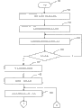
Fig. 4 A and 4B are the process flow diagrams that disposes the method for the programming device in the first broadcast router parts that are present in Fig. 2.
Embodiment
At first, describe the full redundancy linearity now in more detail and can expand broadcast router 100 with reference to Fig. 1.As present see, the full redundancy linearity can be expanded broadcast router 100 and comprise intercoupling and can expand several broadcast router parts of broadcast router 100 to form more complete works of redundant linearity.Each broadcast router parts is the separation router devices that comprise the first and second router matrixes, and the second router matrix is the redundancy of the first router matrix.Therefore, each broadcast router contains first and second routing engines, be respectively applied for one of first and second router matrixes, each routing engine receives identical input digit audio data stream at its input end, and places identical outputting digital audio data stream on its output terminal.Such just as disclosed here, being used to construct the full redundancy linearity, can to expand each broadcast router parts of broadcast router all be the broadcast router of N * M size.But, it is contemplated that fully the full redundancy linearity can be expanded broadcast router 100 and can replace with the broadcast router parts that differed from one another by size and constitute.
As further disclosed herein, the full redundancy linearity can be expanded broadcast router 100 and form by the first, second, third and the 4th broadcast router parts 102,104,106 and 108 are coupled.Certainly, current disclosed full redundancy linearity can be expanded broadcast router 100 and is made up of purely 4 broadcast router parts and gives an example.Therefore, should clearly realize that, can expand broadcast router 100 according to the full redundancy linearity of principles of construction of the present invention and can utilize the broadcast router parts of various other numbers to form.First, second, third with the 4th broadcast router parts 102,104,106 with 108 when all being connected in mode disclosed herein, collective (collectively) forms the full redundancy linearity can expand broadcast router 100, and can leave in together in as shown in Figure 1 the common chassis, perhaps if necessary, leave in the discrete frame.Though as mentioned previously, broadcast router parts 102,104,106 and 108 can have the size that differs from one another, and perhaps alternatively, can all have identical N * M size, and the verified size that is suitable for imagining use herein is 256 * 256.And the suitable configuration that the full redundancy linearity can be expanded broadcast router 100 each size that can be coupled is 5 broadcast router parts of 256 * 256, thereby causes producing 1,280 * 1,280 broadcast router.
The first broadcast router parts 102 are made up of the first router matrix 102A and second (or " redundancy ") the router matrix 102B that is used for this first router matrix of replacement 102A under the situation that the first router matrix 102A breaks down.Similarly, the full redundancy linearity can be expanded in second, third and the 4th broadcast router parts 104,106 and 108 of broadcast router 100 each respectively by the first router matrix 104A, 106A and 108A and be respectively applied for the second redundant router matrix 104B, the 106B and the 108B that replace described the first router matrix 104A, 106A and 108A under the situation that they break down and form.Certainly, specifying the second router matrix 102B, 104B, 106B and 108B is redundant matrix, so that using as backup when the first router matrix 102A, 104A, 106A and 108A break down is arbitrarily purely, and it is contemplated that fully being positioned at right any one of the router matrix of broadcast router parts can be as another backup of the router matrix centering that has those broadcast router parts.
As further seeing from Fig. 1, the first router matrix 106A of the first router matrix 102A of the first broadcast router parts 102, the first router matrix 104A of the second broadcast router parts 104, the 3rd broadcast router parts 106 and the first router matrix 108A of the 4th broadcast router parts 108 are coupled to defer to the complete first kind of configuration that is connected the router matrix of topological structure.Similarly, the second router matrix 108B of the second router matrix 106B of the second router matrix 104B of the second router matrix 102B of the first broadcast router parts 102, the second broadcast router parts 104, the 3rd broadcast router parts 106 and the 4th broadcast router parts 108 is coupled to defer to the complete second kind of configuration that is connected topological structure as first kind of configuration.Connect in the topological structure complete, each router matrix of router matrix configuration is by separating link and each other router matrix coupling that forms this kind router matrix configuration part.
Therefore, for first kind of configuration of router matrix, first, second is coupled with the first router matrix 104A of the second broadcast router parts 104, the first router matrix 106A of the 3rd broadcast router parts 106 and the first router matrix 108A of the 4th broadcast router parts 108 respectively with the 3rd two-way link 110,112 and the 114 the first router matrix 102A with the first broadcast router parts 102.In addition, the 4th and the 5th two-way link 116 and the 118 the first router matrix 104A with the second broadcast router parts 104 are coupled with the first router matrix 106A of the 3rd broadcast router parts 106 and the first router matrix 108A of the 4th broadcast router parts 108 respectively.At last, the 6th two-way link 120 is coupled the first router matrix 106A of the 3rd broadcast router parts 106 and the first router matrix 108A of the 4th broadcast router parts 108.
Similarly, for second kind of configuration of router matrix, first, second is coupled with the second router matrix 104B of the second broadcast router parts 104, the second router matrix 106B of the 3rd broadcast router parts 106 and the second router matrix 108B of the 4th broadcast router parts 108 respectively with the 3rd two-way link 122,124 and the 126 the second router matrix 102B with the first broadcast router parts 102.In addition, the 4th and the 5th two-way link 128 and the 130 the second router matrix 104B with the second broadcast router parts 104 are coupled with the second router matrix 106B of the 3rd broadcast router parts 106 and the second router matrix 108B of the 4th broadcast router parts 108 respectively.At last, the 6th two-way link 132 is coupled the second router matrix 106B of the 3rd broadcast router parts 106 and the second router matrix 108B of the 4th broadcast router parts 108.
Now broadcast router parts 102,104,106 and 108 will be described in further detail.Fig. 2 shows the first broadcast router parts 102.On the other hand, second, third disposes similarly with the 4th broadcast router parts 104,106 and the 108 and first broadcast router parts 102.Therefore, do not need to describe in further detail second, third and the 4th broadcast router parts 104,106 and 108.Should be noted that succinct for what describe, omitted in the following description derive from second, third and the 4th broadcast router parts 104,106 and 108, to the input of the first broadcast router parts 102.Discussed the further details of such input when being incorporated into this by reference in front in pending trial U.S. Patent application 10/__ (attorney docket IU020160) number.
See that as present the first broadcast router parts 102 comprise the first router matrix card 134A and the second router matrix card 134B that disposes equally with the first router matrix card 134A.In the frame (not shown) of broadcast router 100, hold slidably and among the first and second router matrix card 134A and the 134B each is installed supportably.Certainly, although when putting into practice disclosed herein certain aspect of the present invention, do not need to use a plurality of router matrix cards, but a plurality of router matrix cards of preferred usually use, because it helps the continuous proper operation of broadcast router 100 and the repairing and/or the replacement of the router matrix card that breaks down, and can not upset the router matrix card of operate as normal.
Hold slidably equally and what install supportably is that input card 136-1 is to 136-N and output card 138-1 to 138-N by frame.Each input card 136-1 is coupled to the first router matrix card 134A and the second router matrix card 134B to 136-N.Equally, each output card 138-1 to 138-N is coupled to the first router matrix card 134A and the second router matrix card 134B.Certainly, although the input and output card 136-1 that figure 2 illustrates separation is to 136-N and 138-1 to 138-N, but what should be understood that knows, if desired, being present in function on the input and output card of for example input card 136-N and output card 138-1 can replace with and place on the single I/O card.In addition, although Fig. 1 shows the input and output card 136-1 of separation to 136-N and 138-1 to 138-N, but it is contemplated that fully, depend on free space thereon, be illustrated as the output card of the input card that is present in input card 136-1 for example, for example output card 138-1 or all or part of function on the two can replace be present in the first router matrix card 134A, the second router matrix card 134B or they some in conjunction with last.
Being present in each input card 136-1 to the 136-N is that input signal is selected the circuit (not shown).This input signal selects circuit 123 to select to be sent to the input signal of the first router matrix card 122A and the second router matrix card 122B from a plurality of input signals that receive thus.As disclosed here, each from input card 136-1 to 136-N of each among the first and second router card 134A and the 134B receives in N the input digit audio data stream one.Certainly, such configuration is exemplary purely, it is contemplated that fully, receives a plurality of in N the input digit audio data stream in one can be from input card 136-1 to 136-N.In addition, each in N input digit audio data stream all is routed to each the first router card and the second router card in second, third and the 4th broadcast router parts 104,106 and 108.Similarly, each among the first and second router card 134A and the 134B respectively from second, third and the 4th broadcast router parts 104,106 and 108 receive input digit audio data stream N+1 to 2N, 2N+1 to 3N and 3N+1 to 4N.Like this, the first router matrix card 134A and the second router matrix card 134B receive 4N same input.
Be present in that function on each among the first and second router matrix card 134A and the 134B allows in its M the output each to be connected to arrive it 4N import in selected one.Control by the control circuit (not shown) and from 4N input, to select all coupled specific one of M each in exporting.Control first and second router matrix card 134A and the 134B in the same manner, thereby M the outputting digital audio data stream of the first router matrix card 134A is identical with M the outputting digital audio data stream of the second router matrix card 134B.In M outputting digital audio data stream each propagates into output card 138-1 in the 138-M corresponding from the first and second router matrix card 134A and 134B.Being present in each output card 138-1 to the 138-M is output signal selection circuit (not shown), and this output signal selection circuit is from first outputting digital audio data stream that receives from the first router matrix card 134A and the digital audio data stream of selecting to output to the first broadcast router parts 102 from the second outputting digital audio data stream that the second router matrix card 134B receives.
Will describe as following more comprehensively, input card 136-1 in the 136-N each, each in the 138-M of the first router matrix card 134A, the second router matrix card 134B and output card 138-1 comprises the programming device of one or more for example FPGA, whenever broadcast router 100 is powered up, or when the card heat that has programming device is thereon inserted the I/O bus of broadcast router 100, require the described programming device of configuration.Be coupled to input card 136-1 in the 136-N each, the configuration control card 140 of each in the 138-M of the first router matrix card 134A, the second router matrix card 134B and output card 138-1 offers existence FPGA or other programming devices thereon with configuration information.Similar to 138-M with input card 136-1 to 136-N, the first router matrix card 134A, the second router matrix card 134B and output card 138-1, configuration control card 140 is slidably received within the frame of the first broadcast router parts 102, and is installed supportably by this frame.
Certainly, FPGA only is a programming device one type, need configuration information when powering up, it is contemplated that fully, input card 136-1 in the 136-N one or more, the first router matrix card 134A, the second router matrix card 134B and output card 138-1 one or more in the 138-M in can have the programming device that needs configuration information of other types, to replace FPGA or to exist jointly with FPGA.Similarly, although Fig. 2 shows three kinds and is coupled to configuration control card 140 so that receive card---input card, router matrix card and the output card of configuration information from this configuration control card, but it is contemplated that fully, exist the various cards of one or more FPGA or other programming devices can be coupled to configuration control card 140 thereon to receive information able to programme.In addition, although Fig. 2 is illustrated as the card of illustrational all kinds and is connected to configuration control card 140, so that receive configuration information from this configuration control card, but it is contemplated that, the card of one or more illustrational kinds can not need configuration information, or alternatively, can not be coupled to configuration control card 140 to receive configuration information.At last, although Fig. 2 shows personality card---specifically, configuration control card 140---dispose and be present in input card 136-1 to 136-N, the first router matrix card 134A, the second router matrix card 134B, with the programming device of output card 138-1 to the 138-M, but should clearly understand with locating, configuration is present in input card 136-1 to 136-N, the first router matrix card 134A, the second router matrix card 134B, can replace with to the required function of the programming device on the 138-M with output card 138-1 and to be present on the multifunction card, for example replace broadcast router parts 102 to carry out the card of other control function.
Referring to Fig. 3, will describe configuration control card 140 and output card 138-1 in detail to interconnecting between the 138-M.Although in Fig. 3, can see configuration control card 140 and output card 138-1 optional feature to 138-M, but it should be clearly know that, Fig. 3 has greatly been simplified, and for easy description, omitted configuration control card 140 and output card 138-1 to 138-M, understand the present invention unwanted various parts.Should also be appreciated that, although be not illustrated in Fig. 3, input card 136-1 in the 136-N each, the first router matrix card 134A and the second router matrix card 134B:(1) exist thereon and be present in output card 138-1 to the identical optional feature of the parts on the 138-M; (2) interconnect with configuration control card 140 all similarly; (3) all configurations in an identical manner.
See as present, be present in the peripheral controllers 144-1 that to be FPGA142-1 be coupled to 142-M to 142-M and with FPGA 142-1 on output card 138-1 each in the 138-M to 144-M.On the other hand, being present in configuration on the control card 140 is storer 146 and the master controller 148 that is coupled to storer 146, and described storer 146 usefulness act on the shared storage vault of the configuration information of FPGA 142-1 each in the 142-M.At last, master controller 148 is coupled to peripheral controllers 144-1 each in the 144-M.Will describe more all sidedly as following, the link of above-mentioned FPGA142-1 to 142-M, peripheral controllers 144-1 to 144-M, between master controller 148 and the storer 146 is used to make it possible in response to flowing to the signal of storer 146 from FPGA 142-1 to 142-M, and makes control information flow to FPGA 142-1 to 142-M from storer 146.But, although should be noted that peripheral controllers 144-1 that Fig. 3 shows a series of separation to 144-M, each is corresponding to FPGA 142-1 in the 142-M, but it is contemplated that fully, be present in function in each peripheral controllers and can replace with and place corresponding FPGA.Certainly, in such structure, FPGA 142-1 each in the 142-M will be directly coupled to master controller 148.In addition, FPGA142-1 is described below execution those functions of carrying out to 144-M into by peripheral controllers 144-1 to 142-M.
Below with reference to Fig. 4, describe in detail now to utilize and share the configuration information storage vault, specifically, be kept at the configuration information in the storer 146, dispose the FPGA 142-1 that for example is present on a plurality of cards (herein for output card 138-1 to 138-M) method to a plurality of configurable devices of 142-M.But, further openly should be noted that the present invention can be used for various configuring technicals before the foregoing.A kind of such technology relates to the configuration of a plurality of devices of common type of device.In this art, will in storer 146, preserve single configuration file, for example FPGA configuration file 149-1.Think that this technology can be used for disposing the situation advantageous particularly of a plurality of programming devices at single configuration file.Another kind of technology relates to the configuration of a plurality of programming devices of different components type.In this art, must in storer 146, preserve a plurality of configuration files, for example first, second and the 3rd configuration file 149-1,149-2 and 149-3.
Further describe these technology before, with the further explanation that provides with phrase " dissimilar programming devices " terms relevant, current use " dissimilar ".More specifically, except the common understanding to its usage, as used herein, the programming device of phrase " dissimilar " meaning is the programming device that comprises same physical type, if such device needs different configuration informations.For example, the FPGA that configuration is present on the input card may need first group of instruction, and the FPGA that configuration is present on the router card may need to be different from first group of second group of instruction of instructing.If like this, think that the FPGA that is present on the input card is dissimilar programming devices with respect to the FPGA that is present on the router card.On the contrary, think and to use same group to instruct any two programming devices that programming device is a same type that dispose no matter whether they are physically identical.
The method of a plurality of programming devices of a plurality of same types of configuration is described now with reference to Fig. 4.This method starts from step 150, in step 152, for example the programming device of FPGA 142-1 sends configuring request to the peripheral controllers that is present in the configurable device of asking on the common plate, and this peripheral controllers is to be present in peripheral controllers 144-1 on the output card 138-1 with FPGA 142-1 herein.Sending configuring request can be triggered by a plurality of incidents.For example, the slot (not shown) of I/O (or " I/O ") bus by output card 138-1 being inserted the first broadcast router parts 102 or FPGA 142-1 is powered up by the first broadcast router parts 102 are powered up self will make FPGA 142-1 send configuring request.Then the peripheral controllers (herein being peripheral controllers 144-1) that receives configuring request is forwarded to master controller 148 with this request, and master controller receives configuring request in step 154.Certainly, replace with and be present among the FPGA 142-1 if be present in function among the peripheral controllers 144-1, then FPGA142-1 directly is dealt into master controller 148 with above-mentioned configuring request.
When master controller 148 when step 154 detects the arrival of configuring request, this method proceeds to step 156, in this step, master controller 148 will be waited for the arrival of additional configurations request in the previously selected time limit.For example, if send detected configuring request by the first broadcast router parts 102 are powered up to trigger, it is contemplated that, for the card of output card 138-1 similar configuration on the configuring request of the FPGA that exists will very fast arrival after sending detected configuring request by FPGA 142-1.Proceed to step 158, if the time limit previously selected, that master controller will be waited for another configuring request during this period not expiration as yet, then this method turns back to step 156, to wait for another configuring request.But if expire in definite previously selected time limit of step 158, then described method proceeds to step 160, in this step, and the programming device of master controller 148 beginning configuring request configurations.
Because as long as one type device of configuration, described method proceeds to step 164 from step 160, in this step, master controller 148 begins to check the programming device that is coupled with it, with the configuration of having discerned which programming device request.For this reason, in step 164, master controller 148 is selected first programming device from a plurality of programming devices that are coupled with it.For example, master controller 148 can be selected FPGA142-1.Certainly, are same types owing to be coupled to all programmable device of master controller 148, master controller 148 does not need to consider the type of selected programming device.Subsequently, described method proceeds to step 166, in this step, the peripheral controllers (being peripheral controllers 144-1 herein) of selected programming device (being FPGA 142-1 herein) is coupled in master controller 148 inquiries, whether has asked configuration to determine selected programming device.In step 166, if master controller 148 determines that the peripheral controllers of being inquired has sent configuring request for selected programming device, then described method proceeds to step 168, in this step, and the selected programming device of master controller 148 configurations.For this reason, master controller 148 retrieval is kept at the configuration information among the first area 149-1 of storer 146, and the configuration information of retrieval is transferred to peripheral controllers 144-1.Peripheral controllers 144-1 utilizes the configuration information that receives to handle the configuration of FPGA 142-1 in a conventional manner subsequently.Certainly, replace with and be present among the FPGA 142-1 if be present in function among the peripheral controllers 144-1, then master controller is with direct access inquiry FPGA142-1, to determine whether FPGA 142-1 has asked configuration.If asked configuration, the configuration that master controller 148 will be retrieved subsequently is transferred to FPGA 142-1.
When the configuration of having finished FPGA 142-1 in step 168, perhaps when when step 166 determines that FPGA142-1 never sends configuring request, described method proceeds to step 170.In step 170, determine whether to exist other whether to have sent configuring request and the programming device checked with regard to them.If there is other programming device that need check, described method proceeds to step 172, in this step, selects next programming device.Described method turns back to step 166 subsequently, so that be further processed with aforesaid method.But, if in step 172, determine poll described programming device whether sent configuring request so that determine them, then described method will proceed to the step 178 of its termination.
Return Fig. 4 once more, share describe in detail to utilize again with the configuration information storage vault disposes a plurality of programming devices in having the system of a plurality of cards method, wherein on described a plurality of cards, have polytype programming device.As previously mentioned, this method starts from step 150, in step 152, still for example the programming device of FPGA142-1 sends configuring request to the peripheral controllers that is present in the configurable device of asking on the common plate, and this peripheral controllers still is present in peripheral controllers 144-1 on the output card 138-1 with FPGA 142-1 herein.Then the peripheral controllers (herein being peripheral controllers 144-1) that receives configuring request is transferred to master controller 148 with this request, and master controller receives configuring request in step 154.Certainly, replace with and be present among the FPGA142-1 if be present in function among the peripheral controllers 144-1, then FPGA 142-1 directly is dealt into master controller 148 with above-mentioned configuring request.
When master controller 148 when step 154 detects the arrival of configuring request, this method proceeds to step 156, in this step, master controller 148 will be waited for the arrival of additional configurations request in the previously selected time limit.Proceed to step 158, if master controller will be waited for the not expiration as yet of previously selected time limit of additional configurations request during this period, then this method turns back to step 156, to wait for the additional configurations request.But if expire in definite previously selected time limit of step 158, then described method proceeds to step 160, in this step, and the programming device of master controller 148 beginning configuring request configurations.
Because in this embodiment of the invention, the programming device of polytype request configuration can be arranged, in step 162, master controller 148 selects the programming device of the first kind to dispose.Expection can use various technology to determine the particular type of selected device in step 162.For example, the type of device that detects its initial configuration request in step 154 can be the type of device of selecting in step 162.According to this technology, when receiving the additional configurations request, master controller 148 will check about type of device and receive each configuring request, and be kept at the tabulation of all types of devices that receives before the previously selected time limit expiration about its at least one configuring request.Proceed to step 164, master controller 148 begins to check programming device, looks at whether they have asked configuration.In addition, master controller 148 is checked programming device so that determine that the processing whether they have asked to dispose can easily be changed.For example, each peripheral controllers that master controller 148 can poll be associated with programming device, to determine: whether the programming device that (1) is relevant is selected type of device; (2) on behalf of programming device, whether peripheral controllers sent configuring request.Certainly, replace with and be present in the corresponding programming device if be present in function in the peripheral controllers, then master controller is with each peripheral controllers of direct poll, and to determine: whether (1) programming device is selected type of device; (2) whether programming device has sent configuring request.Master controller is with direct access inquiry FPGA 142-1, to determine whether FPGA142-1 has asked configuration.
In step 166, if master controller 148 determines that the peripheral controllers of being inquired has sent configuring request for selected programming device, and selected programming device is the type of described selection, then described method proceeds to step 168, in this step, the selected programming device of master controller 148 configurations.For this reason, master controller is retrieved the configuration information of preserving in the zone of configuration information storer 146, that preserve the programming device type of asking, and the configuration information of retrieval is transferred to peripheral controllers 144-1.Peripheral controllers 144-1 utilizes the configuration information that receives to handle the configuration of FPGA 142-1 in a conventional manner subsequently.Certainly, if being present in function in the peripheral controllers replaces with and is present in the selected programming device, then in step 166, whether master controller 148 replaces with determines whether selected programming device has sent configuring request and is selected type, in step 168, master controller 148 is transferred to FPGA 142-1 with the configuration information of retrieval.
When the configuration of having finished FPGA 142-1 in step 168, perhaps when when step 166 determines that FPGA142-1 never sends configuring request, described method proceeds to step 170.Whether in step 170, determining whether to exist other whether to have sent configuring request and they with regard to them is selected programming device type and the programming device checked.If there is other programming device that need check, described method proceeds to step 172, in this step, selects next programming device.Described method turns back to step 166 subsequently, so that be further processed with aforesaid method.But, if in step 172, determine poll described programming device so that determine whether they have sent configuring request and whether they are selected programming device types, then described method will proceed to step 174, in this step, master controller 148 determines whether to exist has asked programming device configuration, other type.For example, master controller 148 can be checked the tabulation of the programming device type of request configuration, looks at whether to exist programming device that be not configured as yet, other type.If there is the programming device of other type that needs configuration, then described method proceeds to step 176, and in this step, master controller 148 is selected the programming device of next type, to be configured.Described method turns back to step 164 subsequently, so that be further processed with aforesaid method.But if determine to be configured programming device all types of, the request configuration in step 174, then described method will finish in step 178.
Certainly, there is the multiple method of putting into practice the embodiment of the invention, wherein use shared configuration information storage vault to dispose polytype programming device, it does not need main control 148 to preserve the tabulation of the programming device type of request configuration, perhaps for each programming device type poll of having asked configuration each programming device once.Like this, after beginning to dispose the programming device of asking, master controller 148 will be inquired selected peripheral controllers, and whether programming device associated therewith has asked configuration.Asked configuration if peripheral controllers is pointed out programming device, then master controller 148 type of putting up with the programming device that is associated with peripheral controllers is inquired.Master controller 148 can use this information from the suitable configuration information of storer 146 retrievals, and proceeds the configuration of aforesaid programming device.Master controller 148 will be selected next programming device subsequently, and repeat this processing and cross all programming devices determining whether they have asked configuration up to poll, and if asked configuration, whether obtained configuration.Should be appreciated that said method has reduced in order to dispose the number that all programming device main controls 148 of asking must be transmitted.Said method has also been eliminated any needs of the tabulation of the programming device type that 148 requests of preserving are disposed for master controller.
Therefore, open here and illustrate the broadcast router with the shared configuration information storage vault that is used to dispose a plurality of programming devices, each in described a plurality of programming devices is positioned on the different plate of broadcast router.Share the configuration information storage vault and can be used for disposing wherein a plurality of programming devices on each different plate that are positioned at the same plate type, perhaps can be used for disposing wherein a plurality of programming devices on each different plate that are positioned at different board types.By configuration broadcast router by this way, by eliminating the sizable saving that has realized memory resource for the needs of the split memory spare that is used for each programming device.
Certainly, though shown and described the preferred embodiments of the present invention herein, those of ordinary skill in the art can make various modifications and other change under the situation that does not depart from spirit of the present invention or principle.Therefore, protection scope of the present invention is not limited to embodiment described herein, but is only limited by appended claims.
Claims (20)
1. an electronic system (100) comprising:
A plurality of function cards (138-1 is to 138-M), each function card have at least one existence programming device (142-1 is to 142-M) thereon;
Be coupled to each the configuration control card (140) in described a plurality of function card (138-1 is to 138-M); Wherein said configuration control card (140) disposes described at least one programming device (142-1 is to 142-M) on each that is present in described a plurality of function card (138-1 is to 138-M); With
Be present in the peripheral controllers (144-1 is to 144-M) on each in described a plurality of function card (138-1 is to 138-M);
In the described peripheral controllers (144-1 is to 144-M) each is handled:
(1) will derive from the request that is present in the described programming device (142-1 is to 142-M) in described a plurality of function card (138-1 is to 138-M) one with described peripheral controllers (144-1 is to 144-M) and be transferred to described configuration control card (140) for configuration; With
(2) will be transferred to by the configuration information that described configuration control card (140) provides with described peripheral controllers (144-1 is to 144-M) and be present in described programming device (142-1 is to 142-M) in described a plurality of function card (138-1 is to 138-M) one.
2. electronic system as claimed in claim 1 also comprises:
Be present in the memory sub-system (146) on the described configuration control card (140);
Wherein said configuration control card (140) utilization stored configuration information in described memory sub-system (146) disposes described at least one programming device (142-1 is to 142-M) on each that is present in described a plurality of function card (138-1 is to 138-M).
3. electronic system as claimed in claim 2, wherein said configuration control card (140) also comprises:
Master controller (148), it is coupled to described memory sub-system (146) and described a plurality of function card (138-1 is to 138-M);
The described configuration information of described master controller (148) utilization storage in described memory sub-system (146) disposes each in described a plurality of function card (138-1 is to 138-M).
4. electronic system as claimed in claim 3, each that wherein is present in described at least one programming device (142-1 is to 142-M) on each in described a plurality of function card (138-1 is to 138-M) is an on-site programmable gate array FPGA.
5. electronic system as claimed in claim 3, wherein:
In the described peripheral controllers (144-1 is to 144-M) each is handled: (1) will derive from the request for configuration that is present in the described programming device (142-1 is to 142-M) in described a plurality of function card (138-1 is to 138-M) one with described peripheral controllers (144-1 is to 144-M) and be transferred to described master controller (148); (2) will be transferred to by the configuration information that described master controller (148) provide with described peripheral controllers (144-1 is to 144-M) and be present in described programming device (142-1 is to 142-M) in described a plurality of function card (138-1 is to 138-M) one.
6. electronic system as claimed in claim 2, wherein said a plurality of function cards (138-1 is to 138-M) also comprise:
The function card of a plurality of first kind (136-1 is to 136-N), first group of instruction that the function card of the described first kind (136-1 is to 136-N) request is used to dispose it;
The function card of a plurality of second types (138-1 is to 138-M), second group of instruction that the function card of described second type (138-1 is to 138-M) request is used to dispose it;
Described first group of instruction storage is in the first area of described memory sub-system (146) (149-1), and described second group of instruction storage is in the second area (149-2) of described memory sub-system (146);
Wherein said configuration control card (140) utilizes described first group in the described first area (149-1) be stored in described memory sub-system (146) to instruct described second group in the second area (149-2) that the function card (136-1 is to 136-N) that disposes described a plurality of first kind, described configuration control card (140) utilization be stored in described memory sub-system (146) to instruct the function card (138-1 is to 138-M) that disposes described a plurality of second types.
7. electronic system as claimed in claim 6, wherein said configuration control card (140) also comprises:
Master controller (148) is coupled to the function card (136-1 is to 136-N) of described memory sub-system (146), described a plurality of first kind and the function card (138-1 is to 138-M) of described a plurality of second types;
Described master controller (148) utilizes described first group of each of instructing in the function card (136-1 is to 136-N) that disposes described a plurality of first kind of storing in the described first area of described memory sub-system (146) (149-1); With
Described configuration control card (140) utilizes described second group of each of instructing in the function card (138-1 is to 138-M) that disposes described a plurality of second types of storing in the described second area (149-2) of described memory sub-system (146).
8. electronic system as claimed in claim 7 also comprises:
In the described peripheral controllers (144-1 is to 144-M) each is handled: will derive from the request for the described function card of the described first kind of configuration that is present in described programming device (142-1 is to 142-M) in described a plurality of function card (136-1 is to 136-N, and 138-1 is to 138-M) one with described peripheral controllers (144-1 is to 144-M) and be transferred to described master controller (148); With
In the described peripheral controllers (144-1 is to 144-M) each is also handled: will be transferred to by the configuration information that described master controller (148) provide with described peripheral controllers (144-1 is to 144-M) and be present in described programming device (142-1 is to 142-M) in described a plurality of function card (136-1 to 136,138-1 is to 138-M) one.
9. a broadcast router (100) comprising:
The first router card (134A) has input end, output terminal and at least one existence programming device (142-1 is to 142-M) thereon;
A plurality of input cards (136-1 is to 136-N), each in described a plurality of input cards (136-1 is to 136-N) is coupled to the described input end of described router card (134A), and has at least one existence programming device (142-1 is to 142-M) thereon;
A plurality of output cards (138-1 is to 138-M), each in described a plurality of output cards (138-1 is to 138-M) is coupled to the described output terminal of described router card (134A), and has at least one existence programming device (142-1 is to 142-M) thereon; With
Configuration control card (140), it is coupled in each and the described a plurality of output cards (138-1 is to 138-M) in described router card (134A), the described a plurality of input cards (136-1 is to 136-N) each, described configuration control card (140) configuration be present in described at least one programming device (142-1 is to 142-M) on the described router card (134A), in described a plurality of input cards (136-1 is to 136-N) each with described a plurality of output cards (138-1 is to 138-M) in each.
10. broadcast router as claimed in claim 9 also comprises:
The second router card (134B) has input end, output terminal and at least one existence programming device (142-1 is to 142-M) thereon;
In described a plurality of input card (136-1 is to 136-N) each also is coupled to the described input end of described the second router card (134B); In described a plurality of output card (138-1 is to 138-M) each also is coupled to the described output terminal of described the second router card (134B);
Described configuration control card also disposes described at least one programming device (142-1 is to 142-M) that is present on the described the second router card (134B).
11. broadcast router as claimed in claim 9 also comprises:
Be present in the memory sub-system (146) on the described configuration control card (140), described memory sub-system (146) comprises first area (149-1), second area (149-2) and the 3rd zone (149-3);
Wherein said configuration control card (140) utilizes the configuration information be stored in the described first area (149-1) to dispose described at least one programming device (142-1 is to 142-M) on each that is present in described a plurality of input card (136-1 is to 136-N); The configuration information that utilization is stored in the described second area (149-2) disposes described at least one programming device (142-1 is to 142-M) that is present on the described the first router card (134A), utilizes the configuration information be stored in described the 3rd zone (149-3) to dispose described at least one programming device (142-1 is to 142-M) on each that is present in described a plurality of output card (138-1 is to 138-M).
12. broadcast router as claimed in claim 11 wherein is present on each in described a plurality of input card (136-1 is to 136-N), described the first router card (134A) is gone up, in the described programming device (142-1 is to 142-M) in described a plurality of output cards (138-1 is to 138-M) each each is an on-site programmable gate array FPGA.
13. broadcast router as claimed in claim 12, wherein said configuration control card (140) also comprises:
Master controller (148), be coupled in described memory sub-system (146), the described a plurality of input cards (136-1 is to 136-N) each, described the first router card (134A) and described a plurality of output card (138-1 is to 138-M);
Described master controller (148) utilizes first group of instruction of storing in the described first area of described memory sub-system (146) (149-1) to dispose each described at least one FPGA (142-1 is to 142-M) in described a plurality of input card (136-1 is to 136-N); Second group of instruction that utilization is stored in the described second area (149-2) of described memory sub-system (146) disposed described at least one FPGA (142-1 is to 142-M) of described the first router card (134A) and utilized the 3rd group of instruction of storing in described the 3rd zone (149-3) of described memory sub-system (146) to dispose each described at least one FPGA (142-1 is to 142-M) in described a plurality of output card (138-1 is to 138-M).
14. broadcast router as claimed in claim 13 also comprises:
The second router card (134B) has input end, output terminal and at least one existence FPGA (142-1 is to 142-M) thereon;
In described a plurality of input card (136-1 is to 136-N) each also is coupled to the described input end of described the second router card (134B);
In described a plurality of output card (138-1 is to 138-M) each also is coupled to the described output terminal of described the second router card (134B);
Described master controller (148) utilizes described second group of storing in the described second area (149-2) of described memory sub-system (146) to instruct described at least one FPGA (142-1 is to 142-M) that disposes described the second router card (134B).
15. broadcast router as claimed in claim 14 also comprises:
Be present on each in described a plurality of input card (136-1 is to 136-N), described first and second router cards (134A and 134B) are gone up and described a plurality of output router cards (138-1 is to 138-M) in each on peripheral controllers (144-1 is to 144-M);
In the described peripheral controllers (144-1 is to 144-M) each is handled: will derive from described peripheral controllers (144-1 is to 144-M) be present in described a plurality of input card (136-1 is to 136-N) one go up, described the first router card (134A) is gone up, described the second router card (134B) is gone up or described a plurality of output card (138-1 is to 138-M) in one on the request of described FPGA (142-1 is to 142-N) for disposing be transferred to described master controller (148); With
In the described peripheral controllers (144-1 is to 144-M) each is also handled: will be transferred to by the configuration information that described master controller (148) provide with described peripheral controllers (144-1 is to 144-M) be present in described a plurality of input card (136-1 is to 136-N) one go up, described the first router card (134A) is gone up, described the second router card (134B) is gone up or described a plurality of output card (138-1 is to 138-M) in one on described FPGA (142-1 is to 142-N).
16. method that is used for configuration broadcast router (100), described broadcast router (100) has at least one card that has one or more configurable devices (142-1 is to 142-M) thereon, and (134A is to 134B, 136-1 is to 136-N, and 138-1 is to 138-M), described method comprises:
Send first configuring request, described first configuring request is sent by the first configurable device (142-1 is to 142-M) on first card that is present in described at least one card (134A is to 134B, and 136-1 is to 136-N, and 138-1 is to 138-M);
From sharing configuration storage vault (146) retrieval of configuration information; With
The described configuration information that utilization retrieves from described shared configuration storage vault (146) disposes described configurable device (142-1 is to 142-M) of asking.
17. method as claimed in claim 16 also comprises;
(134A is to 134B when described broadcast router (100) has two or more cards that have one or more configurable devices (142-1 is to 142-M) thereon, 136-1 is to 136-N, 138-1 is to 138-M) time, send second configuring request, (134A is to 134B by being present in described at least one card for described second configuring request, 136-1 is to 136-N, and 138-1 is to 138-M) in second card on the second configurable device (142-1 is to 142-M) send;
Retrieve described configuration information from described shared configuration storage vault (146); With
The described configuration information that utilization retrieves from described shared configuration storage vault (146) disposes the described second configurable device (142-1 is to 142-M) of asking;
Wherein use identical configuration information to dispose the described first and second configurable devices (142-1 is to 142-M) of asking.
18. method as claimed in claim 16, wherein said broadcast router (100) comprises the card (136-1 is to 136-N) of at least one first kind and the card (138-1 is to 138-M) of at least one second type, (136-1 is to 136-N for the card of described at least one first and second type, 138-1 is to 138-M) in each have at least one and have thereon configurable device (142-1 is to 142-M), described method also comprises:
First group of instruction of storage in the first area of described shared configuration storage vault (146) (149-1);
Second group of instruction of storage in the second area (149-2) of described shared configuration storage vault (146);
If described configurable device (142-1 is to 142-M) of asking is present on the card (136-1 is to 136-N) of described at least one first kind, then retrieve described first group of instruction;
If described configurable device (142-1 is to 142-M) of asking is present on the card (138-1 is to 138-M) of described at least one second type, then retrieve described second group of instruction; If described configurable device (142-1 is to 142-M) of asking is present on the card (136-1 is to 136-N) of described at least one first kind, then utilize from the described first area (149-1) of described shared configuration storage vault (146) described first group of retrieval to instruct and dispose described configurable device (142-1 is to 142-M) of asking; If described configurable device (142-1 is to 142-M) of asking is present on the card (138-1 is to 138-M) of described at least one second type, then utilize from the second area (149-2) of described shared configuration storage vault (146) described second group of retrieval to instruct and dispose described configurable device (142-1 is to 142-M) of asking.
19. method as claimed in claim 16, wherein said broadcast router (100) also comprise the configuration control card (140) that has master controller (148) and described shared configuration storage vault (146) thereon, described method further comprises:
(134A is to 134B by being present in described at least one card in described master controller (148) detection, 136-1 is to 136-N, and 138-1 is to 138-M) in described first card on described one or more configurable devices (142-1 is to 142-M) in first configuring request sent of the described first configurable device;
The time limit of described master controller after first configuring request of described detection begins placement algorithm when expiring, the described time limit allows the another one in described one or more configurable devices (142-1 is to 142-M) to ask configuration before described placement algorithm begins, and realizes the configurable device of described another one when having a more than configurable device.
20. method as claimed in claim 19, wherein said placement algorithm also comprises:
Selection is present in described at least one card (134A is to 134B, and 136-1 is to 136-N, and 138-1 is to 138-M) of described broadcast router (100) the first configurable device on the card;
Inquire whether selected configurable device wishes to be configured;
If selected configurable device indicates its hope to be configured, then configuration information is propagated into selected configurable device;
Selection is present in described at least one card (134A is to 134B, and 136-1 is to 136-N, and 138-1 is to 138-M) of described broadcast router (100) the next configurable device on the card; With
Repeat described inquiry, propagation and selection step, up to having inquired all described one or more configurable devices (142-1 is to 142-M).
Applications Claiming Priority (4)
| Application Number | Priority Date | Filing Date | Title |
|---|---|---|---|
| US39034702P | 2002-06-21 | 2002-06-21 | |
| US60/390,347 | 2002-06-21 | ||
| US60/390347 | 2002-06-21 | ||
| PCT/US2003/019015 WO2004002055A1 (en) | 2002-06-21 | 2003-06-13 | Broadcast router having a shared configuration repository |
Publications (2)
| Publication Number | Publication Date |
|---|---|
| CN1663170A CN1663170A (en) | 2005-08-31 |
| CN1663170B true CN1663170B (en) | 2010-05-26 |
Family
ID=30000543
Family Applications (1)
| Application Number | Title | Priority Date | Filing Date |
|---|---|---|---|
| CN03814569.3A Expired - Fee Related CN1663170B (en) | 2002-06-21 | 2003-06-13 | Broadcast router having a shared configuration repository |
Country Status (7)
| Country | Link |
|---|---|
| US (1) | US7805766B2 (en) |
| EP (1) | EP1522164B1 (en) |
| JP (2) | JP4848130B2 (en) |
| CN (1) | CN1663170B (en) |
| AU (1) | AU2003245533A1 (en) |
| MX (1) | MXPA04012761A (en) |
| WO (1) | WO2004002055A1 (en) |
Families Citing this family (17)
| Publication number | Priority date | Publication date | Assignee | Title |
|---|---|---|---|---|
| JP4388470B2 (en) | 2002-06-21 | 2009-12-24 | トムソン ライセンシング | Fault-tolerant broadcast router |
| US7313384B1 (en) | 2002-10-31 | 2007-12-25 | Aol Llc, A Delaware Limited Liability Company | Configuring wireless devices |
| US7752329B1 (en) | 2002-10-31 | 2010-07-06 | Aol Inc. | Migrating configuration information based on user identity information |
| JP4914212B2 (en) * | 2003-08-15 | 2012-04-11 | ジーブイビービー ホールディングス エス.エイ.アール.エル. | Broadcast router with changeable functionality |
| JP4855864B2 (en) * | 2006-08-11 | 2012-01-18 | 富士通セミコンダクター株式会社 | Direct memory access controller |
| US20090060043A1 (en) * | 2007-08-29 | 2009-03-05 | Geert Nuyttens | Multiviewer based on merging of output streams of spatio scalable codecs in a compressed domain |
| JP5879246B2 (en) * | 2011-12-19 | 2016-03-08 | アラクサラネットワークス株式会社 | Network relay device |
| DE102012205160A1 (en) * | 2012-03-29 | 2013-10-02 | Robert Bosch Gmbh | Communication arrangement and method for configuring programmable hardware |
| US9049173B2 (en) | 2013-06-05 | 2015-06-02 | Fortinet, Inc. | Cloud based logging service |
| US9223715B2 (en) | 2013-08-21 | 2015-12-29 | Via Alliance Semiconductor Co., Ltd. | Microprocessor mechanism for decompression of cache correction data |
| US9348690B2 (en) * | 2013-08-21 | 2016-05-24 | Via Alliance Semiconductor Co., Ltd. | Correctable configuration data compression and decompression system |
| US8982655B1 (en) | 2013-08-21 | 2015-03-17 | Via Technologies, Inc. | Apparatus and method for compression and decompression of microprocessor configuration data |
| US9606933B2 (en) | 2014-05-22 | 2017-03-28 | Via Alliance Semiconductor Co., Ltd. | Multi-core apparatus and method for restoring data arrays following a power gating event |
| US9665490B2 (en) | 2014-05-22 | 2017-05-30 | Via Alliance Semiconductor Co., Ltd. | Apparatus and method for repairing cache arrays in a multi-core microprocessor |
| US9395802B2 (en) | 2014-05-22 | 2016-07-19 | Via Alliance Semiconductor Co., Ltd. | Multi-core data array power gating restoral mechanism |
| US10963001B1 (en) | 2017-04-18 | 2021-03-30 | Amazon Technologies, Inc. | Client configurable hardware logic and corresponding hardware clock metadata |
| US10922071B2 (en) * | 2019-03-13 | 2021-02-16 | Quanta Computer Inc. | Centralized off-board flash memory for server devices |
Citations (6)
| Publication number | Priority date | Publication date | Assignee | Title |
|---|---|---|---|---|
| US5465106A (en) * | 1992-09-25 | 1995-11-07 | Hughes Aircraft Company | Generic driver interface card |
| US5537607A (en) * | 1993-04-28 | 1996-07-16 | International Business Machines Corporation | Field programmable general purpose interface adapter for connecting peripheral devices within a computer system |
| US5550984A (en) * | 1994-12-07 | 1996-08-27 | Matsushita Electric Corporation Of America | Security system for preventing unauthorized communications between networks by translating communications received in ip protocol to non-ip protocol to remove address and routing services information |
| US5628028A (en) * | 1995-03-02 | 1997-05-06 | Data Translation, Inc. | Reprogrammable PCMCIA card and method and apparatus employing same |
| US5659684A (en) * | 1995-02-03 | 1997-08-19 | Isdn Systems Corporation | Methods and apparatus for interconnecting personal computers (PCs) and local area networks (LANs) using packet protocols transmitted over a digital data service (DDS) |
| US5819050A (en) * | 1996-02-29 | 1998-10-06 | The Foxboro Company | Automatically configurable multi-purpose distributed control processor card for an industrial control system |
Family Cites Families (16)
| Publication number | Priority date | Publication date | Assignee | Title |
|---|---|---|---|---|
| WO1992022955A1 (en) * | 1991-06-19 | 1992-12-23 | Ant Nachrichtentechnik Gmbh | Switching regulator |
| JP3239129B2 (en) * | 1991-09-18 | 2001-12-17 | 株式会社日立製作所 | Routing control method |
| US5784291A (en) * | 1994-12-22 | 1998-07-21 | Texas Instruments, Incorporated | CPU, memory controller, bus bridge integrated circuits, layout structures, system and methods |
| US5727221A (en) * | 1994-12-22 | 1998-03-10 | Texas Instruments Incorporated | Computer system power management interconnection circuitry and systems |
| US5852370A (en) * | 1994-12-22 | 1998-12-22 | Texas Instruments Incorporated | Integrated circuits for low power dissipation in signaling between different-voltage on chip regions |
| US5943507A (en) * | 1994-12-22 | 1999-08-24 | Texas Instruments Incorporated | Interrupt routing circuits, systems and methods |
| JPH08316329A (en) * | 1995-05-24 | 1996-11-29 | Nec Eng Ltd | Information processor |
| US6093213A (en) * | 1995-10-06 | 2000-07-25 | Advanced Micro Devices, Inc. | Flexible implementation of a system management mode (SMM) in a processor |
| US5717691A (en) * | 1995-10-30 | 1998-02-10 | Nec Usa, Inc. | Multimedia network interface for asynchronous transfer mode communication system |
| US6185641B1 (en) * | 1997-05-01 | 2001-02-06 | Standard Microsystems Corp. | Dynamically allocating space in RAM shared between multiple USB endpoints and USB host |
| KR100231286B1 (en) | 1997-06-28 | 1999-11-15 | 김영환 | The packet router |
| US6088785A (en) * | 1998-04-15 | 2000-07-11 | Diamond Multimedia Systems, Inc. | Method of configuring a functionally redefinable signal processing system |
| KR20010056663A (en) | 1999-12-16 | 2001-07-04 | 박종섭 | HDLC communication apparatus in base station of communication system using packet router |
| GB2373595B (en) * | 2001-03-15 | 2005-09-07 | Italtel Spa | A system of distributed microprocessor interfaces toward macro-cell based designs implemented as ASIC or FPGA bread boarding and relative common bus protocol |
| US6535924B1 (en) * | 2001-09-05 | 2003-03-18 | Pluris, Inc. | Method and apparatus for performing a software upgrade of a router while the router is online |
| US20030110306A1 (en) * | 2001-12-10 | 2003-06-12 | International Business Machines Corporation | Method and system for use of a field programmable gate array (FPGA) cell for controlling access to on-chip functions of a system on a chip (SOC) integrated circuit |
-
2003
- 2003-06-13 US US10/519,157 patent/US7805766B2/en not_active Expired - Fee Related
- 2003-06-13 MX MXPA04012761A patent/MXPA04012761A/en active IP Right Grant
- 2003-06-13 CN CN03814569.3A patent/CN1663170B/en not_active Expired - Fee Related
- 2003-06-13 EP EP03739160.4A patent/EP1522164B1/en not_active Expired - Fee Related
- 2003-06-13 WO PCT/US2003/019015 patent/WO2004002055A1/en active Application Filing
- 2003-06-13 AU AU2003245533A patent/AU2003245533A1/en not_active Abandoned
- 2003-06-13 JP JP2004515833A patent/JP4848130B2/en not_active Expired - Fee Related
-
2009
- 2009-11-04 JP JP2009252804A patent/JP2010063139A/en active Pending
Patent Citations (6)
| Publication number | Priority date | Publication date | Assignee | Title |
|---|---|---|---|---|
| US5465106A (en) * | 1992-09-25 | 1995-11-07 | Hughes Aircraft Company | Generic driver interface card |
| US5537607A (en) * | 1993-04-28 | 1996-07-16 | International Business Machines Corporation | Field programmable general purpose interface adapter for connecting peripheral devices within a computer system |
| US5550984A (en) * | 1994-12-07 | 1996-08-27 | Matsushita Electric Corporation Of America | Security system for preventing unauthorized communications between networks by translating communications received in ip protocol to non-ip protocol to remove address and routing services information |
| US5659684A (en) * | 1995-02-03 | 1997-08-19 | Isdn Systems Corporation | Methods and apparatus for interconnecting personal computers (PCs) and local area networks (LANs) using packet protocols transmitted over a digital data service (DDS) |
| US5628028A (en) * | 1995-03-02 | 1997-05-06 | Data Translation, Inc. | Reprogrammable PCMCIA card and method and apparatus employing same |
| US5819050A (en) * | 1996-02-29 | 1998-10-06 | The Foxboro Company | Automatically configurable multi-purpose distributed control processor card for an industrial control system |
Also Published As
| Publication number | Publication date |
|---|---|
| US7805766B2 (en) | 2010-09-28 |
| WO2004002055A1 (en) | 2003-12-31 |
| US20060155982A1 (en) | 2006-07-13 |
| JP4848130B2 (en) | 2011-12-28 |
| MXPA04012761A (en) | 2005-09-30 |
| JP2010063139A (en) | 2010-03-18 |
| JP2005531209A (en) | 2005-10-13 |
| CN1663170A (en) | 2005-08-31 |
| EP1522164B1 (en) | 2014-10-29 |
| AU2003245533A1 (en) | 2004-01-06 |
| EP1522164A1 (en) | 2005-04-13 |
| EP1522164A4 (en) | 2005-08-17 |
Similar Documents
| Publication | Publication Date | Title |
|---|---|---|
| CN1663170B (en) | Broadcast router having a shared configuration repository | |
| JP3894957B2 (en) | Module having a two-dimensional or multi-dimensional programmable cell structure and an internal bus system for DFP for managing a large amount of data with a large network connection cost | |
| US5654695A (en) | Multi-function network | |
| KR20050012823A (en) | A multi-chassis broadcast router having a common clock | |
| US20060120342A1 (en) | Fully redundant linearly expandable broadcast router | |
| JP2000013408A (en) | Exchange system | |
| US6339812B1 (en) | Method and apparatus for handling invalidation requests to processors not present in a computer system | |
| US6005863A (en) | Frame switch with serial data processing | |
| US20030093595A1 (en) | Apparatus and method for distribution of signals from a high level data link controller to multiple digital signal processor cores | |
| JPH07262151A (en) | Parallel processor system and packet abandoning method adapted to this system | |
| JP3632170B2 (en) | Communications system | |
| KR100972568B1 (en) | Broadcast router having a shared configuration repository | |
| US6993035B2 (en) | System for routing data packets through a crossbar switch in expansion mode | |
| EP1078484A1 (en) | Method and system for providing alternate connection in connection fabric environment | |
| US7653765B2 (en) | Information communication controller interface apparatus and method | |
| JP2982755B2 (en) | Switch device | |
| US7032061B2 (en) | Multimaster bus system | |
| JPH05207047A (en) | Connecting setting method to subset, method of storing standby chain and communication switching system | |
| EP0505782A2 (en) | Multi-function network | |
| JP3001455B2 (en) | Data transfer device | |
| EP1028365A2 (en) | Post write buffer for a dual clock system | |
| JP3037254B2 (en) | Multi-stage crossbar and computer device | |
| KR100490414B1 (en) | Method and apparatus for transmitting data using communication port | |
| JP2883750B2 (en) | Digital communication network with infinite channel expandability. | |
| JP2001043198A (en) | Inter-system communication control system |
Legal Events
| Date | Code | Title | Description |
|---|---|---|---|
| C06 | Publication | ||
| PB01 | Publication | ||
| C10 | Entry into substantive examination | ||
| SE01 | Entry into force of request for substantive examination | ||
| C14 | Grant of patent or utility model | ||
| GR01 | Patent grant | ||
| CF01 | Termination of patent right due to non-payment of annual fee |
Granted publication date: 20100526 Termination date: 20170613 |
|
| CF01 | Termination of patent right due to non-payment of annual fee |