Die Erfindung betrifft ein Abgassekundärluftventil in einem Motorrad, das einen Motor umfaßt, der unter einem Hauptrahmen und hinter einem Unterrahmen angeordnet ist.The invention relates to an exhaust secondary air valve in a motorcycle comprising a motor which is arranged under a main frame and behind a subframe.
Ein Motorrad mit einem Abgassekundärluftventil gemäß dem Oberbegriff des Anspruchs 1 ist aus der JP 59-68514 A bekannt.A motorcycle with an exhaust secondary air valve according to the preamble of claim 1 is known from JP 59-68514 A known.
Aus der DE 2 154 155 A und der DE 42 08 045 A1 ist ein Abgassekundärluftventil bekannt, welches eine bauliche Zusammenfassung eines unterdruckgesteuerten Mengenregelventils mit nachgeschalteten Rückschlagventilen in einem Gehäuse ist.From the DE 2 154 155 A and the DE 42 08 045 A1 an exhaust secondary air valve is known, which is a structural summary of a vacuum-controlled flow control valve with downstream check valves in a housing.
Aus der JP 5-172013 A ist ein Motorrad bekannt mit zwei Auspuffrohren, welche sich auf der rechten Seite eines Motors nach hinten erstrecken, und einem Sekundärluftansaugrohr, welches sich auf der linken Seite des Motors, d. h. auf der den Auspuffrohren horizontal gegenüberliegenden Seite des Motors, zu einer Unterdruckpumpe erstreckt, um einem unteren Teil eines Zylinders über ein Sekundärluftzufuhrrohr Sekundärluft zuzuführen, wobei die Unterdruckpumpe und das Sekundärluftzufuhrrohr auf der linken Seite des Motors etwa auf Höhe eines Zylinderblocks des Motors angeordnet sind.From the JP 5-172013 A For example, a motorcycle is known having two exhaust pipes extending rearwardly on the right side of an engine and a secondary air intake pipe extending to a vacuum pump on the left side of the engine, that is, on the side of the engine horizontally opposed to the exhaust pipes supplying secondary air to a lower part of a cylinder via a secondary air supply pipe, wherein the negative pressure pump and the secondary air supply pipe are arranged on the left side of the engine at about the height of a cylinder block of the engine.
Aus der JP 6-272551 A ist ein Motorrad bekannt, welches mit einem Abgassekundärluftsystem versehen ist, um einem Auslasskanal eines Motors Sekundärluft zuzuführen. Das Abgassekundärluftsystem umfasst ein Sekundärluftansaugrohr, welches in einem Raum zwischen dem Motor und einem über dem Motor angeordneten Kraftstofftank angeordnet ist und sich im Bereich oberhalb eines Zylinderkopfdeckels des Motors im Wesentlichen mittig unterhalb eines Hauptrahmens des Motorrads erstreckt.From the JP 6-272551 A For example, a motorcycle is known which is provided with an exhaust secondary air system for supplying secondary air to an exhaust passage of an engine. The exhaust secondary air system includes a secondary air intake pipe disposed in a space between the engine and a fuel tank disposed above the engine and extending in the area above a cylinder head cover of the engine substantially midway below a main frame of the motorcycle.
Aus der US 4 387 565 A ist ein Motorrad mit einem Abgassekundärluftsystem zur Zufuhr von Sekundärluft zu einem Auslasskanal eines Motors bekannt.From the US 4,387,565 A For example, a motorcycle with an exhaust secondary air system for supplying secondary air to an exhaust passage of an engine is known.
Das Abgassekundärluftsystem umfasst eine zentral an der Oberseite einer Zylinderkopfabdeckung befestigte Membranventileinrichtung mit in Fahrtrichtung nach vorne weisendem Sekundärluftansaugrohranschluss, welcher mit einem in einer Draufsicht des Motorrads zur Längsachse des Fahrzeugs seitlich versetzt verlaufenden Sekundärluftansaugrohr verbunden ist.The exhaust secondary air system comprises a centrally mounted on the top of a cylinder head cover diaphragm valve device with forward facing in the direction Sekundärluftansaugrohranschluss, which is connected to a laterally offset in a plan view of the motorcycle to the longitudinal axis of the vehicle Sekundärluftansaugrohr.
Aus der US 4 437 305 A ist ein Motorrad mit einem Abgassekundärluftsystem bekannt, welches eine Membranventileinrichtung umfasst, die über einen Sekundärluftdurchgang mit einer Luftfilterkammer eines Luftfilters verbunden ist.From the US 4,437,305 A For example, a motorcycle with an exhaust secondary air system is known, which comprises a diaphragm valve device which is connected via a secondary air passage with an air filter chamber of an air filter.
Die japanische Patentoffenlegungsschrift JP 6-270878 A beschreibt ein Abgassekundärluftsystem, um Sekundärluft zu einem Auslaßkanal eines Motor zu speisen, der an einem Motorrad angebracht ist, um so im Abgas enthaltenes HC und CO zu oxidieren, das aus einem Brennraum des Motors in den Auslaßkanal abgegeben wird.Japanese Patent Laid-Open Publication JP 6-270878 A describes an exhaust secondary air system for feeding secondary air to an exhaust passage of an engine mounted on a motorcycle so as to oxidize HC and CO contained in the exhaust gas discharged from a combustion chamber of the engine into the exhaust passage.
Das in dem obigen Dokument beschriebene Abgassekundärluftsystem, welches einen für die Sekundärluft verwendeten Luftfilter und ein Membranventil umfaßt, ist an einem Träger angebracht, der an einer Montageplatte befestigt ist, die zwischen rechten und linken Hauptrahmen vorgesehen ist, welche hinter einem Kopfrohr des Motorrads angeordnet sind. Ein Luftauslaß des Membranventils des Abgassekundärluftsystems ist von dem Fahrzeug nach hinten gerichtet. Folglich erstreckt sich ein Sekundärluftzufuhrrohr, das von einem Membranventil aus mit einer Auslaßöffnung des Motors verbunden ist, von dem Luftauslaß des Membranventils zur Rückseite des Fahrzeugs leicht schräg nach oben, ist U-förmig gewendet, und erstreckt sich zur Vorderseite des Fahrzeugs leicht schräg nach unten, um wiederum in die Nähe des Membranventils zurückgeführt zu werden. Das Sekundärluftzufuhrrohr ist dann im wesentlichen im rechten Winkel nach unten gebogen, wobei es sich in die Nähe des Zylinderkopfs des Motors erstreckt und sich weiter erstreckt, um mit der Auslaßöffnung des Motors in Verbindung zu stehen.The exhaust secondary air system described in the above document, which includes an air filter used for the secondary air and a diaphragm valve, is attached to a bracket which is fixed to a mounting plate provided between right and left main frames, which are arranged behind a head pipe of the motorcycle , An air outlet of the diaphragm valve of the exhaust secondary air system is directed from the vehicle to the rear. Thus, a secondary air supply pipe connected from a diaphragm valve to an exhaust port of the engine extends slightly obliquely upward from the air outlet of the diaphragm valve to the rear of the vehicle, is turned in a U-shape, and slightly obliquely downward toward the front of the vehicle to be returned in turn to the vicinity of the diaphragm valve. The secondary air supply pipe is then bent downwardly at substantially a right angle, extending in the vicinity of the cylinder head of the engine and extending further to communicate with the exhaust port of the engine.
Gemäß der oben beschriebenen Struktur vom Stand der Technik ist das Abgassekundärluftsystem zwischen den rechten und linken Hauptrahmen des Fahrzeugs an einer oberen Position des Fahrzeugs angeordnet, welche vom Motor relativ abseits liegt, wodurch die Länge des Sekundärluftzufuhrrohrs lang wird. Da zusätzlich das Sekundärluftzufuhrrohr gebogen ist, z. B. über dem Zylinderkopfdeckel, wie oben beschrieben, einmal U-förmig gewendet ist, wird die Länge des Sekundärluftzufuhrrohrs länger, mit dem Ergebnis, daß es schwierig ist, das Abgassekundärluftsystem einschließlich des Sekundärluftzufuhrrohrs kompakt zu gestalten. Da es ferner notwendig ist, einen Raum zur Aufnahme des längeren gebogenen Sekundärluftzufuhrrohrs sicherzustellen, ist das Layout der Komponenten rund um das Abgassekundärluftsystem eingeschränkt. Daher ist es schwierig, ein kompaktes Layout der Komponenten rund um das Abgassekundärluftsystem zu realisieren.According to the above-described prior art structure, the exhaust secondary air system is disposed between the right and left main frames of the vehicle at an upper position of the vehicle, which is relatively off the engine, whereby the length of the secondary air supply pipe becomes long. In addition, since the secondary air supply pipe is bent, for. For example, once turned U-shaped above the cylinder head cover as described above, the length of the secondary air supply pipe becomes longer, with the result that it is difficult to make the exhaust secondary air system including the secondary air supply pipe compact. Further, since it is necessary to secure a space for accommodating the longer bent secondary air supply pipe, the layout of the components around the exhaust secondary air system is restricted. Therefore, it is difficult to realize a compact layout of components around the exhaust secondary air system.
Da das Abgassekundärluftsystem an dem Fahrzeugrahmen durch den Träger und die Montageplatte angebracht ist, ist es notwendig, die Montageplatte zur Anbringung des Abgassekundärluftsystems an dem Fahrzeug zusätzlich anzufertigen.Since the exhaust secondary air system is attached to the vehicle frame through the bracket and the mounting plate, it is necessary to additionally manufacture the mounting plate for mounting the exhaust secondary air system to the vehicle.
Es ist eine Aufgabe der vorliegenden Erfindung, ein Abgassekundärluftsystem für ein Motorrad mit zwei sich in Fahrtrichtung des Motorrads seitlich des Motors nach hinten erstreckenden Auspuffrohren bereitzustellen, welches den nachteiligen Effekt einer Erwärmung des Abgassekundärluftsystems reduzieren kann. It is an object of the present invention to provide an exhaust secondary air system for a motorcycle having two rearwardly extending exhaust pipes in the direction of travel of the motorcycle laterally of the engine which can reduce the adverse effect of heating the exhaust secondary air system.
Diese Aufgabe wird durch ein Motorrad mit den Merkmalen des Anspruchs 1 gelöst.This object is achieved by a motorcycle having the features of claim 1.
Es ist ein Motorrad vorgesehen, umfassend: einen Hauptrahmen, der sich in Fahrtrichtung des Motorrads von einem Kopfrohr nach hinten erstreckt; einen Unterrahmen, der sich in Fahrtrichtung des Motorrads von dem Kopfrohr nach unten erstreckt; einen Motor, der unter dem Hauptrahmen und hinter dem Unterrahmen angeordnet ist; und ein Abgassekundärluftventil, das mit einem Sekundärluftzufuhrrohr verbunden ist, um Sekundärluft einem Auslaßkanal des Motors über das Sekundärluftzufuhrrohr zuzuführen; wobei das Abgassekundärluftventil an dem Unterrahmen angebracht ist.There is provided a motorcycle comprising: a main frame extending rearward from a head pipe in the traveling direction of the motorcycle; a subframe extending downwardly from the head pipe in the direction of travel of the motorcycle; a motor disposed under the main frame and behind the sub-frame; and an exhaust secondary air valve connected to a secondary air supply pipe for supplying secondary air to an exhaust passage of the engine via the secondary air supply pipe; wherein the exhaust secondary air valve is attached to the subframe.
Mit dieser Konfiguration ist das an dem Unterrahmen angebrachte Abgassekundärluftventil auch nahe dem Motor angeordnet, da der Unterrahmen des Motorrads zur Lagerung des Motors nahe am Motor angeordnet ist, während er sich zum Motor nach unten erstreckt, der unter dem Hauptrahmen angeordnet ist. Daher kann die Länge des Sekundärluftzufuhrrohrs, das sich von dem Abgassekundärluftventil zum Auslaßkanal des Motors erstreckt, verkürzt werden und auf diese Weise kann das Abgassekundärluftsystem kompakt gestaltet werden.With this configuration, the exhaust secondary air valve mounted on the subframe is also located near the engine because the subframe of the motorcycle for supporting the engine is located close to the engine while extending down to the engine located below the main frame. Therefore, the length of the secondary air supply pipe extending from the exhaust secondary air valve to the exhaust passage of the engine can be shortened, and thus the exhaust secondary air system can be made compact.
Da der Unterrahmen des Motorrads dem Fahrtwind ausgesetzt ist, sind das an dem Unterrahmen angebrachte Abgassekundärluftventil und die damit verbundenen Sekundärluftzufuhrrohre dem Fahrtwind ausreichend ausgesetzt, um auf diese Weise durch den Fahrtwind gekühlt zu werden. Daher wird verhindert, daß das Abgassekundärluftventil und die Sekundärluftzufuhrrohre durch die von dem Motor abgegebene Wärme auf eine übermäßig hohe Temperatur erwärmt werden, so daß es möglich ist, die Haltbarkeit des Abgassekundärluftventils zu verbessern. Da ferner die in den Sekundärluftzufuhrrohren strömende Luft nicht auf eine übermäßig hohe Temperatur erwärmt wird, ist es möglich, die Dichteverminderung der Luft zu verringern und folglich die Verminderung des Abgasreinigungsverhältnisses zu unterdrücken.Since the underframe of the motorcycle is exposed to the airstream, the exhaust secondary air valve attached to the subframe and the associated secondary air supply pipes are sufficiently exposed to the airstream so as to be cooled by the airstream. Therefore, it is prevented that the exhaust secondary air valve and the secondary air supply pipes are heated to an excessively high temperature by the heat given off by the engine, so that it is possible to improve the durability of the exhaust secondary air valve. Further, since the air flowing in the secondary air supply pipes is not heated to an excessively high temperature, it is possible to reduce the density reduction of the air and hence to suppress the reduction of the exhaust gas purification ratio.
Da das Abgassekundärluftventil an dem Unterrahmen angebracht ist, der einen Teil der vorhandenen Rahmenstruktur des Fahrzeugs bildet, ist es nicht notwendig, von neuem eine Montageplatte vorzusehen.Since the exhaust secondary air valve is attached to the subframe which forms part of the existing frame structure of the vehicle, it is not necessary to provide a mounting plate anew.
Nachfolgend wird das Motorrad gemäß einer Ausführungsform der Erfindung unter Bezugnahme auf die 1 bis 7 beschrieben. Es stellen dar:Hereinafter, the motorcycle according to an embodiment of the invention with reference to the 1 to 7 described. They show:
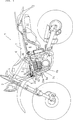
1 eine schematische Seitenansicht des Motorrads, das ein Abgassekundärluftventil gemäß einer Ausführungsform der Erfindung umfaßt; 1 a schematic side view of the motorcycle, comprising an exhaust secondary air valve according to an embodiment of the invention;
2 eine Seitenansicht eines Abgassekundärluftventils, an welchem eine Stütze angebracht ist; 2 a side view of an exhaust secondary air valve to which a support is attached;
3 eine von der Membrandeckelseite aus gesehene Seitenansicht eines Abgassekundärluftventils; 3 a side view of an exhaust secondary air valve as seen from the membrane lid side;
4 eine Ansicht längs der Richtung der in 3 durch einen Pfeil IV gezeigten Richtung; 4 a view along the direction of in 3 direction shown by an arrow IV;
5 eine Schnittansicht hauptsächlich längs der Linie V-V der 3, wobei Teile teilweise längs einer anderen Linie geschnitten sind; 5 a sectional view mainly along the line VV of 3 with parts partially cut along another line;
6 eine Draufsicht der Stütze, die zur Anbringung des Abgassekundärluftventils verwendet wird; und 6 a plan view of the support, which is used for mounting the exhaust secondary air valve; and
7 eine Seitenansicht, welche die Vorderseite der Stütze für das Abgassekundärluftventil zeigt. 7 a side view showing the front of the support for the exhaust secondary air valve.
1 ist eine schematische Seitenansicht des Motorrads 1 der Erfindung. Das Motorrad 1 besitzt eine Rahmenstruktur, die als Halb-Doppelschleife (semi-double cradle) bezeichnet wird, die ein Kopfrohr 2, einen Hauptrahmen 4, der sich von dem Kopfrohr 2 nach hinten erstreckt, während er durch eine in der Rückseite eines Kraftstofftanks 3 ausgebildete Ausnehmung hindurchgeht und einen Unterrahmen 5 umfaßt, der sich von dem Kopfrohr 2 nach unten erstreckt. Ein Motor 6, der unter dem Hauptrahmen 4 und hinter dem Unterrahmen 5 angeordnet ist, ist ein luftgekühlter OHV-Viertakt-Einzylindermotor, welcher einen Zylinder und zwei Einlaßventile und zwei Auslaßventile aufweist. 1 is a schematic side view of the motorcycle 1 the invention. The motorcycle 1 has a frame structure called a semi-double cradle, which is a head tube 2 , a main frame 4 that is from the head pipe 2 extends backwards while passing through one in the back of a fuel tank 3 trained recess passes and a subframe 5 which extends from the head pipe 2 extends downwards. An engine 6 that under the main frame 4 and behind the subframe 5 is an air-cooled OHV four-stroke single-cylinder engine having a cylinder and two intake valves and two exhaust valves.
Eine Kurbelwelle des Motors 6 erstreckt sich in der horizontalen Richtung des Fahrzeugs von rechts nach links und die Zylinderachslinie des Motors 6 ist nach vorne geneigt. Luft, die von einem unter einem Sitz 7 angeordneten Luftfilter 8 angesaugt wird, wird in einem Vergaser 9 mit Kraftstoff vermischt und das Luft-Kraftstoffgemisch wird vom Vergaser 9 in einen Brennraum des Motors 6 über einen Ansaugkrümmer und zwei Einlaßöffnungen geleitet, die an der Rückseite eines Zylinderkopfs 6a des Motors 6 geöffnet sind.A crankshaft of the engine 6 extends in the horizontal direction of the vehicle from right to left and the cylinder axis line of the engine 6 is tilted forward. Air coming from one under a seat 7 arranged air filter 8th is sucked in a carburetor 9 mixed with fuel and the air-fuel mixture is from the carburetor 9 in a combustion chamber of the engine 6 passed through an intake manifold and two intake ports, located at the back of a cylinder head 6a of the motor 6 are open.
Zwei Auspuffrohre 10 sind an der rechten Seite des Motors 6 in einem Zustand angeordnet, in welchem sie mit zwei an der Vorderseite des Zylinderkopfs 6a des Motors 6 öffnenden Auslaßöffnungen verbunden sind. Ein Auspuffrohr 11 ist mit den stromabwärtigen Enden der zwei Auspuffrohre 10 verbunden. Abgas, das durch die zwei Auspuffrohre 10 geströmt ist, wird in dem Auspuffrohr 11 gesammelt. In den Auspuffrohren 10 und 11 werden HC und CO in dem Abgas durch die dazu geleitete Abgassekundärluft oxidiert und das so gereinigte Abgas wird durch einen Schalldämpfer 12 an die Umgebungsluft abgegeben.Two exhaust pipes 10 are on the right side of the engine 6 arranged in a state in which they have two at the front of the cylinder head 6a of the motor 6 opening outlet openings are connected. An exhaust pipe 11 is with the downstream ends of the two exhaust pipes 10 connected. Exhaust gas flowing through the two exhaust pipes 10 has flowed, is in the exhaust pipe 11 collected. In the exhaust pipes 10 and 11 For example, HC and CO in the exhaust gas are oxidized by the secondary exhaust gas led thereto, and the thus purified exhaust gas is passed through a muffler 12 released into the ambient air.
Wie in den 1 bis 5 gezeigt ist, umfaßt ein Abgassekundärluftsystem ein Abgassekundärluftventil 20, ein Sekundärluftansaugrohr 22 (siehe 1), zwei Sekundärluftzufuhrrohre 25 (siehe 1) und zwei Sekundärluftzufuhrlöcher (nicht gezeigt). Das Sekundärluftansaugrohr 22 besitzt ein stromaufwärtiges Ende, das mit einer sauberen Seite des Luftfilters 8 in Verbindung steht und auch das stromabwärtige Ende, das mit einem Lufteinlaßrohr 21 des Abgassekundärluftventils 20 verbunden ist. Die Sekundärluftzufuhrrohre 25 weisen stromaufwärtige Enden auf, die mit zwei Luftauslaßrohren 23 des Abgassekundärluftventils 20 verbunden sind und auch stromabwärtige Enden, die mit zwei Verbindungsöffnungen 24 verbunden sind, die in einem Zylinderblock 6b ausgebildet sind. Die Sekundärluftzufuhröffnungen erstrecken sich längs des Zylinders von den Verbindungsöffnungen 24 zum Zylinderkopf 6a durch den Zylinderblock 6b und erstrecken sich ferner durch den Zylinderkopf 6a, um mit den Auslaßöffnungen in Verbindung zu stehen, die einen Teil des Auslaßkanals bilden. Jedes der Sekundärluftzufuhrrohre 25 besteht aus einem Schlauch 25a, der mit dem Luftauslaßrohr 23 verbunden ist und einem Rohr 25b, dessen eines Ende mit dem Schlauch 25a verbunden ist und dessen anderes Ende mit der Verbindungsöffnung 24 verbunden ist. Folglich wird die von dem Abgassekundärluftventil eingeleitete Sekundärluft durch die Sekundärluftzufuhrrohre 25 und die Sekundärluftzufuhrlöcher in die Auslaßöffnungen geleitet und wird in einem Zustand in die Auspuffrohre 10 und 11 geleitet, in dem sie mit dem von dem Brennraum strömenden Abgas vermischt ist.As in the 1 to 5 1, an exhaust secondary air system includes an exhaust secondary air valve 20 , a secondary air intake pipe 22 (please refer 1 ), two secondary air supply pipes 25 (please refer 1 ) and two secondary air supply holes (not shown). The secondary air intake pipe 22 has an upstream end with a clean side of the air filter 8th communicates and also the downstream end, with an air inlet pipe 21 the exhaust secondary air valve 20 connected is. The secondary air supply pipes 25 have upstream ends, with two air outlet pipes 23 the exhaust secondary air valve 20 are connected and also downstream ends, with two connection openings 24 connected in a cylinder block 6b are formed. The secondary air supply openings extend along the cylinder from the connection openings 24 to the cylinder head 6a through the cylinder block 6b and further extend through the cylinder head 6a to communicate with the outlet ports forming part of the exhaust passage. Each of the secondary air supply pipes 25 consists of a hose 25a that with the air outlet pipe 23 is connected and a pipe 25b whose one end is with the hose 25a is connected and the other end to the connection opening 24 connected is. Consequently, the secondary air introduced from the exhaust secondary air valve becomes through the secondary air supply pipes 25 and the secondary air supply holes are directed into the exhaust ports and in a state in the exhaust pipes 10 and 11 passed, in which it is mixed with the exhaust gas flowing from the combustion chamber.
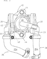
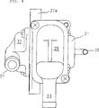
Die Struktur des Abgassekundärluftventils 20 wird unter Bezugnahme auf die 3 und 5 beschrieben. Das Abgassekundärluftventil 20 umfaßt einen Ventilkörper 27 mit einem Hohlraum 26. Zwei Montageflansche 27a, die einander entgegengesetzt angeordnet sind, sind derart ausgebildet, daß sie von dem Ventilkörper 27 nach außen vorstehen.The structure of the exhaust secondary air valve 20 is referring to the 3 and 5 described. The exhaust secondary air valve 20 comprises a valve body 27 with a cavity 26 , Two mounting flanges 27a , which are arranged opposite to each other, are formed such that they from the valve body 27 protrude outward.
Der Ventilkörper 27 besitzt zwei Öffnungsabschnitte 27c, welche mit dem Hohlraum 26 in Verbindung stehen und einander entgegengesetzt sind. Die Öffnungsabschnitte 27c sind in der Richtung rechtwinklig zu der Richtung, in der sich die Montageflansche 27a des Ventilkörpers 27 erstrecken. Ein Membranventil 28 und ein Membranventildeckel 29 zur Abdeckung des Membranventils 28 sind an jedem der Öffnungsabschnitte 27c angebracht. Der Membranventildeckel 29 ist mit dem Luftauslaßrohr 23 integriert. Das Membranventil 28 wird durch einen Abgasschwingungsdruck geöffnet/geschlossen, welcher in der Auslaßöffnung auftritt und durch das Sekundärluftzufuhrrohr 25 an das Membranventil 28 angelegt wird.The valve body 27 has two opening sections 27c which with the cavity 26 communicate and are opposite each other. The opening sections 27c are in the direction perpendicular to the direction in which the mounting flanges 27a of the valve body 27 extend. A diaphragm valve 28 and a diaphragm valve cover 29 to cover the diaphragm valve 28 are at each of the opening sections 27c appropriate. The diaphragm valve cover 29 is with the air outlet pipe 23 integrated. The diaphragm valve 28 is opened / closed by an exhaust vibration pressure which occurs in the exhaust port and through the secondary air supply pipe 25 to the diaphragm valve 28 is created.
Ein mit einem Unterdruckeinleitrohr 30 ausgebildeter Membrankammerdeckel 31 ist an einer Seitenfläche des Ventilkörpers 27 in der Achslinienrichtung eines Bolzenlochs 27b angebracht, das in dem Montageflansch 27a ausgebildet ist. Der Umfangsrand einer Membran 34 ist zwischen dem Ventilkörper 27 und dem Membrankammerdeckel 31 gehalten. Ein Schaft 33, an welchem ein Steuerventil 32 angebracht ist, ist an der Membran 34 befestigt. Eine Unterdruckkammer 35 ist zwischen der Membran 34 und dem Membrankammerdeckel 31 ausgebildet. Ein Unterdruck in dem Ansaugkrümmer wird in die Unterdruckkammer 35 über ein Unterdruckrohr 36 eingeleitet, das mit dem Unterdruckeinleitrohr 30 verbunden ist, um die Position des Steuerventils 32 auf der Basis des von dem Ansaugkrümmer zugeführten Unterdrucks zu steuern.One with a vacuum inlet tube 30 trained membrane chamber lid 31 is on a side surface of the valve body 27 in the axial direction of a bolt hole 27b mounted in the mounting flange 27a is trained. The peripheral edge of a membrane 34 is between the valve body 27 and the diaphragm chamber lid 31 held. A shaft 33 to which a control valve 32 is attached to the membrane 34 attached. A vacuum chamber 35 is between the membrane 34 and the diaphragm chamber lid 31 educated. A negative pressure in the intake manifold is in the vacuum chamber 35 via a vacuum pipe 36 initiated with the vacuum inlet tube 30 connected to the position of the control valve 32 on the basis of the supplied from the intake manifold vacuum.
Ein Öffnungsabschnitt 27d, der mit dem Hohlraum 26 in Verbindung steht, ist an der anderen Seitenfläche des Ventilkörpers 27 in der Achslinienrichtung des in dem Befestigungsflansch 27a ausgebildeten Bolzenlochs 27b ausgebildet und ist durch einen Lufteinlaßdeckel 37 mit einem Lufteinlaßrohr 21 abgedeckt. Der Öffnungsabschnitt 27d wird dafür verwendet, um von dem Lufteinlaßrohr 21 strömenden Luft zu der stromaufwärtigen Seite des Membranventils 28 zu leiten. Die Menge der durch den Öffnungsabschnitt 27d strömenden Luft, d. h. die Menge der in das Membranventil 28 strömenden Luft wird durch das Steuerventil 32 gesteuert, das an dem vorderen Ende des Schafts 33 angebracht ist, der sich durch den Hohlraum 26 und den Öffnungsabschnitt 27d erstreckt.An opening section 27d that with the cavity 26 communicates is on the other side surface of the valve body 27 in the axial direction of the in the mounting flange 27a trained bolt hole 27b is formed and is through an air inlet cover 37 with an air inlet pipe 21 covered. The opening section 27d is used to get from the air inlet pipe 21 flowing air to the upstream side of the diaphragm valve 28 to lead. The amount of through the opening section 27d flowing air, ie the amount of in the diaphragm valve 28 flowing air is through the control valve 32 controlled at the front end of the shaft 33 attached, extending through the cavity 26 and the opening section 27d extends.
Die Steuerung der Luftmenge, die durch das Steuerventil 32 basierend auf dem in dem Ansaugkrümmer erzeugten und in die Unterdruckkammer 35 eingeleiteten Unterdruck durchgeführt wird, wird unten beschrieben. Wenn der Unterdruck in dem Ansaugkrümmer groß ist, z. B. bei einer niedrigen Last des Motors 6, wird die Membran 34 in der 5 gegen die Federkraft einer Rückstellfeder 38 nach links bewegt und auf diese Weise wird das Steuerventil 32 auch nach links bewegt, mit dem Ergebnis, daß ein Spalt zwischen dem Öffnungsabschnitt 27d und dem Steuerventil 32 klein wird, um die dem Membranventil 28 zugeführte Luftmenge zu reduzieren. Wenn der Unterdruck in dem Ansaugkrümmer gering wird, z. B. zusammen mit der erhöhten Last des Motors 6, wird die Membran 34 in 5 nach rechts bewegt und auf diese Weise wird das Steuerventil 32 nach rechts bewegt, mit dem Ergebnis, daß ein Spalt zwischen dem Öffnungsabschnitt 27d und dem Steuerventil 32 groß wird, um die dem Membranventil 28 zugeführte Luftmenge zu erhöhen. Durch die Steuerung der dem Membranventil 28 zugeführten Luftmenge auf der Basis des Betriebszustands des Motors 6 kann, wie oben beschrieben, die Menge der den Auslaßöffnungen zugeführten Sekundärluft durch das Öffnen/Schließen des Membranventils 28 auf der Basis des Betriebszustands des Motors 6 gesteuert werden.The control of the amount of air passing through the control valve 32 based on that produced in the intake manifold and in the vacuum chamber 35 introduced negative pressure is described below. When the negative pressure in the intake manifold is large, e.g. B. at a low load of the engine 6 , the membrane becomes 34 in the 5 against the spring force of a return spring 38 moved to the left and in this way, the control valve 32 also moved to the left, with the result that a gap between the opening section 27d and the control valve 32 becomes small to the diaphragm valve 28 reduce the amount of air supplied. When the negative pressure in the intake manifold is low, z. B. together with the increased load of the engine 6 , the membrane becomes 34 in 5 moves to the right and in this way becomes the control valve 32 moved to the right, with the result that a gap between the opening section 27d and the control valve 32 gets big to the the diaphragm valve 28 increase the amount of air supplied. By controlling the diaphragm valve 28 supplied amount of air on the basis of the operating condition of the engine 6 can, as described above, the amount of the outlet openings supplied secondary air by the opening / closing of the diaphragm valve 28 based on the operating condition of the engine 6 to be controlled.
Die Montage des Abgassekundärluftventils 20 wird unter Bezugnahme auf die 1, 2, 6 und 7 beschrieben. Der Unterrahmen 5, an welchem das Abgassekundärluftventil 20 anzubringen ist, bildet zusammen mit dem Hauptrahmen 4 einen Teil der Rahmenstruktur zur Lagerung des Motors 6. Ein solcher Unterrahmen 5 ist in der Nähe des Motors 6 angeordnet. Insbesondere erstreckt sich der Unterrahmen 5 von dem Kopfrohr 2 nach unten, während er durch eine an der Vorderseite des Kraftstoffttanks 3 ausgebildete Ausnehmung geht und erstreckt sich weiter an der Vorderseite des Motors 6 im wesentlichen parallel zur Achslinie des Zylinders des Motors 6 nach unten.The installation of the exhaust secondary air valve 20 is referring to the 1 . 2 . 6 and 7 described. The subframe 5 at which the exhaust secondary air valve 20 is to be installed together with the main frame 4 a part of the frame structure for mounting the engine 6 , Such a subframe 5 is near the engine 6 arranged. In particular, the subframe extends 5 from the head pipe 2 down while passing through one at the front of the fuel tank 3 formed recess goes and extends further to the front of the engine 6 substantially parallel to the axis line of the cylinder of the engine 6 downward.
Das Abgassekundärluftventil 20 ist unter Verwendung einer in den 6 und 7 gezeigten Stütze 40 an der linken Seite (an der Vorderseite der Papierebene in 1) des Unterrahmens 5 an einer Position angebracht, welche unter der obigen Ausnehmung angeordnet ist, die an der Vorderseite des Kraftstofftanks 3 ausgebildet ist und welche über einem Abschnitt angeordnet ist, wo eine virtuelle Ebene, die eine Berührungsebene des Zylinderkopfdeckels 6c mit dem Zylinderkopf 6a einschließt, den Unterrahmen 5 kreuzt.The exhaust secondary air valve 20 is using one in the 6 and 7 shown prop 40 on the left side (at the front of the paper plane in 1 ) of the subframe 5 mounted at a position which is located under the above recess, which at the front of the fuel tank 3 is formed and which is disposed above a portion where a virtual plane, the contact plane of the cylinder head cover 6c with the cylinder head 6a includes the subframe 5 crosses.
Die Stütze 40 ist ein plattenartiges Element, das annähernden L-förmig gebogen ist. In dieser Stütze 40 sind zwei zylindrische Muttern 41 an einem Ende der L-förmigen Abschnitte befestigt und zwei Löcher 43, in welche Gummitüllen 42 einzusetzen sind, sind in dem anderen der L-förmigen Abschnitte ausgebildet. Bolzen 44, die durch die Bolzenlöcher 27b hindurchgehen, die an den Montageflanschen 27a des Abgassekundärluftventils 20 ausgebildet sind, sind mit Muttern 41 der Stütze 40 verschraubt, wodurch das Abgassekundärluftventil 20 an der Stütze 40 befestigt ist. Die so mit dem Sekundärluftventil 20 aufgebaute Stütze 40 ist an dem Unterrahmen 5 durch die Gummitüllen 42 befestigt.The support 40 is a plate-like element that is bent approximately L-shaped. In this prop 40 are two cylindrical nuts 41 attached to one end of the L-shaped sections and two holes 43 , in which rubber grommets 42 are to be inserted, are formed in the other of the L-shaped portions. bolt 44 passing through the bolt holes 27b go through, on the mounting flanges 27a the exhaust secondary air valve 20 are formed, are with nuts 41 the prop 40 bolted, causing the exhaust secondary air valve 20 on the prop 40 is attached. The way with the secondary air valve 20 built-up support 40 is on the subframe 5 through the rubber grommets 42 attached.
Da der Unterrahmen zur Lagerung des Motors 6 nahe dem Motor 6 angeordnet ist, während er sich zum Motor 6 nach unten erstreckt, der an der unteren Seite des Fahrzeugs angeordnet ist, ist das an dem Unterrahmen 5 angebrachte Abgassekundärluftventil 20 im Vergleich zu Abgassekundärluftsystemen vom Stand der Technik näher an dem Motor 6 angeordnet. Folglich wird die Länge der Sekundärluftzufuhrrohre 25, die sich von dem Abgassekundärluftventil 20 zum Motor 6 erstrecken, kürzer und auf diese Weise wird das Abgassekundärluftsystem einschließlich der Sekundärluftzufuhrrohre 25 kompakt. Da die Länge der Sekundärluftzufuhrrohre 25 wie oben beschrieben kurz ist, wird der Strömungswiderstand in den Rohren 25 klein, so daß es einfach wird, die notwendige Sekundärluftmenge sicherzustellen.As the subframe for storage of the engine 6 near the engine 6 is arranged while turning to the engine 6 extends downwards, which is arranged on the lower side of the vehicle, that is on the subframe 5 attached exhaust secondary air valve 20 compared to exhaust gas secondary systems of the prior art closer to the engine 6 arranged. Consequently, the length of the secondary air supply pipes becomes 25 extending from the exhaust secondary air valve 20 to the engine 6 extend, shorter and thus the exhaust secondary air system including the secondary air supply pipes 25 compact. As the length of the secondary air supply pipes 25 As described above, the flow resistance in the tubes becomes 25 small, so that it becomes easy to ensure the necessary secondary air quantity.
Da jeweilige Komponenten des Fahrzeugs einschließlich des Kraftstofftanks 3 und des Motors 6 hinter dem Unterrahmen 5 angeordnet sind, ist um den Unterrahmen 5 ein relativ großer Raum vorhanden. Insbesondere, wie in 1 gezeigt ist, ist um die oben beschrieben Montageposition des Abgassekundärluftventils 20 ein relativ weiter Raum ausgebildet, da die untere Fläche des Kraftstofftanks 3, der über der obigen Montageposition angeordnet ist, gebogen ist und auch die obere Fläche des Zylinderkopfdeckels 6c, der unter der obigen Montageposition angeordnet ist, geneigt ist und das Abgassekundärluftventil 20 ist in einem solchen relativ weiten Raum angeordnet.As are the respective components of the vehicle including the fuel tank 3 and the engine 6 behind the subframe 5 are arranged around the subframe 5 a relatively large space available. In particular, as in 1 is shown, is the mounting position of the exhaust secondary air valve described above 20 a relatively wider space is formed as the bottom surface of the fuel tank 3 , which is located above the above mounting position, bent and also the upper surface of the cylinder head cover 6c which is located below the above mounting position, inclined and the exhaust secondary air valve 20 is arranged in such a relatively wide space.
Da der über dem obigen Montageraum angeordnete Kraftstofftank 3 und der unter dem obigen Montageraum angeordnete Motor 6 jeweils eine Quergröße (in der Breitenrichtung des Fahrzeugs) besitzen, die größer als die des Abgassekundärluftventils 20 ist, ist das Abgassekundärluftventil 20 zwischen beiden Querendflächen sowohl des Kraftstofftanks 3 als auch des Motors 6 angeordnet. Daher besteht nur eine geringe Möglichkeit, daß das Abgassekundärluftventil 20 mit dem Boden in Kontakt gebracht wird, wenn das Fahrzeug horizontal auf den Boden gelegt wird.Since the above the mounting space arranged fuel tank 3 and the engine arranged below the above mounting space 6 each have a transverse size (in the width direction of the vehicle) greater than that of the exhaust secondary air valve 20 is, is the exhaust secondary air valve 20 between both transverse end surfaces of both the fuel tank 3 as well as the engine 6 arranged. Therefore, there is little possibility that the exhaust secondary air valve 20 is brought into contact with the ground when the vehicle is laid horizontally on the ground.
Das mit dem Lufteinlaßrohr 21 verbundene Sekundärluftansaugrohr 22 des Abgassekundärluftventils 20, das in dem oben beschriebenen Montageraum angeordnet ist, ist hinter dem Motor 6 mit dem Luftfilter 8 verbunden. Insbesondere ist das Sekundärluftansaugrohr 22 auf der Seite, die den Auspuffrohren 10 entgegengesetzt ist, in einem länglichem Raum zwischen der unteren Fläche des Kraftstofftanks 3 und der oberen Fläche des Zylinderkopfsdeckels 6c derart angeordnet, daß es sich in einer annähernd geraden Linie, mit einem leicht gebogenen Abschnitt zwischen beiden Querendflächen sowohl vom Kraftstofftank 3 als auch vom Zylinderkopfdeckel 6c erstreckt.That with the air inlet tube 21 Connected secondary air intake pipe 22 the exhaust secondary air valve 20 located in the above-described mounting space is behind the engine 6 with the air filter 8th connected. In particular, the Sekundärluftansaugrohr 22 on the side, the exhaust pipes 10 is opposite, in an oblong space between the lower surface of the fuel tank 3 and the top surface of the cylinder head cover 6c arranged so that it is in an approximately straight line, with a slightly curved portion between both transverse end surfaces of both the fuel tank 3 as well as from the cylinder head cover 6c extends.
Das Abgassekundärluftventil 20 ist an dem Unterrahmen 5 angebracht, welcher vor der Vorderseite des Motors 6 mit den Auslaßöffnungen und den Verbindungsöffnungen 24 angeordnet ist. Die Luftauslaßrohre 23 des vor dem Motor 6 angeordnet Abgassekundärluftventils 20 sind mit den Verbindungsöffnungen 24 an der Vorderseite des Motors 6 mittels der Sekundärluftzufuhrrohre 25 verbunden.The exhaust secondary air valve 20 is on the subframe 5 attached, which is in front of the front of the engine 6 with the outlet openings and the connection openings 24 is arranged. The air outlet pipes 23 in front of the engine 6 disposed Exhaust secondary air valve 20 are with the connection openings 24 at the front of the engine 6 by means of the secondary air supply pipes 25 connected.
Da die zwei Luftauslaßrohre 23, mit welchen die Sekundärluftzufuhrrohre 25 verbunden sind, nach unten hin geöffnet sind, sind die Sekundärluftzufuhrrohre 25 mit den Verbindungsöffnungen 24, die unter den Luftauslaßrohren 23 angeordnet sind, ohne irgendwelche Biegungen mit einem großen Radius verbunden. Wie oben beschrieben, besitzen die Sekundärluftzufuhrrohre 25 eine kurze Länge, da das Abgassekundärluftventil 20 näher an dem Motor 6 angeordnet ist. Zusätzlich dazu wird die Länge der Rohre 25 kürzer, da die Luftauslaßrohre 23 nach unten hin geöffnet sind.Because the two air outlet pipes 23 with which the secondary air supply pipes 25 are connected, are open to the bottom, are the secondary air supply pipes 25 with the connection openings 24 that under the air outlet pipes 23 are arranged without any bends connected to a large radius. As described above, the secondary air supply pipes have 25 a short length, as the exhaust secondary air valve 20 closer to the engine 6 is arranged. In addition to this, the length of the tubes 25 shorter, because the air outlet pipes 23 are open at the bottom.
Das, wie oben beschrieben, näher am Motor 6 angeordnete Abgassekundärluftventil 20 wird durch die von dem Motor 6 und den Auspuffrohren 10 und 11 abgegebene Wärme erwärmt. Da jedoch der Motor 6 luftgekühlt ist und so der Unterrahmen 5 an einer dem Fahrtwind ausgesetzten Position angeordnet ist, sind das Abgassekundärluftventil 20 und die Sekundärluftzufuhrrohre 25, die an dem Unterrahmen 5 angebracht sind, auch ausreichend dem Fahrtwind ausgesetzt und werden durch den Fahrtwind gekühlt. Daher wird das Abgassekundärluftventil 20 und die Sekundärluftzufuhrrohre 25 ungeachtet der vorhandenen Wärmequelle nicht auf eine übermäßig hohe Temperatur erwärmt.This, as described above, closer to the engine 6 arranged exhaust secondary air valve 20 gets through by the engine 6 and the exhaust pipes 10 and 11 heated heat. However, because the engine 6 air cooled and so is the subframe 5 is arranged at a position exposed to the wind, are the exhaust secondary air valve 20 and the secondary air supply pipes 25 attached to the subframe 5 are mounted sufficiently exposed to the wind and are cooled by the wind. Therefore, the exhaust secondary air valve 20 and the secondary air supply pipes 25 regardless of the existing heat source is not heated to an excessively high temperature.
Diese Ausführungsform mit der obigen Konfiguration weist die folgenden Effekte auf:
Da der Unterrahmen 5 zur Lagerung des Motors 6 nahe am Motor 6 angeordnet ist, während er sich zum Motor 6 nach unten hin erstreckt, ist das das am Unterrahmen 5 angebrachte Abgassekundärluftventil 20 auch in der Nähe des Motors 6 angeordnet. Folglich kann die Länge der sich von dem Abgassekundärluftventil 20 zum Motor 6 erstreckenden Sekundärluftzufuhrrohre 25 gekürzt werden und auf diese Weise kann das Abgassekundärluftsystem einschließlich der Sekundärluftzufuhrrohre 25 kompakt gestaltet werden. Da die Länge der Rohre 25 kurz ist, wird der Strömungswiderstand der Rohre 25 klein, so daß es möglich ist, die notwendige Sekundärluftmenge sicherzustellen.This embodiment having the above configuration has the following effects:
As the subframe 5 for storage of the engine 6 close to the engine 6 is arranged while turning to the engine 6 extends downwards, this is the subframe 5 attached exhaust secondary air valve 20 also near the engine 6 arranged. Consequently, the length of the exhaust from the secondary air valve 20 to the engine 6 extending secondary air supply pipes 25 be shortened and in this way can the exhaust secondary air system including the secondary air supply pipes 25 be made compact. Because the length of the pipes 25 short, is the flow resistance of the pipes 25 small, so that it is possible to ensure the necessary secondary air quantity.
Da das Abgassekundärluftventil 20 in dem zwischen dem Kraftstofftank 3 und dem Motor ausgebildeten Raum an einer Position über dem Abschnitt angeordnet ist, wo eine virtuelle Ebene, welche eine Berührungsebene des Zylinderkopfdeckels 6c mit dem Zylinderkopfdeckel 6a einschließt, den Unterrahmen 5 kreuzt, kann die Länge der Sekundärluftzufuhrrohre 25 vom Abgassekundärluftventil 20 zum Motor 6 verkürzt werden und ebenso kann das Abgassekundärluftventil 20 angeordnet werden, ohne daß sich nachteilige Effekte auf die Anordnung der Randkomponenten des Fahrzeugs zeigen. Das Abgassekundärluftventil 20 ist auch in dem Raum angeordnet, während es zwischen den Querendflächen sowohl des Kraftstofftanks 3 als auch des Motors 6 angeordnet ist und folglich kann das Abgassekundärluftventil 20 weniger in Kontakt mit dem Boden gebracht werden und auf diese Weise ist es weniger anfällig für eine Beschädigung infolge des Kontakts mit dem Boden, sogar wenn das Fahrzeug horizontal auf den Boden gelegt wird.Because the exhaust secondary air valve 20 in between the fuel tank 3 and the engine-formed space is disposed at a position above the portion where a virtual plane which is a contact plane of the cylinder head cover 6c with the cylinder head cover 6a includes the subframe 5 can cross the length of the secondary air supply pipes 25 from the exhaust secondary air valve 20 to the engine 6 be shortened and also the exhaust secondary air valve 20 can be arranged without showing any adverse effects on the arrangement of the edge components of the vehicle. The exhaust secondary air valve 20 is also arranged in the space while it is between the transverse end surfaces of both the fuel tank 3 as well as the engine 6 is arranged, and thus the exhaust secondary air valve 20 less in contact with the ground and in this way it is less prone to damage due to contact with the ground, even when the vehicle is laid horizontally on the ground.
Die Sekundärluftzufuhrrohre 25 sind an dem Unterrahmen 5 angebracht, der vor der Vorderseite des die Verbindungsöffnungen 24 aufweisenden Motors 6 angeordnet ist und ferner sind sie von den nach unten geöffneten Luftauslaßrohren 23 mit den unter den Luftauslaßrohren 23 angeordneten Verbindungsöffnungen 24 verbunden, so daß die Länge der Sekundärluftrohre 25 weiter verkürzt werden kann. Da die Sekundärluftzufuhrrohre 25 dem Fahrtwind ausgesetzt sind und auf diese Weise durch den Fahrtwind gekühlt werden, wird ferner die in den Sekundärluftzufuhrrohren 25 strömende Luft nicht auf eine übermäßig hohe Temperatur aufgewärmt, mit dem Ergebnis, daß es möglich ist, die Dichteverminderung der Luft zu verringern und folglich die Verringerung des Abgasreinigungsverhältnisses zu unterdrücken.The secondary air supply pipes 25 are on the subframe 5 attached, in front of the front of the connection openings 24 having engine 6 is arranged and further they are from the downwardly open air outlet pipes 23 with the under the air outlet pipes 23 arranged connection openings 24 connected so that the length of the secondary air pipes 25 can be shortened further. Because the secondary air supply pipes 25 are exposed to the wind and are cooled in this way by the wind, is also in the secondary air supply pipes 25 flowing air is not warmed up to an excessively high temperature, with the result that it is possible to reduce the density reduction of the air and thus to suppress the reduction of the exhaust gas purification ratio.
Da das an dem Unterrahmen 5 angebrachte Abgassekundärluftventil 20 dem Fahrtwind ausreichend ausgesetzt ist und so durch den Fahrtwind gekühlt wird, wird es nicht auf eine übermäßig hohe Temperatur erwärmt. Daher ist es möglich, die Haltbarkeit des Abgassekundärluftventils 20 zu verbessern.As that on the subframe 5 attached exhaust secondary air valve 20 is sufficiently exposed to the wind and is cooled by the airstream, it is not heated to an excessively high temperature. Therefore, it is possible the durability of the exhaust secondary air valve 20 to improve.
Da das Abgassekundärluftventil 20 an dem einen Teil der vorhandenen Rahmenstruktur des Fahrzeugs bildenden Unterrahmen 5 durch die Stütze 40 angebracht ist, ist es nicht notwendig, von neuem eine Montageplatte vorzusehen, wie es bei der oben beschriebenen Struktur vom Stand der Technik der Fall ist.Because the exhaust secondary air valve 20 on the part of the existing frame structure of the vehicle forming subframe 5 through the support 40 is attached, it is not necessary to provide again a mounting plate, as is the case with the above-described structure of the prior art.
Da das Sekundärluftansaugrohr 22 nahe dem Zylinderkopfdeckel 6c an der Seite angeordnet ist, die der Seite gegenüberliegt, an welcher die Auspuffrohre 10 und 11 angeordnet sind, ist es möglich, den nachteiligen Effekt der Erwärmung infolge der Auspuffrohre 10 und 11 zu reduzieren, der sich bei der Sekundärluft zeigen und folglich die Dichteverminderung der dem Membranventil 28 zugeführten Luft zu vermindern. Da auch das Sekundärluftansaugrohr 22 in der annähernd geraden Linie angeordnet ist, ist es möglich, die Länge des Rohrs 22 zu verkürzen.Since the secondary air intake pipe 22 near the cylinder head cover 6c is arranged on the side opposite to the side where the exhaust pipes 10 and 11 are arranged, it is possible the adverse effect of heating due to the exhaust pipes 10 and 11 to reduce, which are reflected in the secondary air and consequently the density reduction of the diaphragm valve 28 to reduce the supply of air. As the secondary air intake pipe 22 is arranged in the approximately straight line, it is possible the length of the pipe 22 To shorten.
In der oben beschriebenen Ausführungsform weist das Abgassekundärluftventil 20 das Steuerventil 32 auf; jedoch ist die Erfindung nicht darauf beschränkt. Beispielsweise kann das Abgassekundärluftventil 20 ohne Steuerventil 32 vorgesehen sein, d. h. es kann nur mit dem Membranventil 28 versehen sein. Ferner kann das Membranventil 28 durch ein anderes Ventil wie z. B. ein druckempfindliches Ventil oder ein Magnetventil ersetzt werden.In the embodiment described above, the exhaust secondary air valve 20 the control valve 32 on; however, the invention is not limited thereto. For example, the exhaust secondary air valve 20 without control valve 32 be provided, ie it can only with the diaphragm valve 28 be provided. Furthermore, the diaphragm valve 28 through another valve such. B. a pressure-sensitive valve or a solenoid valve can be replaced.
Während das Abgassekundärluftventil 20 an der linken Seite des Unterrahmens 5 in der obigen Ausführungsform angeordnet ist, kann es auch an der rechten, Vorder- oder Rückseite des Unterrahmens 5 angebracht sein.While the exhaust secondary air valve 20 on the left side of the subframe 5 In the above embodiment, it may also be on the right, front or back of the subframe 5 to be appropriate.
In der obigen Ausführungsform ist das Abgassekundärluftventil 20 an der Position angeordnet, welche über dem Abschnitt angeordnet ist, wo die virtuelle Ebene, welche die Berührungsebene des Zylinderkopfdeckels 6c mit dem Zylinderkopf 6a einschließt, den Unterrahmen 5 kreuzt und welche unter dem Kraftstofftank 3 ist; jedoch kann es an irgendeinem anderen Montageabschnitt als dem obigen Abschnitt insoweit befestigt werden, als ein solcher Montageabschnitt einen Raum aufweist, der das Abgassekundärluftventil 20 aufnehmen kann.In the above embodiment, the exhaust secondary air valve 20 arranged at the position which is disposed above the portion where the virtual plane which the contact plane of the cylinder head cover 6c with the cylinder head 6a includes the subframe 5 crosses and which under the fuel tank 3 is; however, it may be attached to any mounting portion other than the above portion insofar as such a mounting portion has a space containing the exhaust secondary air valve 20 can record.
Um ein Abgassekundärluftsystem vorzusehen, das dafür bestimmt ist, die mit einem Abgassekundärluftventil verbundenen Sekundärluftzufuhrrohre in der Länge zu verkürzen, um auf diese Weise das Abgassekundärluftventil einschließlich der Sekundärluftzufuhrrohre kompakt zu gestalten und auch das Abgassekundärluftventil und die Sekundärluftzufuhrrohre durch Fahrtwind zu kühlen, wird ein Fahrzeug 1 vom Satteltyp vorgeschlagen, das einen Hauptrahmen 4 umfaßt, der sich von einem Kopfrohr 2 nach hinten erstreckt; einen Unterrahmen 5, der sich von dem Kopfrohr 2 nach unten erstreckt; einen Motor 6, der unter dem Hauptrahmen 4 und hinter dem Unterrahmen 5 angeordnet ist; und ein Abgassekundärluftventil 20, das mit einem Sekundärluftzufuhrrohr 25 verbunden ist, um Sekundärluft zu einem Auslaßkanal des Motors 6 über das Sekundärluftzufuhrrohr 25 zuzuführen; wobei das Abgassekundärluftventil 20 an dem Unterrahmen 5 angebracht ist.To provide an exhaust secondary air system designed to shorten the secondary air supply pipes connected to an exhaust secondary air valve in length so as to make the exhaust secondary air valve including the secondary air supply pipes compact and also to cool the exhaust secondary air valve and the secondary air supply pipes by wind, becomes a vehicle 1 proposed by the saddle type, which is a main frame 4 which extends from a head pipe 2 extends to the rear; a subframe 5 that is from the head pipe 2 extends downwards; an engine 6 that under the main frame 4 and behind the subframe 5 is arranged; and an exhaust secondary air valve 20 that with a secondary air supply pipe 25 is connected to secondary air to an exhaust passage of the engine 6 via the secondary air supply pipe 25 supply; wherein the exhaust secondary air valve 20 on the subframe 5 is appropriate.