DE102008061843A1 - Heterocyclic compounds and their use in electronic and optoelectronic devices - Google Patents
Heterocyclic compounds and their use in electronic and optoelectronic devices Download PDFInfo
- Publication number
- DE102008061843A1 DE102008061843A1 DE102008061843A DE102008061843A DE102008061843A1 DE 102008061843 A1 DE102008061843 A1 DE 102008061843A1 DE 102008061843 A DE102008061843 A DE 102008061843A DE 102008061843 A DE102008061843 A DE 102008061843A DE 102008061843 A1 DE102008061843 A1 DE 102008061843A1
- Authority
- DE
- Germany
- Prior art keywords
- independently selected
- formula
- heteroaryl
- aryl
- fused
- Prior art date
- Legal status (The legal status is an assumption and is not a legal conclusion. Google has not performed a legal analysis and makes no representation as to the accuracy of the status listed.)
- Granted
Links
- 150000002391 heterocyclic compounds Chemical class 0.000 title claims abstract description 15
- 230000005693 optoelectronics Effects 0.000 title claims abstract description 13
- 239000000463 material Substances 0.000 claims abstract description 42
- 230000000903 blocking effect Effects 0.000 claims abstract description 4
- 239000004065 semiconductor Substances 0.000 claims description 23
- 125000000623 heterocyclic group Chemical group 0.000 claims description 18
- 125000003118 aryl group Chemical group 0.000 claims description 17
- 125000001072 heteroaryl group Chemical group 0.000 claims description 17
- 239000002019 doping agent Substances 0.000 claims description 16
- 125000000217 alkyl group Chemical group 0.000 claims description 14
- XTCBADXSNZHEGE-UHFFFAOYSA-N [1,4]benzoxathiino[2,3-b]phenoxathiine Chemical compound O1C2=CC=CC=C2SC2=C1C=C1SC3=CC=CC=C3OC1=C2 XTCBADXSNZHEGE-UHFFFAOYSA-N 0.000 claims description 8
- NINIDFKCEFEMDL-UHFFFAOYSA-N Sulfur Chemical compound [S] NINIDFKCEFEMDL-UHFFFAOYSA-N 0.000 claims description 6
- 229910052717 sulfur Inorganic materials 0.000 claims description 6
- 239000011593 sulfur Substances 0.000 claims description 6
- QVGXLLKOCUKJST-UHFFFAOYSA-N atomic oxygen Chemical group [O] QVGXLLKOCUKJST-UHFFFAOYSA-N 0.000 claims description 5
- 239000004020 conductor Substances 0.000 claims description 5
- 229910052760 oxygen Inorganic materials 0.000 claims description 5
- 239000001301 oxygen Substances 0.000 claims description 5
- 239000001257 hydrogen Substances 0.000 claims description 4
- 229910052739 hydrogen Inorganic materials 0.000 claims description 4
- JMEPFIVYXZGLAK-UHFFFAOYSA-N 3,10-dimethoxy-[1,4]benzoxathiino[2,3-b]phenoxathiine Chemical compound O1C2=CC(OC)=CC=C2SC2=C1C=C1SC3=CC=C(OC)C=C3OC1=C2 JMEPFIVYXZGLAK-UHFFFAOYSA-N 0.000 claims description 3
- JSEOTMGRQLSQLD-UHFFFAOYSA-N 6-n,6-n,13-n,13-n-tetraphenyl-[1,4]benzoxathiino[2,3-b]phenoxathiine-6,13-diamine Chemical compound C1=CC=CC=C1N(C=1C=2SC3=CC=CC=C3OC=2C(N(C=2C=CC=CC=2)C=2C=CC=CC=2)=C2SC3=CC=CC=C3OC2=1)C1=CC=CC=C1 JSEOTMGRQLSQLD-UHFFFAOYSA-N 0.000 claims description 3
- BUGBHKTXTAQXES-UHFFFAOYSA-N Selenium Chemical compound [Se] BUGBHKTXTAQXES-UHFFFAOYSA-N 0.000 claims description 3
- 230000005669 field effect Effects 0.000 claims description 3
- 229910052711 selenium Inorganic materials 0.000 claims description 3
- 239000011669 selenium Substances 0.000 claims description 3
- 229910052714 tellurium Inorganic materials 0.000 claims description 3
- PORWMNRCUJJQNO-UHFFFAOYSA-N tellurium atom Chemical compound [Te] PORWMNRCUJJQNO-UHFFFAOYSA-N 0.000 claims description 3
- SOYPNUWPKJXVQM-UHFFFAOYSA-N 3,13,23-trioxa-10,20,30-trithiaheptacyclo[20.8.0.02,11.04,9.012,21.014,19.024,29]triaconta-1,4,6,8,11,14,16,18,21,24,26,28-dodecaene Chemical class S1C2=CC=CC=C2OC2=C1C(OC1=CC=CC=C1S1)=C1C1=C2SC2=CC=CC=C2O1 SOYPNUWPKJXVQM-UHFFFAOYSA-N 0.000 claims description 2
- FUETVUCFQSZUOA-UHFFFAOYSA-N S1C2=CC=CC=C2OC2=C1C=C1OC(C=C3SC4=CC=CC=C4OC3=C3)=C3SC1=C2 Chemical compound S1C2=CC=CC=C2OC2=C1C=C1OC(C=C3SC4=CC=CC=C4OC3=C3)=C3SC1=C2 FUETVUCFQSZUOA-UHFFFAOYSA-N 0.000 claims description 2
- 150000002431 hydrogen Chemical class 0.000 claims 2
- 125000002837 carbocyclic group Chemical group 0.000 claims 1
- 239000010410 layer Substances 0.000 description 95
- ZMXDDKWLCZADIW-UHFFFAOYSA-N N,N-Dimethylformamide Chemical compound CN(C)C=O ZMXDDKWLCZADIW-UHFFFAOYSA-N 0.000 description 39
- OKKJLVBELUTLKV-UHFFFAOYSA-N Methanol Chemical compound OC OKKJLVBELUTLKV-UHFFFAOYSA-N 0.000 description 30
- HEDRZPFGACZZDS-UHFFFAOYSA-N Chloroform Chemical compound ClC(Cl)Cl HEDRZPFGACZZDS-UHFFFAOYSA-N 0.000 description 22
- 238000006243 chemical reaction Methods 0.000 description 18
- 239000007787 solid Substances 0.000 description 16
- 239000002800 charge carrier Substances 0.000 description 14
- XLYOFNOQVPJJNP-UHFFFAOYSA-N water Substances O XLYOFNOQVPJJNP-UHFFFAOYSA-N 0.000 description 12
- 238000000034 method Methods 0.000 description 11
- 239000000203 mixture Substances 0.000 description 11
- YXFVVABEGXRONW-UHFFFAOYSA-N Toluene Chemical compound CC1=CC=CC=C1 YXFVVABEGXRONW-UHFFFAOYSA-N 0.000 description 9
- 150000001875 compounds Chemical class 0.000 description 9
- 239000000243 solution Substances 0.000 description 9
- 239000012074 organic phase Substances 0.000 description 8
- 239000000758 substrate Substances 0.000 description 8
- 239000000725 suspension Substances 0.000 description 8
- VMKYTRPNOVFCGZ-UHFFFAOYSA-N 2-sulfanylphenol Chemical compound OC1=CC=CC=C1S VMKYTRPNOVFCGZ-UHFFFAOYSA-N 0.000 description 7
- 238000002290 gas chromatography-mass spectrometry Methods 0.000 description 7
- 239000010409 thin film Substances 0.000 description 7
- 208000033962 Fontaine progeroid syndrome Diseases 0.000 description 6
- 229910052782 aluminium Inorganic materials 0.000 description 6
- BOXSCYUXSBYGRD-UHFFFAOYSA-N cyclopenta-1,3-diene;iron(3+) Chemical compound [Fe+3].C=1C=C[CH-]C=1.C=1C=C[CH-]C=1 BOXSCYUXSBYGRD-UHFFFAOYSA-N 0.000 description 6
- KTWOOEGAPBSYNW-UHFFFAOYSA-N ferrocene Chemical compound [Fe+2].C=1C=C[CH-]C=1.C=1C=C[CH-]C=1 KTWOOEGAPBSYNW-UHFFFAOYSA-N 0.000 description 6
- 238000002347 injection Methods 0.000 description 6
- 239000007924 injection Substances 0.000 description 6
- 239000012044 organic layer Substances 0.000 description 6
- BWHMMNNQKKPAPP-UHFFFAOYSA-L potassium carbonate Chemical compound [K+].[K+].[O-]C([O-])=O BWHMMNNQKKPAPP-UHFFFAOYSA-L 0.000 description 6
- 239000000047 product Substances 0.000 description 6
- 239000011541 reaction mixture Substances 0.000 description 6
- 239000002904 solvent Substances 0.000 description 6
- 238000003786 synthesis reaction Methods 0.000 description 6
- 230000015572 biosynthetic process Effects 0.000 description 5
- 230000005525 hole transport Effects 0.000 description 5
- 239000011159 matrix material Substances 0.000 description 5
- 239000011368 organic material Substances 0.000 description 5
- 230000007704 transition Effects 0.000 description 5
- STTGYIUESPWXOW-UHFFFAOYSA-N 2,9-dimethyl-4,7-diphenyl-1,10-phenanthroline Chemical compound C=12C=CC3=C(C=4C=CC=CC=4)C=C(C)N=C3C2=NC(C)=CC=1C1=CC=CC=C1 STTGYIUESPWXOW-UHFFFAOYSA-N 0.000 description 4
- XKRFYHLGVUSROY-UHFFFAOYSA-N Argon Chemical compound [Ar] XKRFYHLGVUSROY-UHFFFAOYSA-N 0.000 description 4
- CSNNHWWHGAXBCP-UHFFFAOYSA-L Magnesium sulfate Chemical compound [Mg+2].[O-][S+2]([O-])([O-])[O-] CSNNHWWHGAXBCP-UHFFFAOYSA-L 0.000 description 4
- PMZURENOXWZQFD-UHFFFAOYSA-L Sodium Sulfate Chemical compound [Na+].[Na+].[O-]S([O-])(=O)=O PMZURENOXWZQFD-UHFFFAOYSA-L 0.000 description 4
- UIIMBOGNXHQVGW-UHFFFAOYSA-M Sodium bicarbonate Chemical compound [Na+].OC([O-])=O UIIMBOGNXHQVGW-UHFFFAOYSA-M 0.000 description 4
- 238000009792 diffusion process Methods 0.000 description 4
- ZQBFAOFFOQMSGJ-UHFFFAOYSA-N hexafluorobenzene Chemical compound FC1=C(F)C(F)=C(F)C(F)=C1F ZQBFAOFFOQMSGJ-UHFFFAOYSA-N 0.000 description 4
- 238000004519 manufacturing process Methods 0.000 description 4
- 238000005259 measurement Methods 0.000 description 4
- 229910052751 metal Inorganic materials 0.000 description 4
- 239000002184 metal Substances 0.000 description 4
- 238000010992 reflux Methods 0.000 description 4
- 229910052938 sodium sulfate Inorganic materials 0.000 description 4
- 235000011152 sodium sulphate Nutrition 0.000 description 4
- TVIVIEFSHFOWTE-UHFFFAOYSA-K tri(quinolin-8-yloxy)alumane Chemical compound [Al+3].C1=CN=C2C([O-])=CC=CC2=C1.C1=CN=C2C([O-])=CC=CC2=C1.C1=CN=C2C([O-])=CC=CC2=C1 TVIVIEFSHFOWTE-UHFFFAOYSA-K 0.000 description 4
- XEKOWRVHYACXOJ-UHFFFAOYSA-N Ethyl acetate Chemical compound CCOC(C)=O XEKOWRVHYACXOJ-UHFFFAOYSA-N 0.000 description 3
- KWYUFKZDYYNOTN-UHFFFAOYSA-M Potassium hydroxide Chemical compound [OH-].[K+] KWYUFKZDYYNOTN-UHFFFAOYSA-M 0.000 description 3
- 239000004411 aluminium Substances 0.000 description 3
- 239000004305 biphenyl Substances 0.000 description 3
- 230000008859 change Effects 0.000 description 3
- 239000012043 crude product Substances 0.000 description 3
- 230000000694 effects Effects 0.000 description 3
- 238000002848 electrochemical method Methods 0.000 description 3
- 238000000589 high-performance liquid chromatography-mass spectrometry Methods 0.000 description 3
- AMGQUBHHOARCQH-UHFFFAOYSA-N indium;oxotin Chemical compound [In].[Sn]=O AMGQUBHHOARCQH-UHFFFAOYSA-N 0.000 description 3
- 238000004768 lowest unoccupied molecular orbital Methods 0.000 description 3
- 230000001404 mediated effect Effects 0.000 description 3
- 238000002844 melting Methods 0.000 description 3
- 230000008018 melting Effects 0.000 description 3
- 230000004048 modification Effects 0.000 description 3
- 238000012986 modification Methods 0.000 description 3
- VLKZOEOYAKHREP-UHFFFAOYSA-N n-Hexane Chemical compound CCCCCC VLKZOEOYAKHREP-UHFFFAOYSA-N 0.000 description 3
- IBHBKWKFFTZAHE-UHFFFAOYSA-N n-[4-[4-(n-naphthalen-1-ylanilino)phenyl]phenyl]-n-phenylnaphthalen-1-amine Chemical compound C1=CC=CC=C1N(C=1C2=CC=CC=C2C=CC=1)C1=CC=C(C=2C=CC(=CC=2)N(C=2C=CC=CC=2)C=2C3=CC=CC=C3C=CC=2)C=C1 IBHBKWKFFTZAHE-UHFFFAOYSA-N 0.000 description 3
- 230000003647 oxidation Effects 0.000 description 3
- 238000007254 oxidation reaction Methods 0.000 description 3
- ZUOUZKKEUPVFJK-UHFFFAOYSA-N phenylbenzene Natural products C1=CC=CC=C1C1=CC=CC=C1 ZUOUZKKEUPVFJK-UHFFFAOYSA-N 0.000 description 3
- 229910000027 potassium carbonate Inorganic materials 0.000 description 3
- LPNYRYFBWFDTMA-UHFFFAOYSA-N potassium tert-butoxide Chemical compound [K+].CC(C)(C)[O-] LPNYRYFBWFDTMA-UHFFFAOYSA-N 0.000 description 3
- 229920006395 saturated elastomer Polymers 0.000 description 3
- 239000000126 substance Substances 0.000 description 3
- SLYPOVJCSQHITR-UHFFFAOYSA-N tioxolone Chemical compound OC1=CC=C2SC(=O)OC2=C1 SLYPOVJCSQHITR-UHFFFAOYSA-N 0.000 description 3
- 238000012546 transfer Methods 0.000 description 3
- SDXUIOOHCIQXRP-UHFFFAOYSA-N 1,2,4,5-tetrafluorobenzene Chemical compound FC1=CC(F)=C(F)C=C1F SDXUIOOHCIQXRP-UHFFFAOYSA-N 0.000 description 2
- LQXFOLBBQWZYNH-UHFFFAOYSA-N 2-[6-(dicyanomethylidene)-1,3,4,5,7,8-hexafluoronaphthalen-2-ylidene]propanedinitrile Chemical compound FC1=C(F)C(=C(C#N)C#N)C(F)=C2C(F)=C(F)C(=C(C#N)C#N)C(F)=C21 LQXFOLBBQWZYNH-UHFFFAOYSA-N 0.000 description 2
- VQGHOUODWALEFC-UHFFFAOYSA-N 2-phenylpyridine Chemical compound C1=CC=CC=C1C1=CC=CC=N1 VQGHOUODWALEFC-UHFFFAOYSA-N 0.000 description 2
- PTKWENDYGQZVBT-UHFFFAOYSA-N 5-methoxy-2-sulfanylphenol Chemical compound COC1=CC=C(S)C(O)=C1 PTKWENDYGQZVBT-UHFFFAOYSA-N 0.000 description 2
- UJOBWOGCFQCDNV-UHFFFAOYSA-N 9H-carbazole Chemical class C1=CC=C2C3=CC=CC=C3NC2=C1 UJOBWOGCFQCDNV-UHFFFAOYSA-N 0.000 description 2
- XMWRBQBLMFGWIX-UHFFFAOYSA-N C60 fullerene Chemical compound C12=C3C(C4=C56)=C7C8=C5C5=C9C%10=C6C6=C4C1=C1C4=C6C6=C%10C%10=C9C9=C%11C5=C8C5=C8C7=C3C3=C7C2=C1C1=C2C4=C6C4=C%10C6=C9C9=C%11C5=C5C8=C3C3=C7C1=C1C2=C4C6=C2C9=C5C3=C12 XMWRBQBLMFGWIX-UHFFFAOYSA-N 0.000 description 2
- VEXZGXHMUGYJMC-UHFFFAOYSA-N Hydrochloric acid Chemical compound Cl VEXZGXHMUGYJMC-UHFFFAOYSA-N 0.000 description 2
- KFZMGEQAYNKOFK-UHFFFAOYSA-N Isopropanol Chemical compound CC(C)O KFZMGEQAYNKOFK-UHFFFAOYSA-N 0.000 description 2
- ISWSIDIOOBJBQZ-UHFFFAOYSA-N Phenol Chemical compound OC1=CC=CC=C1 ISWSIDIOOBJBQZ-UHFFFAOYSA-N 0.000 description 2
- JUJWROOIHBZHMG-UHFFFAOYSA-N Pyridine Chemical compound C1=CC=NC=C1 JUJWROOIHBZHMG-UHFFFAOYSA-N 0.000 description 2
- DTQVDTLACAAQTR-UHFFFAOYSA-N Trifluoroacetic acid Chemical compound OC(=O)C(F)(F)F DTQVDTLACAAQTR-UHFFFAOYSA-N 0.000 description 2
- 239000000370 acceptor Substances 0.000 description 2
- XAGFODPZIPBFFR-UHFFFAOYSA-N aluminium Chemical compound [Al] XAGFODPZIPBFFR-UHFFFAOYSA-N 0.000 description 2
- MWPLVEDNUUSJAV-UHFFFAOYSA-N anthracene Chemical compound C1=CC=CC2=CC3=CC=CC=C3C=C21 MWPLVEDNUUSJAV-UHFFFAOYSA-N 0.000 description 2
- 229910052786 argon Inorganic materials 0.000 description 2
- 239000012300 argon atmosphere Substances 0.000 description 2
- 239000012298 atmosphere Substances 0.000 description 2
- 235000010290 biphenyl Nutrition 0.000 description 2
- 238000007796 conventional method Methods 0.000 description 2
- 238000001816 cooling Methods 0.000 description 2
- XCJYREBRNVKWGJ-UHFFFAOYSA-N copper(II) phthalocyanine Chemical compound [Cu+2].C12=CC=CC=C2C(N=C2[N-]C(C3=CC=CC=C32)=N2)=NC1=NC([C]1C=CC=CC1=1)=NC=1N=C1[C]3C=CC=CC3=C2[N-]1 XCJYREBRNVKWGJ-UHFFFAOYSA-N 0.000 description 2
- 238000002425 crystallisation Methods 0.000 description 2
- 230000008025 crystallization Effects 0.000 description 2
- 238000013461 design Methods 0.000 description 2
- 239000003989 dielectric material Substances 0.000 description 2
- DMBHHRLKUKUOEG-UHFFFAOYSA-N diphenylamine Chemical compound C=1C=CC=CC=1NC1=CC=CC=C1 DMBHHRLKUKUOEG-UHFFFAOYSA-N 0.000 description 2
- 238000000605 extraction Methods 0.000 description 2
- 230000006870 function Effects 0.000 description 2
- 239000007789 gas Substances 0.000 description 2
- 238000004128 high performance liquid chromatography Methods 0.000 description 2
- 238000004770 highest occupied molecular orbital Methods 0.000 description 2
- KPWSHFPOXWVUPX-UHFFFAOYSA-N iridium;2,3,4-triphenylpyridine Chemical compound [Ir].C1=CC=CC=C1C1=CC=NC(C=2C=CC=CC=2)=C1C1=CC=CC=C1 KPWSHFPOXWVUPX-UHFFFAOYSA-N 0.000 description 2
- PQXKHYXIUOZZFA-UHFFFAOYSA-M lithium fluoride Chemical compound [Li+].[F-] PQXKHYXIUOZZFA-UHFFFAOYSA-M 0.000 description 2
- 229910052943 magnesium sulfate Inorganic materials 0.000 description 2
- 235000019341 magnesium sulphate Nutrition 0.000 description 2
- 239000012452 mother liquor Substances 0.000 description 2
- 229920000620 organic polymer Polymers 0.000 description 2
- 239000012071 phase Substances 0.000 description 2
- 150000002989 phenols Chemical class 0.000 description 2
- 230000010287 polarization Effects 0.000 description 2
- 238000002360 preparation method Methods 0.000 description 2
- 230000009467 reduction Effects 0.000 description 2
- 239000011734 sodium Substances 0.000 description 2
- 229910000030 sodium bicarbonate Inorganic materials 0.000 description 2
- 235000017557 sodium bicarbonate Nutrition 0.000 description 2
- 239000007858 starting material Substances 0.000 description 2
- 238000000859 sublimation Methods 0.000 description 2
- 230000008022 sublimation Effects 0.000 description 2
- 238000004402 ultra-violet photoelectron spectroscopy Methods 0.000 description 2
- 238000007738 vacuum evaporation Methods 0.000 description 2
- BUHVIAUBTBOHAG-FOYDDCNASA-N (2r,3r,4s,5r)-2-[6-[[2-(3,5-dimethoxyphenyl)-2-(2-methylphenyl)ethyl]amino]purin-9-yl]-5-(hydroxymethyl)oxolane-3,4-diol Chemical compound COC1=CC(OC)=CC(C(CNC=2C=3N=CN(C=3N=CN=2)[C@H]2[C@@H]([C@H](O)[C@@H](CO)O2)O)C=2C(=CC=CC=2)C)=C1 BUHVIAUBTBOHAG-FOYDDCNASA-N 0.000 description 1
- SOZFIIXUNAKEJP-UHFFFAOYSA-N 1,2,3,4-tetrafluorobenzene Chemical compound FC1=CC=C(F)C(F)=C1F SOZFIIXUNAKEJP-UHFFFAOYSA-N 0.000 description 1
- YWDUZLFWHVQCHY-UHFFFAOYSA-N 1,3,5-tribromobenzene Chemical compound BrC1=CC(Br)=CC(Br)=C1 YWDUZLFWHVQCHY-UHFFFAOYSA-N 0.000 description 1
- VXUUWIQJNLNORH-UHFFFAOYSA-N 2,3-dinaphthalen-1-yl-n,6-diphenylaniline Chemical group C=1C=CC=CC=1C=1C=CC(C=2C3=CC=CC=C3C=CC=2)=C(C=2C3=CC=CC=C3C=CC=2)C=1NC1=CC=CC=C1 VXUUWIQJNLNORH-UHFFFAOYSA-N 0.000 description 1
- ZGPGCUNWOKOMAP-UHFFFAOYSA-N 2-[2,3-bis[cyano-[2,3,5,6-tetrafluoro-4-(trifluoromethyl)phenyl]methylidene]cyclopropylidene]-2-[2,3,5,6-tetrafluoro-4-(trifluoromethyl)phenyl]acetonitrile Chemical compound FC1=C(F)C(C(F)(F)F)=C(F)C(F)=C1C(C#N)=C(C1=C(C#N)C=2C(=C(F)C(=C(F)C=2F)C(F)(F)F)F)C1=C(C#N)C1=C(F)C(F)=C(C(F)(F)F)C(F)=C1F ZGPGCUNWOKOMAP-UHFFFAOYSA-N 0.000 description 1
- QAOLRMFUVGUPFO-UHFFFAOYSA-N 2-[2,5-dibromo-4-(dicyanomethylidene)-3,6-difluorocyclohexa-2,5-dien-1-ylidene]propanedinitrile Chemical compound FC1=C(Br)C(=C(C#N)C#N)C(F)=C(Br)C1=C(C#N)C#N QAOLRMFUVGUPFO-UHFFFAOYSA-N 0.000 description 1
- OGGKVJMNFFSDEV-UHFFFAOYSA-N 3-methyl-n-[4-[4-(n-(3-methylphenyl)anilino)phenyl]phenyl]-n-phenylaniline Chemical compound CC1=CC=CC(N(C=2C=CC=CC=2)C=2C=CC(=CC=2)C=2C=CC(=CC=2)N(C=2C=CC=CC=2)C=2C=C(C)C=CC=2)=C1 OGGKVJMNFFSDEV-UHFFFAOYSA-N 0.000 description 1
- KMKNPCBCSDZJCC-UHFFFAOYSA-N 6-methoxy-1,3-benzoxathiol-2-one Chemical compound COC1=CC=C2SC(=O)OC2=C1 KMKNPCBCSDZJCC-UHFFFAOYSA-N 0.000 description 1
- WKBOTKDWSSQWDR-UHFFFAOYSA-N Bromine atom Chemical compound [Br] WKBOTKDWSSQWDR-UHFFFAOYSA-N 0.000 description 1
- 238000006418 Brown reaction Methods 0.000 description 1
- UXVMQQNJUSDDNG-UHFFFAOYSA-L Calcium chloride Chemical compound [Cl-].[Cl-].[Ca+2] UXVMQQNJUSDDNG-UHFFFAOYSA-L 0.000 description 1
- 241000284156 Clerodendrum quadriloculare Species 0.000 description 1
- GWEUDLSABJZBMY-UHFFFAOYSA-N FC1=C(C(=C(C=C1)F)F)F.C1(=CC=CC=C1)NC1=CC=CC=C1 Chemical compound FC1=C(C(=C(C=C1)F)F)F.C1(=CC=CC=C1)NC1=CC=CC=C1 GWEUDLSABJZBMY-UHFFFAOYSA-N 0.000 description 1
- 238000005033 Fourier transform infrared spectroscopy Methods 0.000 description 1
- UFHFLCQGNIYNRP-UHFFFAOYSA-N Hydrogen Chemical compound [H][H] UFHFLCQGNIYNRP-UHFFFAOYSA-N 0.000 description 1
- -1 N-carbazolyl Chemical group 0.000 description 1
- XUIMIQQOPSSXEZ-UHFFFAOYSA-N Silicon Chemical compound [Si] XUIMIQQOPSSXEZ-UHFFFAOYSA-N 0.000 description 1
- KEAYESYHFKHZAL-UHFFFAOYSA-N Sodium Chemical compound [Na] KEAYESYHFKHZAL-UHFFFAOYSA-N 0.000 description 1
- FAPWRFPIFSIZLT-UHFFFAOYSA-M Sodium chloride Chemical class [Na+].[Cl-] FAPWRFPIFSIZLT-UHFFFAOYSA-M 0.000 description 1
- XBDYBAVJXHJMNQ-UHFFFAOYSA-N Tetrahydroanthracene Natural products C1=CC=C2C=C(CCCC3)C3=CC2=C1 XBDYBAVJXHJMNQ-UHFFFAOYSA-N 0.000 description 1
- 239000006096 absorbing agent Substances 0.000 description 1
- 238000010521 absorption reaction Methods 0.000 description 1
- 230000006978 adaptation Effects 0.000 description 1
- VSCWAEJMTAWNJL-UHFFFAOYSA-K aluminium trichloride Chemical compound Cl[Al](Cl)Cl VSCWAEJMTAWNJL-UHFFFAOYSA-K 0.000 description 1
- 150000001412 amines Chemical group 0.000 description 1
- 239000008346 aqueous phase Substances 0.000 description 1
- 238000007080 aromatic substitution reaction Methods 0.000 description 1
- 125000004429 atom Chemical group 0.000 description 1
- 230000008901 benefit Effects 0.000 description 1
- HFACYLZERDEVSX-UHFFFAOYSA-N benzidine Chemical class C1=CC(N)=CC=C1C1=CC=C(N)C=C1 HFACYLZERDEVSX-UHFFFAOYSA-N 0.000 description 1
- 125000006267 biphenyl group Chemical group 0.000 description 1
- GDTBXPJZTBHREO-UHFFFAOYSA-N bromine Substances BrBr GDTBXPJZTBHREO-UHFFFAOYSA-N 0.000 description 1
- 229910052794 bromium Inorganic materials 0.000 description 1
- 239000001110 calcium chloride Substances 0.000 description 1
- 229910001628 calcium chloride Inorganic materials 0.000 description 1
- 239000000969 carrier Substances 0.000 description 1
- 239000003795 chemical substances by application Substances 0.000 description 1
- 238000003776 cleavage reaction Methods 0.000 description 1
- 238000011109 contamination Methods 0.000 description 1
- 239000010949 copper Substances 0.000 description 1
- 238000010168 coupling process Methods 0.000 description 1
- 239000013078 crystal Substances 0.000 description 1
- 238000002484 cyclic voltammetry Methods 0.000 description 1
- 238000000354 decomposition reaction Methods 0.000 description 1
- 230000007547 defect Effects 0.000 description 1
- 230000001419 dependent effect Effects 0.000 description 1
- 238000001035 drying Methods 0.000 description 1
- 238000006056 electrooxidation reaction Methods 0.000 description 1
- 239000003480 eluent Substances 0.000 description 1
- 238000004836 empirical method Methods 0.000 description 1
- RTZKZFJDLAIYFH-UHFFFAOYSA-N ether Substances CCOCC RTZKZFJDLAIYFH-UHFFFAOYSA-N 0.000 description 1
- 230000005281 excited state Effects 0.000 description 1
- 229910003472 fullerene Inorganic materials 0.000 description 1
- 239000011521 glass Substances 0.000 description 1
- 230000009477 glass transition Effects 0.000 description 1
- PCHJSUWPFVWCPO-UHFFFAOYSA-N gold Chemical compound [Au] PCHJSUWPFVWCPO-UHFFFAOYSA-N 0.000 description 1
- 229910052737 gold Inorganic materials 0.000 description 1
- 239000010931 gold Substances 0.000 description 1
- 230000005283 ground state Effects 0.000 description 1
- RBTKNAXYKSUFRK-UHFFFAOYSA-N heliogen blue Chemical compound [Cu].[N-]1C2=C(C=CC=C3)C3=C1N=C([N-]1)C3=CC=CC=C3C1=NC([N-]1)=C(C=CC=C3)C3=C1N=C([N-]1)C3=CC=CC=C3C1=N2 RBTKNAXYKSUFRK-UHFFFAOYSA-N 0.000 description 1
- 125000005842 heteroatom Chemical group 0.000 description 1
- 125000004435 hydrogen atom Chemical class [H]* 0.000 description 1
- 239000005457 ice water Substances 0.000 description 1
- 239000011261 inert gas Substances 0.000 description 1
- 238000007641 inkjet printing Methods 0.000 description 1
- 229910010272 inorganic material Inorganic materials 0.000 description 1
- 239000011147 inorganic material Substances 0.000 description 1
- INQOMBQAUSQDDS-UHFFFAOYSA-N iodomethane Chemical compound IC INQOMBQAUSQDDS-UHFFFAOYSA-N 0.000 description 1
- 239000007788 liquid Substances 0.000 description 1
- 239000004973 liquid crystal related substance Substances 0.000 description 1
- 238000006138 lithiation reaction Methods 0.000 description 1
- 230000007246 mechanism Effects 0.000 description 1
- 238000006263 metalation reaction Methods 0.000 description 1
- 230000011987 methylation Effects 0.000 description 1
- 238000007069 methylation reaction Methods 0.000 description 1
- 238000002156 mixing Methods 0.000 description 1
- 238000004776 molecular orbital Methods 0.000 description 1
- DCZNSJVFOQPSRV-UHFFFAOYSA-N n,n-diphenyl-4-[4-(n-phenylanilino)phenyl]aniline Chemical compound C1=CC=CC=C1N(C=1C=CC(=CC=1)C=1C=CC(=CC=1)N(C=1C=CC=CC=1)C=1C=CC=CC=1)C1=CC=CC=C1 DCZNSJVFOQPSRV-UHFFFAOYSA-N 0.000 description 1
- 238000013086 organic photovoltaic Methods 0.000 description 1
- 230000037361 pathway Effects 0.000 description 1
- SLIUAWYAILUBJU-UHFFFAOYSA-N pentacene Chemical compound C1=CC=CC2=CC3=CC4=CC5=CC=CC=C5C=C4C=C3C=C21 SLIUAWYAILUBJU-UHFFFAOYSA-N 0.000 description 1
- 230000002093 peripheral effect Effects 0.000 description 1
- GJSGGHOYGKMUPT-UHFFFAOYSA-N phenoxathiine Chemical compound C1=CC=C2OC3=CC=CC=C3SC2=C1 GJSGGHOYGKMUPT-UHFFFAOYSA-N 0.000 description 1
- 150000005030 phenoxathiins Chemical class 0.000 description 1
- 125000001997 phenyl group Chemical group [H]C1=C([H])C([H])=C(*)C([H])=C1[H] 0.000 description 1
- 238000001420 photoelectron spectroscopy Methods 0.000 description 1
- 229920001690 polydopamine Polymers 0.000 description 1
- 239000002244 precipitate Substances 0.000 description 1
- 239000002243 precursor Substances 0.000 description 1
- 230000008569 process Effects 0.000 description 1
- 230000001681 protective effect Effects 0.000 description 1
- 238000000746 purification Methods 0.000 description 1
- UMJSCPRVCHMLSP-UHFFFAOYSA-N pyridine Natural products COC1=CC=CN=C1 UMJSCPRVCHMLSP-UHFFFAOYSA-N 0.000 description 1
- 238000005215 recombination Methods 0.000 description 1
- 230000006798 recombination Effects 0.000 description 1
- 230000007017 scission Effects 0.000 description 1
- 238000000926 separation method Methods 0.000 description 1
- 229910052710 silicon Inorganic materials 0.000 description 1
- 239000010703 silicon Substances 0.000 description 1
- 239000002356 single layer Substances 0.000 description 1
- 150000003384 small molecules Chemical class 0.000 description 1
- 239000012312 sodium hydride Substances 0.000 description 1
- 229910000104 sodium hydride Inorganic materials 0.000 description 1
- 238000001228 spectrum Methods 0.000 description 1
- 238000004528 spin coating Methods 0.000 description 1
- 125000001424 substituent group Chemical group 0.000 description 1
- 150000003512 tertiary amines Chemical group 0.000 description 1
- IFLREYGFSNHWGE-UHFFFAOYSA-N tetracene Chemical compound C1=CC=CC2=CC3=CC4=CC=CC=C4C=C3C=C21 IFLREYGFSNHWGE-UHFFFAOYSA-N 0.000 description 1
- 229960003070 tioxolone Drugs 0.000 description 1
- 230000009466 transformation Effects 0.000 description 1
- 238000000844 transformation Methods 0.000 description 1
- 238000004383 yellowing Methods 0.000 description 1
Classifications
-
- C—CHEMISTRY; METALLURGY
- C07—ORGANIC CHEMISTRY
- C07D—HETEROCYCLIC COMPOUNDS
- C07D497/00—Heterocyclic compounds containing in the condensed system at least one hetero ring having oxygen and sulfur atoms as the only ring hetero atoms
- C07D497/02—Heterocyclic compounds containing in the condensed system at least one hetero ring having oxygen and sulfur atoms as the only ring hetero atoms in which the condensed system contains two hetero rings
- C07D497/04—Ortho-condensed systems
-
- C—CHEMISTRY; METALLURGY
- C09—DYES; PAINTS; POLISHES; NATURAL RESINS; ADHESIVES; COMPOSITIONS NOT OTHERWISE PROVIDED FOR; APPLICATIONS OF MATERIALS NOT OTHERWISE PROVIDED FOR
- C09K—MATERIALS FOR MISCELLANEOUS APPLICATIONS, NOT PROVIDED FOR ELSEWHERE
- C09K11/00—Luminescent, e.g. electroluminescent, chemiluminescent materials
- C09K11/06—Luminescent, e.g. electroluminescent, chemiluminescent materials containing organic luminescent materials
-
- C—CHEMISTRY; METALLURGY
- C07—ORGANIC CHEMISTRY
- C07D—HETEROCYCLIC COMPOUNDS
- C07D497/00—Heterocyclic compounds containing in the condensed system at least one hetero ring having oxygen and sulfur atoms as the only ring hetero atoms
- C07D497/12—Heterocyclic compounds containing in the condensed system at least one hetero ring having oxygen and sulfur atoms as the only ring hetero atoms in which the condensed system contains three hetero rings
- C07D497/14—Ortho-condensed systems
-
- C—CHEMISTRY; METALLURGY
- C07—ORGANIC CHEMISTRY
- C07D—HETEROCYCLIC COMPOUNDS
- C07D497/00—Heterocyclic compounds containing in the condensed system at least one hetero ring having oxygen and sulfur atoms as the only ring hetero atoms
- C07D497/22—Heterocyclic compounds containing in the condensed system at least one hetero ring having oxygen and sulfur atoms as the only ring hetero atoms in which the condensed system contains four or more hetero rings
-
- H—ELECTRICITY
- H01—ELECTRIC ELEMENTS
- H01B—CABLES; CONDUCTORS; INSULATORS; SELECTION OF MATERIALS FOR THEIR CONDUCTIVE, INSULATING OR DIELECTRIC PROPERTIES
- H01B1/00—Conductors or conductive bodies characterised by the conductive materials; Selection of materials as conductors
-
- H—ELECTRICITY
- H05—ELECTRIC TECHNIQUES NOT OTHERWISE PROVIDED FOR
- H05B—ELECTRIC HEATING; ELECTRIC LIGHT SOURCES NOT OTHERWISE PROVIDED FOR; CIRCUIT ARRANGEMENTS FOR ELECTRIC LIGHT SOURCES, IN GENERAL
- H05B33/00—Electroluminescent light sources
- H05B33/10—Apparatus or processes specially adapted to the manufacture of electroluminescent light sources
-
- H—ELECTRICITY
- H10—SEMICONDUCTOR DEVICES; ELECTRIC SOLID-STATE DEVICES NOT OTHERWISE PROVIDED FOR
- H10K—ORGANIC ELECTRIC SOLID-STATE DEVICES
- H10K50/00—Organic light-emitting devices
- H10K50/80—Constructional details
- H10K50/85—Arrangements for extracting light from the devices
- H10K50/854—Arrangements for extracting light from the devices comprising scattering means
-
- H—ELECTRICITY
- H10—SEMICONDUCTOR DEVICES; ELECTRIC SOLID-STATE DEVICES NOT OTHERWISE PROVIDED FOR
- H10K—ORGANIC ELECTRIC SOLID-STATE DEVICES
- H10K85/00—Organic materials used in the body or electrodes of devices covered by this subclass
- H10K85/60—Organic compounds having low molecular weight
- H10K85/649—Aromatic compounds comprising a hetero atom
- H10K85/657—Polycyclic condensed heteroaromatic hydrocarbons
-
- C—CHEMISTRY; METALLURGY
- C09—DYES; PAINTS; POLISHES; NATURAL RESINS; ADHESIVES; COMPOSITIONS NOT OTHERWISE PROVIDED FOR; APPLICATIONS OF MATERIALS NOT OTHERWISE PROVIDED FOR
- C09K—MATERIALS FOR MISCELLANEOUS APPLICATIONS, NOT PROVIDED FOR ELSEWHERE
- C09K2211/00—Chemical nature of organic luminescent or tenebrescent compounds
- C09K2211/10—Non-macromolecular compounds
- C09K2211/1003—Carbocyclic compounds
- C09K2211/1011—Condensed systems
-
- C—CHEMISTRY; METALLURGY
- C09—DYES; PAINTS; POLISHES; NATURAL RESINS; ADHESIVES; COMPOSITIONS NOT OTHERWISE PROVIDED FOR; APPLICATIONS OF MATERIALS NOT OTHERWISE PROVIDED FOR
- C09K—MATERIALS FOR MISCELLANEOUS APPLICATIONS, NOT PROVIDED FOR ELSEWHERE
- C09K2211/00—Chemical nature of organic luminescent or tenebrescent compounds
- C09K2211/10—Non-macromolecular compounds
- C09K2211/1018—Heterocyclic compounds
- C09K2211/1025—Heterocyclic compounds characterised by ligands
- C09K2211/1088—Heterocyclic compounds characterised by ligands containing oxygen as the only heteroatom
-
- C—CHEMISTRY; METALLURGY
- C09—DYES; PAINTS; POLISHES; NATURAL RESINS; ADHESIVES; COMPOSITIONS NOT OTHERWISE PROVIDED FOR; APPLICATIONS OF MATERIALS NOT OTHERWISE PROVIDED FOR
- C09K—MATERIALS FOR MISCELLANEOUS APPLICATIONS, NOT PROVIDED FOR ELSEWHERE
- C09K2211/00—Chemical nature of organic luminescent or tenebrescent compounds
- C09K2211/10—Non-macromolecular compounds
- C09K2211/1018—Heterocyclic compounds
- C09K2211/1025—Heterocyclic compounds characterised by ligands
- C09K2211/1096—Heterocyclic compounds characterised by ligands containing other heteroatoms
-
- Y—GENERAL TAGGING OF NEW TECHNOLOGICAL DEVELOPMENTS; GENERAL TAGGING OF CROSS-SECTIONAL TECHNOLOGIES SPANNING OVER SEVERAL SECTIONS OF THE IPC; TECHNICAL SUBJECTS COVERED BY FORMER USPC CROSS-REFERENCE ART COLLECTIONS [XRACs] AND DIGESTS
- Y02—TECHNOLOGIES OR APPLICATIONS FOR MITIGATION OR ADAPTATION AGAINST CLIMATE CHANGE
- Y02E—REDUCTION OF GREENHOUSE GAS [GHG] EMISSIONS, RELATED TO ENERGY GENERATION, TRANSMISSION OR DISTRIBUTION
- Y02E10/00—Energy generation through renewable energy sources
- Y02E10/50—Photovoltaic [PV] energy
- Y02E10/549—Organic PV cells
-
- Y—GENERAL TAGGING OF NEW TECHNOLOGICAL DEVELOPMENTS; GENERAL TAGGING OF CROSS-SECTIONAL TECHNOLOGIES SPANNING OVER SEVERAL SECTIONS OF THE IPC; TECHNICAL SUBJECTS COVERED BY FORMER USPC CROSS-REFERENCE ART COLLECTIONS [XRACs] AND DIGESTS
- Y02—TECHNOLOGIES OR APPLICATIONS FOR MITIGATION OR ADAPTATION AGAINST CLIMATE CHANGE
- Y02P—CLIMATE CHANGE MITIGATION TECHNOLOGIES IN THE PRODUCTION OR PROCESSING OF GOODS
- Y02P70/00—Climate change mitigation technologies in the production process for final industrial or consumer products
- Y02P70/50—Manufacturing or production processes characterised by the final manufactured product
Abstract
Die vorliegende Erfindung betrifft die Verwendung von heterozyklischen Verbindungen als Ladungstransportmaterial oder Blockermaterial in elektronischen, optoelektronischen oder elektrolumineszenten Bauelementen.The present invention relates to the use of heterocyclic compounds as charge transport material or blocking material in electronic, optoelectronic or electroluminescent components.
Description
Die vorliegende Erfindung betrifft heterocyclische Verbindungen und deren Verwendung in elektronischen, optoelektronischen und elektrolumineszenten Bauelemente, wie organischen lichtemittierenden Dioden (OLEDs), Feldeffekttransistoren, Fotodetektoren und organischen Solarzellen (OPV), als Ladungstransportmaterial oder Blockermaterial, vorzugsweise als Lochleiter oder Elektronenblocker.The The present invention relates to heterocyclic compounds and their use in electronic, optoelectronic and electroluminescent Components, such as organic light-emitting diodes (OLEDs), Field effect transistors, photodetectors and organic solar cells (OPV), as charge transport material or blocking material, preferably as a hole conductor or electron blocker.
In organischen lichtemittierenden Dioden (OLEDs) wird die Eigenschaft von Materialien ausgenutzt, Licht zu emittieren, wenn durch das Anlegen einer Spannung geeignete Ladungsträger gebildet werden, die bei ihrer Rekombination angeregte Zustande bilden, die wiederum unter Emission von Licht in den Grundzustand übergehen. OLEDs stellen eine interessante Alternative zu Kathodenstrahlröhren und Flüssigkristalldisplays dar, da sie aufgrund ihrer sehr kompakten Bauweise und ihres niedrigen Stromverbrauchs zur Herstellung von Flachbildschirmen und Displays für mobile Anwendungen, wie Mobiltelefone, Notebooks, PDAs etc., geeignet sind.In Organic light-emitting diodes (OLEDs) will be the property exploited by materials to emit light when passing through the Applying a voltage formed suitable charge carriers which, when recombined, form excited states, turn into ground state with the emission of light. OLEDs are an interesting alternative to cathode ray tubes and liquid crystal displays because they are due to their very compact design and low power consumption Production of flat screens and displays for mobile Applications, such as mobile phones, notebooks, PDAs, etc., are suitable.
Zur Verbesserung der Effizienz organischer lichtemittierender Dioden weisen diese häufig neben der eigentlichen Emissionsschicht Ladungstransportschichten auf, die für den Transport negativer und positiver Ladungsträger in die Emissionsschicht zuständig sind. Diese Ladungstransportschichten werden nach der Art der transportierten Ladungsträger in Lochleiter und Elektronenleiter eingeteilt.to Improving the efficiency of organic light-emitting diodes often show this in addition to the actual emission layer Charge transport layers, which are more negative for the transport and positive charge carriers in the emission layer responsible are. These charge transport layers are transported by the type of Charge carriers divided into hole conductors and electron conductors.
Organische
lichtemittierende Dioden (OLEDs) bestehen in der Regel aus verschiedenen
Schichten organischer Materialien, wobei mindestens eine Schicht
(Emissionsschicht) eine elektrolumineszente Substanz enthält,
die durch Anlegung einer Spannung zur Emission von Licht gebracht
werden kann (Tang,
Als
organische Bauelemente gelten Bauelemente, die mindestens eine organische
Halbleiterschicht enthalten. Die organischen Halbleiterschichten
enthalten unter anderem organische Moleküle, so genante „kleine
Moleküle”, oder auch organische Polymere, wobei
die organischen Moleküle und die organischen Polymere als
Einzelschicht oder als Mischung mit anderen organischen (z. B. in
Die Halbleiterbauelemente, die einen großen Anteil an anorganischen Halbleiterelementen bzw. Schichten haben und gleichzeitig eine oder mehrere organische Halbleiterschichten oder organische Halbleitermaterialien beinhalten, sind sogenannte anorganisch-organische Hybrid bauelemente. Diese Hybridbauelemente sind im Rahmen der Erfindung auch als organische Bauelemente zu verstehen.The Semiconductor devices containing a large amount of inorganic Semiconductor elements or layers and at the same time have one or a plurality of organic semiconductor layers or organic semiconductor materials include, are so-called inorganic-organic hybrid components. These hybrid components are in the context of the invention as organic Understand components.
Allgemeiner Stand der TechnikGeneral state of the art
Dem Stand der Technik entsprechend werden als lochleitende bzw. elektronenblockende Materialien bisher Benzidin-Derivate wie etwa N,N'-Diphenyl-N,N'-bis(3-methylphenyl)-1,1'-biphenyl-4,4'-diamin (TPD), 4,4'-Di-(N-carbazolyl)-diphenyl (CBP) und N,N'-Di-(alpha-naphthyl)-N,N'-diphenyl-1,1'-biphenyl-4,4'-diamin (alpha-NPD) eingesetzt, die jedoch eine mangelnde Temperaturstabilität aufweisen, die im Wesentlichen von der Glasübergangstemperatur dieser Verbindungen abhängt (TPD: Tg = 65°C).According to the prior art, benzidine derivatives such as N, N'-diphenyl-N, N'-bis (3-methylphenyl) -1,1'-biphenyl-4,4'-diamine have been heretofore used as hole-conducting or electron-blocking materials (TPD), 4,4'-di (N-carbazolyl) diphenyl (CBP) and N, N'-di (alpha-naphthyl) -N, N'-diphenyl-1,1'-biphenyl-4 , 4'-diamine (alpha-NPD) are used, but have a lack of temperature stability, which depends essentially on the glass transition temperature of these compounds (TPD: T g = 65 ° C).
Die geringere Temperaturstabilität kann zur Zerstörung der Schichtanordnung oder der Durchmischung von verschiedenen Molekülen verschiedener Schichten führen, so dass ein elektronisches oder optoelektronisches Bauelement mit der Zeit bei thermischer Belastung seine Effizienz verliert.The lower temperature stability can destroy the layer arrangement or the mixing of different molecules different layers lead, making an electronic or optoelectronic device with time at thermal Strain loses its efficiency.
Materialien mit polycyclisch-aromatischen Strukturen, wie z. B. Anthracen, Pentacen, Tetracen, Phthalocyanine und auch Materialien wie z. B. das Fulleren C60, werden, wegen der für organische Materialien hohen Ladungsträgerbeweglichkeit, für Bauelemente benutzt. Hier können bspw. Dünnschicht-Feldeffekttransistoren (OTFT) erwähnt werden.materials with polycyclic aromatic structures, such as. Anthracene, pentacene, Tetracene, phthalocyanines and also materials such. B. the fullerene C60, are high, because of the high for organic materials Carrier mobility, used for components. Here, for example, thin-film field effect transistors (OTFT).
Durch konventionelle Verfahren, wie etwa der Vakuumverdampfung, können solche Bauelemente mit mehreren Schichten organischen und/oder polymeren Materials hergestellt werden. Die relativ hohe Kristallinität der Schichten ist teilweise auch für die hohe Ladungsträgerbeweglichkeit verantwortlich. Schichten dieser Moleküle haben jedoch den Nachteil der Kristallisation der Schicht, welche damit das Bauelement instabil machen kann. Größere Moleküle wie z. B. Sexythiophene können nicht erfolgreich verdampft werden, ohne dass dabei eine größere Zersetzung stattfindet.By conventional methods, such as vacuum evaporation, can Such devices with multiple layers of organic and / or polymeric Materials are produced. The relatively high crystallinity The layers are partly responsible for the high charge carrier mobility responsible. However, layers of these molecules have the disadvantage of the crystallization of the layer, which thus the device can make it unstable. Bigger molecules like z. B. Sexythiophene can not evaporate successfully without causing a major decomposition takes place.
Die Fullerene, hier hauptsächlich C60, haben eine große n-Ladungsträgerbeweglichkeit und werden auch als aktive Halbleiterschichten in OTFTs benutzt. Jedoch ist C60 sehr anfällig gegen Kontaminierung durch z. B. Sauerstoff, und die Bauelemente müssen mit hohem Aufwand verkapselt werden.The Fullerenes, here mainly C60, have a big one n-charge carrier mobility and are also called active Semiconductor layers used in OTFTs. However, C60 is very vulnerable against contamination by z. As oxygen, and the components must be encapsulated with great effort.
Außer den oben genannten organischen Materialien gibt es kaum organische Materialien, die bei Raumtemperatur oder höheren Temperaturen eine Ladungsträgerbeweglichkeit aufweisen, die groß genug ist, um aus ihnen mit üblichen Herstellungsverfahren bspw. effiziente OTFTs herzustellen. Andere Verfahren für die effiziente Herstellung von OTFTs sind weitaus aufwendiger und bedürfen weiterhin der Verbesserung (z. B. Änderung der Dielektrika der Oberfläche, Änderung der Dielektrika der Materialien, Ladungsträger-Injektionsschichten).Except The organic materials mentioned above are hardly organic Materials at room or higher temperatures have a charge carrier mobility large enough is to get out of them with usual manufacturing processes eg. producing efficient OTFTs. Other procedures for the efficient production of OTFTs are far more complicated and require Continue to improve (eg change the dielectrics the surface, changing the dielectrics of the materials, Carrier injection layers).
Eine hohe Ladungsträgerbeweglichkeit ist erwünscht, um die Verluste durch Raumladungseffekte in OLEDs oder OPVs zu minimieren, und auch, um die maximale brauchbare Frequenz von digitalen oder analogen Schaltungen sowie von Schwingungs-Schaltkreisen (Oszillatoren) zu erhöhen. Grundsätzlich sind neue Materialien erwünscht, die eine hohe Leitfähigkeit mit stabilen Dotanden zeigen.A high charge carrier mobility is desired to minimize losses due to space charge effects in OLEDs or OPVs, and also to the maximum usable frequency of digital or analog circuits and vibration circuits (oscillators) to increase. Basically, new materials desired to have a high conductivity with stable Show dopants.
Eine Methode, den Leistungsverlust in organischen Bauelemente durch Raumladungseffekte zu minimieren, ist die Verwendung von dotierten Schichten. Durch die Dotierung erhöht sich die Leitfähigkeit der Schicht und somit wird das Problem der geringen Ladungsträgerbeweglichkeit umgangen.A Method, the power loss in organic devices by space charge effects Minimize is the use of doped layers. By the doping increases the conductivity of the layer and thus the problem of low carrier mobility becomes bypassed.
Es ist bekannt, organische Halbleiter durch Dotierung in ihren elektrischen Eigenschaften, insbesondere in ihrer elektrischen Leitfähigkeit zu verändern, wie dies auch bei anorganischen Halbleitern (Silizium-Halbleiter) der Fall ist. Hierbei wird durch Erzeugung von Ladungsträgern im Matrixmaterial eine Erhöhung der zunächst recht niedrigen Leitfähigkeit, sowie je nach Art des verwendeten Dotanden eine Veränderung im Fermi-Niveau des Halbleiters erreicht. Eine Dotierung führt hierbei zu einer Erhöhung der Leitfähigkeit von Ladungstransportschichten, wodurch ohmsche Verluste verringert werden und ein verbesserter Übergang der Ladungsträger zwischen Kontakt und organischer Schicht erreicht wird. Die Dotierung ist durch einen Ladungsübertrag vom Dotanden auf ein nahe liegendes Matrixmolekül gekennzeichnet (n-Dotierung, Elektronenleitfähigkeit erhöht), bzw. durch den Übertrag eines Elektrons von einem Matrixmolekül auf einen nahe liegenden Dotanden (p-Dotierung, Löcherleitfähigkeit erhöht). Der Ladungsübertrag kann unvollständig oder vollständig erfolgen und lässt sich z. B. durch die Interpretation von Schwingungsbanden aus FT-IR-Messungen bestimmen.It is known, organic semiconductors by doping in their electrical Properties, in particular in their electrical conductivity to change, as with inorganic semiconductors (Silicon semiconductor) is the case. This is by generation of charge carriers in the matrix material an increase in initially quite low conductivity, as well depending on the type of dopant used, a change in the Fermi level reached the semiconductor. A doping leads here to increase the conductivity of charge transport layers, whereby ohmic losses are reduced and an improved transition the charge carrier between contact and organic layer is reached. The doping is by a charge transfer characterized by the dopant on an adjacent matrix molecule (n-doping, electron conductivity increased), or by the transfer of an electron from a matrix molecule to a nearby dopant (p-doping, hole conductivity elevated). The charge transfer can be incomplete or completely and can be z. B. determine by interpretation of vibrational bands from FT-IR measurements.
Die Leitfähigkeit einer Dünnschichtprobe kann mit der sog. Zwei-Punkt-Methode gemessen werden. Dabei werden auf ein Substrat Kontakte aus einem leitfähigem Material aufgebracht, z. B. Gold oder Indium-Zinn-Oxid. Danach wird die zu untersuchende Dünnschicht großflächig auf das Substrat aufgebracht, so dass die Kontakte von der dünnen Schicht überdeckt werden. Nach Anlegen einer Spannung an die Kontakte wird der dann fließende Strom gemessen. Aus der Geometrie der Kontakte und der Schichtdicke der Probe ergibt sich aus dem so bestimmten Widerstand die Leitfähigkeit des Dünnschichtmaterials.The Conductivity of a thin film sample can with the so-called two-point method can be measured. It will be on a Substrate contacts of a conductive material applied, z. As gold or indium tin oxide. After that, the to be examined Thin film over a large area on the substrate applied so that the contacts are covered by the thin layer become. After applying a voltage to the contacts then the flowing current measured. From the geometry of the contacts and the layer thickness of the sample results from the so determined Resistance the conductivity of the thin film material.
Bei Betriebstemperatur eines Bauelements mit dotierter Schicht soll die Leitfähigkeit der dotierten Schicht die Leitfähigkeit der undotierten Schicht übertreffen. Dazu soll die Leitfähigkeit der dotierten Schichten bei Raumtemperatur hoch sein, insbesondere größer sein als 1·10–8 S/cm, bevorzugt aber im Bereich zwischen 10–6 S/cm und 10–5 S/cm liegen. Undotierte Schichten weisen Leitfähigkeiten von kleiner 1·10–8 S/cm, meistens kleiner 1·10–10 S/cm auf.At the operating temperature of a doped-layer device, the conductivity of the doped layer should exceed the conductivity of the undoped layer. For this purpose, the conductivity of the doped layers should be high at room temperature, in particular greater than 1 × 10 -8 S / cm, but preferably in the range between 10 -6 S / cm and 10 -5 S / cm. Undoped layers have conductivities of less than 1 × 10 -8 S / cm, usually less than 1 × 10 -10 S / cm.
Die Temperaturstabilität kann mit derselben Methode bzw. mit demselben Aufbau bestimmt werden, indem die (undotierte oder dotierte) Schicht schrittweise aufgeheizt und nach einer Ruhezeit die Leitfähigkeit gemessen wird. Die maximale Temperatur, die die Schicht aushalten kann, ohne die gewünschte Halbleitereigenschaft zu verlieren, ist dann die Temperatur unmittelbar bevor die Leitfähigkeit einbricht. Beispielsweise kann eine dotierte Schicht auf einem Substrat mit zwei nebeneinanderliegenden Elektroden, wie oben beschrieben, in Schritten von 1°C erhitzt werden, wobei nach jedem Schritt 10 Sekunden gewartet wird. Dann wird die Leitfähigkeit gemessen. Die Leitfähigkeit ändert sich mit der Temperatur und bricht ab einer bestimmten Temperatur abrupt ein. Die Temperaturstabilität gibt daher die Temperatur an, bis zu der die Leitfähigkeit nicht abrupt einbricht.The Temperature stability can with the same method or with the same structure as the (undoped or endowed) Layer gradually heated and measured after a rest period, the conductivity becomes. The maximum temperature that the layer can endure without losing the desired semiconductor property is then the temperature just before the conductivity breaks. For example, a doped layer on a substrate with two adjacent electrodes, as described above, in steps of 1 ° C, with each step after each step Waiting for 10 seconds. Then the conductivity becomes measured. The conductivity changes with the Temperature and abruptly breaks down at a certain temperature. The temperature stability therefore indicates the temperature, up to which the conductivity does not abruptly break.
Bei diesen Methoden ist darauf zu achten, dass die Matrixmaterialien eine genügend hohe Reinheit aufweisen. Solche Reinheiten sind mit herkömmlichen Methoden, bevorzugt der Gradientensublimation, erreichbar.at These methods should be taken to ensure that the matrix materials have a sufficiently high purity. Such purities are by conventional methods, preferably the gradient sublimation, reachable.
Die Eigenschaften der verschiedenen beteiligten Materialien können durch die Energielagen des niedrigsten unbesetzten Molekülorbitals (lowest unoccupied molecular orbital, kurz: LUMO; Synonym: Elekronenaffinität) und des höchsten besetzten Molekülorbitals (highest occupied molecular orbital, kurz: HOMO; Synonym: Ionisierungspotential) beschrieben werden.The Properties of the different materials involved can through the energy layers of the lowest unoccupied molecular orbital (lowest unoccupied molecular orbital, short: LUMO; synonym: electron affinity) and highest occupied molecular orbital (highest occupied molecular orbital, in short: HOMO; Synonym: ionization potential) to be discribed.
Eine
Methode zur Bestimmung von Ionisationspotentialen (IP) ist die Ultraviolett-Photoelektronenspektroskopie
(UPS). In der Regel werden Ionisationspotentiale für den
Festkörper bestimmt, jedoch ist es auch möglich,
Ionisationspotentiale in der Gasphase zu messen. Beide Größen
unterscheiden sich durch Festkörpereffekte, wie zum Beispiel
die Polarisationsenergie der Löcher, die im Photoionisationsprozeß entstehen (
Das Ionisationspotential bezieht sich dabei auf den Beginn des Photoemissionsspektrums im Bereich der hohen kinetischen Energien der Photoelektronen, das heißt, die Energie der am schwächsten gebundenen Photoelektronen.The Ionization potential refers to the beginning of the photoemission spectrum in the range of high kinetic energies of photoelectrons, the means the energy of the weakest bound photoelectrons.
Eine
damit verbundene Methode, die invertierte Photoelektronenspektroskopie
(IPES), kann zur Bestimmung von Elektronenaffinitäten (EA)
herangezogen werden. Diese Methode ist jedoch weniger weit verbreitet.
Alternativ können Festkörperenergienniveaus durch
elektrochemische Messung von Oxidations-(Eox) bzw.
Reduktionspotentialen (Ered) in Lösung
bestimmt werden. Eine geeignete Methode ist die Zyklovoltammetrie
(CV). Empirische Methoden zur Ableitung des Festkörperionisationspotentials
aus einem elektrochemischen Oxidationspotential sind in der Literatur
beschrieben (z. B.
Für
die Umrechnung von Reduktionspotentialen in Elektronenaffinitäten
sind keine empirischen Formeln bekannt. Dies liegt an der Schwierigkeit
der Bestimmung von Elektronenaffinitäten. Deshalb wird
häufig eine einfache Regel angewandt: IP = 4.8 eV + e·Eox (vs. Ferrocen/Ferrocenium) bzw. EA = 4.8 eV + e·Ered (vs. Ferrocen/Ferrocenium)
(vgl.
Es ist üblich, wenngleich auch nicht wirklich exakt, die Begriffe ”Energie des HOMOS” E(HOMO) bzw. ”Energie des LUMOs” E(LUMO) synonym mit den Begriffen Ionisationsenergie bzw. Elektronenaffinität zu gebrauchen (Koopmans Theorem). Dabei ist zu beachten, dass die Ionisationspotentiale und Elektronenaffinitäten so gegeben sind, dass ein höherer Wert eine stärkere Bindung eines herausgelösten bzw. angelagerten Elektrons bedeutet. Die Energieskala der Molekülorbitale (HOMO, LUMO) ist dem entgegengesetzt. Deshalb gilt in grober Näherung:, IP = –E(HOMO) und EA = –E(LUMO).It is common, albeit not really exact, the terms "energy of the HOMOS "E (HOMO) or" Energy of the LUMO "E (LUMO) synonymous with the terms ionization energy and electron affinity to use (Koopmans theorem). It should be noted that the Ionization potentials and electron affinities so given are that a higher value a stronger bond of an eluted or attached electron means. The energy scale of the molecular orbitals (HOMO, LUMO) is the opposed. Therefore, in a rough approximation :, IP = -E (HOMO) and EA = -E (LUMO).
Aus
Im Stand der Technik haben die mangelnde Temperaturstabilität, Ladungsträgerbeweglichkeit und Luftstabilität der bisher in elektronischen, optoelektronischen und elektrolumineszenten Bauelementen eingesetzten lochleitenden bzw. elektronenblockenden Verbindungen einen technischen Mangel dargestellt, der die Anwendung dieser Bauelemente limitiert hat.in the The state of the art has the lack of temperature stability, Charge carrier mobility and air stability so far in electronic, optoelectronic and electroluminescent Components used hole-conducting or electron-blocking Compounds represented a technical defect affecting the application has limited these components.
Es ist daher eine Aufgabe der vorliegenden Erfindung, die Nachteile aus dem Stand der Technik zu überwinden und Materialien bereitzustellen, die zu verbesserten elektronischen, optoelektronischen und elektrolumineszenten Bauelementen führen, insbesondere lochleitende oder elektronenblockende Verbindungen bereitzustellen. Gleichzeitig sollen diese Verbindungen auch eine höhere Effizienz der Bauelementen ermöglichen.It is therefore an object of the present invention to overcome the disadvantages of the prior art and to provide materials which lead to improved electronic, optoelectronic and electroluminescent components, in particular to provide hole-conducting or electron-blocking connections. At the same time these compounds are also a higher efficiency of the components made possible union.
Eine weitere Aufgabe der Erfindung ist es, Materialien bereitzustellen, die ein Oxidationspotential zwischen 0 und 1,2 V (vs. Ferrocen/Ferrocenium); bevorzugt zwischen 0,2 und 1,2 V (vs. Ferrocen/Ferrocenium); weiter bevorzugt zwischen 0,4 V und 1 V (vs. Ferrocen/Ferrocenium) zeigen. Ein spezieller Potentialbereich für das Oxidationspotential ist zwischen 0,5 V und 0,8 V (vs. Ferrocen/Ferrocenium). Diese Bereiche werden bevorzugt, um eine energetische Anpassung an andere Schichten eines Bauelements zu gewährleisten, um Löcher in und aus anderen, aktiven organischen Transportschichten, Emitterschichten aus OLEDs und Absorberschichten in organische Solarzellen zu transportieren.A Another object of the invention is to provide materials which has an oxidation potential between 0 and 1.2 V (vs. ferrocene / ferrocenium); preferably between 0.2 and 1.2 V (vs. ferrocene / ferrocenium); further preferably between 0.4 V and 1 V (vs. ferrocene / ferrocenium). A special potential range for the oxidation potential is between 0.5V and 0.8V (vs. ferrocene / ferrocenium). These areas are preferred to energetic adaptation to other layers of a component to ensure holes in and out of other active organic transport layers, emitter layers from OLEDs and absorber layers into organic solar cells to transport.
Die Aufgabe wird gelöst durch die Verwendung von heterocyclischen Verbindungen gemäß Anspruch 1, die heterocyclischen Verbindungen als solche, ein organisches Halbleitermaterial, elektronische, optoelektronische und elektrolumineszente Bauelemente gemäß den unabhängigen Ansprüchen. Bevorzugte Ausführungsformen ergeben sich aus den Unteransprüchen.The Task is solved by the use of heterocyclic Compounds according to claim 1 which are heterocyclic Compounds as such, an organic semiconductor material, electronic, optoelectronic and electroluminescent components according to the independent claims. Preferred embodiments emerge from the dependent claims.
Im Rahmen der vorliegenden Erfindung wird unter dem Begriff „Dotand” ein elektrischer Dotand verstanden, der auch als Redox-Dotand bekannt ist und die in der vorliegenden Erfindung beschriebenen Eigenschaften aufweist.in the The scope of the present invention is defined by the term "dopant" understood electrical dopant, also known as the redox dopant and the properties described in the present invention having.
Die erfindungsgemäßen heterocyclischen Verbindungen können erfolgreich als Ladungstransportmaterial oder Blockermaterial in elektronischen, optoelektronsichen und elektrolumineszenten Bauelementen eingesetzt werden. Sie zeigen eine äußerst hohe Ladungsträgerbeweglichkeit und eine gute Stabilität an Luft. Ferner ist hervorzuheben, dass die Verbindungen sehr kostengünstig hergestellt werden können. Die notwendigen Synthesen umfassen selten mehr als drei synthetische Transformationen, in der Regel sogar weniger. Die Ausbeuten der Umsetzungen sind gut bzw. sehr gut. Als Ausgangsmaterialien können in der Regel preiswerte, kommerziell erhältliche Chemikalien eingesetzt werden.The heterocyclic compounds of the invention can be used successfully as a charge transport material or as a blocker material in electronic, optoelectronic and electroluminescent components be used. They show an extremely high Carrier mobility and good stability in air. It should also be emphasized that the connections are very cost-effective can be produced. The necessary syntheses include rarely more than three synthetic transformations, as a rule even less. The yields of the reactions are good or very good Good. As starting materials usually inexpensive, commercially available chemicals are used.
Die
heterocyclischen Verbindungen sind solche, die die folgenden Formeln
A–E aufweisen: Formel
A 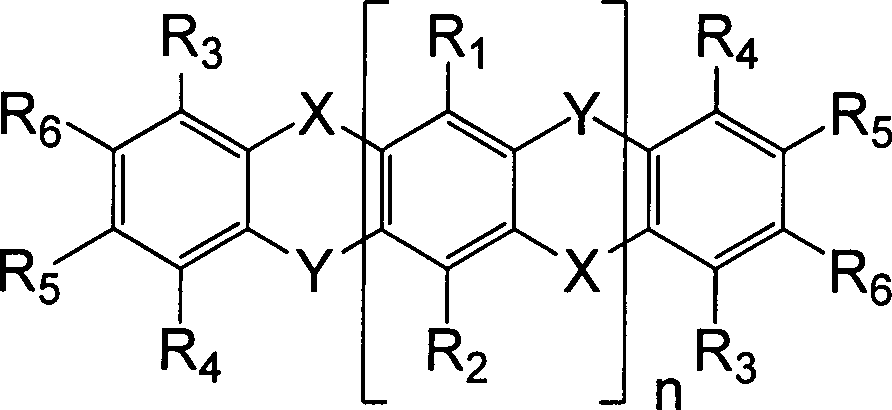


Die beschriebenen Verbindungen und deren Derivate werden vorzugsweise als Löchertransportmaterialien (HTM) in elektronischen Bauelementen benutzt. Die elektronischen Bauelemente können organische Solarzellen, organische Leuchtdioden, organische Dünnschichttransistoren, Dioden, Photodioden oder andere sein. Die Bauelemente können auch passive Bauteile wie z. B. Stromleitpfade, Stromsicherungen, Antennen und Widerstände sein. Es versteht sich, dass die Anwendung der (HTM) in anderen Halbleiterschichten möglich und nicht auf die hier beschriebenen Bauelemente begrenzt ist.The described compounds and their derivatives are preferably used as hole transport agents Rials (HTM) used in electronic components. The electronic components may be organic solar cells, organic light-emitting diodes, organic thin-film transistors, diodes, photodiodes or others. The components can also passive components such. B. Stromleitpfade, current fuses, antennas and resistors. It is understood that the application of (HTM) in other semiconductor layers is possible and not limited to the devices described herein.
Dotierte HTM-Schichten können in vielen verschiedenen Bauelementen eingesetzte werden, wobei es eine große Flexibilität zur Wahl der Materialien gibt, sobald die gewünschte Leitfähigkeit erreicht wird. Für spezielle Schichten, meistens aber nicht nur in undotierte Schichten, werden auch spezielle Energieniveaus erfordert, wie bei der injektion-Order-Extraktion von Ladungsträgern in intrinsischen photo-aktiven Schichten. In opto-elektronischen Bauelementen müssen die Schichten, die nur zum Ladungsträgertransport dienen, im wesentlich transparent sein.doped HTM layers can be used in many different components be used, it being a great flexibility to choose the materials, as soon as the desired conductivity is reached. For special layers, but mostly not only in undoped layers, are also special energy levels requires, as in the injection-order extraction of carriers in intrinsic photo-active layers. In opto-electronic Components need the layers that are just for cargo transport serve, be essentially transparent.
Die beschriebenen Verbindungen und deren Derivate können einzeln als Materialschicht verwendet werden, oder als Mischung mit anderen Materialien, die funktionelle Eigenschaften zur Schicht hinzufiügen, z. B. Mischungen mit anderen HTM.The described compounds and their derivatives can individually used as a material layer, or as a mixture with others Materials that add functional properties to the layer, z. B. mixtures with other HTM.
Vorzugsweise
werden die neuen Materialien mit einem p-Dotanden dotiert. Bevorzugte
p-Dotanden sind aus der
Die erfindungsgemäßen Materialien und deren Derivate werden bevorzugt in OLEDs in Löchertransportschichten (HTL) als eine dotierte Schicht verwendet. Es ist auch vorgesehen, dass eine undotierte Schicht als Zwischenschicht benutzt wird. Die Dioxa-dithia-pentacen-Derivate werden auch bevorzugt als Elektronenblocker oder als Excitonenblocker oder beides, Excitonen- und Elektronenblocker gleichzeitig, eingesetzt.The Inventive materials and their derivatives are preferred in OLEDs in hole transport layers (HTL) used as a doped layer. It is also envisaged that an undoped layer is used as the intermediate layer. The dioxa-dithia-pentacene derivatives are also preferred as electron blockers or as exciton blockers or both, exciton and electron blockers simultaneously.
Die
Dioxa-dithia-pentacen Derivate werden bevorzugt in organischen Solarzellen
eingesetzt, in dotierten Löchertransportschichten. Die
organischen Solarzellen können auch eine nicht dotierte
Schicht als Elektronen-, Loch- oder auch Excitonen-Blocker aufweisen.
Der Aufbau von organischen Solarzellen ist dem Fachmann bekannt,
siehe
Die Verbindungen zeigen eine geringe oder überhaupt keine Kristallinität. Somit sind diese Materialien besonders geeignet, um stabile Bauelemente herzustellen.The Compounds show little or no crystallinity. Thus, these materials are particularly suitable for stable components manufacture.
Wegen
der hohen Ladungsträgerbeweglichkeit werden die Materialien
bevorzugt auch in organischen Dünnschichttransistoren als
aktive Schicht eingesetzt. Die aktive Schicht kann auch dotierte
Bereiche enthalten, z. B. Injektionsschichten, ist aber im wesentlich
undotiert. Die organischen Dünnschichttransistoren und deren
Herstellung sind dem Fachmann bekannt, siehe z. B.
Es
ist weiterhin bevorzugt, dass die erfindungsgemäßen
Materialien und deren Derivate eine hohe Transparenz aufweisen,
was üblicherweise von der großen HOMO-LUMO Lücke
(band-Lücke) gegeben ist. Eine Bandlücke von mindestens
1 eV ist geeignet, bevorzugt ist eine Bandlücke von mindestens
1,5 eV, weiter bevorzugt ist eine Bandlücke von 2 eV. Dotierte
oder undotierte transparente Halbleiterschichten werden in opto-elektronischen
Bauelementen in nicht optisch aktiven Schichten verwendet, weil
die Absorption in diese Schichten deren Effizienz mindert. Dotierte
oder undotierte transparente Halbleiterschichten werden auch in völlig
oder im Wesentlichen transparenten Bauelementen benutzt, um so genannte
transparente Elektronik herzustellen. Transparente OLEDs sind z.
B. in
Die typische Struktur einer Standard-OLED ist dem Fachmann bekannt, sie kann wie folgt aussehen:
- 1. Träger, Substrat, z. B. Glas
- 2. Elektrode, löcherinjizierend (Anode = Pluspol), vorzugsweise transparent, z. B. Indium-Zinn-Oxid (ITO)
- 3. Löcherinjektionsschicht, z. B. CuPc (Kupfer-Phthalocyanin), oder Starburst-Derivate,
- 4. Löchertransportschicht, z. B. TPD (Triphenyldiamin und Derivate),
- 5. löcherseitige Blockschicht, um Exzitonendiffusion aus der Emissionsschicht zu verhindern und Ladungsträger-Leckage aus der Emissionsschicht zu verhindern, z. B. alpha-NPB (Bis-naphtyl-phenylamino-biphenyl),
- 6. lichtemittierende Schicht oder System von mehreren zur Lichtemission beitragenden Schichten, z. B. CBP (Carbazol-Derivate) mit Emitterbeimischung (z. B. phosphoreszenter Triplett-Emitter Iridium-tris-phenylpyridin Ir(ppy)3) oder Alq3 (Trisquinolinato-aluminium) gemischt mit Emittermolekülen (z. B. fluoreszenter Singlett Emitter Qumarin),
- 7. elektronenseitige Blockschicht, um Exzitonendiffusion aus der Emissionsschicht zu verhindern und Ladungsträger-Leckage aus der Emissionsschicht zu verhindern, z. B. BCP (Bathocuproine),
- 8. Elektronentransportschicht, z. B. Alq3 (Tris-quinolinato-aluminium),
- 9. Elektroneninjektionsschicht, z. B. anorganisches Lithiumfluorid (LiF),
- 10. Elektrode, meist ein Metall mit niedriger Austrittsarbeit, elektroneninjizierend (Kathode = Minuspol), z. B. Aluminium.
- 1st carrier, substrate, z. Glass
- 2nd electrode, hole injecting (anode = positive pole), preferably transparent, z. B. Indium Tin Oxide (ITO)
- 3. hole injection layer, z. CuPc (copper phthalocyanine), or starburst derivatives,
- 4. hole transport layer, z. TPD (triphenyldiamine and derivatives),
- 5. hole-side block layer to prevent exciton diffusion from the emission layer and to prevent charge carrier leakage from the emission layer, e.g. B. alpha-NPB (bis-naphthyl-phenylamino-biphenyl),
- 6. Light-emitting layer or system of several contributing to the light emission layers, eg. B. CBP (carbazole derivatives) with emitter addition (eg phosphorescent triplet emitter iridium-tris-phenylpyridine Ir (ppy) 3) or Alq3 (trisquinolinato-aluminum) mixed with emitter molecules (eg single singlet fluorescent emitter Qumarin) .
- 7. electron-side blocking layer to prevent exciton diffusion from the emission layer and to prevent charge carrier leakage from the emission layer, e.g. B. BCP (Bathocuproine),
- 8. Electron transport layer, z. Alq3 (Tris-quinolinato-aluminum),
- 9. Electron injection layer, z. As inorganic lithium fluoride (LiF),
- 10. electrode, usually a metal with low work function, electron-injecting (cathode = negative pole), z. As aluminum.
Es können natürlich Schichten weggelassen werden, oder eine Schicht (respektive ein Material) kann mehrere Eigenschaften übernehmen, z. B. können die Schichten 3 und 4, 4 und 5, 3–5 zusammengefasst werden, bzw. die Schichten 7 und 8, 8 und 9, und 7–9 zusammengefasst werden. Weiter Möglichkeiten sehen die Mischung der Substanz aus Schicht 9 in die Schicht 8 vor etc..It Of course, layers can be left out, or a layer (or a material) can take on several properties, z. For example, layers 3 and 4, 4 and 5, 3-5 or layers 7 and 8, 8 and 9, and 7-9 are summarized. Next options see the mixture of substance from layer 9 in the layer 8 before Etc..
Eine reflektierende Elektrode und organische Schichten werden normalerweise durch thermische Vakuumverdampfung auf einem Substrat abgeschieden. Die Elektrode kann auch gesputtert werden. Unter anderem können die organische Schichten aus Lösungsmitteln hergestellt werden, wie z. B. durch Spin-coating und Ink-jet-Drucken.A reflective electrode and organic layers become normal deposited by thermal vacuum evaporation on a substrate. The electrode can also be sputtered. Among other things can the organic layers made from solvents be such. B. by spin-coating and ink-jet printing.
Dieser
Aufbau beschreibt den nicht-invertierten (Anode auf dem Substrat),
substratseitig emittierenden (bottom-emission) Aufbau einer OLED.
Es gibt verschiedene Konzepte, vom Substrat weg emittierende OLEDs
zu beschreiben (siehe Referenzen in
Wenn
die Reihenfolge der Schichten invertiert wird (Kathode auf Substrat)
spricht man von invertierten OLEDs (siehe Referenzen in
Typischerweise
umfasst die organische Schichtanordnung einer OLED oder einer Solarzelle
mehrere übereinander angeordnete organische Schichten.
Innerhalb der organischen Schichtanordnung können auch ein
oder mehrere pn-Übergänge vorgesehen sein, wie
dieses für ge stapelte OLEDs bekannt ist (vgl.
In
Solarzellen und Photosensoren wird der pn-Übergang auch
benutzt, um gestapelte Heterojunctions zu verbinden und somit die
Spannung, die dieses Bauelement generiert, zu addieren (
Die Übergänge
werden auch benutzt, um eine verbesserte Injektion (Extraktion bei
Solarzellen) zu den Elektroden zu bekommen (
Zur
Verbesserung der energetischen Eigenschaften in einem organischen
elektronischen Bauelement wurde in dem Dokument
Um
den pn-Übergang zu stabilisieren, wird eine Schicht von
einem anderen Material als Zwischenschicht benutzt. Solche stabilisierten
pn-Übergänge sind z. B. in
Mit den erfindungsgemäßen Materialien können stabile Zwischenschichten bzw. dotierte Zwischenschichten zwischen den pn-Übergängen bereitgestellt werden, um stabile organische Halbleiterbauelemente herzustellen.With the materials of the invention can stable intermediate layers or doped intermediate layers between The pn junctions are provided to be stable produce organic semiconductor devices.
Es
ist bekannt dass ein solcher pn-Übergang sehr effizient
funktioniert, wenn beide Materialien vom p- und n-Typ dotiert sind
(
Ebenfalls ist es möglich, ein Material und eine Materialkombination herzustellen, um einen effizienten und stabilen, hauptsächlich thermisch stabilen pn-Übergang bereitzustellen.Also is it possible to have a material and a material combination to produce an efficient and stable, mainly provide thermally stable pn junction.
pn Übergänge werden in OLEDs auch charge generation layer oder auch connection unit genannt. pn Übergänge werden in organischen Solarzellen auch als recombination layer bezeichnet.pn transitions In OLEDs, charge generation layers or connections are also used called unit. pn transitions are in organic Solar cells also known as recombination layer.
Weitere Merkmale und Vorteile der Erfindung ergeben sich aus der folgenden detaillierten Beschreibung von Ausführungsbeispielen, die jedoch nicht beabsichtigt sind, um den Umfang der Erfindung in irgendeiner Weise zu begrenzen.Further Features and advantages of the invention will become apparent from the following detailed description of embodiments that however, are not intended to limit the scope of the invention in any way Way to limit.
BeispieleExamples
Synthesebeispiel 1:Synthetic Example 1:
5,12-Dioxa-7,14-dithia-pentacen5,12-dioxa-7,14-dithia-pentacene
Kalium-t-butanolat (2,78 g; 24,8 mmol) wurden unter Schutzgasatmosphäre in 30 ml wasserfreiem Dimethylformamid suspendiert. Die Suspension wurde auf 0°C gekühlt und 2-Mercaptophenol (1,96 g; 15,5 mmol) wurde in 30 ml wasserfreiem Dimethylformamid lang sam zugetropft. Nach Entfernen des Eisbades wurde die Reaktion weitere 30 min gerührt, bis sich eine viskose hellgelbe Lösung bildete. 1,2,4,5-Tetrafluorbenzen (0,93 g; 6,20 mmol) wurde zugegeben und die Mischung zwei Tage am Rückfluss erhitzt. Danach wurde das Dimethylformamid im Vakuum entfernt und der Rückstand in 30 ml Chloroform gelöst. Die organische Phase wurde dreimal mit 15 ml Wasser gewaschen und anschließend mit Natriumsulfat getrocknet. Das Lösungsmittel wurde im Vakuum entfernt und der Rückstand aus Chloroform/Methanol umkristallisiert. Es wurden 1,10 g (50%; 3,4 mmol)) als weißer Feststoff isoliert. Schmelzpunkt: 223°CPotassium t-butoxide (2.78 g, 24.8 mmol) were added under a protective gas atmosphere in 30 ml of anhydrous dimethylformamide suspended. The suspension was cooled to 0 ° C and 2-mercaptophenol (1.96 G; 15.5 mmol) was slowly sam in 30 ml of anhydrous dimethylformamide dropwise. After removal of the ice bath, the reaction became more Stirred for 30 min, until a viscous pale yellow solution formed. 1,2,4,5-tetrafluorobenzene (0.93 g, 6.20 mmol) was added and the mixture heated for two days at reflux. After that The dimethylformamide was removed in vacuo and the residue dissolved in 30 ml of chloroform. The organic phase was washed three times with 15 ml of water and then with Dried sodium sulfate. The solvent was in vacuo removed and the residue recrystallized from chloroform / methanol. There was added 1.10 g (50%, 3.4 mmol) as a white solid isolated. Melting point: 223 ° C
Synthesebeispiel 2:Synthetic Example 2:
5,9,16-trioxa-7,14,18-trithiaheptacentrioxa-7,14,18-5,9,16-trithiaheptacen
1. Stufe: Darstellung von Tetrabromphenoxathiin1st stage: Preparation of tetrabromophenoxathiin
10 g Phenoxathiin (49,9 mmol) werden in 250 ml Trifluoressigsäure suspendiert und vorsichtig mit 23,0 ml Brom (71,7 g, 449 mmol, 9 eq) versetzt. Die Mischung wird für 3 Tage bei Raumtemperatur gerührt und über das GCMS kontrolliert (THF als Laufmittel). Nach Beendigung der Reaktion wird die rötlich-braune Reaktionsmischung solange mit gesättigter Na2SO3-Lösung versetzt, bis sie sich vollständig entfärbt hat. Der ausgefallene Feststoff wird abgesaugt und mit Na2SO3-Lösung, Wasser und zuletzt Methanol gewaschen und getrocknet. Der leicht bräunliche Feststoff wird aus Toluol umkristallisiert und man erhält 18,0 g Produkt in Form eines rein-weißen Feststoff (GCMS 98% rein).10 g of phenoxathiin (49.9 mmol) are suspended in 250 ml of trifluoroacetic acid and cautiously admixed with 23.0 ml of bromine (71.7 g, 449 mmol, 9 eq). The mixture is stirred for 3 days at room temperature and monitored by GCMS (THF as eluent). After completion of the reaction, the reddish-brown reaction mixture is treated with saturated Na 2 SO 3 solution until it has completely decolorized. The precipitated solid is filtered off with suction and washed with Na 2 SO 3 solution, water and finally methanol and dried. The slightly brownish solid is recrystallized from toluene to give 18.0 g of product as a pure white solid (GCMS 98% pure).
2. Stufe: Umsetzung von Tetrabromphenoxathiin2nd stage: reaction of tetrabromophenoxathiin
0,61 g 2-Mercaptophenol (4,8 mmol, 2,5 eq) werden unter Argon in 12 ml DMF gelöst und zu einer Suspension von 1,34 g Kaliumcarbonat (9,7 mmol, 10 eq) in 12 ml DMF zugetropft. Die Mischung wird für 30 min gerührt und anschließend werden 1,00 g Tetrabromphenoxathiin (1,9 mmol) zugeben. Die Mischung wird anschließend für mindestens 4 Tage unter Rückfluss erhitzt (Reaktionskontrolle über HPLC-MS C18). Nach Beendigung der Reaktion wird das DMF unter reduziertem Druck entfernt und der Rückstand in 100 ml Chloroform aufgenommen und mit Wasser, 1 N Natriumhydrogencarbonat-Lösung und noch einmal mit Wasser ausgerührt (je 50 ml). Der zurückbleibende, ungelöste Feststoff wird abfiltriert und die organische Phase getrocknet und eingeengt. Der ungelöste Feststoff (4,2 g) wird in 2 L Toluol unter Rückfluß gelöst, filtriert und auf ca. 250 ml eingeengt. Aus der Mutterlauge fallen 3,0 g Produkt in Form rein-weißer Kristalle (95% laut HPLC) aus. Aus der organischen Phase erhält man durch zweifache Kristallisation aus Toluol zusätzlich 1,0 g Produkt als gelblichen Feststoff (ca. 95% laut HPLC). Schmelzpunkt: 268°C0.61 g of 2-mercaptophenol (4.8 mmol, 2.5 eq) are dissolved under argon in 12 ml of DMF and added dropwise to a suspension of 1.34 g of potassium carbonate (9.7 mmol, 10 eq) in 12 ml of DMF , The mixture is stirred for 30 min and then 1.00 g of tetrabromophenoxathiin (1.9 mmol) are added. The mixture is then refluxed for at least 4 days (reaction control via HPLC-MS C18). After completion of the reaction, the DMF is removed under reduced pressure and the residue taken up in 100 ml of chloroform and washed with water, 1 N sodium bicarbonate solution and once more with water stirred (50 ml each). The remaining, undissolved solid is filtered off and the organic phase is dried and concentrated. The undissolved solid (4.2 g) is dissolved in 2 L toluene under reflux, filtered and concentrated to about 250 ml. From the mother liquor, 3.0 g of product precipitate in the form of pure white crystals (95% according to HPLC). From the organic phase is obtained by double crystallization from toluene additionally 1.0 g of product as a yellowish solid (about 95% by HPLC). Melting point: 268 ° C
Synthesebeispiel 3:Synthesis Example 3:
3,10-Dimethoxy-5,12-dioxa-7,14-dithiapentacene3,10-dimethoxy-5,12-dioxa-7,14-dithiapentacene
1. Stufe: Methylierung von 6-Hydroxy-1,3-benzoxanthiol-2-on(Thioxolon)1st stage: Methylation of 6-hydroxy-1,3-benzoxanthiol-2-one (thioxolone)
6,50 g (38,7 mmol) 6-Hydroxy-1,3-benzoxanthiol-2-on werden in 130 mL DMF gelöst und mit 4,27 g (30,9 mmol, 0,8 eq.) Kaliumcarbonat versetzt. Zu der Reaktionsmischung werden 3,10 ml (7,09 g, 50,3 mmol, 1,3 eq.) Methyliodid vorsichtig zugetropft. Die Reaktion wird über Nacht gerührt, auf Eiswasser gegeben und anschließend mit Chloroform ausgeschüttelt. Die organische Phase wird über Natriumsulfat getrocknet und eingeengt. Der feste Rückstand wird in Methanol aufgenommen, gerührt und filtriert. Der trockene, reinweiße Feststoff (GCMS-Reinheit 100%, M = 182) fällt in einer Ausbeute von 4,60 g (65% d. Th.) an.6.50 g (38.7 mmol) of 6-hydroxy-1,3-benzoxanthiol-2-one are dissolved in 130 ml DMF and with 4.27 g (30.9 mmol, 0.8 eq.) Of potassium carbonate added. To the reaction mixture is added 3.10 ml (7.09 g, 50.3 mmol, 1.3 eq.). Methyl iodide is carefully added dropwise. The reaction is over Stirred overnight, added to ice water and then shaken out with chloroform. The organic phase is over Dried sodium sulfate and concentrated. The solid residue is taken up in methanol, stirred and filtered. Of the dry, pure white solid (GCMS purity 100%, M = 182) is obtained in a yield of 4.60 g (65% of theory).
2. Stufe: Spaltung des Heterozyklus2nd stage: cleavage of the heterocycle
4,50 g (24,8 mmol) 6-Methoxy-1,3-benzoxathiol-2-on werden in 56 ml Methanol suspendiert und mit 4,40 g (66,4 mmol) 85%igem Kaliumhydroxid versetzt, die zuvor in 11 mL Methanol und 17 mL Wasser gelöst worden sind. Die Suspension löst sich unter Gelbfärbung auf und wird für ca. 10 min gerührt (DC-Kontrolle). Nach Beendigung der Reaktion wird die Reaktionsmischung vorsichtig mit 1 N wässriger Salzsäure auf pH 1 angesäuert, das Methanol unter reduziertem Druck entfernt und der Rückstand zweimal mit Ethylacetat ausgeschüttelt. Die organischen Phasen werden vereinigt und je zweimal mit Wasser, gesättigter Natriumchloridlösung und noch einmal mit Wasser gewaschen. Nach Trocknen mit Natriumsulfat und Entfernen des Lösungsmittels unter reduziertem Druck, fallen 3,55 g (92%) 5-Methoxy-2-mercaptophenol als leicht gelbliche Flüssigkeit an. Das Rohprodukt (GCMS 100%, M = 156) wird ohne weitere Aufreinigung weiter eingesetzt.4.50 g (24.8 mmol) of 6-methoxy-1,3-benzoxathiol-2-one are dissolved in 56 ml of methanol 4.40 g (66.4 mmol) of 85% potassium hydroxide are added, previously dissolved in 11 mL of methanol and 17 mL of water are. The suspension dissolves under yellowing and is stirred for about 10 min (TLC control). To Termination of the reaction is careful with the reaction mixture 1 N aqueous hydrochloric acid acidified to pH 1, the methanol removed under reduced pressure and the residue shaken twice with ethyl acetate. The organic ones Phases are combined and twice each with water, more saturated Sodium chloride solution and washed once more with water. After drying with sodium sulfate and removing the solvent under reduced pressure, 3.55 g (92%) of 5-methoxy-2-mercaptophenol as a slightly yellowish liquid. The crude product (GCMS 100%, M = 156) is used without further purification.
3. Stufe: Umsetzung mit 1,2,4,5-Tetrafluorbenzol3rd stage: reaction with 1,2,4,5-tetrafluorobenzene
0,72 g (6,40 mmol) trockenes Kalium-tert-butylat werden in 10 mL trockenem DMF suspendiert. Zu der Suspension werden vorsichtig unter Eiskühlung 0,50 g (3,2 mmol) 5-Methoxy-2-mercaptophenol in 10 ml trockenem DMF zugegeben. Die Mischung wird für 30 min bei RT gerührt und anschließend mit 0,14 mL (0,19 g, 1,3 mmol) Tetrafluorbenzol versetzt. Die Reaktionsmischung wird für 3 Tage bei 100°C gerührt. Anschließend wird sie mit Chloroform und Wasser ausgeschüttelt. Die organische Phase wird mit Natriumsulfat getrocknet und eingeengt. 1,66 g Rohprodukt fällt als leicht gelblicher Feststoff an (GCMS: 79%, M = 382). Das Produkt wird aus Chloroform auskristallisiert und anschließend die Mutterlauge mit Methanol nachgefällt. Man erhält 620 mg reinweißes Produkt (GCMS: 100%). Aus 500 mg sublimieren 230 mg (entspricht 57% d. Theorie). Schmelzpunkt: 230°C0.72 g (6.40 mmol) of dry potassium tert-butoxide are dissolved in 10 mL of dry DMF suspended. To the suspension, carefully with ice cooling 0.50 g (3.2 mmol) of 5-methoxy-2-mercaptophenol in 10 ml of dry DMF added. The mixture is stirred for 30 min at RT and then with 0.14 mL (0.19 g, 1.3 mmol) of tetrafluorobenzene added. The reaction mixture is kept at 100 ° C for 3 days touched. Subsequently, she is treated with chloroform and shaken out water. The organic phase is with Dried sodium sulfate and concentrated. 1.66 g of crude product falls as a slightly yellowish solid (GCMS: 79%, M = 382). The product will crystallized from chloroform and then the mother liquor replenished with methanol. This gives 620 mg pure white Product (GCMS: 100%). From 500 mg sublime 230 mg (equivalent 57% d. Theory). Melting point: 230 ° C
Leitfähigkeitsmessungen:Conductivity measurements:
Alle verwendeten Materialien wurden zusätzlich durch Gradientensublimation gereinigt.All Materials used were additionally by gradient sublimation cleaned.
5,12-Dioxa-7,14-dithia-pentacen wurde zusammen mit 10 Mol% 2-(6-Dicyanomethylen-1,3,4,5,7,8-hexafluor-6H-naphthalen-2-yliden)-malononitril coverdampft. Als Leitfähigkeit einer dotierten 50 nm Schicht wurden 1,9·10–5 S/cm gemessen. 5,12-Dioxa-7,14-dithiapentacen wurde auch als Mischschicht zusammen mit 10 Mol% 2,2',2''-(Cyclopropan-1,2,3-triyliden)tris(2-(2,3,5,6-tetrafluor-4-(trifluormethyl)phenyl)-acetonitril) verdampft, so dass die Endschicht 50 nm dick war. Als Leitfähigkeit wurden 3·10–7 S/cm gemessen. Eine dotierte, 50 nm dicke Schicht 5,9,16-Trioxa-7,14,18-trithiaheptacen wurde mit 10 Mol% 2-(6-Dicyanomethylen-1,3,4,5,7,8-hexafluor-6H-naphthalen-2-yliden)-malononitril coverdampft. Als Leitfähigkeit wurden 1,1·10–3 S/cm gemessen. 3,10-Dimethoxy-5,12-dioxa-7,14-dithiapentacen wurde zusammen mit 10 Mol% mit demselben Dotanden, wie im vorigen Beispiel coverdampft (Dicke 50 nm). Als Leitfähigkeit wurden 1,2·10–5 S/cm gemessen. Besonders gute Eigenschaften, die nicht auf die Beispiele begrenzt sind, wie Leistungseffizienz und thermische Stabilität, wurden mit p-Dotierung mit den folgenden p-Dotanden erreicht: 2,2-(Perfluornaphthalen-2,6-diyliden)dimalononitril; 2,2'-(2,5-Dibrom-3,6-difluorcyclohexa-2,5-dien-1,4-diyliden)dimalononitril; (2E,2'E,2''E)-2,2',2''-(Cyclopropan-1,2,3-triyliden)tris(2-(2,6-dichlor-3,5-difluor-4-(trifluormethyl)phenyl)acetonitril); (2E,2'E,2''E)-2,2',2''-(cyclopropane-1,2,3-triylidene)tris(2-(4-cyanoperfluorophenyl)-acetonitril). Alle Messungen wurden bei Raumtemperatur durchgeführt. Die Leitfähigkeitmessungen können in Vakuum, in einer Schutzgasatmosphäre oder in versiegelten Proben durchgeführt werden, mit keinen oder nur sehr geringen Abweichungen der Messwerte.5,12-Dioxa-7,14-dithia-pentacene was used along with 10 mol% of 2- (6-dicyanomethylene-1,3,4,5,7,8-hexafluoro-6H-naphthalen-2-ylidene) -malononitrile co-evaporated. As the conductivity of a doped 50 nm layer, 1.9 × 10 -5 S / cm was measured. 5,12-Dioxa-7,14-dithiapentacene was also used as a mixed layer together with 10 mol% 2,2 ', 2''- (cyclopropane-1,2,3-triylidene) tris (2- (2,3,5 , 6-tetrafluoro-4- (trifluoromethyl) phenyl) -acetonitrile), so that the final layer was 50 nm thick. The conductivity measured was 3 × 10 -7 S / cm. A doped, 50 nm thick layer of 5,9,16-trioxa-7,14,18-trithiaheptacene was mixed with 10 mol% 2- (6-dicyanomethylene-1,3,4,5,7,8-hexafluoro-6H- naphthalene-2-ylidene) -malononitrile co-evaporates. As conductivity 1.1 × 10 -3 S / cm were measured. 3,10-Dimethoxy-5,12-dioxa-7,14-dithiapentacene was co-evaporated together with 10 mol% with the same dopant as in the previous example (thickness 50 nm). The conductivity measured was 1.2 × 10 -5 S / cm. Particularly good properties, which are not limited to the examples, such as power efficiency and thermal stability, were achieved with p-doping with the following p-dopants: 2,2- (perfluoronaphthalene-2,6-diylidene) dimalononitrile; 2,2 '- (2,5-dibromo-3,6-difluorcyclohexa-2,5-dien-1,4-diylidene) dimalononitril; (2E, 2'E, 2''E) -2,2 ', 2''- (cyclopropane-1,2,3-triyliden) tris (2- (2,6-dichloro-3,5-difluoro- 4- (trifluoromethyl) phe nyl) acetonitrile); (2E, 2'E, 2''E) -2,2 ', 2''- (cyclopropane-1,2,3-triylidene) tris (2- (4-cyanoperfluorophenyl) acetonitrile). All measurements were carried out at room temperature. The conductivity measurements can be carried out in vacuum, in an inert gas atmosphere or in sealed samples, with no or only very small deviations of the measured values.
Synthesebeispiel 4Synthesis Example 4
6,6'-Bis(5,12-Dioxa-7,14-dithia-pentacen)6,6'-bis (5,12-dioxa-7,14-dithia-pentacene)
5,30 g 2-Mercaptophenol (42,0 mmol, 5 eq) werden unter Argon in 100 ml DMF gelöst und zu einer Suspension von 11,6 g Kaliumcarbonat (84,0 mmol, 10 eq) in 100 ml DMF zugetropft. Die Mischung wird für 30 min gerührt und anschließend werden 2,50 g 4,4'H- Octafluorbiphenyl (8,5 mmol) zugeben. Die Mischung wird anschließend für 6 Tage unter Rückfluss erhitzt (Reaktionskontrolle über HPLC-MS C18). Am 4. Tag wird ein weiteres Äquivalent Mercaptophenol zugegeben. Nach Beendigung der Reaktion wird das DMF unter reduziertem Druck entfernt und der Rückstand in 100 ml Chloroform aufgenommen und mit Wasser, 1 N Natriumhydrogencarbonat-Lösung und noch einmal mit Wasser ausgerührt (je 50 ml). Die organische Phase wird getrocknet und eingeengt. Der feste Rückstand wird aus Chloroform und Methanol ausgefällt und aus Isopropanol umkristallisiert.5.30 g 2-Mercaptophenol (42.0 mmol, 5 eq) is dissolved under argon in 100 ml Dissolved DMF and a suspension of 11.6 g of potassium carbonate (84.0 mmol, 10 eq) was added dropwise in 100 ml of DMF. The mixture is for 30 stirred and then 2.50 g of 4,4'H-octafluorobiphenyl Add (8.5 mmol). The mixture is then for Heated under reflux for 6 days (reaction control over HPLC-MS C18). On the 4th day, another equivalent is mercaptophenol added. After completion of the reaction, the DMF is reduced Removed pressure and the residue taken up in 100 ml of chloroform and with water, 1 N sodium bicarbonate solution and once more with water (50 ml each). The organic Phase is dried and concentrated. The solid residue is precipitated from chloroform and methanol and from isopropanol recrystallized.
Synthesebeispiel 5Synthesis Example 5
N,N,N',N'-Tetraphenyl-5,12-dioxa-7,14-dithiapentacen-6,13-diaminN, N, N ', N'-tetraphenyl-5,12-dioxa-7,14-dithiapentacen-6,13-diamine
Stufe 1: Bisaminierung von HexafluorbenzolStep 1: Bisamination of hexafluorobenzene
Mit Hexan gewaschenes Natriumhydrid (2,80 g, 118 mmol) wird unter Argon-Atmosphäre in trockenem Dimethylformamid (200 mL) suspendiert. Zur Suspension wird eine Lösung von Diphenylamin (20,0 g, 118 mmol) in Dimethylformamid (200 mL) zugetropft, wobei Wasserstoff entsteht (!). Die Suspension wird für 30 min gerührt und anschließend Hexafluorbenzol (10,0 g, 54,0 mmol, 6,2 mL) über eine Spritze zugegeben. Die Reaktionsmischung wird über Nacht bei 100°C gerührt. Anschließend wird das Lösungsmittel am Rotationsverdampfer entfernt. Der Rückstand wird in Chloroform aufgenommen und mehrfach mit Wasser gewaschen. Die organische Phase wird über MgSO4 getrocknet, filtriert und eingeengt. Der feste Rückstand wird in Methanol (2 × 25 ml) ausgerührt und das Produkt als rein weißer Feststoff abgesaugt (GC-MS 100%). Ausbeute: 20,9 g.With Hexane washed sodium hydride (2.80 g, 118 mmol) is added under argon atmosphere suspended in dry dimethylformamide (200 mL). To the suspension a solution of diphenylamine (20.0 g, 118 mmol) in Dimethylformamide (200 mL) was added dropwise to give hydrogen (!). The suspension is stirred for 30 minutes and then hexafluorobenzene (10.0 g, 54.0 mmol, 6.2 mL) a syringe added. The reaction mixture is over Stirred at 100 ° C overnight. Subsequently the solvent is removed on a rotary evaporator. The residue is taken up in chloroform and repeatedly washed with water. The organic phase is over MgSO4 dried, filtered and concentrated. The solid residue is stirred in methanol (2 × 25 ml) and the Product filtered off with suction as a pure white solid (GC-MS 100%). Yield: 20.9 g.
Stufe 2: Aromatische Substitution mit 2-MercaptophenolStep 2: Aromatic substitution with 2-mercaptophenol
Kalium-t-butylat (1,62 g, 14,5 mmol) wird in trockenem Dimethylformamid (30 ml) unter Argon-Atmosphäre suspendiert. Unter Eiskühlung wird eine Lösung von 2-Mercaptophenol (0,91 g, 7,20 mmol) in trockenem Dimethylformamid (30 ml) langsam hinzugetropft. Das Eisbad wird entfernt und die Reaktionsmischung solange gerührt, bis sich eine leicht gelbliche Suspension gebildet hat (ca. 30 min). Das 1,4-Bis(diphenylamin)tetrafluorbenzol wird in Substanz hinzugeben und die Reaktion für 3 Tage unter Rückfluß erhitzt (DC-Kontrolle). Das Lösungsmittel wird am Rotationsverdampfer entfernt und der Rückstand in Chloroform aufgenommen und mit Wasser mehrfach ausgeschüttelt. Die organische Phase wird über MgSO4 getrocknet, filtriert und eingeengt. Die wässrige Phase wird mit Calciumchlorid versetzt. Das Rohprodukt wird aus Chloroform/Methanol ausgefällt und man erhält 1,28 g (67% d. Theorie) in Form eines leicht gelblichen Feststoffs vor. HPLC-MS (gemessen in Pyridin) zeigt eine Reinheit von 95%. Smp. 314°C.Potassium t-butoxide (1.62 g, 14.5 mmol) is dissolved in dry dimethylformamide (30 ml) Argon atmosphere suspended. Under ice cooling a solution of 2-mercaptophenol (0.91 g, 7.20 mmol) is added in dry dimethylformamide (30 ml) is added slowly dropwise. The Ice bath is removed and the reaction mixture is stirred while until a slightly yellowish suspension has formed (about 30 minutes). The 1,4-bis (diphenylamine) tetrafluorobenzene is added in bulk and refluxing the reaction for 3 days (TLC). The solvent is on a rotary evaporator removed and the residue taken up in chloroform and Shaken out several times with water. The organic phase is dried over MgSO4, filtered and concentrated. The aqueous phase is treated with calcium chloride. The crude product is precipitated from chloroform / methanol and obtained 1.28 g (67% of theory) in the form of a slightly yellowish solid in front. HPLC-MS (measured in pyridine) shows a purity of 95%. Mp. 314 ° C.
Synthesewege für weitere Verbindungen:Synthetic pathways for other compounds:
Triangulare Derivate: 5,11,17-Trioxa-6,12,18-trithia-trinaphthylenTriangular derivatives: 5,11,17-trioxa-6,12,18-trithia-trinaphthylene
Diese
chemische Verbindung läßt sich in zwei Stufen
synthetisieren. Als Ausgangsverbindung kann hier das kommerziell
verfügbare 1,3,5-Tribrombenzol dienen, welches sich in
einer Cu-(I)-vermittelten Reaktion mit Phenol zum Tr-ether umsetzen
lässt. Dieselbe Reaktion wurde von v. Koten beschrieben
(
In
Anlehnung an die Synthese einfacher Phenoxathiine (
Durch die Verwendung funktionalisierter Phenole im ersten Schritt läßt sich die Peripherie der Zielverbindungen entsprechend modifizieren.By the use of functionalized phenols in the first step leaves modify the periphery of the target compounds accordingly.
Lineare Derivate: Modifikation der Positionen 6 und 13 im Grundkörper von 5,12-Dioxa-7,14-dithia-pentacenLinear derivatives: modification of positions 6 and 13 in the main body of 5,12-dioxa-7,14-dithia-pentacene
Aufgrund der Donoreigenschaften der Heteroatome lassen sich die Positionen 6 und 13 im Sinne einer ortho-Lithiierung in vielfältiger Weise modifizieren. Eine andere Art der Modifizierung wurde bereits am Synthesebeispiel von N,N,N',N'-Tetraphenyl-5,12-dioxa-7,14-dithiapentacene-6,13-diamine gezeigt.by virtue of The donor properties of the heteroatoms allow the positions 6 and 13 in the sense of ortho-lithiation in diverse Modify way. Another type of modification has already been made Synthesis example of N, N, N ', N'-tetraphenyl-5,12-dioxa-7,14-dithiapentacene-6,13-diamine shown.
Lineare Derivate: Modifikation der peripheren Positionen 1, 2, 3 oder 4 bzw. 8, 9, 10 oder 11 im Grundkörper von 5,12-Dioxa-7,14-dithia-pentacenLinear derivatives: modification of the peripheral Positions 1, 2, 3 or 4 or 8, 9, 10 or 11 in the main body of 5,12-dioxa-7,14-dithia-pentacene
Hier bieten sich ein- oder mehrfach halogen-substituierte Phenole (kommerziell erhältlich) an, die sich in einem ersten Schritt mittels gängiger ÜM-vermittelter Kupplungsmethoden in Aryl- oder Heteroarylderivate überführen lassen. In einem weiteren Schritt kann dann ebenfalls durch ortho-Metallierung zur Phenolfunktion unter Verwendung von elementarem Schwefel eine Mercapto-Gruppe eingeführt werden. Hier ist evtl. eine Trennung von Regioisomeren vorzunehmen.Here offer one or more halogen-substituted phenols (commercially available), which in a first step using common ÜM-mediated coupling methods in Aryl or heteroaryl derivatives can be converted. In a further step can then also by ortho-metallation for phenol functionality using elemental sulfur Mercapto group are introduced. Here is possibly a separation of regioisomers.
Diese funktionalisierten Mercaptophenole lassen sich in analogen Reaktionen zu dem oben beschriebenen Grundkörper umsetzen.These functionalized mercaptophenols can be resolved in analogous reactions to implement the basic body described above.
Die in der Beschreibung und in den Ansprüchen offenbarten Merkmale können sowohl einzeln als auch in beliebiger Kombination zur Verwirklichung der Erfindung in ihren verschiedenen Ausführungsformen wesentlich sein.The features disclosed in the specification and in the claims can be used individually or in any combination to the realization of the invention in its various embodiments essential be.
ZITATE ENTHALTEN IN DER BESCHREIBUNGQUOTES INCLUDE IN THE DESCRIPTION
Diese Liste der vom Anmelder aufgeführten Dokumente wurde automatisiert erzeugt und ist ausschließlich zur besseren Information des Lesers aufgenommen. Die Liste ist nicht Bestandteil der deutschen Patent- bzw. Gebrauchsmusteranmeldung. Das DPMA übernimmt keinerlei Haftung für etwaige Fehler oder Auslassungen.This list The documents listed by the applicant have been automated generated and is solely for better information recorded by the reader. The list is not part of the German Patent or utility model application. The DPMA takes over no liability for any errors or omissions.
Zitierte PatentliteraturCited patent literature
- - US 4769292 [0004] - US 4769292 [0004]
- - US 7074500 [0004] US 7074500 [0004]
- - US 20050110009 [0005] US 20050110009 [0005]
- - WO 2007/118799 A [0026] WO 2007/118799 A [0026]
- - JP 2002124384 A2 [0026] - JP 2002124384 A2 [0026]
- - US 2003099865 A [0026] - US 2003099865 A [0026]
- - US 6242115 B1 [0027] US 6242115 B1 [0027]
- - US 10/792133 [0038] - US 10/792133 [0038]
- - US 61/107826 [0038] US 61/107826 [0038]
- - US 11/047972 [0038] US 11/047972 [0038]
- - EP 07/00208 [0038] - EP 07/00208 [0038]
- - EP 1861886 [0040] - EP 1861886 [0040]
- - EP 1859494 [0040] - EP 1859494 [0040]
- - US 2006202196 [0042] US 2006202196 [0042]
- - US 20060033115 [0043] US 20060033115 [0043]
- - US 20060284170 [0043] US 20060284170 [0043]
- - DE 10215210 [0047] - DE 10215210 [0047]
- - DE 10135513 [0048] - DE 10135513 [0048]
- - EP 1478025 A2 [0049] - EP 1478025 A2 [0049]
- - US 2006027834 A [0050] US 2006027834 A [0050]
- - EP 1808910 [0051] EP 1808910 [0051]
- - WO 2005/109542 A1 [0052] WO 2005/109542 A1 [0052]
- - US 2006040132 A [0053] US 2006040132 A [0053]
- - EP 1804308 [0055] - EP 1804308 [0055]
- - EP 1804309 [0055] EP 1804309 [0055]
Zitierte Nicht-PatentliteraturCited non-patent literature
- - N. Sato et al., J.. Chem. Soc. Faraday Trans. 2, 77, 1621 (1981) [0021] Sato et al., J. Chem. Soc. Faraday Trans. 2, 77, 1621 (1981) [0021]
- - B. W. Andrade et al., Org. Electron. 6, 11 (2005) [0023] - BW Andrade et al., Org. Electron. 6, 11 (2005) [0023]
- - J. Amer. Chem. Soc. 127, (2005), 7227 [0023] - J. Amer. Chem. Soc. 127, (2005), 7227 [0023]
- - B. W. Andrade, Org. Electron. 6, 11 (2005) and Refs. 25–28 therein [0024] - BW Andrade, Org. Electron. 6, 11 (2005) and Refs. 25-28 therein [0024]
- - A. J. Bard, L. R. Faulkner, „Electrochemical Methods: Fundamentals and Applications”, Wiley, 2. Ausgabe 2000 [0024] - AJ Bard, LR Faulkner, "Electrochemical Methods: Fundamentals and Applications", Wiley, 2nd Edition 2000 [0024]
- - N. G. Connelly et al., Chem. Rev. 96, 877 (1996) [0024] Nelly Connelly et al., Chem. Rev. 96, 877 (1996) [0024]
- - G. van Koten et al., Tetrahedron Letters, 48 (2007), 7366–7370 [0070] Van Koten et al., Tetrahedron Letters, 48 (2007), 7366-7370 [0070]
- - Eric E. Borns et al., J. Heterocyclic Chem., 35, 699–706, 1998 [0071] Eric E. Borns et al., J. Heterocyclic Chem., 35, 699-706, 1998. [0071]
Claims (9)


Priority Applications (6)
| Application Number | Priority Date | Filing Date | Title |
|---|---|---|---|
| DE102008061843.8A DE102008061843B4 (en) | 2008-12-15 | 2008-12-15 | Heterocyclic compounds and their use in electronic and optoelectronic devices |
| US13/139,658 US9062064B2 (en) | 2008-12-15 | 2009-12-14 | Heterocyclic compounds and the use thereof in electronic and optoelectronic components |
| CN200980156831.5A CN102317406B (en) | 2008-12-15 | 2009-12-14 | Heterocyclic compound and the application in electronics and optoelectronic component thereof |
| KR1020117016623A KR101730934B1 (en) | 2008-12-15 | 2009-12-14 | Heterocyclic compounds and the use thereof in electronic and optoelectronic components |
| JP2011539896A JP5706829B2 (en) | 2008-12-15 | 2009-12-14 | Heterocyclic compounds and their use in electronic and optoelectronic devices |
| PCT/DE2009/001744 WO2010075836A2 (en) | 2008-12-15 | 2009-12-14 | Heterocyclic compounds and the use thereof in electronic and optoelectronic components |
Applications Claiming Priority (1)
| Application Number | Priority Date | Filing Date | Title |
|---|---|---|---|
| DE102008061843.8A DE102008061843B4 (en) | 2008-12-15 | 2008-12-15 | Heterocyclic compounds and their use in electronic and optoelectronic devices |
Publications (2)
| Publication Number | Publication Date |
|---|---|
| DE102008061843A1 true DE102008061843A1 (en) | 2010-06-17 |
| DE102008061843B4 DE102008061843B4 (en) | 2018-01-18 |
Family
ID=42100908
Family Applications (1)
| Application Number | Title | Priority Date | Filing Date |
|---|---|---|---|
| DE102008061843.8A Active DE102008061843B4 (en) | 2008-12-15 | 2008-12-15 | Heterocyclic compounds and their use in electronic and optoelectronic devices |
Country Status (6)
| Country | Link |
|---|---|
| US (1) | US9062064B2 (en) |
| JP (1) | JP5706829B2 (en) |
| KR (1) | KR101730934B1 (en) |
| CN (1) | CN102317406B (en) |
| DE (1) | DE102008061843B4 (en) |
| WO (1) | WO2010075836A2 (en) |
Families Citing this family (29)
| Publication number | Priority date | Publication date | Assignee | Title |
|---|---|---|---|---|
| KR101147428B1 (en) | 2009-02-09 | 2012-05-23 | 삼성모바일디스플레이주식회사 | Organic light emitting diode display |
| DE102010023620B4 (en) * | 2010-06-14 | 2016-09-15 | Novaled Ag | Organic, bottom-emitting device |
| CN102971883B (en) | 2010-06-14 | 2016-01-20 | 诺瓦莱德公开股份有限公司 | Organic luminescent device |
| WO2012166101A1 (en) * | 2011-05-27 | 2012-12-06 | Universal Display Corporation | Oled having multi-component emissivie layer |
| CN103620807B (en) * | 2011-06-21 | 2017-02-15 | 科迪华公司 | Materials and methods for OLED microcavities and buffer layers |
| JP6139552B2 (en) * | 2011-12-06 | 2017-05-31 | ノヴァレッド ゲーエムベーハー | ORGANIC LIGHT-EMITTING ELEMENT AND MANUFACTURING METHOD |
| DE102012207151A1 (en) | 2012-04-30 | 2013-10-31 | Osram Opto Semiconductors Gmbh | ORGANIC LIGHT-EMITTING COMPONENT AND METHOD FOR PRODUCING AN ORGANIC LIGHT-EMITTING COMPONENT |
| TWI668893B (en) * | 2012-05-31 | 2019-08-11 | 樂金顯示科技股份有限公司 | Organic electroluminescent device |
| JP5403179B1 (en) * | 2013-05-22 | 2014-01-29 | コニカミノルタ株式会社 | Charge transfer thin film |
| US9991453B2 (en) * | 2013-05-22 | 2018-06-05 | Konica Minolta, Inc. | Electronic device, organic electroluminescent element, organic thin-film solar cell, and dye-sensitized solar cell |
| CN104183736A (en) * | 2013-05-23 | 2014-12-03 | 海洋王照明科技股份有限公司 | Organic light emitting device and manufacturing method thereof |
| GB201310854D0 (en) * | 2013-06-18 | 2013-07-31 | Isis Innovation | Photoactive layer production process |
| JP2015155381A (en) * | 2014-02-19 | 2015-08-27 | 旭硝子株式会社 | Fluorine-containing aromatic compounds and production methods thereof |
| US9331299B2 (en) * | 2014-04-11 | 2016-05-03 | Universal Display Corporation | Efficient white organic light emitting diodes with high color quality |
| KR102294413B1 (en) | 2014-11-18 | 2021-08-27 | 삼성디스플레이 주식회사 | Organice light emitting diode display |
| EP3034489A1 (en) | 2014-12-16 | 2016-06-22 | Novaled GmbH | Substituted 1,2,3-triylidenetris(cyanomethanylylidene)) cyclopropanes for VTE, electronic devices and semiconducting materials using them |
| TWI599556B (en) * | 2015-07-03 | 2017-09-21 | 友達光電股份有限公司 | Organic emitting device |
| CN108496260B (en) | 2015-10-26 | 2020-05-19 | Oti照明公司 | Method for patterning a surface overlayer and device comprising a patterned overlayer |
| US11581487B2 (en) | 2017-04-26 | 2023-02-14 | Oti Lumionics Inc. | Patterned conductive coating for surface of an opto-electronic device |
| JP7264488B2 (en) | 2017-05-17 | 2023-04-25 | オーティーアイ ルミオニクス インコーポレーテッド | Methods and devices containing conductive coatings for selectively depositing conductive coatings over patterned coatings |
| US11751415B2 (en) | 2018-02-02 | 2023-09-05 | Oti Lumionics Inc. | Materials for forming a nucleation-inhibiting coating and devices incorporating same |
| WO2020178804A1 (en) | 2019-03-07 | 2020-09-10 | Oti Lumionics Inc. | Materials for forming a nucleation-inhibiting coating and devices incorporating same |
| CN110098345B (en) * | 2019-04-17 | 2020-11-06 | 深圳市华星光电半导体显示技术有限公司 | Organic light emitting diode display and method of manufacturing the same |
| US11832473B2 (en) | 2019-06-26 | 2023-11-28 | Oti Lumionics Inc. | Optoelectronic device including light transmissive regions, with light diffraction characteristics |
| JP7386556B2 (en) | 2019-06-26 | 2023-11-27 | オーティーアイ ルミオニクス インコーポレーテッド | Optoelectronic devices containing optically transparent regions with applications related to optical diffraction properties |
| CN110437252B (en) | 2019-07-30 | 2021-01-01 | 武汉华星光电半导体显示技术有限公司 | Hole transport material based on dithiooxazine, preparation method thereof and organic electroluminescent device |
| JP2022544198A (en) | 2019-08-09 | 2022-10-17 | オーティーアイ ルミオニクス インコーポレーテッド | Optoelectronic device containing auxiliary electrodes and partitions |
| CN111018874B (en) * | 2019-11-25 | 2021-06-22 | 武汉华星光电半导体显示技术有限公司 | Hole transport material, preparation method thereof and organic light emitting diode device |
| KR102615761B1 (en) * | 2021-11-15 | 2023-12-20 | 한국에너지기술연구원 | Metal Organic Frameworks and Energy Storage System including this |
Citations (22)
| Publication number | Priority date | Publication date | Assignee | Title |
|---|---|---|---|---|
| US4769292A (en) | 1987-03-02 | 1988-09-06 | Eastman Kodak Company | Electroluminescent device with modified thin film luminescent zone |
| EP0700208A2 (en) | 1994-08-29 | 1996-03-06 | Matsushita Electric Industrial Co., Ltd. | Automatic brightness contrast lighting circuits and luminance/color difference signal processor and video display apparatus comprising the same |
| US6242115B1 (en) | 1997-09-08 | 2001-06-05 | The University Of Southern California | OLEDs containing thermally stable asymmetric charge carrier materials |
| JP2002124384A (en) | 2000-10-17 | 2002-04-26 | Fujitsu Ltd | Organic electroluminescence element and display device using the same |
| DE10135513A1 (en) | 2001-07-20 | 2003-02-06 | Univ Dresden Tech | Light-emitting component used in organic illuminating diode comprises substrate, light-emitting layer, and charge carrier transport layer p-doped with organic material |
| US20030099865A1 (en) | 2000-07-07 | 2003-05-29 | Manabu Uchida | Charge-transporting material containing diazapentacene derivative, luminescent material, and organic electroluminescent element employing these |
| DE10215210A1 (en) | 2002-03-28 | 2003-10-23 | Novaled Gmbh | Transparent, thermally stable light-emitting component with organic layers |
| EP1478025A2 (en) | 2003-05-13 | 2004-11-17 | EASTMAN KODAK COMPANY (a New Jersey corporation) | Cascaded organic electroluminescent device having connecting units with n-type and p-type organic layers |
| US20050110009A1 (en) | 2003-08-27 | 2005-05-26 | Jan Blochwitz-Nimoth | Light-emitting component and process for its preparation |
| US20050121667A1 (en) | 2003-12-04 | 2005-06-09 | Olaf Kuehl | Method of doping organic semiconductors with quinonediimine derivatives |
| WO2005109542A1 (en) | 2004-05-11 | 2005-11-17 | Lg Chem. Ltd. | Organic electronic device |
| US20060027834A1 (en) | 2004-08-05 | 2006-02-09 | Stephen Forrest | Stacked organic photosensitive devices |
| US20060040132A1 (en) | 2004-08-20 | 2006-02-23 | Eastman Kodak Company | White OLED having multiple white electroluminescence units |
| US7074500B2 (en) | 2000-11-20 | 2006-07-11 | Novaled Gmbh | Light emitting component comprising organic layers |
| US20060202196A1 (en) | 2005-01-20 | 2006-09-14 | Fuji Electric Holdings Co., Ltd. | Transistor |
| US20060284170A1 (en) | 2005-05-27 | 2006-12-21 | Novaled Ag | Transparent Light-Emitting Component |
| EP1804308A1 (en) | 2005-12-23 | 2007-07-04 | Novaled AG | An organic light emitting device with a plurality of organic electroluminescent units stacked upon each other |
| EP1804309A1 (en) | 2005-12-23 | 2007-07-04 | Novaled AG | Electronic device with a layer structure of organic layers |
| EP1808910A2 (en) | 2006-01-11 | 2007-07-18 | Novaled AG | Electronic component with at least one organic layer |
| WO2007118799A1 (en) | 2006-04-13 | 2007-10-25 | Ciba Holding Inc. | Quinoid systems as organic semiconductors |
| EP1859494A1 (en) | 2005-03-04 | 2007-11-28 | Technische Universität Dresden | Photoactive component with organic layers |
| EP1861886A1 (en) | 2005-03-04 | 2007-12-05 | Heliatek GmbH | Organic photoactive component |
Family Cites Families (22)
| Publication number | Priority date | Publication date | Assignee | Title |
|---|---|---|---|---|
| JPS6219865A (en) * | 1985-07-18 | 1987-01-28 | Canon Inc | Electrophotographic sensitive body |
| JPH0346802Y2 (en) | 1986-04-03 | 1991-10-03 | ||
| JP2518278B2 (en) * | 1987-05-28 | 1996-07-24 | 清一 平川 | Infrared absorption filter- |
| JP3245694B2 (en) | 1993-07-19 | 2002-01-15 | 株式会社リコー | Electrophotographic photoreceptor |
| JP3738870B2 (en) * | 1997-08-07 | 2006-01-25 | パイオニア株式会社 | Organic electroluminescence device |
| JP4153269B2 (en) * | 2002-09-04 | 2008-09-24 | コダックグラフィックコミュニケーションズ株式会社 | Positive photosensitive composition and positive photosensitive lithographic printing plate |
| DE102004010954A1 (en) | 2004-03-03 | 2005-10-06 | Novaled Gmbh | Use of a metal complex as an n-dopant for an organic semiconductive matrix material, organic semiconductor material and electronic component |
| JP4384536B2 (en) * | 2004-04-27 | 2009-12-16 | 三井化学株式会社 | Anthracene compound and organic electroluminescent device containing the anthracene compound |
| JP4461367B2 (en) * | 2004-05-24 | 2010-05-12 | ソニー株式会社 | Display element |
| JPWO2006001333A1 (en) | 2004-06-28 | 2008-04-17 | 出光興産株式会社 | POLYCYCLIC AROMATIC COMPOUND, LIGHT EMITTING COATING FORMING MATERIAL AND ORGANIC ELECTROLUMINESCENT DEVICE USING THE SAME |
| JP2006135145A (en) | 2004-11-08 | 2006-05-25 | Sony Corp | Organic material for display element and display element |
| DE102004063724A1 (en) | 2004-12-31 | 2006-07-13 | Dystar Textilfarben Gmbh & Co. Deutschland Kg | Reactive triphendioxazine dyes, process for their preparation and their use |
| DE502005002342D1 (en) | 2005-03-15 | 2008-02-07 | Novaled Ag | Light-emitting component |
| EP1713136B1 (en) | 2005-04-13 | 2007-12-12 | Novaled AG | Device for organic light emitting diode of pin-type and method for its manufacture |
| GB2439030B (en) * | 2005-04-18 | 2011-03-02 | Konica Minolta Holdings Inc | Organic electroluminescent device, display and illuminating device |
| EP1729346A1 (en) | 2005-06-01 | 2006-12-06 | Novaled AG | Light-emitting device with an electrode arrangement |
| US20070209505A1 (en) * | 2006-03-10 | 2007-09-13 | Chunqing Liu | High Flux Mixed Matrix Membranes for Separations |
| EP1837927A1 (en) | 2006-03-22 | 2007-09-26 | Novaled AG | Use of heterocyclic radicals for doping of organic semiconductors |
| EP3076451B1 (en) | 2007-04-30 | 2019-03-06 | Novaled GmbH | Oxocarbon, pseudo oxocarbon and radial compounds and their use |
| US8044390B2 (en) * | 2007-05-25 | 2011-10-25 | Idemitsu Kosan Co., Ltd. | Material for organic electroluminescent device, organic electroluminescent device, and organic electroluminescent display |
| US8057712B2 (en) | 2008-04-29 | 2011-11-15 | Novaled Ag | Radialene compounds and their use |
| JP7027895B2 (en) | 2017-02-09 | 2022-03-02 | 信越化学工業株式会社 | Photomask blank manufacturing method and photomask manufacturing method |
-
2008
- 2008-12-15 DE DE102008061843.8A patent/DE102008061843B4/en active Active
-
2009
- 2009-12-14 US US13/139,658 patent/US9062064B2/en active Active
- 2009-12-14 JP JP2011539896A patent/JP5706829B2/en active Active
- 2009-12-14 CN CN200980156831.5A patent/CN102317406B/en active Active
- 2009-12-14 WO PCT/DE2009/001744 patent/WO2010075836A2/en active Application Filing
- 2009-12-14 KR KR1020117016623A patent/KR101730934B1/en active IP Right Grant
Patent Citations (24)
| Publication number | Priority date | Publication date | Assignee | Title |
|---|---|---|---|---|
| US4769292A (en) | 1987-03-02 | 1988-09-06 | Eastman Kodak Company | Electroluminescent device with modified thin film luminescent zone |
| EP0700208A2 (en) | 1994-08-29 | 1996-03-06 | Matsushita Electric Industrial Co., Ltd. | Automatic brightness contrast lighting circuits and luminance/color difference signal processor and video display apparatus comprising the same |
| US6242115B1 (en) | 1997-09-08 | 2001-06-05 | The University Of Southern California | OLEDs containing thermally stable asymmetric charge carrier materials |
| US20030099865A1 (en) | 2000-07-07 | 2003-05-29 | Manabu Uchida | Charge-transporting material containing diazapentacene derivative, luminescent material, and organic electroluminescent element employing these |
| JP2002124384A (en) | 2000-10-17 | 2002-04-26 | Fujitsu Ltd | Organic electroluminescence element and display device using the same |
| US7074500B2 (en) | 2000-11-20 | 2006-07-11 | Novaled Gmbh | Light emitting component comprising organic layers |
| DE10135513A1 (en) | 2001-07-20 | 2003-02-06 | Univ Dresden Tech | Light-emitting component used in organic illuminating diode comprises substrate, light-emitting layer, and charge carrier transport layer p-doped with organic material |
| DE10215210A1 (en) | 2002-03-28 | 2003-10-23 | Novaled Gmbh | Transparent, thermally stable light-emitting component with organic layers |
| US20060033115A1 (en) | 2002-03-28 | 2006-02-16 | Jan Blochwitz | Transparent, thermally stable light-emitting component comprising organic layers |
| EP1478025A2 (en) | 2003-05-13 | 2004-11-17 | EASTMAN KODAK COMPANY (a New Jersey corporation) | Cascaded organic electroluminescent device having connecting units with n-type and p-type organic layers |
| US20050110009A1 (en) | 2003-08-27 | 2005-05-26 | Jan Blochwitz-Nimoth | Light-emitting component and process for its preparation |
| US20050121667A1 (en) | 2003-12-04 | 2005-06-09 | Olaf Kuehl | Method of doping organic semiconductors with quinonediimine derivatives |
| US20050139810A1 (en) | 2003-12-04 | 2005-06-30 | Olaf Kuehl | Method of doping organic semiconductors with quinone derivatives and 1, 3, 2 - dioxaborine derivatives |
| WO2005109542A1 (en) | 2004-05-11 | 2005-11-17 | Lg Chem. Ltd. | Organic electronic device |
| US20060027834A1 (en) | 2004-08-05 | 2006-02-09 | Stephen Forrest | Stacked organic photosensitive devices |
| US20060040132A1 (en) | 2004-08-20 | 2006-02-23 | Eastman Kodak Company | White OLED having multiple white electroluminescence units |
| US20060202196A1 (en) | 2005-01-20 | 2006-09-14 | Fuji Electric Holdings Co., Ltd. | Transistor |
| EP1859494A1 (en) | 2005-03-04 | 2007-11-28 | Technische Universität Dresden | Photoactive component with organic layers |
| EP1861886A1 (en) | 2005-03-04 | 2007-12-05 | Heliatek GmbH | Organic photoactive component |
| US20060284170A1 (en) | 2005-05-27 | 2006-12-21 | Novaled Ag | Transparent Light-Emitting Component |
| EP1804308A1 (en) | 2005-12-23 | 2007-07-04 | Novaled AG | An organic light emitting device with a plurality of organic electroluminescent units stacked upon each other |
| EP1804309A1 (en) | 2005-12-23 | 2007-07-04 | Novaled AG | Electronic device with a layer structure of organic layers |
| EP1808910A2 (en) | 2006-01-11 | 2007-07-18 | Novaled AG | Electronic component with at least one organic layer |
| WO2007118799A1 (en) | 2006-04-13 | 2007-10-25 | Ciba Holding Inc. | Quinoid systems as organic semiconductors |
Non-Patent Citations (12)
| Title |
|---|
| A. J. Bard, L. R. Faulkner, "Electrochemical Methods: Fundamentals and Applications", Wiley, 2. Ausgabe 2000 |
| B. W. Andrade, Org. Electron. 6, 11 (2005) and Refs. 25-28 therein |
| Berges, Peer, Mansel, Volker, Klar, Guenter: "Elementorganische Verbindungen mit o-Phenylenresten, XV, Hexamethoxy- tetrachalkogena-tetrahydropentacene" in Zeitschrift für Naturforschung, B: Chemical Sciences (1992), 47(2), 211-16, ISSN 0932-0776 * |
| Boros, Eric E.: Harfenist, Morton: "Regiocontrolled Formation of a Novel Dioxadithiapentacene" in J. Org. Chem. 1998, 63, 10045- 10047, ISSN 0022-3263 * |
| Boros, Eric E.: Harfenist, Morton: "Regiocontrolled Formation of a Novel Dioxadithiapentacene" in J. Org. Chem. 1998, 63, 10045- 10047, ISSN 0022-3263 Berges, Peer, Mansel, Volker, Klar, Guenter: "Elementorganische Verbindungen mit o-Phenylenresten, XV, Hexamethoxy- tetrachalkogena-tetrahydropentacene" in Zeitschrift für Naturforschung, B: Chemical Sciences (1992), 47(2), 211-16, ISSN 0932-0776 Registry-Eintrag 220050-69-1 |
| Eric E. Borns et al., J. Heterocyclic Chem., 35, 699-706, 1998 |
| G. van Koten et al., Tetrahedron Letters, 48 (2007), 7366-7370 |
| J. Amer. Chem. Soc. 127, (2005), 7227 |
| N. G. Connelly et al., Chem. Rev. 96, 877 (1996) |
| N. Sato et al., J.. Chem. Soc. Faraday Trans. 2, 77, 1621 (1981) |
| Provisional US application 61/107826 |
| Registry-Eintrag 220050-69-1 * |
Also Published As
| Publication number | Publication date |
|---|---|
| CN102317406B (en) | 2016-07-06 |
| DE102008061843B4 (en) | 2018-01-18 |
| KR20110105818A (en) | 2011-09-27 |
| WO2010075836A3 (en) | 2010-11-11 |
| JP5706829B2 (en) | 2015-04-22 |
| US20110309307A1 (en) | 2011-12-22 |
| KR101730934B1 (en) | 2017-04-27 |
| JP2012512140A (en) | 2012-05-31 |
| US9062064B2 (en) | 2015-06-23 |
| WO2010075836A2 (en) | 2010-07-08 |
| CN102317406A (en) | 2012-01-11 |
Similar Documents
| Publication | Publication Date | Title |
|---|---|---|
| DE102008061843B4 (en) | Heterocyclic compounds and their use in electronic and optoelectronic devices | |
| EP1624500B1 (en) | Spiro bifluorene compounds as organic semiconductor matrix materials | |
| KR102051360B1 (en) | Organic electronic device | |
| KR101891224B1 (en) | Chemical compound for organic electronic device and organic electronic device | |
| KR101995047B1 (en) | Organic electronic device | |
| EP2463927B1 (en) | Material for organic electronic device and organic electronic device | |
| DE102012101652B4 (en) | Organic semiconducting material and electronic component | |
| WO2018060307A1 (en) | Compounds with diazadibenzofurane or diazadibenzothiophene structures | |
| EP2811000B1 (en) | Organic electronic device | |
| WO2018060218A1 (en) | Carbazoles with diazadibenzofurane or diazadibenzothiophene structures | |
| EP2229699B1 (en) | Dithiol transition metal complexes, and electronic or optoelectronic components | |
| EP3253848B1 (en) | Blue fluorescent emitters | |
| DE102015122869A1 (en) | New emitter materials and matrix materials for opto-electronic and electronic components, in particular organic light-emitting diodes (OLEDs) | |
| WO2017216299A1 (en) | Emitter molecules on the basis of dual-fluorescence benzene (poly)carboxylate acceptors | |
| DE102012104118B4 (en) | Hole transport materials for optoelectronic components | |
| DE102015110091B4 (en) | Phosphepin matrix compound for a semiconductor material | |
| WO2010063609A2 (en) | Hole injection material | |
| DE102016113784A1 (en) | Organic electroluminescent compound and organic photoelectric device thereof | |
| DE102010056519A1 (en) | Optoelectronic component with doped layers | |
| DE102018118278A1 (en) | Electronic device, display device, method of making the same and a connection | |
| DE102020108402A1 (en) | Organic electronic device, organic semiconducting material, a trioxatriborinane compound and their use | |
| DE102008058230B4 (en) | Quinoxaline compound, organic light emitting diode, organic thin film transistor and solar cell | |
| DE102018122708A1 (en) | Organic electronic device, organic semiconducting material and a borane compound | |
| DE102016115859A1 (en) | Organic electroluminescent compound and organic photoelectric device thereof |
Legal Events
| Date | Code | Title | Description |
|---|---|---|---|
| OP8 | Request for examination as to paragraph 44 patent law | ||
| R016 | Response to examination communication | ||
| R016 | Response to examination communication | ||
| R018 | Grant decision by examination section/examining division | ||
| R081 | Change of applicant/patentee |
Owner name: NOVALED GMBH, DE Free format text: FORMER OWNER: NOVALED AG, 01307 DRESDEN, DE |
|
| R082 | Change of representative |
Representative=s name: BOEHMERT & BOEHMERT ANWALTSPARTNERSCHAFT MBB -, DE |
|
| R020 | Patent grant now final |