DE102011088368A1 - A solid electrolytic capacitor containing a poly (3,4-ethylenedioxythiophene) quaternary onium salt - Google Patents
A solid electrolytic capacitor containing a poly (3,4-ethylenedioxythiophene) quaternary onium salt Download PDFInfo
- Publication number
- DE102011088368A1 DE102011088368A1 DE102011088368A DE102011088368A DE102011088368A1 DE 102011088368 A1 DE102011088368 A1 DE 102011088368A1 DE 102011088368 A DE102011088368 A DE 102011088368A DE 102011088368 A DE102011088368 A DE 102011088368A DE 102011088368 A1 DE102011088368 A1 DE 102011088368A1
- Authority
- DE
- Germany
- Prior art keywords
- electrolytic capacitor
- solid electrolytic
- poly
- ethylenedioxythiophene
- substituted
- Prior art date
- Legal status (The legal status is an assumption and is not a legal conclusion. Google has not performed a legal analysis and makes no representation as to the accuracy of the status listed.)
- Withdrawn
Links
Images

Classifications
-
- H—ELECTRICITY
- H01—ELECTRIC ELEMENTS
- H01G—CAPACITORS; CAPACITORS, RECTIFIERS, DETECTORS, SWITCHING DEVICES OR LIGHT-SENSITIVE DEVICES, OF THE ELECTROLYTIC TYPE
- H01G9/00—Electrolytic capacitors, rectifiers, detectors, switching devices, light-sensitive or temperature-sensitive devices; Processes of their manufacture
- H01G9/0029—Processes of manufacture
- H01G9/0036—Formation of the solid electrolyte layer
-
- H—ELECTRICITY
- H01—ELECTRIC ELEMENTS
- H01G—CAPACITORS; CAPACITORS, RECTIFIERS, DETECTORS, SWITCHING DEVICES OR LIGHT-SENSITIVE DEVICES, OF THE ELECTROLYTIC TYPE
- H01G9/00—Electrolytic capacitors, rectifiers, detectors, switching devices, light-sensitive or temperature-sensitive devices; Processes of their manufacture
- H01G9/004—Details
- H01G9/022—Electrolytes; Absorbents
- H01G9/025—Solid electrolytes
-
- H—ELECTRICITY
- H01—ELECTRIC ELEMENTS
- H01G—CAPACITORS; CAPACITORS, RECTIFIERS, DETECTORS, SWITCHING DEVICES OR LIGHT-SENSITIVE DEVICES, OF THE ELECTROLYTIC TYPE
- H01G11/00—Hybrid capacitors, i.e. capacitors having different positive and negative electrodes; Electric double-layer [EDL] capacitors; Processes for the manufacture thereof or of parts thereof
- H01G11/22—Electrodes
- H01G11/30—Electrodes characterised by their material
- H01G11/48—Conductive polymers
-
- H—ELECTRICITY
- H01—ELECTRIC ELEMENTS
- H01G—CAPACITORS; CAPACITORS, RECTIFIERS, DETECTORS, SWITCHING DEVICES OR LIGHT-SENSITIVE DEVICES, OF THE ELECTROLYTIC TYPE
- H01G11/00—Hybrid capacitors, i.e. capacitors having different positive and negative electrodes; Electric double-layer [EDL] capacitors; Processes for the manufacture thereof or of parts thereof
- H01G11/54—Electrolytes
- H01G11/56—Solid electrolytes, e.g. gels; Additives therein
-
- H—ELECTRICITY
- H01—ELECTRIC ELEMENTS
- H01G—CAPACITORS; CAPACITORS, RECTIFIERS, DETECTORS, SWITCHING DEVICES OR LIGHT-SENSITIVE DEVICES, OF THE ELECTROLYTIC TYPE
- H01G9/00—Electrolytic capacitors, rectifiers, detectors, switching devices, light-sensitive or temperature-sensitive devices; Processes of their manufacture
- H01G9/004—Details
- H01G9/022—Electrolytes; Absorbents
- H01G9/025—Solid electrolytes
- H01G9/028—Organic semiconducting electrolytes, e.g. TCNQ
-
- H—ELECTRICITY
- H01—ELECTRIC ELEMENTS
- H01G—CAPACITORS; CAPACITORS, RECTIFIERS, DETECTORS, SWITCHING DEVICES OR LIGHT-SENSITIVE DEVICES, OF THE ELECTROLYTIC TYPE
- H01G9/00—Electrolytic capacitors, rectifiers, detectors, switching devices, light-sensitive or temperature-sensitive devices; Processes of their manufacture
- H01G9/004—Details
- H01G9/04—Electrodes or formation of dielectric layers thereon
- H01G9/042—Electrodes or formation of dielectric layers thereon characterised by the material
- H01G9/0425—Electrodes or formation of dielectric layers thereon characterised by the material specially adapted for cathode
-
- H—ELECTRICITY
- H01—ELECTRIC ELEMENTS
- H01G—CAPACITORS; CAPACITORS, RECTIFIERS, DETECTORS, SWITCHING DEVICES OR LIGHT-SENSITIVE DEVICES, OF THE ELECTROLYTIC TYPE
- H01G9/00—Electrolytic capacitors, rectifiers, detectors, switching devices, light-sensitive or temperature-sensitive devices; Processes of their manufacture
- H01G9/15—Solid electrolytic capacitors
-
- Y—GENERAL TAGGING OF NEW TECHNOLOGICAL DEVELOPMENTS; GENERAL TAGGING OF CROSS-SECTIONAL TECHNOLOGIES SPANNING OVER SEVERAL SECTIONS OF THE IPC; TECHNICAL SUBJECTS COVERED BY FORMER USPC CROSS-REFERENCE ART COLLECTIONS [XRACs] AND DIGESTS
- Y02—TECHNOLOGIES OR APPLICATIONS FOR MITIGATION OR ADAPTATION AGAINST CLIMATE CHANGE
- Y02E—REDUCTION OF GREENHOUSE GAS [GHG] EMISSIONS, RELATED TO ENERGY GENERATION, TRANSMISSION OR DISTRIBUTION
- Y02E60/00—Enabling technologies; Technologies with a potential or indirect contribution to GHG emissions mitigation
- Y02E60/13—Energy storage using capacitors
Abstract
Ein Festelektrolytkondensator, der einen Anodenkörper, ein den Anodenkörper überdeckendes Dielektrikum und einen das Dielektrikum überdeckenden festen Elektrolyten umfasst, wird bereitgestellt. Der Kondensator umfasst auch ein leitfähiges Polymer, das den festen Elektrolyten überdeckt und Nanopartikel umfasst, die aus einem Poly(3,4-ethylendioxythiophen)-quartären-Oniumsalz bestehen.A solid electrolytic capacitor is provided which comprises an anode body, a dielectric covering the anode body and a solid electrolyte covering the dielectric. The capacitor also includes a conductive polymer that covers the solid electrolyte and includes nanoparticles made from a poly (3,4-ethylenedioxythiophene) quaternary onium salt.
Description
Hintergrund der ErfindungBackground of the invention
Festelektrolytkondensatoren (z. B. Tantalkondensatoren) werden häufig dadurch gebildet, dass man ein Metallpulver (z. B. Tantal) um einen Metallanschlussdraht herum presst, den gepressten Teil sintert, die gesinterte Anode anodisiert und danach einen festen Elektrolyten aufträgt. Die feste Elektrolytschicht kann aus einem leitfähigen Polymer gebildet sein, wie es in den
Daher besteht noch ein Bedürfnis nach einem Festelektrolytkondensator, der eine gute mechanische Robustheit und gute elektrische Eigenschaften aufweist.Therefore, there is still a need for a solid electrolytic capacitor that has good mechanical robustness and good electrical properties.
Kurzbeschreibung der ErfindungBrief description of the invention
Gemäß einer Ausführungsform der vorliegenden Erfindung wird ein Festelektrolytkondensator offenbart, der einen Anodenkörper, ein den Anodenkörper überdeckendes Dielektrikum und einen das Dielektrikum überdeckenden festen Elektrolyten umfasst. Der Kondensator umfasst auch eine leitfähige Beschichtung, die den festen Elektrolyten überdeckt und aus einem Poly(3,4-ethylendioxythiophen)-quartären-Oniumsalz bestehende Nanopartikel umfasst.In accordance with one embodiment of the present invention, a solid electrolytic capacitor is disclosed that includes an anode body, a dielectric covering the anode body, and a solid electrolyte covering the dielectric. The capacitor also includes a conductive coating that covers the solid electrolyte and comprises a poly (3,4-ethylenedioxythiophene) quaternary onium salt nanoparticle.
Gemäß einer anderen Ausführungsform der vorliegenden Erfindung wird ein Verfahren zur Bildung eines Festelektrolytkondensators offenbart, das das Auftragen einer Nanodispersion auf ein Kondensatorelement, welches einen Anodenkörper, ein Dielektrikum und einen festen Elektrolyten umfasst, umfasst, wobei die Nanodispersion ein Lösungsmittel und Nanopartikel aus einem Poly(3,4-ethylendioxythiophen)-quartären-Oniumsalz umfasst.According to another embodiment of the present invention, there is disclosed a method of forming a solid electrolytic capacitor comprising applying a nanodispersion to a capacitor element comprising an anode body, a dielectric, and a solid electrolyte, wherein the nanodispersion comprises a solvent and nanoparticles of a poly ( 3,4-ethylenedioxythiophene) quaternary onium salt.
Weitere Merkmale und Aspekte der vorliegenden Erfindung sind im Folgenden ausführlicher dargelegt.Further features and aspects of the present invention are set forth in more detail below.
Kurzbeschreibung der ZeichnungenBrief description of the drawings
Im Rest der Beschreibung und unter Bezugnahme auf die Begleitzeichnungen ist eine vollständige und nacharbeitbare Offenbarung der vorliegenden Erfindung einschließlich ihrer besten Realisierung für den Fachmann insbesondere dargelegt; dabei ist:In the remainder of the specification and with reference to the accompanying drawings, a complete and reproducible disclosure of the present invention, including the best mode of realization thereof, will be specifically presented to those skilled in the art; where is:
Bei mehrfacher Verwendung von Bezugszeichen in der vorliegenden Beschreibung und den Zeichnungen sollen diese dieselben oder analoge Merkmale oder Elemente der vorliegenden Erfindung repräsentieren.When multiple references are used in the present specification and drawings, they are intended to represent the same or analogous features or elements of the present invention.
Ausführliche Beschreibung von repräsentativen AusführungsformenDetailed description of representative embodiments
Der Fachmann sollte sich darüber im Klaren sein, dass die vorliegende Diskussion nur eine Beschreibung von beispielhaften Ausführungsformen ist und die breiteren Aspekte der vorliegenden Erfindung nicht einschränken soll.It should be understood by those skilled in the art that the present discussion is only a description of exemplary embodiments and is not intended to limit the broader aspects of the present invention.
Allgemein gesagt betrifft die vorliegende Erfindung einen Festelektrolytkondensator, der einen Anodenkörper, ein den Anodenkörper überdeckendes Dielektrikum und einen das Dielektrikum überdeckenden festen Elektrolyten umfasst. Der Kondensator umfasst auch ein leitfähiges Polymer, das den festen Elektrolyten überdeckt und Nanopartikel umfasst, die aus einem Poly(3,4-ethylendioxythiophen)-quartären-Oniumsalz bestehen, das die folgende allgemeine Struktur haben kann: 
R = (CH2)a-O-(CH2)b ist;
a = 0 bis 10, in einigen Ausführungsformen 1 bis 6 und in einigen Ausführungsformen 1 bis 2 (z. B. 1) ist;
b = 0 bis 18, in einigen Ausführungsformen 1 bis 10 und in einigen Ausführungsformen 2 bis 6 (z. B. 3, 4 oder 5) ist;
Z ein negativ geladenes Ion, wie SO3 –, C(O)O–, BF44 –, CF3SO– 3, SbF6 –, N(SO2CF3)2 –, C4H3O4 –, ClO4 – usw., ist;
X Stickstoff oder Phosphor ist;
R1, R2, R3 und R4 unabhängig aus der Gruppe ausgewählt sind, die aus Folgenden besteht: Wasserstoff, substituierten oder unsubstituierten C1-C10-Alkylgruppen (z. B. Methyl, Ethyl, n-Propyl, Isopropyl, n-Butyl, Isobutyl, sek-Butyl, tert-Butyl, n-Pentyl usw.); substituierten oder unsubstituierten C3-C14-Cycloalkylgruppen (z. B. Adamantyl, Cyclopropyl, Cyclobutyl, Cyclopentyl, Cyclooctyl, Cyclohexenyl usw.); substituierten oder unsubstituierten C1-C10-Alkenylgruppen (z. B. Ethylen, Propylen, 2-Methylpropylen, Pentylen usw.); substituierten oder unsubstituierten C2-C10-Alkinylgruppen (z. B. Ethinyl, Propinyl usw.); substituierten oder unsubstituierten C1-C10-Alkoxygruppen (z. B. Methoxy, Ethoxy, n-Propoxy, Isopropoxy, n-Butoxy, t-Butoxy, sek-Butoxy, n-Pentoxy usw.); substituierten oder unsubstituierten Arylgruppen (z. B. Phenyl); substituierten oder unsubstituierten Heteroarylgruppen (z. B. Pyridyl, Furanyl, Thienyl, Thiazolyl, Isothiazolyl, Triazolyl, Imidazolyl, Isoxazolyl, Pyrrolyl, Pyrazolyl, Pyridazinyl, Pyrimidinyl, Chinolyl usw.) usw.; und
n = 2 bis 2000, in einigen Ausführungsformen 4 bis 1000 und in einigen Ausführungsformen 5 bis 500 beträgt. Generally speaking, the present invention relates to a solid electrolytic capacitor comprising an anode body, a dielectric covering the anode body, and a solid electrolyte covering the dielectric. The capacitor also includes a conductive polymer that covers the solid electrolyte and includes nanoparticles composed of a poly (3,4-ethylenedioxythiophene) quaternary onium salt, which may have the following general structure:
R = (CH 2 ) a -O- (CH 2 ) b ;
a = 0 to 10, in some embodiments 1 to 6 and in some embodiments 1 to 2 (eg 1);
b = 0 to 18, in some embodiments 1 to 10 and in some embodiments 2 to 6 (eg 3, 4 or 5);
Z is a negatively charged ion, such as SO 3 - , C (O) O - , BF 4 4 - , CF 3 SO - 3 , SbF 6 - , N (SO 2 CF 3 ) 2 - , C 4 H 3 O 4 - , ClO 4 - etc., is;
X is nitrogen or phosphorus;
R 1 , R 2 , R 3 and R 4 are independently selected from the group consisting of hydrogen, substituted or unsubstituted C 1 -C 10 alkyl groups (e.g., methyl, ethyl, n -propyl, isopropyl, n-butyl, isobutyl, sec-butyl, tert-butyl, n-pentyl, etc.); substituted or unsubstituted C 3 -C 14 cycloalkyl groups (eg, adamantyl, cyclopropyl, cyclobutyl, cyclopentyl, cyclooctyl, cyclohexenyl, etc.); substituted or unsubstituted C 1 -C 10 alkenyl groups (e.g., ethylene, propylene, 2-methylpropylene, pentylene, etc.); substituted or unsubstituted C 2 -C 10 alkynyl groups (eg, ethynyl, propynyl, etc.); substituted or unsubstituted C 1 -C 10 alkoxy groups (for example, methoxy, ethoxy, n-propoxy, isopropoxy, n-butoxy, t-butoxy, sec-butoxy, n-pentoxy, etc.); substituted or unsubstituted aryl groups (eg, phenyl); substituted or unsubstituted heteroaryl groups (e.g., pyridyl, furanyl, thienyl, thiazolyl, isothiazolyl, triazolyl, imidazolyl, isoxazolyl, pyrrolyl, pyrazolyl, pyridazinyl, pyrimidinyl, quinolyl, etc.), etc .; and
n = 2 to 2000, in some embodiments 4 to 1000 and in some embodiments 5 to 500.
In einer besonderen Ausführungsform der vorliegenden Erfindung wird ein Poly(3,4-ethylendioxythiophen)-quartäres-Ammoniumsalz mit der folgenden Struktur eingesetzt: 
Die Erfinder haben herausgefunden, dass solche Poly(3,4-ethylendioxythiophen)-quartären-Oniumsalze eine Vielzahl von Vorteilen haben können, wenn sie in einer leitfähigen Beschichtung eines Festelektrolytkondensators eingesetzt werden. Zum Beispiel ist das Polymer in Wasser hochgradig löslich, so dass es leichter und kostengünstiger zu einer nanopartikeldispersion verarbeitet und über den festen Elektrolyten des Kondensators aufgetragen werden kann. Außerdem ist das Polymer auch intrinsisch leitfähig und erfordert keine Zugabe herkömmlicher Dotierungsmittel, wie Polystyrolsulfonsäure. Zum Beispiel kann das Polymer im trockenen Zustand eine spezifische Leitfähigkeit von etwa 1 Siemens pro Zentimeter (”S/cm”) oder mehr, in einigen Ausführungsformen etwa 10 S/cm oder mehr, in einigen Ausführungsformen etwa 20 S/cm oder mehr und in einigen Ausführungsformen etwa 50 bis etwa 500 S/cm aufweisen.The inventors have found that such poly (3,4-ethylenedioxythiophene) quaternary onium salts can have a variety of advantages when used in a conductive coating of a solid electrolytic capacitor. For example, the polymer is highly soluble in water so that it can be more easily and inexpensively processed into a nanoparticle dispersion and applied over the solid electrolyte of the condenser. In addition, the polymer is also intrinsically conductive and does not require the addition of conventional dopants such as polystyrene sulfonic acid. For example, the polymer may be in the dry state has a specific conductivity of about 1 Siemens per centimeter ("S / cm") or more, in some embodiments about 10 S / cm or more, in some embodiments about 20 S / cm or more, and in some embodiments about 50 to about 500 S / cm.
Das Poly(3,4-ethylendioxythiophen)-quartäre-Oniumsalz kann durch eine Vielzahl von Techniken gebildet werden, wie der Fachmann verstehen wird. In einer besonderen Ausführungsform wird zum Beispiel ein 3,4-Ethylendioxythiophen-Metallsalz-Monomer zunächst in Gegenwart eines oxidativen Katalysators unter Bildung eines Vorläuferpolymers polymerisiert. Das 3,4-Ethylendioxythiophen-Metallsalz-Monomer kann die folgende Struktur haben: 
Der oxidative Katalysator kann ein Übergangsmetallsalz sein, wie ein Salz einer anorganischen oder organischen Säure, das Ammonium-, Natrium-, Gold-, Eisen(III)-, Kupfer(II)-, Chrom(VI)-, Cer(IV)-, Mangan(IV)-, Mangan(VII)- oder Ruthenium(III)-Kationen enthält. Besonders gut geeignete Übergangsmetallsalze sind Halogenide (z. B. FeCl3 oder HAuCl4), Salze anderer anorganischer Säuren (z. B. Fe(ClO4)3, Fe2(SO4)3, (NH4)2S2O8 oder Na3Mo12PO40) und Salze organischer Säuren und anorganischer Säuren, die organische Reste umfassen. Beispiele für Salze von anorganischen Säuren mit organischen Resten sind zum Beispiel Eisen(III)-Salze von Schwefelsäuremonoestern von C1- bis C20-Alkanolen (z. B. das Eisen(III)-Salz von Laurylsulfat). Ebenso sind Beispiele für Salze von organischen Säuren zum Beispiel Eisen(III)-Salze von C1- bis C20-Alkansulfonsäuren (z. B. Methan-, Ethan-, Propan-, Butan- oder Dodecansulfonsäure); Eisen(III)-Salze von aliphatischen Perfluorsulfonsäuren (z. B. Trifluormethansulfonsäure, Perfluorbutansulfonsäure oder Perfluoroctansulfonsäure); Eisen(III)-Salze von aliphatischen C1- bis C20-Carbonsäuren (z. B. 2-Ethylhexylcarbonsäure); Eisen(III)-Salze von aliphatischen Perfluorcarbonsäuren (z. B. Trifluoressigsäure oder Perfluoroctansäure); Eisen(III)-Salze von aromatischen Sulfonsäuren, die gegebenenfalls mit C1- bis C20-Alkylgruppen substituiert sind (z. B. Benzolsulfonsäure, o-Toluolsulfonsäure, p-Toluolsulfonsäure oder Dodecylbenzolsulfonsäure); Eisen(III)-Salze von Cycloalkansulfonsäuren (z. B. Camphersulfonsäure); usw. Gemische dieser oben genannten Salze können ebenfalls verwendet werden.The oxidative catalyst may be a transition metal salt, such as a salt of an inorganic or organic acid containing ammonium, sodium, gold, ferric, cupric, chromium (VI), cerium (IV), , Manganese (IV), manganese (VII) or ruthenium (III) cations. Particularly suitable transition metal salts are halides (eg FeCl 3 or HAuCl 4 ), salts of other inorganic acids (eg Fe (ClO 4 ) 3 , Fe 2 (SO 4 ) 3 , (NH 4 ) 2 S 2 O. 8 or Na 3 Mo 12 PO 40 ) and salts of organic acids and inorganic acids comprising organic radicals. Examples of salts of inorganic acids with organic radicals are, for example, iron (III) salts of sulfuric acid monoesters of C 1 -C 20 -alkanols (for example the iron (III) salt of lauryl sulfate). Likewise examples of salts of organic acids are, for example, iron (III) salts of C 1 -C 20 -alkanesulfonic acids (for example methane, ethane, propane, butane or dodecanesulfonic acid); Iron (III) salts of aliphatic perfluorosulfonic acids (eg trifluoromethanesulfonic acid, perfluorobutanesulfonic acid or perfluorooctanesulfonic acid); Iron (III) salts of aliphatic C 1 to C 20 carboxylic acids (eg 2-ethylhexylcarboxylic acid); Ferric salts of aliphatic perfluorocarboxylic acids (eg, trifluoroacetic acid or perfluorooctanoic acid); Ferric salts of aromatic sulfonic acids optionally substituted with C 1 to C 20 alkyl groups (for example, benzenesulfonic acid, o-toluenesulfonic acid, p-toluenesulfonic acid or dodecylbenzenesulfonic acid); Ferric salts of cycloalkanesulfonic acids (eg, camphorsulfonic acid); etc. Mixtures of these salts mentioned above can also be used.
Die oxidative Polymerisation erfolgt im Allgemeinen in Gegenwart von einem oder mehreren Lösungsmitteln. Zu den geeigneten Lösungsmitteln gehören zum Beispiel Wasser, Glycole (z. B. Ethylenglycol, Propylenglycol, Butylenglycol, Triethylenglycol, Hexylenglycol, Polyethylenglycole, Ethoxydiglycol, Dipropylenglycol usw.), Glycolether (z. B. Methylglycolether, Ethylglycolether, Isopropylglycolether usw.), Alkohole (z. B. Methanol, Ethanol, n-Propanol, Isopropanol und Butanol), Ketone, (z. B. Aceton, Methylethylketon und Methylisobutylketon); Ester (z. B. Ethylacetat, Butylacetat, Diethylenglycoletheracetat, Methoxypropylacetat, Ethylencarbonat, Propylencarbonat usw.), Amide (z. B. Dimethylformamid, Dimethylacetamid, Dimethylcapryl-/caprinfettsäureamid und N-Alkylpyrrolidone), Sulfoxide oder Sulfone (z. B. Dimethylsulfoxid (DMSO) und Sulfolan), phenolische Verbindungen (z. B. Toluol, Xylol usw.) usw. Wasser ist ein besonders gut geeignetes Lösungsmittel für die Reaktion.The oxidative polymerization is generally carried out in the presence of one or more solvents. Suitable solvents include, for example, water, glycols (e.g., ethylene glycol, propylene glycol, butylene glycol, triethylene glycol, hexylene glycol, polyethylene glycols, ethoxy diglycol, dipropylene glycol, etc.), glycol ethers (e.g., methyl glycol ethers, ethyl glycol ethers, isopropyl glycol ethers, etc.), alcohols (e.g., methanol, ethanol, n-propanol, isopropanol, and butanol), ketones (e.g., acetone, methyl ethyl ketone, and methyl isobutyl ketone); Esters (eg, ethyl acetate, butyl acetate, diethylene glycol ether acetate, methoxypropyl acetate, ethylene carbonate, propylene carbonate, etc.), amides (eg, dimethylformamide, dimethylacetamide, dimethylcaprylic / capric fatty acid amide and N-alkylpyrrolidones), sulfoxides or sulfones (eg, dimethylsulfoxide (DMSO) and sulfolane), phenolic compounds (eg, toluene, xylene, etc.), etc. Water is a particularly suitable solvent for the reaction.
Die Polymerisation des oben genannten Monomers führt im Allgemeinen zu einem Poly(3,4-ethylendioxythiophen)-Metallsalz mit der folgenden Struktur: 
In einer Ausführungsform wird zum Beispiel ein Ionentauscher eingesetzt, um das Metallkation aus dem Vorläuferpolymer zu entfernen und es durch ein Kation (z. B. H+) zu ersetzen. Besonders gut geeignete Ionenaustauscher zur Verwendung in der vorliegenden Erfindung sind saure Verbindungen, die positiv geladene bewegliche Ionen aufweisen. Zum Beispiel kann ein saures Kationenaustauscherharz, wie ein Organische-Säure-Harz, eingesetzt werden. Beispiele für solche Harze sind zum Beispiel Sulfonsäureharze (z. B. sulfonierte Styrol-Divinylbenzol-Copolymere, sulfonierte vernetzte Styrolpolymere, Phenol-Formaldehyd-Sulfonsäure-Harze, Benzol-Formaldehyd-Sulfonsäure-Harze usw.); Carbonsäureharze; Acrylsäureharze; Phosphorsäureharze usw. sowie Gemische davon. Ein besonders gut geeignetes saures Kationenaustauscherharz ist von Lanxess unter dem Namen Lewatit® S100 erhältlich. Noch andere geeignete Harze sind im
Es können auch andere Techniken eingesetzt werden, um das Metallion aus dem Vorläuferpolymer zu entfernen. Zum Beispiel kann das Vorläuferpolymer einem Oxidationsmittel ausgesetzt werden, das Elektronen aus dem π-konjugierten Elektronensystem entfernt (”p-Dotierung”) und ein radikalisches Kationdimer erzeugt. Besonders gut geeignete Oxidationsmittel für diesen Zweck sind Halogenatome, die in Form einer starken Säure (z. B. HBr, HCl, HF usw.) bereitgestellt werden können. Eine schematische Darstellung der allgemeinen Struktur des resultierenden Kationdimers ist hier gezeigt: 
Unabhängig von der besonderen Technik, die eingesetzt wird, um das Metallion aus dem Vorläuferpolymer zu entfernen, wird das Oniumkation danach in das Polymer eingebaut. In einer Ausführungsform kann das Polymersystem zum Beispiel einfach mit einer Verbindung, die ein Oniumkation enthält, umgesetzt werden. Zu den geeigneten Oniumkationen gehören zum Beispiel Ammonium, Phosphonium, Tetramethylammonium, Tetraethylammonium, Tetrapropylammonium, Tetrabutylammonium, Tetra-n-propylammonium, Tetra-n-butylammonium, Tetra-n-pentylammonium, Tetra-n-hexylammonium, Ethyltrimethylammonium, 2,2,2-Trifluorethyltrimethylammonium, 2,2,2-Trifluorethyltriethylammonium, Ethyltri(trifluormethyl)ammonium, Methyltri(trifluormethyl)ammonium, Benzyltrimethylammonium, Benzyltriethylammonium, Trimethyl(2-methoxyethyl)ammonium, Trimethyl[2-(2-methoxyethoxy)ethyl]ammonium, Methyldiethyl(2-methyoxyethyl)ammonium, Triethyl(2-methyoxyethyl)ammonium, Diethyldimethylammonium, Diethyldi(trifluormethyl)ammonium, Diethylmethyltrifluormethylammonium, Triethylmethylammonium, Methyltripropylammonium, Ethyltripropylammonium, Trimethylpropylammonium, Ethyldimethylpropylammonium, Diethylmethylpropylammonium, Triethylpropylammonium, Dimethyldipropylammonium, Ethylmethyldipropylammonium, Diethyldipropylammonium, Trimethylbutylammonium, Ethyldimethylbutylammonium, Diethylmethylbutylammonium, Triethylbutylammonium, Tripropylbutylammonium, Dimethyldibutylammonium, Ethylmethyldibutylammonium, Diethyldibutylammonium, Tetraphenylphosphonium usw. Noch andere geeignete Kationen sind in der US-Patentanmeldung Veröffentlichungs-Nr. 2006/0247472 (Siggel et al.) beschrieben, auf das hier ausdrücklich für alle Zwecke Bezug genommen wird.Regardless of the particular technique used to remove the metal ion from the precursor polymer, the onium cation is then incorporated into the polymer. For example, in one embodiment, the polymer system may be readily reacted with a compound containing an onium cation. Suitable onium cations include, for example, ammonium, phosphonium, tetramethylammonium, tetraethylammonium, tetrapropylammonium, tetrabutylammonium, tetra-n-propylammonium, tetra-n-butylammonium, tetra-n-pentylammonium, tetra-n-hexylammonium, ethyltrimethylammonium, 2,2,2 Trifluoroethyltrimethylammonium, 2,2,2-trifluoroethyltriethylammonium, ethyltri (trifluoromethyl) ammonium, methyltri (trifluoromethyl) ammonium, benzyltrimethylammonium, benzyltriethylammonium, trimethyl (2-methoxyethyl) ammonium, trimethyl [2- (2-methoxyethoxy) ethyl] ammonium, methyldiethyl ( 2-methoxyethyl) ammonium, triethyl (2-methoxyethyl) ammonium, diethyldimethylammonium, diethyldi (trifluoromethyl) ammonium, diethylmethyltrifluoromethylammonium, triethylmethylammonium, methyltripropylammonium, ethyltripropylammonium, Trimethylpropylammonium, Ethyldimethylpropylammonium, Diethylmethylpropylammonium, Triethylpropylammonium, Dimethyldipropylammonium, Ethylmethyldipropylammonium, Diethyldipropylammonium, Trimethylbutylammonium, Ethyldimethylbutylammonium, Diethylmethylbutylammonium, Triethylbutylammonium, Tripropylbutylammonium, Dimethyldibutylammonium, Ethylmethyldibutylammonium, Diethyldibutylammonium, tetraphenylphosphonium etc. Still other suitable cations are described in US patent application publication no. 2006/0247472 (Siggel et al.), Which is hereby incorporated by reference for all purposes.
Die Reaktion der Oniumverbindung mit dem Vorläufer erfolgt im Allgemeinen in Gegenwart von einem oder mehreren Lösungsmitteln, wie es oben beschrieben ist. Wasser ist zur Verwendung in der vorliegenden Erfindung besonders gut geeignet. Die Temperatur, bei der die Reaktion stattfindet, variiert typischerweise von etwa 10°C bis etwa 100°C und in einigen Ausführungsformen etwa 15°C bis etwa 75°C. Nach Beendigung der Reaktion können bekannte Filtrationstechniken eingesetzt werden, um Salzverunreinigungen gegebenenfalls zu entfernen. Es können auch ein oder mehrere Waschschritte eingesetzt werden, um die Dispersion zu reinigen.The reaction of the onium compound with the precursor is generally in the presence of one or more solvents as described above. Water is particularly well suited for use in the present invention. The temperature at which the reaction takes place typically varies from about 10 ° C to about 100 ° C, and in some embodiments, from about 15 ° C to about 75 ° C. Upon completion of the reaction, known filtration techniques may be employed to optionally remove salt contaminants. One or more washing steps may also be used to clean the dispersion.
Die resultierende Dispersion enthält eine Vielzahl von Nanopartikeln aus dem Poly(3,4-ethylendioxythiophen)-quartären-Oniumsalz. Die Nanopartikel weisen typischerweise einen mittleren Durchmesser von etwa 1 bis etwa 200 Nanometer, in einigen Ausführungsformen etwa 2 bis etwa 100 Nanometer und in einigen Ausführungsformen etwa 4 bis etwa 50 Nanometer auf. Der Durchmesser der Teilchen kann mit Hilfe bekannter Techniken, wie mittels Ultrazentrifuge, Laserbeugung usw., bestimmt werden. Die Form der Teilchen kann ebenfalls variieren. In einer bestimmten Ausführungsform sind die Teilchen zum Beispiel kugelförmig. Man sollte sich jedoch darüber im Klaren sein, dass in der vorliegenden Erfindung auch andere Formen in Betracht gezogen werden, wie Plättchen, Stäbchen, Scheiben, Stangen, Rohre, unregelmäßige Formen usw. Die Konzentration der Teilchen in der Dispersion kann je nach der gewünschten Viskosität der Dispersion und der besonderen Weise, in der die Dispersion auf den Kondensator aufgetragen werden soll, variieren. Typischerweise bilden die Teilchen jedoch etwa 0,1 bis etwa 10 Gew.-%, in einigen Ausführungsformen etwa 0,4 bis etwa 5 Gew.-% und in einigen Ausführungsformen etwa 0,5 bis etwa 4 Gew.-% der Dispersion.The resulting dispersion contains a multiplicity of nanoparticles of the poly (3,4-ethylenedioxythiophene) quaternary onium salt. The nanoparticles typically have a mean diameter of about 1 to about 200 nanometers, in some embodiments about 2 to about 100 nanometers, and in some embodiments about 4 to about 50 nanometers. The diameter of the particles can be determined by known techniques such as ultracentrifuge, laser diffraction, etc. The shape of the particles can also vary. For example, in one particular embodiment, the particles are spherical. It should be understood, however, that the present invention contemplates other shapes, such as platelets, rods, discs, rods, tubes, irregular shapes, etc. The concentration of particles in the dispersion may vary depending on the desired viscosity the dispersion and the particular manner in which the dispersion is to be applied to the capacitor vary. Typically, however, the particles form about 0.1 to about 10 weight percent, in some embodiments about 0.4 to about 5 weight percent, and in some embodiments, about 0.5 to about 4 weight percent of the dispersion.
Ebenso können Lösungsmittel etwa 90 Gew.-% bis etwa 99,9 Gew.-%, in einigen Ausführungsformen etwa 95 Gew.-% bis etwa 99,6 Gew.-% und in einigen Ausführungsformen etwa 96 Gew.-% bis etwa 99,5 Gew.-% der Dispersion ausmachen. Die Art des Lösungsmittels kann je nach dem beabsichtigten Auftragsverfahren variieren. Tatsächlich besteht ein günstiger Aspekt der vorliegenden Erfindung darin, dass die Bestandteile der polymeren ionischen Flüssigkeit so variiert werden können, dass man Löslichkeit in unterschiedlichen Arten von Lösungsmitteln erreicht. In einer Ausführungsform kann zum Beispiel Wasser das primäre Lösungsmittel sein, so dass die Dispersion als ”wässrige” Dispersion angesehen wird. In solchen Ausführungsformen kann Wasser wenigstens etwa 50 Gew.-%, in einigen Ausführungsformen wenigstens etwa 75 Gew.-% und in einigen Ausführungsformen etwa 90 Gew.-% bis 100 Gew.-% der in der Dispersion verwendeten Lösungsmittel ausmachen.Also, solvents may be about 90% to about 99.9% by weight, in some embodiments about 95% to about 99.6%, and in some embodiments about 96% to about 99% , Make 5 wt .-% of the dispersion. The type of solvent may vary depending on the intended application method. In fact, a favorable aspect of the present invention is that the constituents of the polymeric ionic liquid can be varied to achieve solubility in different types of solvents. For example, in one embodiment, water may be the primary solvent, such that the dispersion is considered an "aqueous" dispersion. In such embodiments, water may comprise at least about 50 weight percent, in some embodiments at least about 75 weight percent, and in some embodiments about 90 weight percent to 100 weight percent of the solvents used in the dispersion.
Ein vorteilhafter Aspekt der vorliegenden Erfindung besteht darin, dass eine physikalisch und chemisch stabile Dispersion in der vorliegenden Erfindung gebildet werden kann, ohne dass zusätzliche Komponenten, wie polymere Anionen (z. B. Polystyrolsulfonsäure), die herkömmlicherweise erforderlich sind, um aus Poly(3,4-ethylendioxythiophen) stabile Teilchendispersionen zu bilden, notwendig sind. Die Dispersion der vorliegenden Erfindung kann im Wesentlichen frei von solchen polymeren Anionen sein. Dennoch sollte man sich darüber im Klaren sein, dass in bestimmten Ausführungsformen der vorliegenden Erfindung polymere Anionen eingesetzt werden können. Wenn sie jedoch verwendet werden, sind die polymeren Anionen typischerweise in einer Menge von weniger als etwa 1 Gew.-% der Dispersion vorhanden. Falls gewünscht, können selbstverständlich auch bestimmte andere Bestandteile in die Dispersion eingearbeitet werden. Zum Beispiel kann die Dispersion ein Bindemittel enthalten, um die adhäsive Natur der polymeren Schicht weiter zu verstärken. Die Bindemittel können organischer Natur sein, wie Polyvinylalkohole, Polyvinylpyrrolidone, Polyvinylchloride, Polyvinylacetate, Polyvinylbutyrate, Polyacrylsäureester, Polyacrylsäureamide, Polymethacrylsäureester, Polymethacrylsäureamide, Polyacrylnitrile, Styrol/Acrylsäureester, Vinylacetat/Acrylsäureester und Ethylen/Vinylacetat-Copolymere, Polybutadiene, Polyisoprene, Polystyrole, Polyether, Polyester, Polycarbonate, Polyurethane, Polyamide, Polyimide, Polysulfone, Melamin-Formaldehyd-Harze, Epoxyharze, Silikonharze oder Cellulosen. Es können auch Vernetzungsmittel und/oder Tenside eingesetzt werden, um die Adhäsionsfähigkeit der Bindemittel zu erhöhen.An advantageous aspect of the present invention is that a physically and chemically stable dispersion can be formed in the present invention without requiring additional components, such as polymeric anions (eg, polystyrene sulfonic acid), which are conventionally required to be prepared from poly (3 , 4-ethylenedioxythiophene) to form stable particle dispersions are necessary. The dispersion of the present invention may be substantially free of such polymeric anions. However, it should be understood that in certain embodiments of the present invention polymeric anions may be employed. However, when used, the polymeric anions are typically present in an amount of less than about 1% by weight of the dispersion. Of course, if desired, certain other ingredients may also be included in the dispersion. For example, the dispersion may contain a binder to further enhance the adhesive nature of the polymeric layer. The binders may be of organic nature, such as polyvinyl alcohols, polyvinylpyrrolidones, polyvinyl chlorides, polyvinyl acetates, polyvinyl butyrates, polyacrylic acid esters, polyacrylic acid amides, polymethacrylic acid esters, polymethacrylic acid amides, polyacrylonitriles, styrene / acrylic acid esters, vinyl acetate / acrylic esters and ethylene / vinyl acetate copolymers, polybutadienes, polyisoprenes, polystyrenes, polyethers, Polyesters, polycarbonates, polyurethanes, polyamides, polyimides, polysulfones, melamine-formaldehyde resins, epoxy resins, silicone resins or celluloses. Crosslinking agents and / or surfactants may also be used to increase the adhesiveness of the binders.
Wie erwähnt, wird die Nanodispersion der vorliegenden Erfindung verwendet, um eine leitfähige Beschichtung zu bilden, die über dem festen Elektrolyten eines Elektrolytkondensators liegt. Ein Vorteil der Verwendung einer solchen Dispersion besteht darin, dass sie möglicherweise in den Randbereich des Kondensators eindringen kann, um einen guten elektrischen Kontakt mit dem festen Elektrolyten zu erreichen und die Haftung am Kondensatorkörper zu erhöhen. Dies führt zu einem mechanisch robusteren Teil, das einen reduzierten äquivalenten Serienwiderstand und Leckstrom aufweisen kann. Man sollte sich darüber im Klaren sein, dass die Verwendung des Ausdrucks ”liegt über” hier einfach bedeutet, dass die betreffende Beschichtung oder Schicht nach der vorherigen Schicht aufgetragen wird. Irgendein Teil der Beschichtung oder Schicht kann sich jedoch mit der vorherigen Schicht vermischen oder durch diese fließen, so dass die Beschichtung oder Schicht nicht im strengen Sinne die gesamte vorherige Beschichtung oder Schicht bedeckt. Zum Beispiel kann ein Teil der leitfähigen Beschichtung, wenn diese ”über” dem festen Elektrolyten ”liegt”, dennoch in die Poren des Anodenkörpers treten, wo sich kein fester Elektrolyt befindet. Dennoch liegt die leitfähige Beschichtung über dem Dielektrikum. Weiterhin schließt der Ausdruck ”liegt über” nicht die Verwendung zusätzlicher Schichten zwischen der vorherigen Schicht aus. Zum Beispiel können eine oder mehrere Schichten zwischen dem festen Elektrolyten und der leitfähigen Beschichtung aufgetragen werden, und dennoch sagt man, dass die leitfähige Beschichtung über dem festen Elektrolyten liegt.As mentioned, the nanodispersion of the present invention is used to form a conductive coating overlying the solid electrolyte of an electrolytic capacitor. An advantage of using such a dispersion is that it may be in the periphery of the Capacitor can penetrate, in order to achieve a good electrical contact with the solid electrolyte and increase the adhesion to the capacitor body. This results in a more mechanically robust part that can have reduced equivalent series resistance and leakage current. It should be understood that the use of the term "overlying" here simply means that the particular coating or layer is applied after the previous layer. However, any portion of the coating or layer may mix or flow through the previous layer so that the coating or layer does not strictly cover the entire previous coating or layer. For example, a portion of the conductive coating, when "overlying" the solid electrolyte, may still enter the pores of the anode body where there is no solid electrolyte. Nevertheless, the conductive coating is overlying the dielectric. Furthermore, the term "overlying" does not exclude the use of additional layers between the previous layer. For example, one or more layers may be applied between the solid electrolyte and the conductive coating, and yet it is said that the conductive coating is over the solid electrolyte.
Der Kondensator
Zur Bildung des Anodenkörpers
Um den Bau des Anodenkörpers
Zu den geeigneten Bindemitteln gehören etwa Campher, Stearin- und andere Seifenfettsäuren, Carbowax (Union Carbide), Glyptal (General Electric), Naphthalin, Pflanzenwachs, Mikrowachse (gereinigte Paraffine), polymere Bindemittel (zum Beispiel Polyvinylalkohol, Polyethyl-2-oxazolin usw.) usw. Das Bindemittel kann in einem Lösungsmittel gelöst und dispergiert werden. Beispielhafte Lösungsmittel sind Wasser, Alkohole usw. Wenn Bindemittel und/oder Gleitmittel verwendet werden, kann ihr Prozentanteil von etwa 0,1 bis etwa 8 Gew.-% der Gesamtmasse variieren. Man sollte sich jedoch darüber im Klaren sein, dass Bindemittel und Gleitmittel in der vorliegenden Erfindung nicht erforderlich sind.Suitable binders include camphor, stearic and other soap fatty acids, Carbowax (Union Carbide), Glyptal (General Electric), naphthalene, vegetable wax, microwaxes (purified paraffins), polymeric binders (for example, polyvinyl alcohol, polyethyl-2-oxazoline, etc.). ), etc. The binder can be dissolved and dispersed in a solvent. Exemplary solvents are water, alcohols, etc. When binders and / or lubricants are used, their percentage may vary from about 0.1 to about 8 percent by weight of the total mass. It should be understood, however, that binders and lubricants are not required in the present invention.
Das resultierende Pulver kann kompaktiert werden, wobei man irgendeine herkömmliche Pulverpressform verwendet. Die Pressform kann zum Beispiel eine Einplatz-Kompaktierpresse sein, bei der eine Matrize und ein oder mehrere Stempel verwendet werden. Alternativ dazu können auch Kompaktierpressformen des Ambosstyps verwendet werden, bei denen nur eine Matrize und ein einziger Unterstempel verwendet werden. Einplatz-Kompaktierpressformen sind in mehreren Grundtypen erhältlich, wie Nocken-, Kniehebel- und Exzenter-/Kurbelpressen mit unterschiedlichen Fähigkeiten, wie einfach wirkend, doppelt wirkend, Schwebemantelmatrize, bewegliche Werkzeugaufspannplatte, Gegenstempel, Schnecke, Schlag, Heißpressen, Prägen oder Kalibrieren. Falls gewünscht, kann Bindemittel/Gleitmittel, falls vorhanden, nach dem Pressen entfernt werden, indem man den Pressling mehrere Minuten lang im Vakuum auf eine bestimmte Temperatur (z. B. etwa 150°C bis etwa 500°C) erhitzt. Alternativ dazu kann das Bindemittel/Gleitmittel auch dadurch entfernt werden, dass man den Pressling mit einer wässrigen Lösung in Kontakt bringt, wie es im
Die Dicke des gepressten Anodenkörpers kann relativ gering sein, wie etwa 4 Millimeter oder weniger, in einigen Ausführungsformen etwa 0,05 bis etwa 2 Millimeter und in einigen Ausführungsformen etwa 0,1 bis etwa 1 Millimeter. Die Form der Anode kann ebenfalls so gewählt werden, dass die elektrischen Eigenschaften des resultierenden Kondensators verbessert werden. Zum Beispiel kann die Anode eine Form haben, die gekrümmt, wellenförmig, rechteckig, U-förmig, V-förmig usw. ist. Die Anode kann auch eine ”geriffelte” Form haben, indem sie eine oder mehrere Furchen, Rillen, Vertiefungen oder Einkerbungen enthält, um das Verhältnis von Oberfläche zu Volumen zu erhöhen und dadurch den äquivalenten Serienwiderstand (ESR) zu minimieren und den Frequenzgang der Kapazität auszudehnen. Solche ”geriffelten” Anoden sind zum Beispiel in den
Wie in
Wie
Wie erwähnt, liegt der feste Elektrolyt
Verschiedene Verfahren können verwendet werden, um den festen Elektrolyten auf den Anodenteil aufzutragen. In einer Ausführungsform werden das Oxidationsmittel und der monomere Vorläufer entweder nacheinander oder zusammen aufgetragen, so dass die Polymerisationsreaktion in situ auf dem Teil stattfindet. Als Beispiel kann der monomere Vorläufer (z. B. 3,4-Ethylendioxythiophen) zunächst unter Bildung einer Lösung mit dem Oxidationsmittel gemischt werden. Ein geeignetes Oxidationsmittel ist CLEVIOSTM C, bei dem es sich um Eisen(III)toluolsulfonat handelt und das von H. C. Starck vertrieben wird. CLEVIOSTM C ist ein kommerziell erhältlicher Katalysator für CLEVIOSTM M, bei dem es sich um 3,4-Ethylendioxythiophen handelt, ein PEDT-Monomer, das ebenfalls von H. C. Starck vertrieben wird. Sobald das Gemisch gebildet ist, kann der Anodenteil dann in die Lösung eingetaucht werden, so dass das Polymer auf der Oberfläche des Anodenteils entsteht. Alternativ dazu können das Oxidationsmittel und der Vorläufer auch getrennt auf den Anodenteil aufgetragen werden. In einer Ausführungsform wird das Oxidationsmittel zum Beispiel in einem organischen Lösungsmittel (z. B. Butanol) gelöst und dann als Tauchlösung auf den Anodenteil aufgetragen. Der Anodenteil kann dann getrocknet werden, um das Lösungsmittel davon zu entfernen. Danach kann der Anodenteil in eine Lösung, die das geeignete Monomer enthält, eingetaucht werden.Various methods can be used to apply the solid electrolyte to the anode part. In one embodiment, the oxidizing agent and the monomeric precursor are applied either sequentially or together so that the polymerization reaction takes place in situ on the part. As an example, the monomeric precursor (eg, 3,4-ethylenedioxythiophene) may be first mixed with the oxidant to form a solution. A suitable oxidizing agent is CLEVIOS ™ C, which is ferric toluenesulfonate and marketed by HC Starck. CLEVIOS ™ C is a commercially available catalyst for CLEVIOS ™ M, which is 3,4-ethylenedioxythiophene, a PEDT monomer also marketed by HC Starck. Once the mixture is formed, the anode part can then be immersed in the solution so that the polymer is formed on the surface of the anode part. Alternatively, the oxidizer and precursor may also be applied separately to the anode part. For example, in one embodiment, the oxidant is dissolved in an organic solvent (eg, butanol) and then applied to the anode portion as a dipping solution. The anode part may then be dried to remove the solvent therefrom. Thereafter, the anode portion may be immersed in a solution containing the appropriate monomer.
Wenn das Monomer mit der Oberfläche des Anodenteils, der das Oxidationsmittel enthält, in Kontakt tritt, kann es chemisch darauf polymerisieren. Die Polymerisation kann je nach dem verwendeten Oxidationsmittel und der gewünschten Reaktionszeit bei Temperaturen von etwa –10°C bis etwa 250°C und in einigen Ausführungsformen etwa 0°C bis etwa 200°C durchgeführt werden. Geeignete Polymerisationstechniken, wie sie oben beschrieben sind, sind ausführlicher in der
Unabhängig von der besonderen Methode, mit der er gebildet wurde, kann der feste Elektrolyt nach Auftragung auf den Teil geflickt werden. Das Flicken kann nach jeder Auftragung einer festen Elektrolytschicht erfolgen, oder es kann nach der Auftragung der gesamten Beschichtung erfolgen, wenn mehrere Schichten eingesetzt werden. In einigen Ausführungsformen kann der feste Elektrolyt zum Beispiel geflickt werden, indem man den Pressling in eine Elektrolytlösung, wie eine Säurelösung, eintaucht und danach eine konstante Spannung an die Lösung anlegt, bis die Stromstärke auf ein vorgewähltes Niveau reduziert ist. Falls gewünscht, kann dieses Flicken auch in mehreren Schritten bewerkstelligt werden. Nach dem Auftragen einiger oder aller oben beschriebenen Schichten kann der resultierende Teil dann gegebenenfalls gewaschen werden, um verschiedene Nebenprodukte, überschüssige Oxidationsmittel usw. zu entfernen. Weiterhin kann in einigen Fällen nach einem Teil oder allen oben beschriebenen Eintauchvorgängen getrocknet werden. Ein Trocknen kann zum Beispiel wünschenswert sein, nachdem das Oxidationsmittel aufgetragen und/oder nachdem der Pressling gewaschen wurde, um die Poren des Teils zu öffnen, so dass er bei anschließenden Tauchschritten eine Flüssigkeit aufnehmen kann.Regardless of the particular method with which it was formed, the solid electrolyte can be mended after application to the part. The patching may be done after each application of a solid electrolyte layer, or it may be after the application of the entire coating if multiple layers are used. For example, in some embodiments, the solid electrolyte may be mended by dipping the compact into an electrolyte solution, such as an acid solution, and then applying a constant voltage to the solution until the current is reduced to a preselected level. If desired, this patching can also be accomplished in several steps. After applying some or all of the layers described above, the resulting part may then optionally be washed to obtain various by-products, excess oxidants, etc. to remove. Furthermore, in some cases, drying may be carried out after a part or all of the immersion operations described above. For example, drying may be desirable after the oxidizing agent has been applied and / or after the compact has been washed to open the pores of the part so that it can receive a liquid in subsequent dipping steps.
Der Kondensator der vorliegenden Erfindung kann gegebenenfalls noch andere Schichten neben den oben genannten enthalten. Zum Beispiel kann eine Metallschicht eingesetzt werden, als lötbarer Leiter, Kontaktschicht und/oder Ladungssammler für den Kondensator wirkt, und sie kann aus einem leitfähigen Metall bestehen, wie Kupfer, Nickel, Silber, Zink, Zinn, Palladium, Blei, Kupfer, Aluminium, Molybdän, Titan, Eisen, Zirconium, Magnesium und Legierungen davon. Silber ist ein besonders gut geeignetes leitfähiges Metall zur Verwendung in der Schicht. Die Metallschicht kann über dem festen Elektrolyten und/oder der leitfähigen Beschichtung liegen. Es kann auch eine kohlenstoffhaltige Schicht eingesetzt werden, die den Kontakt zwischen der Metallschicht und dem festen Elektrolyten begrenzt, was ansonsten den Widerstand des Kondensators erhöhen würde. Die kohlenstoffhaltige Schicht kann aus einer Vielzahl von bekannten kohlenstoffhaltigen Materialien, wie Graphit, Aktivkohle, Ruß usw., bestehen. Die Dicke der kohlenstoffhaltigen Schicht liegt typischerweise im Bereich von etwa 1 μm bis etwa 50 μm, in einigen Ausführungsformen etwa 2 μm bis etwa 30 μm und in einigen Ausführungsformen etwa 5 μm bis etwa 10 μm. Ebenso liegt die Dicke der Metallschicht typischerweise im Bereich von etwa 1 μm bis etwa 100 μm, in einigen Ausführungsformen etwa 5 μm bis etwa 50 μm und in einigen Ausführungsformen etwa 10 μm bis etwa 25 μm.The condenser of the present invention may optionally contain other layers besides those mentioned above. For example, a metal layer may be employed as a solderable conductor, contact layer and / or charge collector for the capacitor, and may be made of a conductive metal such as copper, nickel, silver, zinc, tin, palladium, lead, copper, aluminum, Molybdenum, titanium, iron, zirconium, magnesium and alloys thereof. Silver is a particularly suitable conductive metal for use in the layer. The metal layer may be over the solid electrolyte and / or the conductive coating. A carbonaceous layer may also be employed which limits the contact between the metal layer and the solid electrolyte, which would otherwise increase the resistance of the capacitor. The carbonaceous layer may consist of a variety of known carbonaceous materials, such as graphite, activated carbon, carbon black, etc. The thickness of the carbonaceous layer is typically in the range of about 1 μm to about 50 μm, in some embodiments about 2 μm to about 30 μm, and in some embodiments about 5 μm to about 10 μm. Also, the thickness of the metal layer is typically in the range of about 1 μm to about 100 μm, in some embodiments about 5 μm to about 50 μm, and in some embodiments about 10 μm to about 25 μm.
Der Elektrolytkondensator der vorliegenden Erfindung kann auch ein Anoden-Endteil, mit dem der Anodenanschluss des Kondensatorelements elektrisch verbunden wird, und ein Kathoden-Endteil, mit dem die Kathode des Kondensatorelements elektrisch verbunden wird, enthalten. Zur Bildung der Endteile kann jedes leitfähige Material eingesetzt werden, wie ein leitfähiges Metall (z. B. Kupfer, Nickel, Silber, Zink, Zinn, Palladium, Blei, Aluminium, Molybdän, Titan, Eisen, Zirconium, Magnesium und Legierungen davon). Zu den besonders gut geeigneten leitfähigen Metallen gehören zum Beispiel Kupfer, Kupferlegierungen (z. B. Kupfer-Zirconium, Kupfer-Magnesium, Kupfer-Zink oder Kupfer-Eisen), Nickel und Nickellegierungen (z. B. Nickel-Eisen). Die Dicke der Endteile wird im Allgemeinen so gewählt, dass die Dicke des Kondensators minimiert wird. Zum Beispiel kann die Dicke der Endteile in einem Bereich von etwa 0,05 bis etwa 1 Millimeter, in einigen Ausführungsformen etwa 0,05 bis etwa 0,5 Millimeter und etwa 0,07 bis etwa 0,2 Millimeter liegen. Die Endteile können unter Verwendung jeder in der Technik bekannten Methode verbunden werden, wie Schweißen, Kleben usw. In einer Ausführungsform kann zum Beispiel zunächst ein leitfähiger Kleber auf eine Fläche des Anoden- und/oder Kathoden-Endteils aufgetragen werden. Der leitfähige Kleber kann zum Beispiel leitfähige Metallteilchen umfassen, die in einer Harzzusammensetzung enthalten sind. Bei den Metallteilchen kann es sich um Silber, Kupfer, Gold, Platin, Nickel, Zink, Bismut usw. handeln. Die Harzzusammensetzung kann ein duroplastisches Harz (z. B. Epoxidharz), Härtungsmittel (z. B. Säureanhydrid) und Kopplungsmittel (z. B. Silan-Kopplungsmittel) umfassen. Geeignete leitfähige Kleber sind in der US-Patentanmeldung Veröffentlichungsnummer 2006/0038304 (Osako et al.) beschrieben, auf die hier ausdrücklich für alle Zwecke Bezug genommen wird.The electrolytic capacitor of the present invention may also include an anode end portion to which the anode terminal of the capacitor element is electrically connected and a cathode end portion to which the cathode of the capacitor element is electrically connected. Any conductive material may be used to form the end portions, such as a conductive metal (eg, copper, nickel, silver, zinc, tin, palladium, lead, aluminum, molybdenum, titanium, iron, zirconium, magnesium, and alloys thereof). Particularly suitable conductive metals include, for example, copper, copper alloys (eg, copper-zirconium, copper-magnesium, copper-zinc, or copper-iron), nickel, and nickel alloys (eg, nickel-iron). The thickness of the end portions is generally chosen to minimize the thickness of the capacitor. For example, the thickness of the end portions may range from about 0.05 to about 1 millimeter, in some embodiments from about 0.05 to about 0.5 millimeters, and from about 0.07 to about 0.2 millimeters. The end portions may be joined using any method known in the art, such as welding, gluing, etc. In one embodiment, for example, a conductive adhesive may first be applied to a surface of the anode and / or cathode end portion. The conductive adhesive may include, for example, conductive metal particles contained in a resin composition. The metal particles may be silver, copper, gold, platinum, nickel, zinc, bismuth, etc. The resin composition may comprise a thermosetting resin (eg, epoxy resin), curing agent (eg, acid anhydride) and coupling agent (eg, silane coupling agent). Suitable conductive adhesives are described in U.S. Patent Application Publication No. 2006/0038304 (Osako et al.), Which is hereby incorporated by reference for all purposes.
Sobald der Kondensator befestigt ist, kann der Leiterrahmen in einem Gehäuse eingeschlossen werden, das dann mit Siliciumoxid oder irgendeinem anderen bekannten Einbettungsmaterial gefüllt werden kann. Die Breite und Länge des Gehäuses kann je nach Verwendungszweck variieren. Zu den geeigneten Gehäusen gehören zum Beispiel etwa die Gehuse ”A”, ”B”, ”F”, ”G”, ”H”, ”J”, ”K”, ”L”, ”M”, ”N”, ”P”, ”R”, ”S”, ”T” ”W”, ”Y” oder ”X” (AVX Corporation). Unabhängig von der eingesetzten Gehäusegröße kann der Kondensator so eingebettet werden, dass wenigstens ein Teil des Anoden- und des Kathoden-Endteils exponiert bleiben. In einigen Fällen können sich die exponierten Teile des Anoden- und des Kathoden-Endteils zur Montage auf einer Leiterplatte in einer ”Facedown”-Konfiguration auf der unteren Fläche des Kondensators befinden. Dies erhöht die volumetrische Effizienz des Kondensators und reduziert ebenso dessen Platzbedarf auf der Leiterplatte. Nach der Einbettung können exponierte Teile des Anoden- und des Kathoden-Endteils altern gelassen, überprüft und auf die gewünschte Größe zurechtgeschnitten werden.Once the capacitor is mounted, the leadframe can be enclosed in a housing which can then be filled with silicon oxide or any other known encapsulant. The width and length of the case may vary depending on the purpose. Suitable housings include, for example, housings "A", "B", "F", "G", "H", "J", "K", "L", "M", "N", P, R, S, T, W, Y, or X (AVX Corporation). Regardless of the housing size used, the capacitor may be embedded so that at least a portion of the anode and cathode termination remains exposed. In some instances, the exposed portions of the anode and cathode terminations may be on a bottom surface of the capacitor for mounting on a printed circuit board in a "face down" configuration. This increases the volumetric efficiency of the capacitor and also reduces its footprint on the circuit board. After embedding, exposed portions of the anode and cathode end portions may be aged, inspected, and trimmed to the desired size.
Testverfahrentest method
Äquivalenter Serienwiderstand (ESR)Equivalent series resistance (ESR)
Der äquivalente Serienwiderstand kann mit einem Präzisions-LCZ-Messgerät Keithley 3330 mit Kelvin-Anschlussleitungen bei 2,2 Volt Vorspannung und einem sinusförmigen Signal mit 0,5 Volt Abstand zwischen den Peaks gemessen werden. Die Betriebsfrequenz betrug 100 kHz, und die Temperatur betrug 23°C ±2°C.The equivalent series resistance can be measured with a Keithley 3330 precision LCZ meter with Kelvin leads at 2.2 volts bias and a 0.5 volt sinusoidal signal between peaks. The operating frequency was 100 kHz and the temperature was 23 ° C ± 2 ° C.
Kapazität (”Kap”) Capacity ("cape")
Die Kapazität wurde mit einem Präzisions-LCZ-Messgerät Keithley 3330 mit Kelvin-Anschlussleitungen bei 2,2 Volt Vorspannung und einem sinusförmigen Signal mit 0,5 Volt Abstand zwischen den Peaks gemessen. Die Betriebsfrequenz betrug 120 Hz, und die Temperatur betrug 23°C ± 2°C.The capacitance was measured on a Keithley 3330 precision LCZ meter with Kelvin leads at 2.2 volts bias and a 0.5 volt sinusoidal signal between the peaks. The operating frequency was 120 Hz and the temperature was 23 ° C ± 2 ° C.
Leckstrom (”DCL”):Leakage current ("DCL"):
Der Leckstrom (”DCL”) wurde mit einer Leckstrom-Testeinrichtung gemessen, die den Leckstrom bei einer Temperatur von 25°C und der Nennspannung nach mindestens 30 Sekunden misst.The leakage current ("DCL") was measured with a leakage current tester measuring the leakage current at a temperature of 25 ° C and the rated voltage after at least 30 seconds.
Temperatur/Druck-TestTemperature / pressure test
Bestimmte elektrische Eigenschaften wurden nach einem Temperatur- und Drucktest bestimmt. Insbesondere wurden 100 Proben 100 Stunden lang bei 125°C in einen mit Wasser gefüllten Schnellkochtopf gegeben. Dann wurden die Proben in der oben beschriebenen Weise getestet.Certain electrical properties were determined after a temperature and pressure test. Specifically, 100 samples were placed in a water-filled pressure cooker at 125 ° C for 100 hours. Then the samples were tested in the manner described above.
Synthese von VorläuferverbindungenSynthesis of precursor compounds
In den folgenden Beispielen war das zur Bildung des Polymers verwendete Monomer ein Natriumsalz von 3-(2,3-Dihydrothieno[3,4-b][1,4]dioxin-2-ylmethoxy)propan-1-sulfonat (”EDOTSNa”), das die folgende Struktur hat: 
Das Monomer wurde wie folgt gebildet. Zunächst wurden 5,86 Gramm reines NaH und 240 Milliliter Toluol in drei Hälse eines Rundkolbens gegeben, der mit einem Rührer, Thermometer und Kühler ausgestattet war und sich in einem Heizmantel befand. Das Gemisch wurde unter Argon gehalten. Eine Lösung von 40 Gramm 2,3-Dihydrothieno[3,4-b][1,4]dioxin-2-yl)methanol (EDOT-MeOH) und 3,4-Dihydro-2H-thieno[3,4-b][1,4]dioxepin-3-ol (ProDOT-OH) (Verhältnis 80:20) in 400 ml Toluol wurde 15 Minuten lang hinzugetropft. Das Gemisch wurde 1 Stunde lang bei 40°C gerührt. Eine Lösung von 28,4 g Propansulton in 240 Milliliter Toluol wurde über 15 Minuten hinzugetropft. Das resultierende Gemisch wurde 2 weitere Stunden unter Rückfluss erhitzt. Die Lösung wurde auf Umgebungstemperatur abgekühlt, und 3,6 Liter Aceton wurden schnell hinzugefügt. Das ausgefallene Produkt wurde über eine Fritte mit feiner Porosität filtriert und dann 6 Tage lang im Vakuum bei Umgebungstemperatur getrocknet. Es wurden 61 Gramm Natrium-3-(2,3-dihydrothieno[3,4-b][1,4]dioxin-2-ylmethoxy)propan-1-sulfonat (EDOTSNa) erhalten (83% Ausbeute).The monomer was formed as follows. First, 5.86 grams of pure NaH and 240 milliliters of toluene were added to three necks of a round bottom flask equipped with a stirrer, thermometer, and condenser and placed in a heating mantle. The mixture was kept under argon. A solution of 40 grams of 2,3-dihydrothieno [3,4-b] [1,4] dioxin-2-yl) methanol (EDOT-MeOH) and 3,4-dihydro-2H-thieno [3,4-b ] [1,4] dioxepin-3-ol (ProDOT-OH) (ratio 80:20) in 400 ml of toluene was added dropwise over 15 minutes. The mixture was stirred at 40 ° C for 1 hour. A solution of 28.4 g of propanesultone in 240 milliliters of toluene was added dropwise over 15 minutes. The resulting mixture was refluxed for 2 more hours. The solution was cooled to ambient temperature and 3.6 liters of acetone were added quickly. The precipitated product was filtered through a fine porosity frit and then dried in vacuo at ambient temperature for 6 days. There was obtained 61 grams of sodium 3- (2,3-dihydrothieno [3,4-b] [1,4] dioxin-2-ylmethoxy) propane-1-sulfonate (EDOTSNa) (83% yield).
Nachdem es gebildet wurde, wurde das EDOTSNa-Monomer dann unter Bildung von Poly[3-(2,3-dihydrothieno[3,4-b][1,4]dioxin-2-ylmethoxy)propan-1-sulfonat]-Natrium (”PEDOTSNa”) polymerisiert, das die folgende Struktur hat: 
Eine Vielzahl unterschiedlicher Polymerisationstechniken kann eingesetzt werden, um das PEDTOSNa-Polymer aus dem EDOTSNa-Monomer zu erhalten. Solche Techniken sind zum Beispiel in
Es können auch andere Katalysatoren eingesetzt werden, wie es oben beschrieben ist. Ein Beispiel für ein Verfahren, bei dem Eisen(III)chlorid als oxidativer Katalysator eingesetzt wird, wird jetzt ausführlicher beschrieben. Zunächst wurden 5 Gramm EDOTSNa in 29 Milliliter Wasser gelöst. Dann wurden 21,37 Gramm Eisentrichlorid-Hexahydrat in 57 Milliliter Wasser während 5 Minuten tropfenweise hinzugefügt. Das Gemisch wurde 3 Tage lang bei Umgebungstemperatur gerührt. Danach wurde das Produkt filtriert und zweimal mit 17 Milliliter Wasser, dreimal mit 17 Milliliter Chloroform und dreimal mit 17 Milliliter Ethanol gewaschen. Das Produkt wurde 3 Tage lang im Vakuum bei 40°C getrocknet, wobei man 2,75 Gramm PEDTOSNa erhielt.Other catalysts can also be used, as described above. An example of a process using ferric chloride as the oxidative catalyst will now be described in more detail. First, 5 grams of EDOTSNa were dissolved in 29 milliliters of water. Then, 21.37 grams of ferric chloride hexahydrate in 57 milliliters of water was added dropwise over 5 minutes. The mixture was stirred at ambient temperature for 3 days. The product was then filtered and washed twice with 17 milliliters of water, three times with 17 milliliters of chloroform, and three times with 17 milliliters of ethanol. The product was dried in vacuo at 40 ° C for 3 days to yield 2.75 grams of PEDTOSNa.
Beispiel 1example 1
Die Fähigkeit zur Bildung von Poly[3-(2,3-dihydrothieno[3,4-b][1,4]dioxin-2-ylmethoxy)propan-1-ammoniumsulfonat] (”PEDOTSNH4”), das die folgende Struktur hat, wurde nachgewiesen: 
Poly[3-(2,3-dihydrothieno[3,4-b][1,4]dioxin-2-ylmethoxy)propan-1-ammoniumsulfonat] (”PEDOTSNH4”) wurde gebildet, indem man zunächst 2 Gramm PEDOTSNa mit 20 Milliliter Wasser und 1,25 Gramm HCl (35%) mischte. Das Gemisch wurde 24 Stunden lang gerührt. Dann wurde das Produkt filtriert und mit 10 Milliliter Wasser gewaschen. Die erhaltene Paste wurde mit 120 Milliliter Wasser und 80 Milliliter Ammoniakwasser (25%) gemischt. Das Gemisch wurde 6 Tage lang bei Umgebungstemperatur gerührt. Die Reaktion wurde durch UV/Vis-Messungen überwacht. Salzverunreinigungen wurden durch Nanofiltration entfernt. Das erhaltene Polymergemisch wurde auf eine Polymerkonzentration von 1 Gew.-% verdünnt.Poly [3- (2,3-dihydrothieno [3,4-b] [1,4] dioxin-2-ylmethoxy) propane-1-ammonium sulfonate] ("PEDOTSNH 4 ") was prepared by first adding 2 grams of PEDOTSNa 20 milliliters of water and 1.25 grams of HCl (35%) mixed. The mixture was stirred for 24 hours. Then the product was filtered and washed with 10 milliliters of water. The resulting paste was mixed with 120 milliliters of water and 80 milliliters of ammonia water (25%). The mixture was stirred for 6 days at ambient temperature. The reaction was monitored by UV / Vis measurements. Salt contaminants were removed by nanofiltration. The resulting polymer mixture was diluted to a polymer concentration of 1% by weight.
Beispiel 2Example 2
Die Fähigkeit zur Bildung von Poly[3-(2,3-dihydrothieno[3,4-b][1,4]dioxin-2-ylmethoxy)propan-1-tetramethylammoniumsulfonat] (”PEDOTSMe4N”), das die folgende Struktur hat, wurde nachgewiesen: 
Das Polymer wurde wie folgt gebildet. Zunächst wurden 2 Gramm PEDOTSNa, 140 Milliliter Wasser, 2,15 Gramm Tetramethylammoniumbromid und 10 Gramm Isopropylalkohol 3 Tage lang bei Raumtemperatur gemischt. Dann wurde die Temperatur auf 55°C erhöht, und die Lösung wurde 24 Stunden lang gemischt. Danach wurde die Lösung auf Raumtemperatur abgekühlt. Salzverunreinigungen wurden durch Nanofiltration entfernt. Das erhaltene Polymergemisch wurde auf eine Polymerkonzentration von 1 Gew.-% verdünnt. Das Verhältnis von Wasser und Alkoholen (Methanol, Ethanol und Isopropylalkohol wurde gemäß dem Verwendungszweck eingestellt, wobei die Menge des Wassers wenigstens größer als 50 Gew.-% war.The polymer was formed as follows. First, 2 grams of PEDOTSNa, 140 milliliters of water, 2.15 grams of tetramethylammonium bromide and 10 grams of isopropyl alcohol were mixed for 3 days at room temperature. Then the temperature was raised to 55 ° C and the solution was mixed for 24 hours. Thereafter, the solution was cooled to room temperature. Salt contaminants were removed by nanofiltration. The resulting polymer mixture was diluted to a polymer concentration of 1% by weight. The ratio of water and alcohols (methanol, ethanol and isopropyl alcohol was adjusted according to the purpose of use, the amount of water being at least greater than 50% by weight.
Beispiel 3 Example 3
Die Fähigkeit zur Bildung von Poly[3-(2,3-dihydrothieno[3,4-b][1,4]dioxin-2-ylmethoxy)propan-1-tetraethylammoniumsulfonat] (”PEDOTSEt4N”), das die folgende Struktur hat, wurde nachgewiesen: 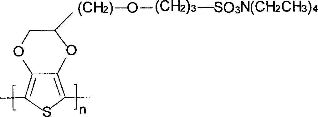
Das Polymer wurde so gebildet, wie es in Beispiel 2 beschrieben ist, außer dass als Reaktant stattdessen Tetraethylammoniumbromid eingesetzt wurde.The polymer was formed as described in Example 2, except that tetraethylammonium bromide was used instead as the reactant.
Beispiel 4Example 4
Die Fähigkeit zur Bildung von Poly[3-(2,3-dihydrothieno[3,4-b][1,4]dioxin-2-ylmethoxy)propan-1-tetrabutylammoniumsulfonat] (”PEDOTSBu4N”), das die folgende Struktur hat, wurde nachgewiesen: 
Das Polymer wurde wie folgt gebildet. Zunächst wurden 2 Gramm PEDOTSNa, 140 Milliliter Wasser, 4,5 Gramm Tetrabutylammoniumbromid und 20 Gramm Acetonitril 2 Tage lang bei Umgebungstemperatur gemischt. Dann wurde das Gemisch mit Wasser, Acetonitril oder Dimethylsulfoxid so verdünnt, dass eine Polymerkonzentration von 1 Gew.-% erreicht wurde.The polymer was formed as follows. First, 2 grams of PEDOTSNa, 140 milliliters of water, 4.5 grams of tetrabutylammonium bromide, and 20 grams of acetonitrile were mixed for 2 days at ambient temperature. Then, the mixture was diluted with water, acetonitrile or dimethylsulfoxide so as to achieve a polymer concentration of 1% by weight.
Beispiel 5Example 5
Eine Tantalanode mit einer Größe von 1,70 mm × 1,05 mm × 2,4 mm wurde bei 13,5 V in einem flüssigen Elektrolyten (wässrige Lösung von Orthophosphorsäure) bis 100 μF anodisiert. Dann wurde eine leitfähige Polymerbeschichtung gebildet, indem man die Anode 5 Minuten lang in eine Butanollösung von Eisen(III)toluolsulfonat (CLEVIOSTM C, H. C. Starck) und anschließend 1 Minute lang in 3,4-Ethylendioxythiophen (CLEVIOSTM M, H. C. Starck) eintauchte. Nach 45 Minuten Polymerisation wurde eine Schicht von Poly(3,4-ethylendioxythiophen) auf der Oberfläche des Dielektrikums gebildet. Die Teile wurden in Methanol gewaschen, um Nebenprodukte der Reaktion zu entfernen, in einem flüssigen Elektrolyten (wässrige Lösung von 4-Toluolsulfonsäure) reanodisiert und wiederum in Methanol gewaschen. Der Polymerisationszyklus wurde viermal wiederholt. Danach wurde der Teil in dispergiertes Poly[3-(2,3-dihydrothieno[3,4-b][1,4]dioxin-2-ylmethoxy)propan-1-ammoniumsulfonat] (”PEDOTSNH4” – Beispiel 1) mit einem Feststoffgehalt von 1% eingetaucht und dann 20 Minuten lang bei 125°C getrocknet. Wiederum wurde dieser Vorgang zweimal wiederholt. Dann wurden die Teile mit Graphit und Tauchsilber beschichtet und zusammengesetzt, indem man die Anoden in eine Leiterrahmentasche klebte, den Anodendraht abschnitt und mit einem Laser in den Leiterrahmentaschenüberstand schweißte und den Kondensator formte. Auf diese Weise wurden mehrere Teile (1000 Stück) zum Testen hergestellt.A tantalum anode having a size of 1.70 mm × 1.05 mm × 2.4 mm was anodized at 13.5 V in a liquid electrolyte (aqueous solution of orthophosphoric acid) to 100 μF. A conductive polymer coating was then formed by placing the anode in a butanol solution of ferric toluenesulfonate (CLEVIOS ™ C, HC Starck) for 5 minutes and then in 3,4-ethylenedioxythiophene (CLEVIOS ™ M, HC Starck) for 1 minute. dipped. After 45 minutes of polymerization, a layer of poly (3,4-ethylenedioxythiophene) was formed on the surface of the dielectric. The parts were washed in methanol to remove by-products of the reaction, re-anodized in a liquid electrolyte (aqueous solution of 4-toluenesulfonic acid) and washed again in methanol. The polymerization cycle was repeated four times. Thereafter, the part was dispersed in dispersed poly [3- (2,3-dihydro-thieno [3,4-b] [1,4] dioxin-2-ylmethoxy) propane-1-ammonium sulfonate] ("PEDOTSNH 4 " Example 1) immersed in a solids content of 1% and then dried at 125 ° C for 20 minutes. Again, this process was repeated twice. The parts were then coated with graphite and dipping silver and assembled by adhering the anodes to a ladder frame pocket, sectioning the anode wire, and laser welding into the leadframe tab protrusion and forming the capacitor. In this way, several parts (1000 pieces) were made for testing.
Beispiel 6Example 6
1000 Stück Kondensatoren wurden so hergestellt, wie es in Beispiel 5 beschrieben ist, außer dass das Poly[3-(2,3-dihydrothieno[3,4-b][1,4]dioxin-2-ylmethoxy)propan-1-ammoniumsulfonat] (”PEDOTSNH4” – Beispiel 1) als dispergiertes Polymer verwendet wurde.1000 pieces of capacitors were prepared as described in Example 5 except that the poly [3- (2,3-dihydro-thieno [3,4-b] [1,4] dioxin-2-ylmethoxy) propane-1 ammonium sulfonate] ("PEDOTSNH 4 " - Example 1) was used as the dispersed polymer.
Beispiel 7 Example 7
1000 Stück Kondensatoren wurden so hergestellt, wie es in Beispiel 5 beschrieben ist, außer dass das Poly[3-(2,3-dihydrothieno[3,4-b][1,4]dioxin-2-ylmethoxy)propan-1-tetramethylammoniumsulfonat] (”PEDOTSMe4N” – Beispiel 2) als dispergiertes Polymer verwendet wurde.1000 pieces of capacitors were prepared as described in Example 5 except that the poly [3- (2,3-dihydro-thieno [3,4-b] [1,4] dioxin-2-ylmethoxy) propane-1 tetramethylammonium sulfonate] ("PEDOTSMe 4 N" - Example 2) was used as the dispersed polymer.
Beispiel 8Example 8
1000 Stück Kondensatoren wurden so hergestellt, wie es in Beispiel 5 beschrieben ist, außer dass das Poly[3-(2,3-dihydrothieno[3,4-b][1,4]dioxin-2-ylmethoxy)propan-1-tetraethylammoniumsulfonat] (”PEDOTSEt4N” – Beispiel 3) als dispergiertes Polymer verwendet wurde.1000 pieces of capacitors were prepared as described in Example 5 except that the poly [3- (2,3-dihydro-thieno [3,4-b] [1,4] dioxin-2-ylmethoxy) propane-1 tetraethylammoniumsulfonat] ( "PEDOTSEt 4 N" - example 3) was used as the dispersed polymer.
Beispiel 9Example 9
1000 Stück Kondensatoren wurden so hergestellt, wie es in Beispiel 5 beschrieben ist, außer dass das Poly[3-(2,3-dihydrothieno[3,4-b][1,4]dioxin-2-ylmethoxy)propan-1-tetrabutylammoniumsulfonat] (”PEDOTSBu4N” – Beispiel 4) als dispergiertes Polymer verwendet wurde.1000 pieces of capacitors were prepared as described in Example 5 except that the poly [3- (2,3-dihydro-thieno [3,4-b] [1,4] dioxin-2-ylmethoxy) propane-1 tetrabutylammonium sulfonate] ("PEDOTSBu 4 N" - Example 4) was used as the dispersed polymer.
VergleichsbeispielComparative example
1000 Stück Kondensatoren wurden so hergestellt, wie es in Beispiel 5 beschrieben ist, außer dass das Poly(3,4-ethylendioxythiophen) (”CleviosTM K” – Feststoffgehalt 1%) als dispergiertes Polymer verwendet wurde.1000 pieces of capacitors were prepared as described in Example 5 except that the poly (3,4-ethylenedioxythiophene) ("Clevios ™ K" solids content 1%) was used as the dispersed polymer.
Dann wurden die fertigen Kondensatoren der Beispiele 5–9 und des Vergleichsbeispiels auf ihre elektrischen Eigenschaften getestet. Die Mittelwerte des Leckstroms, des ESR und der Kapazität sind unten in Tabelle 1 gezeigt. Tabelle 1. Elektrische Eigenschaften
Dann wurden 100 Proben der fertigen Kondensatoren der Beispiele 5–9 und des Vergleichsbeispiels nach einem ”Temperatur/Druck-Test”, wie er oben beschrieben ist, getestet. Die Ergebnisse sind unten in Tabelle 2 gezeigt. Tabelle 2: Elektrische Eigenschaften nach Temperatur/Druck-Test
Dann wurden 100 Proben der fertigen Kondensatoren der Beispiele 5–9 und des Vergleichsbeispiels nach dreimal angewendetem ”bleifreien Reflow-Löten”, wie es oben beschrieben ist, getestet. Die Ergebnisse sind unten in Tabelle 3 gezeigt. Tabelle 3: Elektrische Eigenschaften nach dreimaligem bleifreien Reflow-Löten
Diese und andere Modifikationen und Variationen der vorliegenden Erfindung können vom Fachmann praktisch umgesetzt werden, ohne vom Wesen und Umfang der vorliegenden Erfindung abzuweichen. Außerdem sollte man sich darüber im Klaren sein, dass Aspekte der verschiedenen Ausführungsformen ganz oder teilweise gegeneinander ausgetauscht werden können. Weiterhin wird der Fachmann anerkennen, dass die obige Beschreibung nur beispielhaften Charakter hat und die Erfindung, die in den beigefügten Ansprüchen näher beschrieben ist, nicht einschränken soll.These and other modifications and variations of the present invention may be practiced by those skilled in the art without departing from the spirit and scope of the present invention. In addition, it should be understood that aspects of the various embodiments may be partially or completely interchanged. Furthermore, those skilled in the art will recognize that the above description is merely exemplary in nature and is not intended to limit the invention, which is further described in the appended claims.
ZITATE ENTHALTEN IN DER BESCHREIBUNG QUOTES INCLUDE IN THE DESCRIPTION
Diese Liste der vom Anmelder aufgeführten Dokumente wurde automatisiert erzeugt und ist ausschließlich zur besseren Information des Lesers aufgenommen. Die Liste ist nicht Bestandteil der deutschen Patent- bzw. Gebrauchsmusteranmeldung. Das DPMA übernimmt keinerlei Haftung für etwaige Fehler oder Auslassungen.This list of the documents listed by the applicant has been generated automatically and is included solely for the better information of the reader. The list is not part of the German patent or utility model application. The DPMA assumes no liability for any errors or omissions.
Zitierte PatentliteraturCited patent literature
- US 5457862 [0001, 0036] US 5457862 [0001, 0036]
- US 5473503 [0001, 0036] US 5473503 [0001, 0036]
- US 5729428 [0001, 0036] US 5729428 [0001, 0036]
- US 5812367 [0001, 0036] US 5812367 [0001, 0036]
- US 6987663 [0001, 0034] US 6987663 [0001, 0034]
- US 5111327 [0013] US 5111327 [0013]
- US 6635729 [0013, 0048] US 6635729 [0013, 0048]
- US 7569158 [0017] US 7569158 [0017]
- US 6322912 [0026] US 6322912 [0026]
- US 6391275 [0026] US 6391275 [0026]
- US 6416730 [0026] US 6416730 [0026]
- US 6527937 [0026] US 6527937 [0026]
- US 6576099 [0026] US 6576099 [0026]
- US 6592740 [0026] US 6592740 [0026]
- US 6639787 [0026] US 6639787 [0026]
- US 7220397 [0026] US 7220397 [0026]
- US 6197252 [0030] US 6197252 [0030]
- US 6191936 [0031] US 6191936 [0031]
- US 5949639 [0031] US 5949639 [0031]
- US 3345545 [0031] US 3345545 [0031]
- US 4945452 [0034] US 4945452 [0034]
- US 2008/232037 [0036] US 2008/232037 [0036]
Claims (25)


Applications Claiming Priority (2)
| Application Number | Priority Date | Filing Date | Title |
|---|---|---|---|
| US12/967,157 | 2010-12-14 | ||
| US12/967,157 US8576543B2 (en) | 2010-12-14 | 2010-12-14 | Solid electrolytic capacitor containing a poly(3,4-ethylenedioxythiophene) quaternary onium salt |
Publications (1)
| Publication Number | Publication Date |
|---|---|
| DE102011088368A1 true DE102011088368A1 (en) | 2012-06-14 |
Family
ID=45475672
Family Applications (1)
| Application Number | Title | Priority Date | Filing Date |
|---|---|---|---|
| DE102011088368A Withdrawn DE102011088368A1 (en) | 2010-12-14 | 2011-12-13 | A solid electrolytic capacitor containing a poly (3,4-ethylenedioxythiophene) quaternary onium salt |
Country Status (7)
| Country | Link |
|---|---|
| US (1) | US8576543B2 (en) |
| JP (1) | JP5734833B2 (en) |
| KR (1) | KR20120089553A (en) |
| CN (1) | CN102969166B (en) |
| DE (1) | DE102011088368A1 (en) |
| GB (1) | GB2486530A (en) |
| HK (1) | HK1178313A1 (en) |
Families Citing this family (34)
| Publication number | Priority date | Publication date | Assignee | Title |
|---|---|---|---|---|
| WO2012023992A1 (en) | 2010-08-20 | 2012-02-23 | Rhodia Operations | Films containing electrically conductive polymers |
| US8971019B2 (en) | 2012-03-16 | 2015-03-03 | Avx Corporation | Wet capacitor cathode containing an alkyl-substituted poly(3,4-ethylenedioxythiophene) |
| JP6040615B2 (en) * | 2012-07-03 | 2016-12-07 | 東ソー株式会社 | Thiophene compound, water-soluble conductive polymer and aqueous solution thereof, and production method thereof |
| WO2014007299A1 (en) * | 2012-07-03 | 2014-01-09 | 東ソー株式会社 | Polythiophenes, water-soluble conductive polymer using same, and method for producing same |
| US9718905B2 (en) | 2012-07-03 | 2017-08-01 | Tosoh Corporation | Polythiophene, water-soluble electrically conductive polymer using it, and method for producing it |
| GB201212051D0 (en) | 2012-07-06 | 2012-08-22 | Zyk S A | Energy storage apparatus |
| US9236192B2 (en) * | 2013-08-15 | 2016-01-12 | Avx Corporation | Moisture resistant solid electrolytic capacitor assembly |
| KR102078008B1 (en) * | 2014-02-13 | 2020-02-17 | 삼성전기주식회사 | Solid electrolytic capacitor, manufacturing of the same and chip-type electronic part |
| JP2016188348A (en) * | 2015-03-30 | 2016-11-04 | 東ソー株式会社 | Thiophene polymer, composition thereof, and use therefor |
| US9972444B2 (en) | 2015-05-29 | 2018-05-15 | Avx Corporation | Solid electrolytic capacitor element for use in dry conditions |
| US9672989B2 (en) * | 2015-05-29 | 2017-06-06 | Avx Corporation | Solid electrolytic capacitor assembly for use in a humid atmosphere |
| US9767963B2 (en) * | 2015-05-29 | 2017-09-19 | Avx Corporation | Solid electrolytic capacitor with an ultrahigh capacitance |
| US9991055B2 (en) | 2015-05-29 | 2018-06-05 | Avx Corporation | Solid electrolytic capacitor assembly for use at high temperatures |
| US10186382B2 (en) * | 2016-01-18 | 2019-01-22 | Avx Corporation | Solid electrolytic capacitor with improved leakage current |
| TWI618103B (en) * | 2016-08-08 | 2018-03-11 | 鈺冠科技股份有限公司 | Solid electrolytic capacitor package structure using nanomaterials and capacitor unit thereof, and method of manufacturing a capacitor unit |
| US10763046B2 (en) * | 2016-09-15 | 2020-09-01 | Avx Corporation | Solid electrolytic capacitor with improved leakage current |
| JP7055140B2 (en) * | 2016-10-18 | 2022-04-15 | キョーセラ・エイブイエックス・コンポーネンツ・コーポレーション | Solid electrolytic capacitors with improved performance at high temperatures and voltages |
| WO2018075330A2 (en) | 2016-10-18 | 2018-04-26 | Avx Corporation | Solid electrolytic capacitor with improved leakage current |
| WO2018075327A1 (en) * | 2016-10-18 | 2018-04-26 | Avx Corporation | Solid electrolytic capacitor assembly |
| US10475591B2 (en) * | 2016-11-15 | 2019-11-12 | Avx Corporation | Solid electrolytic capacitor for use in a humid atmosphere |
| CN115881437A (en) | 2017-03-06 | 2023-03-31 | 京瓷Avx元器件公司 | Solid electrolytic capacitor assembly |
| CN110720131B (en) | 2017-07-03 | 2022-05-31 | 京瓷Avx元器件公司 | Solid electrolytic capacitor assembly |
| US11257628B2 (en) | 2017-07-03 | 2022-02-22 | KYOCERA AVX Components Corporation | Solid electrolytic capacitor containing a nanocoating |
| EP3834217A4 (en) * | 2018-08-10 | 2022-05-11 | KYOCERA AVX Components Corporation | Solid electrolytic capacitor containing an intrinsically conductive polymer |
| WO2020033820A1 (en) | 2018-08-10 | 2020-02-13 | Avx Corporation | Solid electrolytic capacitor formed from conductive polymer particles |
| US11183342B2 (en) | 2018-08-10 | 2021-11-23 | Avx Corporation | Solid electrolytic capacitor containing polyaniline |
| US11289276B2 (en) * | 2018-10-30 | 2022-03-29 | Global Advanced Metals Japan K.K. | Porous metal foil and capacitor anodes made therefrom and methods of making same |
| WO2020123577A1 (en) | 2018-12-11 | 2020-06-18 | Avx Corporation | Solid electrolytic capacitor containing an intrinsically conductive polymer |
| WO2021055707A1 (en) * | 2019-09-18 | 2021-03-25 | Avx Corporation | Solid electroltyic capacitor for use at high voltages |
| CN111048319A (en) * | 2019-11-13 | 2020-04-21 | 株洲宏达电子股份有限公司 | Sheet-type tantalum capacitor manufactured by aqueous-phase electrochemical polymerization of thiophene and manufacturing method thereof |
| JP2023506714A (en) | 2019-12-10 | 2023-02-20 | キョーセラ・エイブイエックス・コンポーネンツ・コーポレーション | Solid electrolytic capacitor containing precoat and intrinsically conductive polymer |
| DE112020006024T5 (en) | 2019-12-10 | 2022-10-06 | KYOCERA AVX Components Corporation | Tantalum capacitor with increased stability |
| US11631548B2 (en) | 2020-06-08 | 2023-04-18 | KYOCERA AVX Components Corporation | Solid electrolytic capacitor containing a moisture barrier |
| US11837415B2 (en) | 2021-01-15 | 2023-12-05 | KYOCERA AVX Components Corpration | Solid electrolytic capacitor |
Citations (19)
| Publication number | Priority date | Publication date | Assignee | Title |
|---|---|---|---|---|
| US3345545A (en) | 1964-11-27 | 1967-10-03 | Johnson Matthey & Mallory Ltd | Solid electrolytic capacitor having minimum anode impedance |
| US4945452A (en) | 1989-11-30 | 1990-07-31 | Avx Corporation | Tantalum capacitor and method of making same |
| US5111327A (en) | 1991-03-04 | 1992-05-05 | General Electric Company | Substituted 3,4-polymethylenedioxythiophenes, and polymers and electro responsive devices made therefrom |
| US5457862A (en) | 1993-11-10 | 1995-10-17 | Nec Corporation | Method of manufacturing solid electrolytic capacitor |
| US5473503A (en) | 1993-07-27 | 1995-12-05 | Nec Corporation | Solid electrolytic capacitor and method for manufacturing the same |
| US5729428A (en) | 1995-04-25 | 1998-03-17 | Nec Corporation | Solid electrolytic capacitor with conductive polymer as solid electrolyte and method for fabricating the same |
| US5812367A (en) | 1996-04-04 | 1998-09-22 | Matsushita Electric Industrial Co., Ltd. | Solid electrolytic capacitors comprising a conductive layer made of a polymer of pyrrole or its derivative |
| US5949639A (en) | 1996-09-27 | 1999-09-07 | Rohm Co., Ltd. | Capacitor element for solid electrolytic capacitor, device and process for making the same |
| US6191936B1 (en) | 1999-04-12 | 2001-02-20 | Vishay Sprague, Inc. | Capacitor having textured pellet and method for making same |
| US6197252B1 (en) | 1997-01-13 | 2001-03-06 | Avx Limited | Binder removal |
| US6322912B1 (en) | 1998-09-16 | 2001-11-27 | Cabot Corporation | Electrolytic capacitor anode of valve metal oxide |
| US6391275B1 (en) | 1998-09-16 | 2002-05-21 | Cabot Corporation | Methods to partially reduce a niobium metal oxide and oxygen reduced niobium oxides |
| US6416730B1 (en) | 1998-09-16 | 2002-07-09 | Cabot Corporation | Methods to partially reduce a niobium metal oxide oxygen reduced niobium oxides |
| US6576099B2 (en) | 2000-03-23 | 2003-06-10 | Cabot Corporation | Oxygen reduced niobium oxides |
| US6635729B1 (en) | 2000-02-03 | 2003-10-21 | Bayer Aktinegesellschaft | Process for the preparation of water-soluble π-conjugated polymers |
| US6639787B2 (en) | 2000-11-06 | 2003-10-28 | Cabot Corporation | Modified oxygen reduced valve metal oxides |
| US6987663B2 (en) | 2003-10-17 | 2006-01-17 | H.C. Starck Gmbh | Electrolytic capacitors with a polymeric outer layer |
| US20080232037A1 (en) | 2007-03-21 | 2008-09-25 | Avx Corporation | Solid electrolytic capacitor containing a conductive polymer |
| US7569158B2 (en) | 2004-10-13 | 2009-08-04 | Air Products And Chemicals, Inc. | Aqueous dispersions of polythienothiophenes with fluorinated ion exchange polymers as dopants |
Family Cites Families (71)
| Publication number | Priority date | Publication date | Assignee | Title |
|---|---|---|---|---|
| US2453103A (en) | 1944-02-25 | 1948-11-02 | Du Pont | Decarboxylation of 3,4-dihydroxy-2,5-dicarboxythiophene |
| JPH03229075A (en) | 1990-01-31 | 1991-10-11 | Teijin Seiki Co Ltd | Counter balance valve with relief function |
| EP0440957B1 (en) | 1990-02-08 | 1996-03-27 | Bayer Ag | New polythiophene dispersions, their preparation and their use |
| US5344902A (en) | 1991-06-18 | 1994-09-06 | Occidental Research Corporation | Polymerization with initiator and quaternary ammonium salt |
| DE4211461A1 (en) | 1992-04-06 | 1993-10-07 | Agfa Gevaert Ag | Antistatic plastic parts |
| DE4319042A1 (en) | 1993-06-08 | 1994-12-15 | Agfa Gevaert Ag | New thiophene derivatives |
| WO1995016681A1 (en) | 1993-12-14 | 1995-06-22 | The Trustees Of The University Of Pennsylvania | Derivatized polythiophenes and devices comprising same |
| US6517892B1 (en) * | 1999-05-24 | 2003-02-11 | Showa Denko K.K. | Solid electrolytic capacitor and method for producing the same |
| DE10016723A1 (en) | 2000-04-04 | 2001-10-11 | Bayer Ag | Process for the preparation of dialkoxythiophenes and alkylenedioxythiophenes |
| DE10029075A1 (en) | 2000-06-13 | 2001-12-20 | Bayer Ag | Two- or three-stage preparation of high-purity 3,4-alkylenedioxythiophene-2,5-dicarboxylic derivatives or acids is effected without isolation of the intermediates |
| AU2002221869A1 (en) | 2000-11-22 | 2002-06-03 | Bayer Aktiengesellschaft | Dispersible polymer powders |
| DE10058116A1 (en) * | 2000-11-22 | 2002-05-23 | Bayer Ag | Production of polythiophene for use in conductive and antistatic coatings involves reacting 3,4-alkylenedioxythiophene with organic sulfonic acid, oxidising agent and phase transfer catalyst in anhydrous solvent |
| US7094865B2 (en) | 2001-03-29 | 2006-08-22 | Agfa Gevaert | Thiophenes and polymers derived therefrom |
| AU2002349041A1 (en) | 2001-12-04 | 2003-06-17 | Agfa-Gevaert | Process for preparing an aqueous or non-aqueous solution or dispersion of a polythiophene or thiophene copolymer |
| EP1321483A1 (en) | 2001-12-20 | 2003-06-25 | Agfa-Gevaert | 3,4-alkylenedioxythiophene compounds and polymers thereof |
| DE10164260A1 (en) | 2001-12-27 | 2003-07-17 | Bayer Ag | Process for the production of undoped, neutral polyethylene dioxythiophene, and corresponding polyethylene dioxythiophenes |
| DE10229218A1 (en) | 2002-06-28 | 2004-01-22 | H.C. Starck Gmbh | Alkylenedioxythiophene dimers and trimers |
| DE10237577A1 (en) | 2002-08-16 | 2004-02-26 | H.C. Starck Gmbh | Substituted poly (alkylenedioxythiophenes) as solid electrolytes in electrolytic capacitors |
| AU2002337064A1 (en) | 2002-09-02 | 2004-03-19 | Agfa-Gevaert | New 3,4-alkylenedioxythiophenedioxide compounds and polymers comprising monomeric units thereof |
| DE10250808B3 (en) | 2002-10-31 | 2004-04-08 | Honeywell Specialty Chemicals Seelze Gmbh | Preparation of electrolyte containing tetraalkylammonium tetrafluoroborate, used in electrochemical cell or capacitor, involves mixing tetraalkylammonium halide and metal tetrafluoroborate in (partly) water-miscible organic solvent |
| US7578859B2 (en) | 2002-12-02 | 2009-08-25 | The United States Of America As Represented By The Secretary Of The Navy | Poly (3,4-alkylenedioxythiophene)-based capacitors using ionic liquids as supporting electrolytes |
| DE10257539A1 (en) | 2002-12-10 | 2004-07-01 | H.C. Starck Gmbh | Process for the preparation of 2,2'-di (3,4-ethylenedioxythiophene) s |
| DE10302086A1 (en) | 2003-01-21 | 2004-07-29 | Bayer Ag | Alkylenedioxythiophenes and poly (alkylenedioxythiophenes) with mesogenic groups |
| MXPA05010361A (en) | 2003-04-02 | 2005-11-17 | Starck H C Gmbh | Specific oxidation agents for producing conductive polymers. |
| DE10331673A1 (en) | 2003-07-14 | 2005-02-10 | H.C. Starck Gmbh | Polythiophene with alkyleneoxythiathiophene units in electrolytic capacitors |
| DE502004011120D1 (en) | 2003-07-15 | 2010-06-17 | Starck H C Gmbh | niobium suboxide powder |
| DE10333156A1 (en) | 2003-07-22 | 2005-02-24 | H.C. Starck Gmbh | Process for the preparation of niobium suboxide |
| DE10343873A1 (en) | 2003-09-23 | 2005-04-21 | Starck H C Gmbh | Process for the purification of thiophenes |
| US7105237B2 (en) | 2003-10-01 | 2006-09-12 | The University Of Connecticut | Substituted thieno[3,4-B]thiophene polymers, method of making, and use thereof |
| US20070139862A1 (en) | 2003-10-09 | 2007-06-21 | Kaneka Corporation | Electrode composite body, electrolyte, and redox capacitor |
| DE10347702B4 (en) | 2003-10-14 | 2007-03-29 | H.C. Starck Gmbh | Sintered body based on niobium suboxide |
| DE10357571A1 (en) | 2003-12-10 | 2005-07-28 | H.C. Starck Gmbh | Multifunctional 3,4-alkylenedioxythiophene derivatives and electrically conductive polymers containing them |
| DE102004002420A1 (en) | 2004-01-16 | 2005-08-11 | Basf Ag | Distillation of ionic liquids |
| US7116548B2 (en) | 2004-04-23 | 2006-10-03 | Kemet Electronics Corporation | Fluted anode with minimal density gradients and capacitor comprising same |
| DE102004022110A1 (en) | 2004-05-05 | 2005-12-01 | H.C. Starck Gmbh | Process for the preparation of electrolytic capacitors |
| JP2006028214A (en) | 2004-07-12 | 2006-02-02 | Nagase Chemtex Corp | Method for producing aqueous dispersion of complex of poly(3,4-dialkoxythiophene) with polyanion |
| CN1737072B (en) | 2004-08-18 | 2011-06-08 | 播磨化成株式会社 | Conductive adhesive agent and process for manufacturing article using the conductive adhesive agent |
| JP5106127B2 (en) | 2005-03-04 | 2012-12-26 | ハネウェル・インターナショナル・インコーポレーテッド | Method for purifying quaternary onium salts |
| US7438832B2 (en) | 2005-03-29 | 2008-10-21 | Eastman Kodak Company | Ionic liquid and electronically conductive polymer mixtures |
| DE102005016727A1 (en) | 2005-04-11 | 2006-10-26 | H.C. Starck Gmbh | Electrolytic capacitors with polymeric outer layer and process for their preparation |
| WO2006132141A1 (en) | 2005-06-09 | 2006-12-14 | National University Corporation, Tokyo University Of Agriculture And Technology | Electrolytic capacitor element and process for producing the same |
| US20100103590A1 (en) * | 2005-06-27 | 2010-04-29 | Showa Denko K.K. | Solid electrolytic capacitor and production method thereof |
| JP4978827B2 (en) * | 2005-06-27 | 2012-07-18 | 株式会社村田製作所 | Solid electrolytic capacitor and manufacturing method thereof |
| DE102005033839A1 (en) | 2005-07-20 | 2007-01-25 | H.C. Starck Gmbh | Electrolytic capacitors with a polymeric outer layer and process for their preparation |
| DE102005043829A1 (en) | 2005-09-13 | 2007-04-05 | H.C. Starck Gmbh | Process for the production of electrolytic capacitors with high nominal voltage |
| DE102005043828A1 (en) * | 2005-09-13 | 2007-03-22 | H.C. Starck Gmbh | Process for the preparation of electrolytic capacitors |
| DE102005053646A1 (en) | 2005-11-10 | 2007-05-16 | Starck H C Gmbh Co Kg | Polymer coatings with improved solvent resistance |
| US7973180B2 (en) | 2005-11-17 | 2011-07-05 | H.C. Starck Gmbh | Process for producing aqueous dispersion of composite of poly(3,4-dialkoxythiophene) with polyanion |
| DE102006002797A1 (en) | 2006-01-20 | 2007-08-02 | H. C. Starck Gmbh & Co. Kg | Preparation of polythiophene, useful e.g. in telecommunication technology, for the preparation of solid electrolytes and electrodes, comprises oxidative polymerization of thiophene using hypervalent iodine compound as oxidizing agent |
| US7714124B2 (en) | 2006-03-27 | 2010-05-11 | The Procter & Gamble Company | Methods for modifying cellulosic polymers in ionic liquids |
| DE102006020744A1 (en) | 2006-05-04 | 2007-11-08 | H. C. Starck Gmbh & Co. Kg | Process for the stabilization of thiophene derivatives |
| DE102006044067A1 (en) | 2006-09-20 | 2008-03-27 | H.C. Starck Gmbh | Process for the preparation of polythiophenes |
| US7745520B2 (en) | 2006-10-05 | 2010-06-29 | The Regents Of The University Of California | Hybrid polymer light-emitting devices |
| WO2008095069A2 (en) | 2007-01-31 | 2008-08-07 | Sigma-Aldrich Co. | High stability polyionic liquid salts |
| US8027150B2 (en) | 2007-02-09 | 2011-09-27 | Kaneka Corporation | Conductive polymer solid electrolytic capacitor |
| US7736398B2 (en) | 2007-02-26 | 2010-06-15 | Kaneka Corporation | Method of manufacturing conductive polymer electrolytic capacitor |
| CZ301500B6 (en) | 2007-04-27 | 2010-03-24 | Výzkumný ústav organických syntéz a.s. | Process for preparing 3,4-alkylenedioxothiophenes |
| WO2008143234A1 (en) * | 2007-05-21 | 2008-11-27 | Showa Denko K. K. | Method and apparatus for manufacturing solid electrolytic capacitor |
| DE102007041722A1 (en) | 2007-09-04 | 2009-03-05 | H.C. Starck Gmbh | Process for the preparation of conductive polymers |
| DE102007046904A1 (en) | 2007-09-28 | 2009-04-09 | H.C. Starck Gmbh | Particles with core-shell structure for conductive layers |
| DE102007048212A1 (en) | 2007-10-08 | 2009-04-09 | H.C. Starck Gmbh | Process for the preparation of electrolytic capacitors with polymeric interlayer |
| US8094434B2 (en) * | 2008-04-01 | 2012-01-10 | Avx Corporation | Hermetically sealed capacitor assembly |
| JP4256470B1 (en) | 2008-04-04 | 2009-04-22 | パナソニック株式会社 | Conductive polymer actuator, manufacturing method thereof, and driving method thereof |
| DE102008023008A1 (en) | 2008-05-09 | 2009-11-12 | H.C. Starck Gmbh | Novel polythiophene-polyanion complexes in non-polar organic solvents |
| DE102008024805A1 (en) | 2008-05-23 | 2009-12-03 | H.C. Starck Gmbh | Process for the preparation of electrolytic capacitors |
| US8790537B2 (en) | 2008-06-09 | 2014-07-29 | Council Of Scientific & Industrial Research | Process for the preparation of solid polymer electrolytes using ionic liquids |
| US20090320771A1 (en) | 2008-06-10 | 2009-12-31 | Matheson Tri-Gas | Ionic liquid mediums for holding solid phase process gas precursors |
| DE102008032578A1 (en) | 2008-07-11 | 2010-01-14 | H.C. Starck Gmbh | Process for the preparation of electrolytic capacitors |
| DE102008036525A1 (en) | 2008-08-06 | 2010-02-11 | H.C. Starck Gmbh | Process for the preparation of polythiophenes |
| DE102009007594A1 (en) | 2009-02-05 | 2010-08-12 | H.C. Starck Clevios Gmbh | Process for the preparation of electrolytic capacitors with a polymeric outer layer. |
| DE102009012660A1 (en) | 2009-03-13 | 2010-09-16 | H.C. Starck Clevios Gmbh | Polymer coatings with improved temperature stability |
-
2010
- 2010-12-14 US US12/967,157 patent/US8576543B2/en active Active
-
2011
- 2011-11-24 GB GB1120300.7A patent/GB2486530A/en not_active Withdrawn
- 2011-12-13 DE DE102011088368A patent/DE102011088368A1/en not_active Withdrawn
- 2011-12-13 KR KR1020110133657A patent/KR20120089553A/en not_active Application Discontinuation
- 2011-12-14 CN CN201110462214.7A patent/CN102969166B/en active Active
- 2011-12-14 JP JP2011290562A patent/JP5734833B2/en active Active
-
2013
- 2013-04-29 HK HK13105149.4A patent/HK1178313A1/en unknown
Patent Citations (22)
| Publication number | Priority date | Publication date | Assignee | Title |
|---|---|---|---|---|
| US3345545A (en) | 1964-11-27 | 1967-10-03 | Johnson Matthey & Mallory Ltd | Solid electrolytic capacitor having minimum anode impedance |
| US4945452A (en) | 1989-11-30 | 1990-07-31 | Avx Corporation | Tantalum capacitor and method of making same |
| US5111327A (en) | 1991-03-04 | 1992-05-05 | General Electric Company | Substituted 3,4-polymethylenedioxythiophenes, and polymers and electro responsive devices made therefrom |
| US5473503A (en) | 1993-07-27 | 1995-12-05 | Nec Corporation | Solid electrolytic capacitor and method for manufacturing the same |
| US5457862A (en) | 1993-11-10 | 1995-10-17 | Nec Corporation | Method of manufacturing solid electrolytic capacitor |
| US5729428A (en) | 1995-04-25 | 1998-03-17 | Nec Corporation | Solid electrolytic capacitor with conductive polymer as solid electrolyte and method for fabricating the same |
| US5812367A (en) | 1996-04-04 | 1998-09-22 | Matsushita Electric Industrial Co., Ltd. | Solid electrolytic capacitors comprising a conductive layer made of a polymer of pyrrole or its derivative |
| US5949639A (en) | 1996-09-27 | 1999-09-07 | Rohm Co., Ltd. | Capacitor element for solid electrolytic capacitor, device and process for making the same |
| US6197252B1 (en) | 1997-01-13 | 2001-03-06 | Avx Limited | Binder removal |
| US6322912B1 (en) | 1998-09-16 | 2001-11-27 | Cabot Corporation | Electrolytic capacitor anode of valve metal oxide |
| US6391275B1 (en) | 1998-09-16 | 2002-05-21 | Cabot Corporation | Methods to partially reduce a niobium metal oxide and oxygen reduced niobium oxides |
| US6416730B1 (en) | 1998-09-16 | 2002-07-09 | Cabot Corporation | Methods to partially reduce a niobium metal oxide oxygen reduced niobium oxides |
| US6527937B2 (en) | 1998-09-16 | 2003-03-04 | Cabot Corporation | Method of making a capacitor anode of a pellet of niobium oxide |
| US6592740B2 (en) | 1998-09-16 | 2003-07-15 | Cabot Corporation | Methods to make capacitors containing a partially reduced niobium metal oxide |
| US6191936B1 (en) | 1999-04-12 | 2001-02-20 | Vishay Sprague, Inc. | Capacitor having textured pellet and method for making same |
| US6635729B1 (en) | 2000-02-03 | 2003-10-21 | Bayer Aktinegesellschaft | Process for the preparation of water-soluble π-conjugated polymers |
| US6576099B2 (en) | 2000-03-23 | 2003-06-10 | Cabot Corporation | Oxygen reduced niobium oxides |
| US6639787B2 (en) | 2000-11-06 | 2003-10-28 | Cabot Corporation | Modified oxygen reduced valve metal oxides |
| US7220397B2 (en) | 2000-11-06 | 2007-05-22 | Cabot Corporation | Modified oxygen reduced valve metal oxides |
| US6987663B2 (en) | 2003-10-17 | 2006-01-17 | H.C. Starck Gmbh | Electrolytic capacitors with a polymeric outer layer |
| US7569158B2 (en) | 2004-10-13 | 2009-08-04 | Air Products And Chemicals, Inc. | Aqueous dispersions of polythienothiophenes with fluorinated ion exchange polymers as dopants |
| US20080232037A1 (en) | 2007-03-21 | 2008-09-25 | Avx Corporation | Solid electrolytic capacitor containing a conductive polymer |
Also Published As
| Publication number | Publication date |
|---|---|
| KR20120089553A (en) | 2012-08-13 |
| GB201120300D0 (en) | 2012-01-04 |
| JP2012129531A (en) | 2012-07-05 |
| CN102969166A (en) | 2013-03-13 |
| US8576543B2 (en) | 2013-11-05 |
| CN102969166B (en) | 2016-03-16 |
| GB2486530A (en) | 2012-06-20 |
| US20120147529A1 (en) | 2012-06-14 |
| JP5734833B2 (en) | 2015-06-17 |
| HK1178313A1 (en) | 2013-09-06 |
Similar Documents
| Publication | Publication Date | Title |
|---|---|---|
| DE102011088368A1 (en) | A solid electrolytic capacitor containing a poly (3,4-ethylenedioxythiophene) quaternary onium salt | |
| DE102011088366A1 (en) | Conductive coating for use in electrolytic capacitors | |
| EP1927120B1 (en) | Method for producing electrolytic capacitors | |
| EP2283497B1 (en) | Method for producing solid electrolyte capacitors | |
| DE102012018976A1 (en) | Use of mixtures of self-doped and externally doped conductive polymers in a capacitor | |
| DE102014225816A1 (en) | Stable solid electrolytic capacitor containing a nanocomposite | |
| DE102010048177A1 (en) | External coating for a solid electrolytic capacitor | |
| DE102011117192A1 (en) | Solid electrolytic capacitor for use in high voltage and high temperature applications | |
| DE102014208944A1 (en) | A solid electrolytic capacitor containing conductive polymer particles | |
| DE102013214126A1 (en) | Solid electrolytic capacitor with improved properties at high voltages | |
| DE102011109752A1 (en) | A solid electrolytic capacitor assembly | |
| DE202006021121U1 (en) | Electrolytic capacitors with high nominal voltage | |
| DE102014204323A1 (en) | Solid electrolytic capacitor for use in extreme conditions | |
| DE102010047087A1 (en) | Process for improving the electrical characteristics in capacitors containing PEDOT / PSS as a solid electrolyte by a polyalkylene glycol | |
| DE102013213723A1 (en) | Solid electrolytic capacitor with increased wet-to-dry capacity | |
| DE102013213720A1 (en) | Temperature stable solid electrolytic capacitor | |
| DE102014207581A1 (en) | Multiple notched anode for electrolytic capacitor | |
| DE102011108509A1 (en) | Mechanically robust solid electrolytic capacitor assembly | |
| DE102016208802A1 (en) | Solid electrolytic capacitor assembly for use in a humid atmosphere | |
| DE102014214966A1 (en) | Thin wire / thick wire connection assembly for electrolytic capacitor | |
| DE102011087197A1 (en) | Multilayer conductive polymer coatings for use in high voltage solid electrolytic capacitors | |
| DE102013213728A1 (en) | Solid electrolytic capacitor used in space and military fields, comprises sintered porous anode, dielectric layer covering anode, and solid electrolyte comprising conductive polymer, and nonionic surfactant covering dielectric layer | |
| DE102012223637A1 (en) | Liquid condenser containing an improved anode | |
| DE102016208807A1 (en) | Solid electrolytic capacitor element for use in dry conditions | |
| DE102016214217A1 (en) | Multiple connection wires using a carrier wire for low ESR electrolytic capacitors |
Legal Events
| Date | Code | Title | Description |
|---|---|---|---|
| R120 | Application withdrawn or ip right abandoned | ||
| R120 | Application withdrawn or ip right abandoned |
Effective date: 20141206 |