DE19983379B4 - Temperature control of electronic devices using power train feedback - Google Patents
Temperature control of electronic devices using power train feedback Download PDFInfo
- Publication number
- DE19983379B4 DE19983379B4 DE19983379T DE19983379T DE19983379B4 DE 19983379 B4 DE19983379 B4 DE 19983379B4 DE 19983379 T DE19983379 T DE 19983379T DE 19983379 T DE19983379 T DE 19983379T DE 19983379 B4 DE19983379 B4 DE 19983379B4
- Authority
- DE
- Germany
- Prior art keywords
- temperature
- power
- signal
- heat exchanger
- power consumption
- Prior art date
- Legal status (The legal status is an assumption and is not a legal conclusion. Google has not performed a legal analysis and makes no representation as to the accuracy of the status listed.)
- Expired - Lifetime
Links
Images


Classifications
-
- G—PHYSICS
- G05—CONTROLLING; REGULATING
- G05D—SYSTEMS FOR CONTROLLING OR REGULATING NON-ELECTRIC VARIABLES
- G05D23/00—Control of temperature
- G05D23/19—Control of temperature characterised by the use of electric means
- G05D23/20—Control of temperature characterised by the use of electric means with sensing elements having variation of electric or magnetic properties with change of temperature
- G05D23/24—Control of temperature characterised by the use of electric means with sensing elements having variation of electric or magnetic properties with change of temperature the sensing element having a resistance varying with temperature, e.g. a thermistor
-
- H—ELECTRICITY
- H01—ELECTRIC ELEMENTS
- H01L—SEMICONDUCTOR DEVICES NOT COVERED BY CLASS H10
- H01L23/00—Details of semiconductor or other solid state devices
- H01L23/34—Arrangements for cooling, heating, ventilating or temperature compensation ; Temperature sensing arrangements
-
- G—PHYSICS
- G05—CONTROLLING; REGULATING
- G05D—SYSTEMS FOR CONTROLLING OR REGULATING NON-ELECTRIC VARIABLES
- G05D23/00—Control of temperature
- G05D23/19—Control of temperature characterised by the use of electric means
- G05D23/20—Control of temperature characterised by the use of electric means with sensing elements having variation of electric or magnetic properties with change of temperature
-
- H—ELECTRICITY
- H01—ELECTRIC ELEMENTS
- H01L—SEMICONDUCTOR DEVICES NOT COVERED BY CLASS H10
- H01L2924/00—Indexing scheme for arrangements or methods for connecting or disconnecting semiconductor or solid-state bodies as covered by H01L24/00
- H01L2924/0001—Technical content checked by a classifier
- H01L2924/0002—Not covered by any one of groups H01L24/00, H01L24/00 and H01L2224/00
Abstract
Verfahren zum Regeln einer Temperatur eines Bauelements mit einem Wärme-Kontroller und einem mit dem Bauelement in leitendem Kontakt stehenden Wärmetauscher als Temperaturerzwingungssystem, wobei das Verfahren umfasst: dass ein Parameter gemessen wird, der mit dem Energieverbrauch durch das Bauelement in Beziehung steht, und dass der Wärmetauscher mit dem Wärme-Kontroller geregelt wird, indem der gemessene Parameter, der mit dem Energieverbrauch durch das Bauelement in Beziehung steht, verwendet wird, um die Temperatur des Bauelements zu regeln, dadurch gekennzeichnet, dass das Regeln der Einstellung der Temperatur des Wärmetauschers umfasst, dass eine erste Gleichung dazu verwendet wird, die Temperatur des Bauelements zu bestimmen, und wobei die erste Gleichung ist: die Temperatur des Bauelements = Ktheta·Ped + Tfs,wobei Ktheta eine Konstante ist, die aus einem Wärmewiderstand zwischen dem Bauelement und dem Wärmetauscher abgeleitet wird, Ped der Leistungsgebrauch des Bauelements ist, Tfs eine Temperatur an der Oberfläche zwischen dem Bauelement und dem...A method of controlling a temperature of a device having a thermal controller and a device in conductive contact with the heat exchanger as a temperature forcing system, the method comprising: measuring a parameter related to the energy consumption by the device, and that Heat exchanger is controlled with the heat controller by the measured parameter, which is related to the energy consumption through the device, is used to regulate the temperature of the device, characterized in that the regulating comprises the adjustment of the temperature of the heat exchanger, that a first equation is used to determine the temperature of the device, and wherein the first equation is: the temperature of the device = Ktheta * Ped + Tfs, where Ktheta is a constant derived from a thermal resistance between the device and the heat exchanger becomes, Ped the performance use of the Baueleme nts, Tfs is a temperature at the surface between the device and the ...
Description
HINTERGRUND DER ERFINDUNGBACKGROUND OF THE INVENTION
1. Gebiet der Erfindung1. Field of the invention
Diese Erfindung betrifft ein Verfahren zum Regeln einer Temperatur eines elektronischen Bauelements gemäß dem Oberbegriff des Anspruchs 1 sowie ein zur Ausführung des Verfahrens eingerichtetes System gemäß dem Oberbegriff des Anspruchs 16. Solch ein Verfahren sowie solch ein System sind beispielsweise aus der
2. Beschreibung des Standes der Technik2. Description of the Related Art
Die vorliegende Erfindung betrifft Temperaturregelungssysteme, die die Temperatur eines elektronischen Bauelements bei oder nahe einer konstanten Solltemperatur halten, während das Bauelement betrieben oder geprüft wird. Zwei Beispiele elektronischer Bauelemente, die am besten bei einer konstanten oder nahe einer konstanten Temperatur betrieben werden, sind verpackte integrierte Chips und bloße Chips, die unverpackt sind. Das Halten der Chip-Temperatur nahe eines konstanten Sollwertes ist nicht schwierig, wenn die Energiedissipation des Chips während des Betriebs oder Prüfens konstant ist oder in einem kleinen Bereich schwankt. Eine Möglichkeit einer Handhabung einer derartigen Situation ist es, den Chip über einen festen Wärmewiderstand mit einer Wärmemasse zu koppeln, die auf einer festen Temperatur liegt. Aber wenn die momentane Energiedissipation des Chips während des Betreibens oder Prüfens in einem weiten Bereich nach oben und nach unten variiert, ist dann das Halten der Chip-Temperatur nahe eines konstanten Sollwertes sehr schwierig.The present invention relates to temperature control systems that maintain the temperature of an electronic device at or near a constant desired temperature while the device is being operated or tested. Two examples of electronic devices that are best operated at a constant or near constant temperature are packaged integrated chips and bare chips that are unpackaged. Keeping the chip temperature near a constant set point is not difficult if the energy dissipation of the chip during operation or testing is constant or fluctuates within a small range. One way of handling such a situation is to couple the chip via a fixed thermal resistor to a thermal mass that is at a fixed temperature. But if the current energy dissipation of the chip varies up and down in a wide range during operation or testing, then keeping the chip temperature close to a constant setpoint is very difficult.
Es werden verschiedene Temperaturerzwingungssysteme dazu verwendet, auf die Temperaturschwankung des Chips anzusprechen, die durch eine weit variierende Energiedissipation des Chips hervorgerufen wird. Gewöhnlich werden Rückkopplungsverfahren dazu verwendet, die variierende Temperatur zu erfassen. Typische Ansätze umfassen die Verwendung einer Temperaturerfassungseinrichtung, wie beispielsweise eines Thermoelementes, die auf der Chip-Verpackung oder dem Chip selbst montiert ist. Ein weiterer Ansatz ist es, eine Temperaturerfassungseinrichtung, wie beispielsweise eine Wärme-Diode in die Chip-Schaltung zu integrieren. Eine derartige Temperaturerfassungseinrichtung würde dazu verwendet werden, Änderungen der Temperatur des Chips zu erfassen und dann das Temperaturerzwingungssystem geeignet einzustellen.Various temperature enforcement systems are used to respond to the temperature variation of the chip, which is caused by widely varying energy dissipation of the chip. Usually, feedback methods are used to detect the varying temperature. Typical approaches include the use of a temperature sensing device, such as a thermocouple, mounted on the chip package or the chip itself. Another approach is to integrate a temperature detector, such as a heat diode, into the chip circuit. Such a temperature detector would be used to detect changes in the temperature of the chip and then adjust the temperature forcing system appropriately.
Es gibt einige Probleme mit der Verwendung von Temperaturerfassungseinrichtungen. Im Fall von verpackten Chips wird ein außen angebrachtes Thermoelement die Temperatur der Verpackungsoberfläche angeben und nicht die Temperatur des Chips innerhalb der Verpackung. Bei manchem Energiedissipationsniveau wird diese Temperaturdifferenz für das Prüfungsergebnis signifikant sein. Die Verwendung von Temperatursensoren, die in den Chip selbst integriert sind, spricht dieses Problem an, wirft aber andere Probleme auf. Es ist keine typische Praxis für die Chip-Hersteller, Temperatursensoren auf dem Chip zu integrieren. Selbst wenn dies der Fall wäre, hätte jeder Temperatursensor des Chips einzigartige Kalibrierungserfordernisse. All das Obige stellt für die Chip-Herstellung mit hohem Volumen Probleme dar.There are some problems with the use of temperature sensing devices. In the case of packaged chips, an externally mounted thermocouple will indicate the temperature of the packaging surface and not the temperature of the chip within the package. For some energy dissipation levels, this temperature difference will be significant to the test result. The use of temperature sensors integrated into the chip itself addresses this problem but poses other problems. It is not a typical practice for chip manufacturers to integrate on-chip temperature sensors. Even if this were the case, each chip's temperature sensor would have unique calibration requirements. All of the above presents problems for high volume chip manufacturing.
Temporäre Temperatursensoren, die beispielsweise Thermoelementfühler, die in einer automatisierten Prüfhandhabungsausrüstung enthalten sind, können einige dieser Probleme ansprechen. Jedoch wird das Problem der Verpackungstemperatur über die Die-Temperatur bleiben. Ebenso leitet die Zuverlässigkeit der temporären Temperatursensoren einen Fehler ein, der für das Prüfungsergebnis der Chip-Herstellung mit hohem Volumen signifikant sein kann. Außerdem ist die Oberfläche, die für die Temperaturregelung verfügbar ist, die gleiche Oberfläche, die für den temporären Temperatursensor benötigt wird, was das Problem weiter verkompliziert.Temporary temperature sensors, such as thermocouple probes included in automated test handling equipment, may address some of these problems. However, the problem of packaging temperature will remain above the die temperature. Likewise, the reliability of the temporary temperature sensors introduces an error that may be significant to the high volume chip test result. In addition, the surface available for temperature control is the same surface area needed for the temporary temperature sensor, further complicating the problem.
Deshalb ist ein Bedarf für eine Vorrichtung und ein Verfahren einer Temperaturregelung elektronischer Bauelemente entstanden, die auf die Temperatur des elektronischen Bauelements anstatt auf die der Verpackung ansprechen kann. Ein weiterer Bedarf ist für eine Vorrichtung und ein Verfahren einer Temperaturregelung für elektronische Bauelemente vorhanden, die geeignet für die Chip-Herstellung mit hohem Volumen verwendet werden können. Es ist ein weiterer Bedarf für eine Vorrichtung und ein Verfahren einer Temperaturregelung für elektronische Bauelemente vorhanden, die zuverlässig sind. Es ist ein weiterer Bedarf für eine Vorrichtung und ein Verfahren einer Temperaturregelung für ein elektronisches Bauelement vorhanden, welche keine wesentliche Oberfläche des elektronischen Bauelements benötigen. Es ist ein weiterer Bedarf für ein Verfahren einer Temperaturregelung für elektronische Bauelemente vorhanden, das es nicht erfordert, dass Temperaturerfassungseinrichtungen in dem Chip integriert werden oder temporär in Kontakt mit dem Chip stehen müssen. Es ist ein weiterer Bedarf für ein Verfahren einer Temperaturregelung für elektronische Bauelemente vorhanden, das nicht das Sammeln, Aufrechterhalten und Anwenden der Verwendung von Chip-Leistungsprofilen benötigt, und das nicht die Fähigkeit einer Durchführung derartiger Aufgaben in der automatisierten Prüfausrüstung, Temperaturerzwingungssystem und Prüf-Software erfordert.Therefore, a need has arisen for an electronic device temperature control apparatus and method that can respond to the temperature of the electronic device rather than the packaging. A further need exists for an electronic device temperature control apparatus and method that can be suitably used for high volume chip fabrication. There is a further need for an apparatus and method of temperature control for electronic components which are reliable. There is a further need for an electronic device temperature control apparatus and method that does not require a substantial surface area of the electronic component. There is a further need for an electronic device temperature control method that does not require that temperature sensing devices be integrated into the chip or temporarily in contact with the chip. There is a further need for an electronic device temperature control method that does not require the collection, maintenance and use of chip power profiles and does not require the capability of performing such tasks in the automated test equipment, temperature enforcement system and test software requires.
Der vorliegenden Erfindung liegt die Aufgabe zu Grunde, zumindest eines oder mehrere der oben ausgeführten Probleme zu überwinden oder zumindest zu reduzieren. The object of the present invention is to overcome or at least reduce at least one or more of the problems outlined above.
ZUSAMMENFASSUNG DER ERFINDUNGSUMMARY OF THE INVENTION
Gemäß der vorliegenden Erfindung sind ein Verfahren und ein System einer Temperaturregelung für elektronische Bauelemente vorgesehen, die die Nachteile und Probleme, die der früher entwickelten Temperaturregelung für elektronische Bauelemente zugeordnet sind, im wesentlichen beseitigt oder reduziert.In accordance with the present invention, there is provided a method and system of electronic component temperature control that substantially eliminates or reduces the disadvantages and problems associated with previously developed electronic component temperature control.
Insbesondere wird die der Erfindung zu Grunde liegende Aufgabe mit einem Verfahren mit den Merkmalen des Anspruchs 1 sowie mit einem System mit den Merkmalen des Anspruchs 17 gelöst.In particular, the object underlying the invention with a method having the features of
Der Energieverbrauch lässt sich dabei gemäß den im Anspruch 6 beschriebenen Schritten bestimmen, wie dies grundsätzlich aus der
Ein Vorteil der vorliegenden Erfindung ist, dass sie eine Vorrichtung und ein Verfahren einer Temperaturregelung für elektronische Bauelemente bereitstellt, die auf die Temperatur eines elektronischen Bauelements anstelle der Verpackung ansprechen können.An advantage of the present invention is that it provides an electronic device temperature control apparatus and method that can respond to the temperature of an electronic device rather than the package.
Es ist ein weiterer Vorteil der vorliegenden Erfindung, dass sie eine Vorrichtung und ein Verfahren einer Temperaturregelung für elektronische Bauelemente bereitstellt, die geeignet zur Chip-Herstellung mit hohem Volumen verwendet werden können.It is a further advantage of the present invention that it provides an electronic device temperature control apparatus and method that can be suitably used for high volume chip fabrication.
Es ist ein weiterer Vorzug der vorliegenden Erfindung, dass sie eine Vorrichtung und ein Verfahren einer Temperaturregelung für elektronische Bauelemente bereitstellt, die zuverlässig sind.It is a further advantage of the present invention that it provides an apparatus and method of temperature control for electronic components that are reliable.
Noch ein weiterer Vorteil der vorliegenden Erfindung ist, dass sie eine Vorrichtung und ein Verfahren einer Temperaturregelung für elektronische Bauelemente bereitstellt, die keine wesentliche Oberfläche eines elektronischen Bauelements zur temporären Überwachung der Verpackungstemperatur erfordern.Yet another advantage of the present invention is that it provides an electronic device temperature control apparatus and method that does not require a substantial surface area of an electronic device to temporarily monitor the packaging temperature.
Ein anderer Vorzug der vorliegenden Erfindung ist, dass sie die Notwendigkeit beseitigt, dass Temperaturerfassungseinrichtungen zur Temperaturregelung bei der Herstellung mit hohem Volumen in den Chip integriert werden oder temporär mit dem Chip verbunden werden müssen.Another advantage of the present invention is that it eliminates the need for high temperature volume temperature control temperature sensing devices to be integrated into the chip or temporarily connected to the chip.
Noch ein anderer Vorzug der vorliegenden Erfindung ist, dass sie die Notwendigkeit eines Sammelns, Aufrechterhaltens und Anwendens des Gebrauchs von Chip-Leistungsprofilen beseitigt, sowie die Notwendigkeit für die Fähigkeit in einer automatisierten Prüfausrüstung, Temperaturerzwingungssystem und Prüfsoftware beseitigt, Chip-Leistungsprofile zu sammeln und anzuwenden.Yet another advantage of the present invention is that it eliminates the need to collect, maintain, and apply the use of chip power profiles, as well as eliminate the need for automated test equipment capability, temperature enforcement system, and testing software to collect and apply chip performance profiles ,
KURZBESCHREIBUNG DER ZEICHNUNGENBRIEF DESCRIPTION OF THE DRAWINGS
DETAILLIERTE BESCHREIBUNG EINER AUSFÜHRUNGSFORMDETAILED DESCRIPTION OF AN EMBODIMENT
Die oben erwähnten und andere Aspekte der vorliegenden Erfindung werden aus einer Beschreibung einer Ausführungsform deutlicher werden, wenn diese in Verbindung mit den begleitenden Zeichnungen gelesen wird. Die Zeichnungen veranschaulichen eine Ausführungsform der Erfindung. In den Zeichnungen haben gleiche Elemente die gleichen Bezugszeichen.The above-mentioned and other aspects of the present invention will become more apparent from a description of an embodiment when read in conjunction with the accompanying drawings. The drawings illustrate an embodiment of the invention. In the drawings, like elements have the same reference numerals.
1. Zentrale Prinzipien1. Central principles
Wenn ein Bauelement geprüft wird, müssen die Prüfungen bei einer festgelegten Temperatur ablaufen gelassen werden, die als ein Sollwert bekannt ist. Das Bauelement, das auch der Prüfling (”DUT”) genannt wird, wird typischerweise bei mehreren unterschiedlichen Sollwerten geprüft, und das Leistungsvermögen bei jedem Sollwert wird notiert. Das Leistungsvermögen des DUT wird oft als die maximale Betriebsfrequenz, fmax, bei einem gegebenen Sollwert gemessen. Ein DUT ist typischerweise bei niedrigeren Temperaturen schneller (hohe fmax) und bei höheren Temperaturen langsamer (niedrige fmax). Eine höhere fmax zeigt einen leistungsfähigeren DUT und deshalb einen wertvolleren DUT an.When a component is tested, the tests must be run at a specified temperature known as a setpoint. The device, also called the DUT, is typically tested at several different setpoints, and the performance at each setpoint is noted. The performance of the DUT is often measured as the maximum operating frequency, f max , at a given set point. A DUT is typically faster at lower temperatures (high f max ) and slower at higher temperatures (low f max ). A higher f max indicates a more powerful DUT and therefore a more valuable DUT.
Es ist zunehmend schwierig geworden, einen gegebenen Sollwert aufrechtzuerhalten. Einer der Gründe ist die Eigenerwärmung des DUT, die während einer Prüfung auftritt. Der DUT erwärmt sich selbst, weil er während der Prüfung Energie zieht. Wenn der DUT während einer Prüfabfolge nicht auf dem Sollwert gehalten werden kann und er sich erwärmt, wird dann, wie es oben angegeben ist, das Leistungsvermögen des DUT nach unten gehen. Dies führt zu einer Unterbewertung des Leistungsvermögens des DUT, da, wenn die Temperatur auf der angestrebten, niedrigeren Temperatur gehalten worden wäre, dann das Leistungsvermögen besser gewesen wäre. Das gleiche Bauelement hätte dann zu einem höheren Preis verkauft werden können. Der Preis ist typischerweise für ein schnelleres Bauelement exponentiell höher. Somit ist der Druck auf die Hersteller groß, die verständlicherweise das unterbewertete Leistungsvermögen akzeptieren müssen.It has become increasingly difficult to maintain a given setpoint. One of the reasons is the self-heating of the DUT that occurs during a test. The DUT warms itself because it draws energy during the test. If the DUT can not be held at the setpoint during a test sequence and it heats up then, as stated above, the performance of the DUT will go down. This leads to undervaluation of the performance of the DUT since, if the temperature had been maintained at the desired lower temperature, then the performance would have been better. The same component could then have been sold at a higher price. The price is typically exponentially higher for a faster device. Thus, there is great pressure on manufacturers who understandably have to accept undervalued performance.
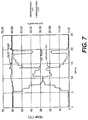
Die Anzahl von betroffenen Bauelementen steht ebenfalls exponentiell mit der Temperaturzunahme aus Eigenerwärmung in Beziehung. Wie
Wenn der Sollwert aufrechterhalten werden kann, werden dann alle Bauelemente der am weitesten rechts liegenden Kurve, die im Schwanz rechts von 480 MHz liegen, Hochleistungsbauelemente sein. Wenn jedoch der Sollwert aufgrund von Eigenerwärmung nicht aufrechterhalten werden kann, wird sich dann die Kurve verschieben, was beispielsweise zu der am weitesten links liegenden Kurve führen wird. Bei diesem Beispiel wird angenommen, daß die tatsächliche Übergangstemperatur des Bauelements um 20 Grad C zunimmt, was zu einer Abnahme des Leistungsvermögens um annähernd 4% führen würde. Die Verteilung der Bauelemente in diesem Posten wird deshalb nach links verschoben, so daß sie um annähernd 432 MHz (4% von 450 = 18) zentriert ist. Diese verschobene Kurve ist durch die am weitesten links liegende Kurve dargestellt. Ein Hochleistungsbauelement muß jedoch dennoch eine fmax von 480 MHz oder größer haben. Der Hochleistungsbereich der Kurve hat sich somit weiter in den Schwanz der Verteilung hineinbewegt. Wie es aus der Fläche unter der Kurve deutlich wird, ist nun die Anzahl von Hochleistungsbauelementen exponentiell kleiner.If the set point can be maintained, then all of the rightmost curve components located in the tail to the right of 480 MHz will be high performance devices. However, if the setpoint can not be maintained due to self-heating, then the curve will shift, resulting in, for example, the leftmost curve. In this example, it is assumed that the actual transition temperature of the device increases by 20 degrees C, which would result in a decrease in performance of approximately 4%. The distribution of components in this item is therefore shifted to the left so that it is centered at approximately 432 MHz (4% of 450 = 18). This shifted curve is represented by the leftmost curve. However, a high performance device must still have a f max of 480 MHz or greater. The high power region of the curve has thus moved further into the tail of the distribution. As can be seen from the area under the curve, the number of high performance devices is now exponentially smaller.
Dieses Problem würde fortfahren, noch schlechter zu werden. Die Industrietrends gehen in Richtung von Bauelementen, die bei höheren Frequenzen arbeiten und weniger Fläche einnehmen. Dies bewirkt, daß die Bauelemente mehr Energie verwenden, größere Leistungsspitzen oder -übergänge aufweisen und weniger in der Lage sind, die Wärme, die sie erzeugen, zu dissipieren.This problem would continue to get worse. Industrial trends are moving towards devices that operate at higher frequencies and occupy less space. This causes the devices to use more energy, have larger power peaks or transitions, and be less able to dissipate the heat they generate.
Viele Halbleiter verwenden die Technologie des Komplementär-Metall-Oxid-Halbleiters (”CMOS”). Eine der Eigenschaften von CMOS ist, daß diese eine große Leistungsspitze zieht, wenn sie Zustände schaltet. Wenn ein CMOS-Bauelement mit einer schnelleren Geschwindigkeit betrieben wird, wird ferner das Bauelement typischerweise schneller und öfter schalten. Dies wird mehr Energie benötigen und wird auch zu großen, schnellen Änderungen des momentanen Energieverbrauchs führen. Somit wird mehr Wärme erzeugt werden.Many semiconductors use Complementary Metal Oxide Semiconductor ("CMOS") technology. One of the features of CMOS is that it pulls a large power spike when switching states. Further, as a CMOS device operates at a faster speed, typically the device will switch faster and more frequently. This will require more energy and will also result in large, rapid changes in current energy consumption. Thus, more heat will be generated.
Diese Situation wird verschlimmert, indem die Größe und Wärmemasse der Bauelemente verringert wird. Dies führt zu weniger ”Raum”, in den die Wärme des Bauelements dissipieren oder diffundieren kann. Das Nettoergebnis werden größere Schwankungen der DUT-Temperatur aufgrund von Eigenerwärmung und ein zunehmendes Unterbewerten des Leistungsvermögens des DUT sein.This situation is aggravated by reducing the size and thermal mass of the devices. This results in less "space" into which the heat of the device can dissipate or diffuse. The net result will be larger fluctuations in the DUT temperature due to self-heating and increasing underestimation of the performance of the DUT.
Konvektionssysteme haben sich als ineffektiv erwiesen, während Verbesserungen an diesen vorgenommen wurden. In
Während Leitungssysteme einen potentiellen Vorteil gegenüber Konvektionssystemen bieten, haben sie sich auch als uneffektiv erwiesen. In
Eine wirkliche Lösung erfordert eine Fähigkeit, die Temperatur eines DUT schnell zu detektieren, und eine Fähigkeit, schnell und effektiv auf Änderungen der Temperatur des DUT anzusprechen.A real solution requires an ability to quickly detect the temperature of a DUT, and an ability to respond quickly and effectively to changes in the temperature of the DUT.
Wie es in dieser Anmeldung beschrieben wird, werden beide Erfordernisse durch die offenbarte Erfindung angesprochen. Sie liefern einen Mechanismus zum schnellen Bestimmen der Temperatur des DUT, indem eine neu entwickelte Leistungsfolgerückkopplungstechnik verwendet wird. Die Offenbarungen stellen auch eine Wärmequelle/senke bereit (gattungsgemäß einen Wärmetauscher (”Hx”)), der schnell und effektiv ansprechen kann, um die Eigenerwärmung des DUT auszugleichen. In
Das Leistungsfolgerückkopplungsverfahren, das zum Bestimmen der Temperatur des DUT verwendet wird, hat auch den Vorteil, daß es in Echtzeit arbeitet, so daß Prüfabfolgen optimiert werden können, ohne die Notwendigkeit eine thermische Konditionierung zu verändern, und ohne daß die thermische Konditionierung die Prüfprogrammflexibilität begrenzt. Ein Schlüsselmerkmal ist die Entwicklung und Verwendung einer einfachen Gleichung, die die Ableitung einer Temperatur des DUT aus den Leistungsmessungen erlaubt.The power train feedback method used to determine the temperature of the DUT also has the advantage that it operates in real time so that test sequences can be optimized without the need to alter thermal conditioning and without thermal conditioning limiting test program flexibility. A key feature is the development and use of a simple equation that allows the derivation of a temperature of the DUT from the power measurements.
Während eine Messung, die auch eine Berechnung genannt wird, des gesamten Leistungsgebrauchs eines DUT erwünscht ist, wird Fachleuten auf dem betreffenden Gebiet im Lichte der vorliegenden Offenbarung klar werden, daß dies nicht immer notwendig sein wird. Es ist klar, daß es Ausführungsformen geben wird, in denen ein Teil der Leistung abgeschätzt oder ignoriert werden könnte. Dies kann beispielsweise und ohne Beschränkung auftreten, wenn alle Leistungsfluktuationen des Bauelements auf eine besondere Spannung oder Stromversorgung isoliert sind, oder wenn eine besondere Stromversorgung dem Bauelement eine vergleichsweise geringe Menge an Energie liefert.While a measurement, also called a calculation, of the total power usage of a DUT is desired, it will be apparent to those skilled in the art, in light of the present disclosure, that this will not always be necessary. It will be understood that there will be embodiments in which some of the power could be estimated or ignored. This may occur, for example and without limitation, when all power fluctuations of the device are isolated to a particular voltage or power supply, or when a particular power supply provides the device with a comparatively small amount of power.
Ferner ist die Überwachung der Stromversorgungen ein geeignetes Verfahren einer Überwachung des Leistungsgebrauchs, da die Verbindungen von dem DUT entfernt werden, und da sie die momentanen Leistungsfluktuationen erfasst, bevor die tatsächliche Änderung der Eigenerwärmung auftritt. Es ist anzumerken, daß diese Leistungsfluktuationen Zunahmen oder Abnahmen sein können, und Zunahmen oder Abnahmen der Eigenerwärmung hervorrufen können. Fachleute werden jedoch feststellen, daß es andere Verfahren einer Überwachung von Leistung, Strom und/oder Spannung gibt.Furthermore, the monitoring of the power supplies is a suitable method of monitoring the power usage as the connections are removed from the DUT, and since it detects the instantaneous power fluctuations before the actual change in self-heating occurs. It should be noted that these performance fluctuations may be increases or decreases, and may cause increases or decreases in self-heating. However, those skilled in the art will recognize that there are other methods of monitoring power, current and / or voltage.
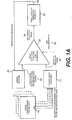
2. Leistungsfolgesystem2. Performance Sequence System
Auf der Grundlage einer gegebenen Chip-Solltemperatur oder eines Signals, das die Solltemperatur
Nach
Die zweite Präzisionskonstantstromquelle
Wie der Fachmann im Lichte der vorliegenden und mit eingeschlossenen Offenbarungen leicht feststellen wird, können die Funktionen des Gesamtsystems mit einer Vielfalt von Techniken ausgeführt werden. Hierin sind elektrische Schaltungen für die Überwachungsschaltung und die Wärmeregelungsschaltung offenbart, jedoch sind andere Ausführungsarten für diese Funktionen möglich, ebenso wie für andere, wie beispielsweise die Erzeugung der Signale, die den Strom, die Spannung, die Temperatur und die Leistung darstellen.As those skilled in the art will readily appreciate in light of the present and including disclosures, the functions of the overall system may be performed by a variety of techniques. Herein, electrical circuits for the monitoring circuit and the thermal control circuit are disclosed, but other embodiments are possible for these functions as well as for others such as the generation of the signals representing the current, voltage, temperature and power.
Gemäß einem Aspekt der vorliegenden Erfindung kann die hierin offenbarte Funktionalität durch Hardware, Software und/oder einer Kombination von beiden ausgeführt sein. Software-Ausführungen können in irgendeiner geeigneten Sprache geschrieben sein, die ohne Beschränkung hohe Programmiersprachen, wie beispielsweise C++, mittlere und niedrige Sprachen, Assemblersprachen und anwendungsspezifische oder gerätespezifische Sprachen einschließen. Derartige Software kann auf einem Mehrzweckcomputer, wie einem 486 oder einem Pentium, einem anwendungsspezifischen Hardware-Teil oder einer anderen geeigneten Einrichtung laufen gelassen werden.In accordance with one aspect of the present invention, the functionality disclosed herein may be implemented by hardware, software, and / or a combination of both. Software implementations may be written in any suitable language including, without limitation, high-level programming languages such as C ++, middle and lower languages, assembly languages, and application-specific or device-specific languages. Such software may be run on a general purpose computer, such as a 486 or Pentium, an application specific hardware part, or other suitable device.
Zusätzlich zur Verwendung diskreter Hardware-Bauteile in einer logischen Schaltung, kann die erforderliche Logik auch durch eine anwendungsspezifische integrierte Schaltung (”ASIC”) oder andere Einrichtung ausgeführt sein. Die Technik kann eine analoge Schaltung, digitale Schaltung oder eine Kombination von beiden verwenden. Das System wird auch verschiedene Hardware-Bauteile umfassen, die in der Technik allgemein bekannt sind, wie beispielsweise Verbinder, Kabel und dergleichen. Außerdem kann zumindest ein Teil dieser Funktionalität in computerlesbaren Medien ausgeführt sein (die auch als Computerprogrammprodukte bezeichnet werden), wie beispielsweise magnetische, magnetisch-optische und optische Medien, die beim Programmieren einer Informationsverarbeitungsvorrichtung verwendet werden, um gemäß der Erfindung zu arbeiten. Diese Funktionalität kann auch in computerlesbaren Medien oder Computerprogrammprodukten ausgeführt sein, wie beispielsweise eine gesendete Wellenform, die beim Senden der Information oder Funktionalität verwendet werden soll.In addition to using discrete hardware components in a logic circuit, the required logic may also be implemented by an application specific integrated circuit ("ASIC") or other means. The technique may use an analog circuit, digital circuit, or a combination of both. The system will also include various hardware components that are well known in the art, such as connectors, cables, and the like. In addition, at least some of this functionality may be embodied in computer readable media (also referred to as computer program products), such as magnetic, magneto-optical, and optical media used in programming an information processing device to operate in accordance with the invention. This functionality may also be embodied in computer readable media or computer program products, such as a transmitted waveform to be used in transmitting the information or functionality.
Ferner sollte die vorliegende Offenbarung es dem Fachmann klar machen, daß die vorliegende Erfindung auf einer Vielfalt von unterschiedlichen Gebieten, Anwendungen, Industrien und Technologien angewandt werden kann. Die vorliegende Erfindung kann ohne Beschränkung mit irgendeinem mit Energie beaufschlagten System verwendet werden, indem die Temperatur entweder überwacht oder geregelt werden muß. Dies kann ohne Beschränkung viele unterschiedliche Prozesse und Anwendungen umfassen, die mit der Halbleiterherstellung, -prüfung und -betrieb zu tun haben.Further, the present disclosure should make it clear to those skilled in the art that the present invention can be applied to a variety of different fields, applications, industries, and technologies. The present invention may be used without limitation with any energized system by either monitoring or controlling the temperature. This may include, without limitation, many different processes and applications related to semiconductor manufacturing, testing, and operation.
Zusätzlich berechnet oder überwacht die bevorzugte Ausführungsform die Leistung, die einem DUT von einer Stromversorgung zugeführt wird. Diese Leistung wird typischerweise zu einer Leistungsebene oder -gitter von irgendeiner Art an den DUT über eine oder mehrere Leistungsverbindungen in dem DUT geliefert. Dies muß von der Leistung unterschieden werden, die in irgendeinem Signal inhärent ist. Es ist klar, daß jede Signalverbindung an einem Bauelement dafür entworfen ist, die spezifizierte Leistung dieses Signals zu empfangen, beispielsweise ein Taktsignal. Jedoch ist die Leistung, die die bevorzugte Ausführungsform überwacht, die Leistung, die von einer Stromversorgung den Leistungsverbindungen geliefert wird, und nicht die Leistung, die in einem Signal inhärent ist, das einer Signalverbindung zugeführt werden könnte. Eine Stromversorgung, wie sie oben verwendet wird, bezieht sich auf eine normale Industrieeinrichtung, die elektrische Energie mit einer festgelegten Spannung zum Betrieb eines Bauelements zuführen kann. Es sollte jedoch klar sein, daß die Techniken der vorliegenden Erfindung auf jedes Signal angewandt werden könnten, das ohne Beschränkung ein Leistungssignal, ein Taktsignal und ein Datensignal umfaßt. Diese Techniken könnten auch auf nicht standardmäßige Stromversorgungen angewandt werden.In addition, the preferred embodiment calculates or monitors the power supplied to a DUT from a power supply. This power is typically provided to a power level or grid of some sort at the DUT via one or more power connections in the DUT. This must be distinguished from the power inherent in any signal. It will be understood that each signal connection on a device is designed to receive the specified power of that signal, for example a clock signal. However, the power that the preferred embodiment monitors is the power supplied by a power supply to the power links rather than the power inherent in a signal that could be applied to a signal connection. A power supply, as used above, refers to a normal industrial equipment that can supply electrical energy at a fixed voltage for operation of a device. It should be understood, however, that the techniques of the present invention could be applied to any signal including, without limitation, a power signal, a clock signal, and a data signal. These techniques could also be applied to non-standard power supplies.
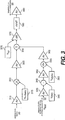
3. Die Summierfunktion der Überwachungsschaltung3. The summation function of the monitoring circuit
Die thermischen Bauteile des Systems sprechen langsamer (z. B. Millisekunden) an, als es die dem elektronischen Prüfling zugeführte Leistung tut (z. B. Nanosekunden). Dementsprechend fügen die Hochfrequenzanteile der Strom- und Spannungssignale
Die Strom- und Spannungssignale
Für jede Stromversorgung verwendet die Überwachungsschaltung
- – P = Leistungsgebrauch in Watt
- – I = Stromsignal in Ampere
- – V = Spannungssignal in Volt
- - P = power consumption in watts
- - I = current signal in amperes
- - V = voltage signal in volts
Wenn die Stromversorgung
Der Skalierfaktor kann auch empirisch mit dieser Formel bestimmt werden:
Dies könnte vorgenommen werden, indem der tatsächliche Strom und die Signalspannung gleichzeitig gemessen werden und dann die Spannung durch die gemessene Stromstärke dividiert wird. Bestimmte Ausführungsformen können auch die Einstellung von einem oder mehreren besonderen Stromausgängen und dann das Messen der Signalspannung(en) zulassen.This could be done by measuring the actual current and signal voltage simultaneously and then dividing the voltage by the measured current. Certain embodiments may also allow the adjustment of one or more particular power outputs and then measuring the signal voltage (s).
Der Ausgang von all den ersten Multiplikationsschaltungen
4. Die Wärmeregelungsschaltung4. The thermal control circuit
- – Chip-Temperatur (°C) stellt die Chip-Temperatur dar, die aus seiner Energiedissipation abgeleitet wird.
- – Ktheta ist eine Konstante (°C/Watt), die aus den Fähigkeiten des Temperaturerzwingungssystems und des Wärmewiderstandes des Mediums (oder Medien in den Fällen, in denen Wärme-Ausbreiter, Deckel oder andere Bauelemente an der Oberseite des Bauelements selbst angebracht sind), zwischen dem elektronischen Bauelement und dem Wärmetaucher abgeleitet wird.
- – Ped (Watt) ist der Gesamtleistungsgebrauch, der in
dem Leistungsgebrauchssignal 20 widerspiegelt wird, das aus der Überwachungsschaltung10 erhalten wird (siehe1A ). - – Tfss (°C) ist die Erzwingungstemperatur der Systemoberfläche und die absolute Temperatur des den Chip kontaktierenden Mediums, wie von einem Temperatursensor gemessen, der in die Wärmeregelungssystemoberfläche eingebettet ist.
- - Chip temperature (° C) represents the chip temperature derived from its energy dissipation.
- K theta is a constant (° C / watt), which is made up of the capabilities of the temperature forcing system and the thermal resistance of the medium (or media in cases where heat spreaders, lids or other components are attached to the top of the component itself) , is derived between the electronic component and the heat exchanger.
- - P ed (Watts) is the total power used in the
power usage signal 20 is reflected from themonitoring circuit 10 is obtained (see1A ). - - T fss (° C) is the surface temperature of the system surface and the absolute temperature of the chip contacting medium, as measured by a temperature sensor embedded in the thermal control system surface.
Ktheta wird auch aus dem allgemeinen Wirkungsgrad des Wärmeregelungssystems abgeleitet, wenn dieses in Kontakt mit dem DUT steht. Beispielsweise verliert der DUT bei Solltemperaturen ziemlich oberhalb der Umgebungstemperatur proportional mehr Wärme an seine Umgebung, und das Wärmeregelungssystem muss härter arbeiten, um die Temperatur des DUT zu erhöhen als um diese zu senken. Vom Standpunkt eines Wärmeregelungssystems aus, das auf Eigenerwärmung des DUT anspricht, ist die Gesamtwirkung gleich wie ein niedrigerer Wärmewiderstand zwischen dem DUT und dem Wärmetauscher, der bei einem Umgebungssollwert arbeitet. Ähnlich gewinnt der DUT bei Solltemperaturen ziemlich unterhalb der Umgebungstemperatur Wärme aus seiner Umgebung, und das Wärmeregelungssystem muss härter arbeiten, um die Temperatur zu senken, als um diese zu erhöhen. Vom Standpunkt eines Wärmeregelungssystems aus, das auf Eigenerwärmung des DUT anspricht, ist die Gesamtwirkung gleich wie ein höherer Wärmewiderstand zwischen dem DUT und dem Wärmetauscher, der bei einem Umgebungssollwert arbeitet. In beiden Fällen wird Ktheta derart eingestellt, dass es die Wirkung einer Wärmeübertragung zu der den DUT umgebenden Umgebung während Leistungsausschlägen widerspiegelt.K theta is also derived from the overall efficiency of the thermal control system when in contact with the DUT. For example, at target temperatures well above ambient, the DUT proportionally loses more heat to its environment, and the thermal control system must work harder to increase the temperature of the DUT than to lower it. From the standpoint of a thermal control system responsive to self-heating of the DUT, the overall effect is the same as a lower thermal resistance between the DUT and the heat exchanger operating at an ambient setpoint. Similarly, at set temperatures well below ambient, the DUT gains heat from its surroundings, and the thermal control system must work harder to lower the temperature than to increase it. From the standpoint of a thermal control system responsive to self-heating of the DUT, the overall effect is the same as a higher thermal resistance between the DUT and the heat exchanger operating at an ambient setpoint. In both cases, K theta is set to reflect the effect of heat transfer to the environment surrounding the DUT during power excursions.
Ktheta kann als ein effektiver oder ein fein abgestimmter Wärmewiderstand des Mediums angesehen werden. Obwohl der Wärmewiderstand von unterschiedlichen Medien in Standardnachschlagewerken der Chemie (wie beispielsweise CRC Handbook of Chemistry and Physics, 77. Ausgabe; David R. Lide, Chefherausgeber), angegeben sind, können Faktoren, wie beispielsweise die Umgebungsfeuchte, Druck und Temperatur den tatsächlichen Wärmewiderstand beeinflussen. Der Wärmewiderstand kann auch durch die physikalische Ausgestaltung der Prüfung beeinflußt werden. Um Ktheta zu bestimmen, kann man einen Kalibrierungsprozeß dazu verwenden, den Wert des vorweggenommenen Wärmewiderstandes des Mediums einzustellen, um festzustellen, ob das Ergebnis eine Verbesserung ist. Ein weiterer Vorteil eines Kalibrierungsprozesses ist, daß er automatisch den ”Wirkungsgradfaktor” der Wärmeübertragung von dem DUT zu dem Wärmeregelungssystem als eine Funktion der Solltemperatur berücksichtigen wird.K theta can be considered as an effective or finely tuned thermal resistance of the medium. Although the thermal resistance of different media is given in standard chemistry references (such as CRC Handbook of Chemistry and Physics, 77th ed., David R. Lide, Chief Editor), factors such as ambient humidity, pressure and temperature can affect actual thermal resistance , The thermal resistance can also be influenced by the physical design of the test. To determine K theta , one can use a calibration process to set the value of the anticipated thermal resistance of the medium to determine if the result is an improvement. Another advantage of a calibration process is that it will automatically take into account the "efficiency factor" of heat transfer from the DUT to the thermal control system as a function of the setpoint temperature.
Wie es oben beschrieben ist, bietet Ktheta den Vorteil eines Einarbeitens der Wirkungen einer Vielfalt von Variablen in einen einzigen Term. Bei der bevorzugten Ausführungsform braucht Ktheta nur für eine gegebene Anwendung oder einen gegebenen Typ eines DUT optimiert werden, und kann dazu verwendet werden, viele unterschiedliche Bauelemente des gleichen Typs zu prüfen. Zusätzlich ist eine praktische Wirkung von Ktheta, das beim Spiegeln des überwachten Energieverbrauches des Bauelements mit der Temperatur des Temperaturerzwingungssystems (siehe
In der Wärmesummierschaltung
- – Vtcs ist das Temperaturregelungssignal.
- – Vsp
ist eine Solltemperaturspannung 375 , eine Spannung, die die Solltemperatur für das elektronische Bauelement darstellt. - – Vk-theta
ist eine Spannung 315 , die den Ktheta-Wert darstellt. Der Ktheta-Wert wird in einen Digital/Analog-Wandler eingegeben, der eine Spannung erzeugt, die dem Wert der Eingabe entspricht. - – VPed
ist das Gesamtleistungsgebrauchssignal 20 , dasvon der Überwachungsschaltung 10 erhalten wird (siehe1A ) und das die durch den DUT verbrauchten Watt darstellt. - – Vfsst ist die
Temperaturspannung der Erzwingungssystemoberfläche 32 , die durch Digital/Analog-Wandlung erzeugt wird und die Temperatur der Erzwingungssystemoberfläche darstellt. - –
V IRO345 ist eine Spannung, die durch Digital/Analogwandlung erzeugt wird, welche eine Spannung darstellt, die gleich dem Wert des präzisen konstanten Stromes von der ersten Präzisionskonstantstromquelle28 inder Wärmeregelungsplatine 27 multipliziert mit dem Widerstand, der durch die Einrichtung mit variablem Widerstandim Wärmetauscher bei 0 Grad C gezeigt wird, ist. Diese kann bestimmt werden, wenn der eingebettete Temperatursensor im Wärmetauscher kalibriert wird. - –
V alpha360 ist eine Spannung, die durch Digital/Analog-Wandlung erzeugt wird und die Steigung einer Kurve für die Einrichtung mit variablem Widerstand in dem Wärmetauscher von Widerstand über Temperatur darstellt. Diese kann bestimmt werden, wenn der eingebettete Temperatursensor in dem Wärmetauscher kalibriert wird.
- - V tcs is the temperature control signal .
- - V sp is a
setpoint temperature voltage 375 , a voltage representing the target temperature for the electronic component. - - V k-theta is a
voltage 315 representing the K theta value. The K theta value is input to a digital-to-analog converter which generates a voltage corresponding to the value of the input. - - V Ped is the
total power usage signal20 that from themonitoring circuit 10 is obtained (see1A ) representing the watts consumed by the DUT. - V fsst is the temperature voltage of the
enforcement system surface32 which is generated by digital-to-analog conversion and represents the temperature of the enforcement system surface. - -
V IRO345 is a voltage generated by digital / analog conversion representing a voltage equal to the value of the precise constant current from the first precision constantcurrent source 28 in thethermal control board 27 multiplied by the resistance shown by the variable resistance device in the heat exchanger at 0 degrees C. This can be determined if the embedded temperature sensor is calibrated in the heat exchanger. - -
V alpha360 is a voltage generated by digital-to-analog conversion that represents the slope of a curve for the variable resistance device in the heat exchanger over temperature heat exchanger. This can be determined when the embedded temperature sensor in the heat exchanger is calibrated.
Nach
Das resultierende Signal tritt dann in eine Ableitungsschaltung
Die Ableitungsschaltung
Andere Ausführungsformen können eine richtige PID-Regelung verwenden, indem beispielsweise entweder ein Kundensystem entworfen wird, oder indem ein kommerzieller Standard-Servo-Kontroller verwendet wird. Ein derartiges System fügt Fähigkeiten hinzu, wie kontinuierliche Rampenbildung, S-Kurven-Profilgebung, Servo-Abstimmung für minimales Überschwingen und Unterschwingen und verbesserte Stabilität der Regelung. Abhängig von dem besonderen verwendeten Kontroller kann es sein, daß der PID-Kontroller die Temperatursignale und das Leistungssignal in irgendeine Art von Wärmepositionssignal umwandeln und es zurück in einen kommerziellen Servomotor-Kontroller koppeln muß. Es kann sein, daß einige Kontroller auch eine gewisse Umwandlung am hinteren Ende benötigen. Wie es diese Beispiele zeigen, können die erforderlichen Regelungsfunktionen durch analoge und/oder digitale Schaltungen durchgeführt werden.Other embodiments may use proper PID control, for example by designing either a customer system or by using a standard commercial servo controller. Such a system adds capabilities such as continuous ramping, S-curve profiling, servo tuning for minimum overshoot and undershoot, and improved control stability. Depending on the particular controller used, the PID controller may need to convert the temperature signals and the power signal into some type of heat position signal and couple it back into a commercial servo motor controller. It may be that some controllers also require some rear end conversion. As these examples show, the required control functions can be performed by analog and / or digital circuits.
5. Graphisches Beispiel5. Graphical example
6. Prüfungssteuerung und Temperaturbestimmung6. Test control and temperature determination
Wie es in der Offenbarung beschrieben ist, hält ein Regelungssystem die Temperatur des DUT innerhalb einer gegebenen Toleranz auf einem festgelegten Sollwert. Das Regelungssystem muß deshalb gewisse Information über die Temperatur des DUT haben. Einige Regelungssysteme, wie beispielsweise direkte Temperaturfolge, erfordern eine wiederholte DUT-Temperaturinformation. Andere Regelungssysteme, wie beispielsweise Leistungsfolge, die eine Abweichung von einem Sollwert regeln, benötigen keine wiederholte DUT-Temperaturinformation, sondern müssen nur wissen, wann der Temperaturaufrechterhaltungsprozeß beginnen soll.As described in the disclosure, a control system maintains the temperature of the DUT within a given tolerance at a predetermined set point. The control system must therefore have some information about the temperature of the DUT. Some control systems, such as direct temperature sequence, require repeated DUT temperature information. Other control systems, such as power trains that control deviation from a set point, do not require repeated DUT temperature information, but only need to know when to begin the temperature maintenance process.
Bei einer Ausführungsform beginnt der Leistungsfolgeprozeß, nachdem der DUT die Solltemperatur erreicht hat. Diese Information kann indirekt bestimmt werden, beispielsweise nachdem ein Durchwärmungszeitglied abgelaufen ist. Sie kann auch direkt bestimmt werden, beispielsweise indem eine Wärmestruktur überwacht wird. Wärmestrukturen können dazu verwendet werden, eine anfängliche DUT-Temperaturinformation zuzuführen, und sie können auch während der ganzen Prüfung überwacht werden, wenn sie geeignet kalibriert sind. Eine Ausführungsform der vorliegenden Erfindung überwacht Wärmestrukturen, um die Anfangstemperatur des DUT zu bestimmen, bevor ein Leistungsfolgetemperaturregelungsverfahren eingeleitet wird.In one embodiment, the power-on process begins after the DUT has reached the setpoint temperature. This information can be determined indirectly, for example, after a warm-up timer has expired. It can also be determined directly, for example by monitoring a thermal structure. Thermal structures may be used to provide initial DUT temperature information, and may also be monitored throughout the test if properly calibrated. An embodiment of the present invention monitors heat structures to determine the initial temperature of the DUT before initiating a power sequence temperature control process.
Der Kennzeichnungs- und Validierungsprozeß wird vorzugsweise für die Leistungsfolgetemperaturregelung eines besonderen Typs von DUT durchgeführt. Dieser Prozeß verwendet die Temperaturinformation. Wenn eine statistisch relevante Probe mit einer wahren Die-Temperaturinformation während des Kalibrierungsprozesses genommen wird, ist dann keine Temperaturerfassungseinrichtung in dem Die während der Herstellung und Prüfung mit hohem Volumen notwendig.The labeling and validation process is preferably performed for the power sequence temperature control of a particular type of DUT. This process uses the temperature information. If a statistically relevant sample is taken with true die temperature information during the calibration process, then no temperature detector in the die is necessary during high volume manufacturing and testing.
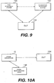
Ausführungsformen der vorliegenden Erfindung können separate Regelungsabschnitte umfassen, um die Temperatur zu regeln und die Prüfabfolge zu steuern. In
Diese beiden Steuerungssysteme
7. Datenbeschaffung7. Data collection
Die Information, die das oben beschriebene Leistungsfolgesystem verwendet, ist Information über den Leistungszug eines DUT. Bei einer beschriebenen Ausführungsform ist diese Information das skalierte Spannungsabbild von Strom- und Spannungssignalen, wie dies in
In
Nach
Die Datenbeschaffungskarte
Die Datenbeschaffungskarte
Der PC
Bei einer bevorzugten Ausführungsform beschafft die Datenbeschaffungskarte
8. Temperaturregelungseinheit8. Temperature control unit
Der Wärmetauscher
Die Heizung des Wärmetauschers
Beim Diskutieren der Temperatur einer Heizung oder Wärmesenke oder anderen Einrichtung ist einzusehen, daß die Temperatur eines einzelnen Punktes an dem Bauelement diskutiert wird. Dies folgt aus der Tatsache, daß eine typische Heizung oder Wärmesenke oder andere Einrichtung einen Temperaturgradienten über die Oberfläche hinweg aufweisen wird. Im Fall einer Heizung erfolgt die Anwesenheit eines Gradienten zum Teil aufgrund der Tatsache, daß das Heizelement gewöhnlich nur einen Teil der Heizung einnimmt.In discussing the temperature of a heater or heat sink or other device, it will be understood that the temperature of a single point on the device is discussed. This follows from the fact that a typical heater or heat sink or other device will have a temperature gradient across the surface. In the case of heating, the presence of a gradient is due in part to the fact that the heating element usually occupies only part of the heating.
Das Flüssigkeitskühlungs- und -rezirkulationssystem
Ein Prüfkopf
9. Modifikationen und Vorzüge9. Modifications and Benefits
Ausführungsformen der vorliegenden Erfindung können eine Zeitverzögerung oder Filterung bei dem Leistungsgebrauchssignals
Andere Ausführungsformen können auch eine große Bypass-Kapazität an einer Prüfgerät-Schnittstellenplatine oder einem DUT selbst kompensieren. Eine Bypass-Kapazität wird dazu verwendet, eine momentane Ladung zuzuführen, die die Stromversorgung aufgrund von induktiver Belastung oder physikalischer Entfernung nicht schnell genug auffüllen kann. Wenn die Bypass-Kapazität zunimmt, wird die Zeit zwischen dem Leistungszufuhrsignal und der Eigenerwärmung des DUT abnehmen.Other embodiments may also compensate for large bypass capacitance on a tester interface board or DUT itself. A bypass capacitance is used to supply a momentary charge that can not fill up the power supply quickly enough due to inductive load or physical distance. As the bypass capacitance increases, the time between the power supply signal and the self-heating of the DUT will decrease.
Während die oben beschriebene Ausführungsform analoge Konstruktionstechniken verwendet, könnten bei einer alternativen Ausführungsform der Erfindung ein digitaler Signalprozessor und Software verwendet werden, um dies digital zu bewirken.While the embodiment described above uses analog design techniques, in an alternative embodiment of the invention, a digital signal processor and software could be used to do so digitally.
Die Vorzüge der vorliegenden Erfindung umfassen, dass eine Vorrichtung und ein Verfahren einer Temperaturregelung für elektronische Bauelemente bereitgestellt werden, die auf die Temperatur des elektronischen Bauelements anstelle der Verpackung ansprechen können. Ein weiterer Vorzug der vorliegenden Erfindung ist, daß sie eine Vorrichtung und ein Verfahren einer Temperaturregelung für elektronische Bauelemente bereitstellt, die geeignet zur Chip-Herstellung mit hohem Volumen verwendet werden können. Ein weiterer Vorzug der vorliegenden Erfindung ist, daß sie eine Vorrichtung und ein Verfahren einer Temperaturregelung für elektronische Bauelemente bereitstellt, das zuverlässig ist.The benefits of the present invention include providing an apparatus and method for temperature control for electronic components that are responsive to the temperature of the electronic component rather than the packaging. Another advantage of the present invention is that it provides an electronic device temperature control apparatus and method that can be suitably used for high volume chip fabrication. Another advantage of the present invention is that it provides an apparatus and method of electronic component temperature control that is reliable.
Ein weiterer Vorzug der vorliegenden Erfindung ist, dass sie eine Vorrichtung und ein Verfahren einer Temperaturregelung für ein elektronisches Bauelement bereitstellt, das keine wesentliche Oberfläche des elektronischen Bauelements benötigt, um die Bauelementtemperatur zu erfassen, obwohl das System Oberfläche zur Leitung benötigt. Ein weiterer Vorzug der vorliegenden Erfindung ist, daß sie die Notwendigkeit beseitigt, daß Temperaturerfassungseinrichtungen in den Chip integriert werden oder temporär mit dem Chip verbunden werden müssen.Another advantage of the present invention is that it provides a device and method of temperature control for an electronic device that does not require a substantial surface area of the electronic device to detect the device temperature, although the system requires surface area for conduction. Another advantage of the present invention is that it eliminates the need for temperature sensing devices to be integrated into the chip or temporarily connected to the chip.
Noch ein anderer Vorzug ist, dass die vorliegende Erfindung auch die Notwendigkeit zum Sammeln, Aufrechterhalten und Anwenden der Verwendung von Chip-Leistungsprofilen beseitigt, sowie die Notwendigkeit für die Fähigkeit beseitigt, in der automatisierten Prüfausrüstung, Temperaturerzwingungssystem und Prüfsoftware, Chip-Leistungsprofile zu sammeln und anzuwenden.Yet another advantage is that the present invention also eliminates the need to collect, maintain and apply the use of chip power profiles, as well as eliminate the need for the ability to collect chip performance profiles in the automated test equipment, temperature enforcement system and testing software apply.
Die Prinzipien, bevorzugten Ausführungsformen und Betriebsmodi der vorliegenden Erfindung sind in der vorstehenden Beschreibung beschrieben worden. Die Erfindung ist nicht als auf die besonderen offenbarten Formen begrenzt anzusehen, da diese als vielmehr veranschaulichend denn als beschränkend anzusehen sind.The principles, preferred embodiments and modes of operation of the present invention have been described in the foregoing specification. The invention is not to be regarded as limited to the particular forms disclosed, as these are to be regarded as illustrative rather than restrictive.
Claims (24)
Applications Claiming Priority (3)
| Application Number | Priority Date | Filing Date | Title |
|---|---|---|---|
| US9272098P | 1998-07-14 | 1998-07-14 | |
| US60/092,720 | 1998-07-14 | ||
| PCT/US1999/015846 WO2000004582A1 (en) | 1998-07-14 | 1999-07-14 | Temperature control of electronic devices using power following feedback |
Publications (2)
| Publication Number | Publication Date |
|---|---|
| DE19983379T1 DE19983379T1 (en) | 2001-09-13 |
| DE19983379B4 true DE19983379B4 (en) | 2011-08-18 |
Family
ID=22234752
Family Applications (1)
| Application Number | Title | Priority Date | Filing Date |
|---|---|---|---|
| DE19983379T Expired - Lifetime DE19983379B4 (en) | 1998-07-14 | 1999-07-14 | Temperature control of electronic devices using power train feedback |
Country Status (5)
| Country | Link |
|---|---|
| JP (1) | JP4703850B2 (en) |
| KR (1) | KR100755295B1 (en) |
| AU (1) | AU4991799A (en) |
| DE (1) | DE19983379B4 (en) |
| WO (1) | WO2000004582A1 (en) |
Cited By (1)
| Publication number | Priority date | Publication date | Assignee | Title |
|---|---|---|---|---|
| EP2866255A3 (en) * | 2013-10-28 | 2015-08-05 | General Electric Company | System and method for enhanced convection cooling of temperature-dependent power producing and power consuming electrical devices |
Families Citing this family (8)
| Publication number | Priority date | Publication date | Assignee | Title |
|---|---|---|---|---|
| US6794620B1 (en) * | 2001-11-07 | 2004-09-21 | Advanced Micro Devices, Inc. | Feedforward temperature control of device under test |
| DE10203790A1 (en) * | 2002-01-31 | 2003-06-26 | Siemens Ag | Method for operating a semiconductor component avoids temperature fluctuations by actively boosting temperature under low electrical load so as to match temperature level to that under high load |
| US6825681B2 (en) | 2002-07-19 | 2004-11-30 | Delta Design, Inc. | Thermal control of a DUT using a thermal control substrate |
| US7313500B2 (en) | 2004-11-05 | 2007-12-25 | Schweitzer Engineering Labortories, Inc. | Method to increase the maximum allowable ambient temperature rating of an electronic device |
| DE102005001163B3 (en) | 2005-01-10 | 2006-05-18 | Erich Reitinger | Semiconductor wafers` testing method, involves testing wafer by probes, and reducing heating energy with constant cooling efficiency, under consideration of detected increase of temperature of fluids flowing via tempered chuck device |
| US10514416B2 (en) | 2017-09-29 | 2019-12-24 | Advantest Corporation | Electronic component handling apparatus and electronic component testing apparatus |
| CN109932630B (en) * | 2017-12-15 | 2021-08-03 | 朋程科技股份有限公司 | Over-temperature detection circuit and testing method thereof |
| JP7266481B2 (en) * | 2019-07-19 | 2023-04-28 | 東京エレクトロン株式会社 | Temperature control device, temperature control method, and inspection device |
Citations (2)
| Publication number | Priority date | Publication date | Assignee | Title |
|---|---|---|---|---|
| US4881591A (en) * | 1985-09-23 | 1989-11-21 | Sharetree Limited | Oven for the burn-in of integrated circuits |
| EP0837335A1 (en) * | 1996-10-21 | 1998-04-22 | Schlumberger Technologies, Inc. | Method and apparatus for temperature control of a device during testing |
Family Cites Families (10)
| Publication number | Priority date | Publication date | Assignee | Title |
|---|---|---|---|---|
| US4330809A (en) * | 1979-12-31 | 1982-05-18 | Crown International, Inc. | Thermal protection circuit for the die of a transistor |
| US4637020A (en) * | 1983-08-01 | 1987-01-13 | Fairchild Semiconductor Corporation | Method and apparatus for monitoring automated testing of electronic circuits |
| US4686627A (en) * | 1984-12-24 | 1987-08-11 | Honeywell Inc. | Electrical test apparatus |
| DE3536098A1 (en) * | 1985-10-09 | 1987-04-09 | Siemens Ag | Device for monitoring the temperature of an electrical component |
| US4713612A (en) * | 1986-07-14 | 1987-12-15 | Hughes Aircraft Company | Method and apparatus for determination of junction-to-case thermal resistance for a hybrid circuit element |
| US5324916A (en) * | 1991-11-01 | 1994-06-28 | Hewlett-Packard Company | System and method for dynamic power compensation |
| US5287292A (en) * | 1992-10-16 | 1994-02-15 | Picopower Technology, Inc. | Heat regulator for integrated circuits |
| JPH07263526A (en) * | 1994-03-17 | 1995-10-13 | Hitachi Ltd | Method of cooling wafer chuck and semiconductor device |
| JP2986381B2 (en) * | 1994-08-16 | 1999-12-06 | インターナショナル・ビジネス・マシーンズ・コーポレイション | Electronic chip temperature control device and method |
| JPH09264647A (en) * | 1996-03-27 | 1997-10-07 | Nec Corp | Electronic apparatus cooling circuit |
-
1999
- 1999-07-14 DE DE19983379T patent/DE19983379B4/en not_active Expired - Lifetime
- 1999-07-14 WO PCT/US1999/015846 patent/WO2000004582A1/en active Application Filing
- 1999-07-14 AU AU49917/99A patent/AU4991799A/en not_active Abandoned
- 1999-07-14 KR KR1020017000633A patent/KR100755295B1/en not_active IP Right Cessation
- 1999-07-14 JP JP2000560611A patent/JP4703850B2/en not_active Expired - Lifetime
Patent Citations (2)
| Publication number | Priority date | Publication date | Assignee | Title |
|---|---|---|---|---|
| US4881591A (en) * | 1985-09-23 | 1989-11-21 | Sharetree Limited | Oven for the burn-in of integrated circuits |
| EP0837335A1 (en) * | 1996-10-21 | 1998-04-22 | Schlumberger Technologies, Inc. | Method and apparatus for temperature control of a device during testing |
Cited By (2)
| Publication number | Priority date | Publication date | Assignee | Title |
|---|---|---|---|---|
| EP2866255A3 (en) * | 2013-10-28 | 2015-08-05 | General Electric Company | System and method for enhanced convection cooling of temperature-dependent power producing and power consuming electrical devices |
| US9570643B2 (en) | 2013-10-28 | 2017-02-14 | General Electric Company | System and method for enhanced convection cooling of temperature-dependent power producing and power consuming electrical devices |
Also Published As
| Publication number | Publication date |
|---|---|
| JP2002520630A (en) | 2002-07-09 |
| WO2000004582A8 (en) | 2000-05-18 |
| WO2000004582A9 (en) | 2000-07-20 |
| JP4703850B2 (en) | 2011-06-15 |
| KR100755295B1 (en) | 2007-09-05 |
| KR20010071917A (en) | 2001-07-31 |
| DE19983379T1 (en) | 2001-09-13 |
| AU4991799A (en) | 2000-02-07 |
| WO2000004582A1 (en) | 2000-01-27 |
Similar Documents
| Publication | Publication Date | Title |
|---|---|---|
| US6489793B2 (en) | Temperature control of electronic devices using power following feedback | |
| DE69531329T2 (en) | Method and apparatus for measuring the thermal impedance of integrated semiconductor components | |
| US6518782B1 (en) | Active power monitoring using externally located current sensors | |
| DE112005000386B4 (en) | Dual control system for maintaining the temperature of an IC chip near a setpoint | |
| DE112005000186B4 (en) | Self-heated thermistor control circuit | |
| DE3841637C1 (en) | ||
| DE202007019290U1 (en) | sensor adapters | |
| DE19983379B4 (en) | Temperature control of electronic devices using power train feedback | |
| DE69915316T2 (en) | TEMPERATURE STABILIZATION OF PERMANENT MAGNETIC ARRANGEMENTS IN A DEVICE OF IMAGING MAGNETIC RESONANCE | |
| DE102013108819A1 (en) | Radiation analyzer and method for radiation analysis | |
| DE4100318A1 (en) | METHOD AND CIRCUIT FOR HIGH-FREQUENCY VOLTAGE / CURRENT MEASUREMENT | |
| DE102010026992A1 (en) | Temperature measurement using a diode with saturation current compensation | |
| DE3419694A1 (en) | ELECTRONIC DEVICE | |
| DE10254222B4 (en) | Fluid-flow-rate arrangement | |
| DE3511144C2 (en) | ||
| EP0955524A2 (en) | Mass air flow sensor | |
| DE202007019316U1 (en) | Temperature Sensor Adapters | |
| DE19920401A1 (en) | Temperature measurement arrangement for electronic device mounted on rigid element | |
| DE3346563A1 (en) | METHOD AND DEVICE FOR MONITORING AND CONTROLLING AN EVAPORATOR | |
| DE102019208079B4 (en) | Electronic device | |
| DE19846917B4 (en) | Method and device for measuring the flow velocity of a fluid | |
| DE102016222941A1 (en) | Method and device for determining the electrical resistance of a thermoelectric module | |
| DE10332540B3 (en) | Method for temperature measurement and device for carrying out the method | |
| WO2023194322A1 (en) | Power supply and method for operating a power supply | |
| WO2002059588A1 (en) | Device and method for measuring a thermal conductivity |
Legal Events
| Date | Code | Title | Description |
|---|---|---|---|
| 8127 | New person/name/address of the applicant |
Owner name: DELTA DESIGN,INC., POWAY, CALIF., US |
|
| 8110 | Request for examination paragraph 44 | ||
| R018 | Grant decision by examination section/examining division | ||
| R020 | Patent grant now final |
Effective date: 20111119 |
|
| R071 | Expiry of right |