DE202010012449U1 - Nozzle arrangement for a spray gun, in particular for a paint spray gun - Google Patents
Nozzle arrangement for a spray gun, in particular for a paint spray gun Download PDFInfo
- Publication number
- DE202010012449U1 DE202010012449U1 DE202010012449U DE202010012449U DE202010012449U1 DE 202010012449 U1 DE202010012449 U1 DE 202010012449U1 DE 202010012449 U DE202010012449 U DE 202010012449U DE 202010012449 U DE202010012449 U DE 202010012449U DE 202010012449 U1 DE202010012449 U1 DE 202010012449U1
- Authority
- DE
- Germany
- Prior art keywords
- nozzle arrangement
- air
- nozzle
- paint
- spray gun
- Prior art date
- Legal status (The legal status is an assumption and is not a legal conclusion. Google has not performed a legal analysis and makes no representation as to the accuracy of the status listed.)
- Expired - Lifetime
Links
Classifications
-
- B—PERFORMING OPERATIONS; TRANSPORTING
- B05—SPRAYING OR ATOMISING IN GENERAL; APPLYING FLUENT MATERIALS TO SURFACES, IN GENERAL
- B05B—SPRAYING APPARATUS; ATOMISING APPARATUS; NOZZLES
- B05B7/00—Spraying apparatus for discharge of liquids or other fluent materials from two or more sources, e.g. of liquid and air, of powder and gas
- B05B7/24—Spraying apparatus for discharge of liquids or other fluent materials from two or more sources, e.g. of liquid and air, of powder and gas with means, e.g. a container, for supplying liquid or other fluent material to a discharge device
- B05B7/2402—Apparatus to be carried on or by a person, e.g. by hand; Apparatus comprising containers fixed to the discharge device
- B05B7/2405—Apparatus to be carried on or by a person, e.g. by hand; Apparatus comprising containers fixed to the discharge device using an atomising fluid as carrying fluid for feeding, e.g. by suction or pressure, a carried liquid from the container to the nozzle
- B05B7/2435—Apparatus to be carried on or by a person, e.g. by hand; Apparatus comprising containers fixed to the discharge device using an atomising fluid as carrying fluid for feeding, e.g. by suction or pressure, a carried liquid from the container to the nozzle the carried liquid and the main stream of atomising fluid being brought together by parallel conduits placed one inside the other
-
- B—PERFORMING OPERATIONS; TRANSPORTING
- B05—SPRAYING OR ATOMISING IN GENERAL; APPLYING FLUENT MATERIALS TO SURFACES, IN GENERAL
- B05B—SPRAYING APPARATUS; ATOMISING APPARATUS; NOZZLES
- B05B7/00—Spraying apparatus for discharge of liquids or other fluent materials from two or more sources, e.g. of liquid and air, of powder and gas
- B05B7/02—Spray pistols; Apparatus for discharge
- B05B7/08—Spray pistols; Apparatus for discharge with separate outlet orifices, e.g. to form parallel jets, i.e. the axis of the jets being parallel, to form intersecting jets, i.e. the axis of the jets converging but not necessarily intersecting at a point
- B05B7/0807—Spray pistols; Apparatus for discharge with separate outlet orifices, e.g. to form parallel jets, i.e. the axis of the jets being parallel, to form intersecting jets, i.e. the axis of the jets converging but not necessarily intersecting at a point to form intersecting jets
- B05B7/0815—Spray pistols; Apparatus for discharge with separate outlet orifices, e.g. to form parallel jets, i.e. the axis of the jets being parallel, to form intersecting jets, i.e. the axis of the jets converging but not necessarily intersecting at a point to form intersecting jets with at least one gas jet intersecting a jet constituted by a liquid or a mixture containing a liquid for controlling the shape of the latter
-
- B—PERFORMING OPERATIONS; TRANSPORTING
- B05—SPRAYING OR ATOMISING IN GENERAL; APPLYING FLUENT MATERIALS TO SURFACES, IN GENERAL
- B05B—SPRAYING APPARATUS; ATOMISING APPARATUS; NOZZLES
- B05B7/00—Spraying apparatus for discharge of liquids or other fluent materials from two or more sources, e.g. of liquid and air, of powder and gas
- B05B7/24—Spraying apparatus for discharge of liquids or other fluent materials from two or more sources, e.g. of liquid and air, of powder and gas with means, e.g. a container, for supplying liquid or other fluent material to a discharge device
- B05B7/2402—Apparatus to be carried on or by a person, e.g. by hand; Apparatus comprising containers fixed to the discharge device
- B05B7/2478—Gun with a container which, in normal use, is located above the gun
-
- B—PERFORMING OPERATIONS; TRANSPORTING
- B05—SPRAYING OR ATOMISING IN GENERAL; APPLYING FLUENT MATERIALS TO SURFACES, IN GENERAL
- B05B—SPRAYING APPARATUS; ATOMISING APPARATUS; NOZZLES
- B05B15/00—Details of spraying plant or spraying apparatus not otherwise provided for; Accessories
- B05B15/60—Arrangements for mounting, supporting or holding spraying apparatus
- B05B15/62—Arrangements for supporting spraying apparatus, e.g. suction cups
Landscapes
- Nozzles (AREA)
Abstract
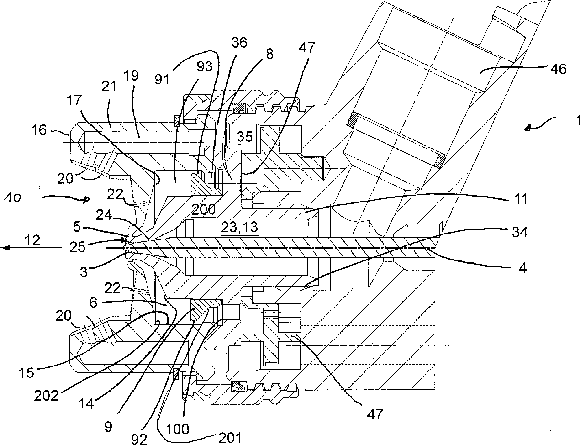
Düsenanordnung (1, 1a) für eine Spritzpistole, insbesondere für eine Farbspritzpistole (2), mit einer zentralen Austrittsöffnung (3) für das zu verspritzenden Material, welche von einem Ringspalt (5) umgeben ist, wobei der Ringspalt (5) innerhalb der Düsenanordnung (1) über einen Ringkanal (6) mit einer Vielzahl etwa achsenparalleler, um die zentrale Achse (4) der Düsenanordnung (1) liegender Bohrungen (8) in Verbindung steht und über diese Bohrungen (8) und den Ringkanal (6) mit Druckluft beaufschlagbar ist, und bei welcher innerhalb des Ringkanals (6) und gegenüber der Bohrungen (8) eine Luftumlenkscheibe (9) angeordnet ist, dadurch gekennzeichnet, dass die Düsenanordnung (1) im Bereich der Luftumlenkscheibe (9) mit wenigstens einem aerodynamisch wirksamen Element (91, 93, 94) ausgestattet ist.Nozzle arrangement (1, 1a) for a spray gun, in particular for a paint spray gun (2), with a central outlet opening (3) for the material to be sprayed, which is surrounded by an annular gap (5), wherein the annular gap (5) within the nozzle arrangement (1) via a ring channel (6) with a plurality of approximately axially parallel, about the central axis (4) of the nozzle assembly (1) lying holes (8) is in communication and via these holes (8) and the annular channel (6) with compressed air can be acted upon, and in which within the annular channel (6) and with respect to the bores (8) a Luftumlenkscheibe (9) is arranged, characterized in that the nozzle arrangement (1) in the region of Luftumlenkscheibe (9) with at least one aerodynamically active element ( 91, 93, 94) is equipped.
Description
Die Erfindung betrifft eine Düsenanordnung für eine Spritzpistole, insbesondere für eine Farbspritzpistole sowie eine Spritzpistole mit einer derartigen Düsenanordnung gemäß dem berbegriff des Anspruchs 1.The The invention relates to a nozzle arrangement for a Spray gun, in particular for a paint spray gun and a spray gun with such a nozzle arrangement according to the term of claim 1.
Eine
derartige Düsenanordnung ist beispielsweise aus dem
Die beschriebene Anordnung weist den Nachteil auf, dass durch die über den Umfang angeordneten Versorgungsbohrungen innerhalb der Düsenanordnung die Luft nicht gleichmässig in den Ringspalt einströmt, wodurch sich keine optimal gleichmässige Verteilung des Luft-Farb-Gemisches im Rundstrahl ergibt. Würde man entlang des Umfangs des Ringspaltes den Luftdruck messen, so ergäbe sich eine etwa sinusförmige Modulation, wobei Maxima in den Winkelbereichen des Ringspalts auftreten, in denen sich auch die Bohrungen in der Farbdüse befinden und Minima dazwischen. Desweiteren hat diese Anordnung den Nachteil, dass die Luft aus den Versorgungsbohrungen je nach der Winkelstellung der die Bohrungen aufweisenden Farbdüse relativ zum Gehäuse bzw. zur Luftkappe der Farbspritzpistole unmittelbar in die Steuerbohrungen für die Hornluft gelangt, wenn die Versorgungsbohrungen etwa kolinear mit diesen Steuerbohrungen verlaufen. Hierdurch herrscht vor den Steuerbohrungen ein zu hoher Luftdruck und eine zu hohe Luftgeschwindigkeit und die Hornluft wird dadurch in unerwünschter Weise zu stark beeinflusst, was wiederum die Strahlform unerwünscht ändert. Das Strahlergebnis hängt somit von der relativen Stellung der die Hörner und die Steuerbohrungen aufweisenden Luftkappe zu dem die Versorgungsbohrungen aufweisenden Farbdüse ab. Die Stellung des in das Gehäuse der Farbspritzpistole eingeschraubten Farbdüse ist jedoch durch deren Gewindeanschnitt bedingt und damit weitgehend zufällig, so dass ein Teil der produzierten Pistolen unerwünschte Farbauftragseigenschaften aufweist.The described arrangement has the disadvantage that through the over the circumference arranged supply holes within the nozzle assembly the air does not flow evenly into the annular gap, whereby no optimal uniform distribution of Air-color mixture in the round jet results. Would you go along the circumference of the annular gap measure the air pressure, so would give is an approximately sinusoidal modulation, with maxima in The angular ranges of the annular gap occur in which also the holes are in the paint nozzle and minima in between. Furthermore, this arrangement has the disadvantage that the air from the Supply holes depending on the angular position of the holes having color nozzle relative to the housing or to the air cap of the paint spray gun directly into the control bores for the horn air passes when the supply holes about co-linear with these control bores. This prevails in front of the control bores too high air pressure and too high Air speed and the horn air is thereby undesirably Too much influence, which in turn changes the beam shape undesirable. The beam result thus depends on the relative position the air cap having the horns and the control bores to the paint holes having the supply holes. The position of the screwed into the housing of the paint spray gun However, ink nozzle is due to the threaded portion and thus largely coincidentally, so that part of the pistols produced having undesirable paint application properties.
Demgegenüber
verbesserte Eigenschaften weist eine Düsenanordnung für
Farbspritzpistolen gemäß dem europäischen
Patent
Aufgabe der Erfindung ist, eine Düsenanordnung der vorgenannten Art noch weiter zu verbessern.task the invention is a nozzle assembly of the aforementioned Art to further improve.
Diese Aufgabe wird durch eine Düsenanordnung gemäß Anspruch 1 gelöst. Weitere vorteilhafte Einzelheiten und Ausgestaltungen der Erfindung sind den Unteransprüchen und den Ausführungsbeispielen zu entnehmen, welche nachfolgend anhand von Zeichnungen beschrieben werden. Dabei zeigt:These The object is achieved by a nozzle arrangement according to claim 1 solved. Further advantageous details and embodiments The invention are the subclaims and the embodiments which is described below with reference to drawings become. Showing:
Die
in
Zur
genaueren Beschreibung der in
Die
in den
Im
Bereich der Austrittsöffnung
Das
Aussengewinde
Daran
schliesst sich ein Mittelteil
Von
dieser Vertiefung oder der Planfläche
Die
Funktion zur Luftverteilung und zur Abdichtung gegenüber
dem Gehäuse
Die
die Farbdüse
Die
Von
der Rückseite der Luftkappe
Die
zusammengebaute Anordnung aus Farbdüse
Die
Planringfläche
Erfindungswesentlich
ist, dass die Düsenanordnung
Im
vorliegenden Ausführungsbeispiel ist hierfür an
Unterseite des zylindrischen Bereichs
An
ihrem Übergangsbereich in den zylindrischen Bereich
Wesentlich
ist, dass der bisher gebräuchliche, bewährte Durchmesser
des zylindrischen Bereichs
In
einer anderen Variante könnte eine solche Luftleitfläche
Außerdem
ist die erfindungsgemäße Düsenanordnung
Die
erfindungsgemässe Düsenanordnung funktioniert
bei ihrem Einsatz an einer Farbspritzpistole wie folgt:
Beim
Betätigen des Betätigungshebels
When operating the operating lever
Weil
die Luftumlenkscheibe
Gleichzeitig
führt diese Strömungsführung zu einer
Beschleunigung der Strömung im Ringkanal
Die
Druckluft strömt nach der vorbeschriebenen Passage durch
den engen Bereich des Ringkanals
Durch
den sich in Richtung des Ringspaltes
Der
so gebildete Rundstrahl wird in ebenfalls an sich bekannter Weise
durch die Hornluft aus den Austrittslöchern
Bei
der in
Im
Bereich der Austrittsöffnung
Jedenfalls wird die Energie der Druckluft damit effizienter ausgenutzt. Auch könnte damit die Schallemission des Strahls zur Erhöhung des Arbeitsschutzes reduziert werden.In any case the energy of the compressed air is used more efficiently. Also could thus increase the noise emission of the beam of occupational safety.
Im Übrigen
ist der Düsenkopf
Bei
der in
Die
Nuten
Die beschriebenen Düsenanordnungen sind sowohl bei Hochdruck- als auch bei Niederdruckfarbspritzpistolen einsetzbar, weisen jedoch bei den modernen Niederdruckpistolen besondere Vorteile auf, da diese empfindlicher auf Druckschwankungen reagieren.The described nozzle arrangements are both at high pressure as well as in low-pressure paint spray guns, but have in the modern low-pressure guns special advantages because these are more sensitive to pressure fluctuations.
ZITATE ENTHALTEN IN DER BESCHREIBUNGQUOTES INCLUDE IN THE DESCRIPTION
Diese Liste der vom Anmelder aufgeführten Dokumente wurde automatisiert erzeugt und ist ausschließlich zur besseren Information des Lesers aufgenommen. Die Liste ist nicht Bestandteil der deutschen Patent- bzw. Gebrauchsmusteranmeldung. Das DPMA übernimmt keinerlei Haftung für etwaige Fehler oder Auslassungen.This list The documents listed by the applicant have been automated generated and is solely for better information recorded by the reader. The list is not part of the German Patent or utility model application. The DPMA takes over no liability for any errors or omissions.
Zitierte PatentliteraturCited patent literature
- - DE 9001265 U [0002] - DE 9001265 U [0002]
- - EP 710506 B1 [0004] - EP 710506 B1 [0004]
Claims (36)
Priority Applications (1)
| Application Number | Priority Date | Filing Date | Title |
|---|---|---|---|
| DE202010012449U DE202010012449U1 (en) | 2010-09-10 | 2010-09-10 | Nozzle arrangement for a spray gun, in particular for a paint spray gun |
Applications Claiming Priority (1)
| Application Number | Priority Date | Filing Date | Title |
|---|---|---|---|
| DE202010012449U DE202010012449U1 (en) | 2010-09-10 | 2010-09-10 | Nozzle arrangement for a spray gun, in particular for a paint spray gun |
Publications (1)
| Publication Number | Publication Date |
|---|---|
| DE202010012449U1 true DE202010012449U1 (en) | 2010-12-02 |
Family
ID=43299543
Family Applications (1)
| Application Number | Title | Priority Date | Filing Date |
|---|---|---|---|
| DE202010012449U Expired - Lifetime DE202010012449U1 (en) | 2010-09-10 | 2010-09-10 | Nozzle arrangement for a spray gun, in particular for a paint spray gun |
Country Status (1)
| Country | Link |
|---|---|
| DE (1) | DE202010012449U1 (en) |
Cited By (19)
| Publication number | Priority date | Publication date | Assignee | Title |
|---|---|---|---|---|
| DE202011102622U1 (en) * | 2011-06-30 | 2012-10-01 | Sata Gmbh & Co. Kg | Easy to clean spray gun and accessories for this |
| EP2878380A1 (en) * | 2013-12-02 | 2015-06-03 | Hsien-Chao Shih | Paint spray gun comprising an even-pressure diverting housing structure |
| CN104722422A (en) * | 2013-12-18 | 2015-06-24 | 萨塔有限两合公司 | Air Nozzle Closure for a Spray Gun |
| US9327301B2 (en) | 2008-03-12 | 2016-05-03 | Jeffrey D. Fox | Disposable spray gun cartridge |
| US9333519B2 (en) | 2010-12-02 | 2016-05-10 | Sata Gmbh & Co. Kg | Spray gun and accessories |
| USD768820S1 (en) | 2014-09-03 | 2016-10-11 | Sata Gmbh & Co. Kg | Paint spray gun with pattern |
| USD770593S1 (en) | 2014-07-31 | 2016-11-01 | Sata Gmbh & Co. Kg | Paint spray gun |
| US9533317B2 (en) | 2009-07-08 | 2017-01-03 | Sata Gmbh & Co. Kg | Paint spray gun |
| DE102015016474A1 (en) * | 2015-12-21 | 2017-06-22 | Sata Gmbh & Co. Kg | Air cap and nozzle assembly for a spray gun and spray gun |
| US9782784B2 (en) | 2010-05-28 | 2017-10-10 | Sata Gmbh & Co. Kg | Nozzle head for a spray device |
| US9878336B2 (en) | 2006-12-05 | 2018-01-30 | Sata Gmbh & Co. Kg | Fluid reservoir for a paint spray gun |
| US10189037B2 (en) | 2011-06-30 | 2019-01-29 | Sata Gmbh & Co. Kg | Easy-to-clean spray gun, accessories therefor, and mounting and dismounting methods |
| US10471449B2 (en) | 2016-08-19 | 2019-11-12 | Sata Gmbh & Co. Kg | Air cap arrangement and spray gun |
| DE102018118738A1 (en) * | 2018-08-01 | 2020-02-06 | Sata Gmbh & Co. Kg | Base body for a spray gun, spray guns, spray gun set, method for producing a base body for a spray gun and method for converting a spray gun |
| DE102018118737A1 (en) * | 2018-08-01 | 2020-02-06 | Sata Gmbh & Co. Kg | Nozzle for a spray gun, nozzle set for a spray gun, spray guns and method for producing a nozzle for a spray gun |
| US10702879B2 (en) | 2014-07-31 | 2020-07-07 | Sata Gmbh & Co. Kg | Spray gun manufacturing method, spray gun, spray gun body and cover |
| US10835911B2 (en) | 2016-08-19 | 2020-11-17 | Sata Gmbh & Co. Kg | Trigger for a spray gun and spray gun having same |
| US11141747B2 (en) | 2015-05-22 | 2021-10-12 | Sata Gmbh & Co. Kg | Nozzle arrangement for a spray gun |
| US11826771B2 (en) | 2018-08-01 | 2023-11-28 | Sata Gmbh & Co. Kg | Set of nozzles for a spray gun, spray gun system, method for embodying a nozzle module, method for selecting a nozzle module from a set of nozzles for a paint job, selection system and computer program product |
Citations (2)
| Publication number | Priority date | Publication date | Assignee | Title |
|---|---|---|---|---|
| DE9001265U1 (en) | 1990-02-05 | 1990-04-12 | Sata - Farbspritztechnik Gmbh & Co, 7140 Ludwigsburg, De | |
| EP0710506B1 (en) | 1994-10-05 | 1997-06-04 | SATA-FARBSPRITZTECHNIK GmbH & Co. | Nozzle for paint spray gun |
-
2010
- 2010-09-10 DE DE202010012449U patent/DE202010012449U1/en not_active Expired - Lifetime
Patent Citations (2)
| Publication number | Priority date | Publication date | Assignee | Title |
|---|---|---|---|---|
| DE9001265U1 (en) | 1990-02-05 | 1990-04-12 | Sata - Farbspritztechnik Gmbh & Co, 7140 Ludwigsburg, De | |
| EP0710506B1 (en) | 1994-10-05 | 1997-06-04 | SATA-FARBSPRITZTECHNIK GmbH & Co. | Nozzle for paint spray gun |
Cited By (29)
| Publication number | Priority date | Publication date | Assignee | Title |
|---|---|---|---|---|
| US9878336B2 (en) | 2006-12-05 | 2018-01-30 | Sata Gmbh & Co. Kg | Fluid reservoir for a paint spray gun |
| US9327301B2 (en) | 2008-03-12 | 2016-05-03 | Jeffrey D. Fox | Disposable spray gun cartridge |
| US9533317B2 (en) | 2009-07-08 | 2017-01-03 | Sata Gmbh & Co. Kg | Paint spray gun |
| US9782784B2 (en) | 2010-05-28 | 2017-10-10 | Sata Gmbh & Co. Kg | Nozzle head for a spray device |
| US9333519B2 (en) | 2010-12-02 | 2016-05-10 | Sata Gmbh & Co. Kg | Spray gun and accessories |
| US9782785B2 (en) | 2010-12-02 | 2017-10-10 | Sata Gmbh & Co. Kg | Spray gun and accessories |
| DE202011102622U1 (en) * | 2011-06-30 | 2012-10-01 | Sata Gmbh & Co. Kg | Easy to clean spray gun and accessories for this |
| US10189037B2 (en) | 2011-06-30 | 2019-01-29 | Sata Gmbh & Co. Kg | Easy-to-clean spray gun, accessories therefor, and mounting and dismounting methods |
| EP2878380A1 (en) * | 2013-12-02 | 2015-06-03 | Hsien-Chao Shih | Paint spray gun comprising an even-pressure diverting housing structure |
| EP2886199A1 (en) * | 2013-12-18 | 2015-06-24 | SATA GmbH & Co. KG | Mounting of the air cap of a paint spray gun |
| US9409197B2 (en) | 2013-12-18 | 2016-08-09 | Sata Gmbh & Co. Kg | Air nozzle closure for a spray gun |
| CN104722422A (en) * | 2013-12-18 | 2015-06-24 | 萨塔有限两合公司 | Air Nozzle Closure for a Spray Gun |
| USD770593S1 (en) | 2014-07-31 | 2016-11-01 | Sata Gmbh & Co. Kg | Paint spray gun |
| US10702879B2 (en) | 2014-07-31 | 2020-07-07 | Sata Gmbh & Co. Kg | Spray gun manufacturing method, spray gun, spray gun body and cover |
| USD798419S1 (en) | 2014-07-31 | 2017-09-26 | Sata Gmbh & Co. Kg | Paint spray gun |
| USD835235S1 (en) | 2014-07-31 | 2018-12-04 | Sata Gmbh & Co. Kg | Paint spray gun |
| USD768820S1 (en) | 2014-09-03 | 2016-10-11 | Sata Gmbh & Co. Kg | Paint spray gun with pattern |
| US11141747B2 (en) | 2015-05-22 | 2021-10-12 | Sata Gmbh & Co. Kg | Nozzle arrangement for a spray gun |
| US10464076B2 (en) | 2015-12-21 | 2019-11-05 | Sata Gmbh & Co. Kg | Air cap and nozzle assembly for a spray gun, and spray gun |
| DE102015016474A1 (en) * | 2015-12-21 | 2017-06-22 | Sata Gmbh & Co. Kg | Air cap and nozzle assembly for a spray gun and spray gun |
| US10471449B2 (en) | 2016-08-19 | 2019-11-12 | Sata Gmbh & Co. Kg | Air cap arrangement and spray gun |
| US10835911B2 (en) | 2016-08-19 | 2020-11-17 | Sata Gmbh & Co. Kg | Trigger for a spray gun and spray gun having same |
| DE102018118738A1 (en) * | 2018-08-01 | 2020-02-06 | Sata Gmbh & Co. Kg | Base body for a spray gun, spray guns, spray gun set, method for producing a base body for a spray gun and method for converting a spray gun |
| DE102018118737A1 (en) * | 2018-08-01 | 2020-02-06 | Sata Gmbh & Co. Kg | Nozzle for a spray gun, nozzle set for a spray gun, spray guns and method for producing a nozzle for a spray gun |
| EP3610950A1 (en) | 2018-08-01 | 2020-02-19 | SATA GmbH & Co. KG | Nozzle for a spray gun, nozzle set for a spray gun, spray guns and method for producing a nozzle for a spray gun |
| EP3626352A1 (en) | 2018-08-01 | 2020-03-25 | SATA GmbH & Co. KG | Base body for a spray gun, spray guns, spray gun set and method for converting a spray gun |
| US11801521B2 (en) | 2018-08-01 | 2023-10-31 | Sata Gmbh & Co. Kg | Main body for a spray gun, spray guns, spray gun set, method for producing a main body for a spray gun and method for converting a spray gun |
| US11826771B2 (en) | 2018-08-01 | 2023-11-28 | Sata Gmbh & Co. Kg | Set of nozzles for a spray gun, spray gun system, method for embodying a nozzle module, method for selecting a nozzle module from a set of nozzles for a paint job, selection system and computer program product |
| US11865558B2 (en) | 2018-08-01 | 2024-01-09 | Sata Gmbh & Co. Kg | Nozzle for a spray gun, nozzle set for a spray gun, spray guns and methods for producing a nozzle for a spray gun |
Similar Documents
| Publication | Publication Date | Title |
|---|---|---|
| DE202010012449U1 (en) | Nozzle arrangement for a spray gun, in particular for a paint spray gun | |
| EP0710506B1 (en) | Nozzle for paint spray gun | |
| EP2576079B1 (en) | Nozzle head for a spray gun | |
| DE10304386B4 (en) | Double fluid swirl nozzle with self-cleaning spigot | |
| EP2017010B1 (en) | Atomiser for a spray gun | |
| DE102015006484A1 (en) | Nozzle arrangement for a spray gun, in particular paint spray gun and spray gun, in particular paint spray gun | |
| DE2422597B2 (en) | Spray device for the hydrostatic atomization of paint and other liquids | |
| DE112006002295T5 (en) | Spray nozzle arrangement for atomization by means of external air mixture | |
| EP0408786A1 (en) | Nozzle head | |
| DE2549974A1 (en) | DEVICE FOR DUSTING FLOWABLE MEDIA, SUCH AS COLORS, VARNISHES, ETC. | |
| DE1577919B2 (en) | ELECTROSTATICALLY WORKING PAINT SPRAY DEVICE WITH ADJUSTABLE OPENING ANGLE OF THE PAINT CONE | |
| DE102018118737A1 (en) | Nozzle for a spray gun, nozzle set for a spray gun, spray guns and method for producing a nozzle for a spray gun | |
| EP3626352A1 (en) | Base body for a spray gun, spray guns, spray gun set and method for converting a spray gun | |
| DE102012014965A1 (en) | nozzle assembly | |
| DE102019103248A1 (en) | Laser processing head with the function of rectifying auxiliary gas | |
| CH663731A5 (en) | SPRAYER FOR COATING WITH POWDER. | |
| DE102012104771A1 (en) | spray gun | |
| DE2502493A1 (en) | YARN TEXTURING NOZZLE | |
| CH641062A5 (en) | SPRAYER HEAD ON A PAINT SPRAY GUN. | |
| EP1470864B1 (en) | Two-fluid spray nozzle | |
| EP3554416B1 (en) | Mixing chamber and handpiece | |
| EP1280610B1 (en) | External mixing nozzle | |
| DE2757522C2 (en) | Round or ring jet nozzle for generating and blasting a mist or aerosol for coating objects | |
| EP1201316B1 (en) | High-speed rotary atomizer for powder paint | |
| DE2356229B2 (en) | Truncated cone-shaped atomizer nozzle having radial gas channels |
Legal Events
| Date | Code | Title | Description |
|---|---|---|---|
| R207 | Utility model specification |
Effective date: 20110105 |
|
| R150 | Utility model maintained after payment of first maintenance fee after three years | ||
| R150 | Utility model maintained after payment of first maintenance fee after three years |
Effective date: 20131008 |
|
| R151 | Utility model maintained after payment of second maintenance fee after six years | ||
| R152 | Utility model maintained after payment of third maintenance fee after eight years |