EP0005035B1 - A method of preparing a tubular product by electrostatic spinning - Google Patents
A method of preparing a tubular product by electrostatic spinning Download PDFInfo
- Publication number
- EP0005035B1 EP0005035B1 EP79300612A EP79300612A EP0005035B1 EP 0005035 B1 EP0005035 B1 EP 0005035B1 EP 79300612 A EP79300612 A EP 79300612A EP 79300612 A EP79300612 A EP 79300612A EP 0005035 B1 EP0005035 B1 EP 0005035B1
- Authority
- EP
- European Patent Office
- Prior art keywords
- sheath
- lumen
- fibres
- former
- core
- Prior art date
- Legal status (The legal status is an assumption and is not a legal conclusion. Google has not performed a legal analysis and makes no representation as to the accuracy of the status listed.)
- Expired
Links
Images
Classifications
-
- D—TEXTILES; PAPER
- D01—NATURAL OR MAN-MADE THREADS OR FIBRES; SPINNING
- D01D—MECHANICAL METHODS OR APPARATUS IN THE MANUFACTURE OF ARTIFICIAL FILAMENTS, THREADS, FIBRES, BRISTLES OR RIBBONS
- D01D5/00—Formation of filaments, threads, or the like
- D01D5/0007—Electro-spinning
- D01D5/0061—Electro-spinning characterised by the electro-spinning apparatus
- D01D5/0076—Electro-spinning characterised by the electro-spinning apparatus characterised by the collecting device, e.g. drum, wheel, endless belt, plate or grid
-
- A—HUMAN NECESSITIES
- A61—MEDICAL OR VETERINARY SCIENCE; HYGIENE
- A61F—FILTERS IMPLANTABLE INTO BLOOD VESSELS; PROSTHESES; DEVICES PROVIDING PATENCY TO, OR PREVENTING COLLAPSING OF, TUBULAR STRUCTURES OF THE BODY, e.g. STENTS; ORTHOPAEDIC, NURSING OR CONTRACEPTIVE DEVICES; FOMENTATION; TREATMENT OR PROTECTION OF EYES OR EARS; BANDAGES, DRESSINGS OR ABSORBENT PADS; FIRST-AID KITS
- A61F2/00—Filters implantable into blood vessels; Prostheses, i.e. artificial substitutes or replacements for parts of the body; Appliances for connecting them with the body; Devices providing patency to, or preventing collapsing of, tubular structures of the body, e.g. stents
- A61F2/02—Prostheses implantable into the body
- A61F2/04—Hollow or tubular parts of organs, e.g. bladders, tracheae, bronchi or bile ducts
- A61F2/06—Blood vessels
-
- A—HUMAN NECESSITIES
- A61—MEDICAL OR VETERINARY SCIENCE; HYGIENE
- A61L—METHODS OR APPARATUS FOR STERILISING MATERIALS OR OBJECTS IN GENERAL; DISINFECTION, STERILISATION OR DEODORISATION OF AIR; CHEMICAL ASPECTS OF BANDAGES, DRESSINGS, ABSORBENT PADS OR SURGICAL ARTICLES; MATERIALS FOR BANDAGES, DRESSINGS, ABSORBENT PADS OR SURGICAL ARTICLES
- A61L27/00—Materials for grafts or prostheses or for coating grafts or prostheses
- A61L27/14—Macromolecular materials
-
- D—TEXTILES; PAPER
- D04—BRAIDING; LACE-MAKING; KNITTING; TRIMMINGS; NON-WOVEN FABRICS
- D04H—MAKING TEXTILE FABRICS, e.g. FROM FIBRES OR FILAMENTARY MATERIAL; FABRICS MADE BY SUCH PROCESSES OR APPARATUS, e.g. FELTS, NON-WOVEN FABRICS; COTTON-WOOL; WADDING ; NON-WOVEN FABRICS FROM STAPLE FIBRES, FILAMENTS OR YARNS, BONDED WITH AT LEAST ONE WEB-LIKE MATERIAL DURING THEIR CONSOLIDATION
- D04H1/00—Non-woven fabrics formed wholly or mainly of staple fibres or like relatively short fibres
- D04H1/70—Non-woven fabrics formed wholly or mainly of staple fibres or like relatively short fibres characterised by the method of forming fleeces or layers, e.g. reorientation of fibres
- D04H1/72—Non-woven fabrics formed wholly or mainly of staple fibres or like relatively short fibres characterised by the method of forming fleeces or layers, e.g. reorientation of fibres the fibres being randomly arranged
- D04H1/728—Non-woven fabrics formed wholly or mainly of staple fibres or like relatively short fibres characterised by the method of forming fleeces or layers, e.g. reorientation of fibres the fibres being randomly arranged by electro-spinning
-
- Y—GENERAL TAGGING OF NEW TECHNOLOGICAL DEVELOPMENTS; GENERAL TAGGING OF CROSS-SECTIONAL TECHNOLOGIES SPANNING OVER SEVERAL SECTIONS OF THE IPC; TECHNICAL SUBJECTS COVERED BY FORMER USPC CROSS-REFERENCE ART COLLECTIONS [XRACs] AND DIGESTS
- Y10—TECHNICAL SUBJECTS COVERED BY FORMER USPC
- Y10S—TECHNICAL SUBJECTS COVERED BY FORMER USPC CROSS-REFERENCE ART COLLECTIONS [XRACs] AND DIGESTS
- Y10S623/00—Prosthesis, i.e. artificial body members, parts thereof, or aids and accessories therefor
- Y10S623/901—Method of manufacturing prosthetic device
Definitions
- This invention relates to tubular products and to processes for the production thereof.
- French Patent No. 2340079 and German DE A 2704771 describes the preparation of tubular products, for example, vascular prostheses, by a process involving the electrostatic spinning of liquids, e.g. solutions of fibre-forming materials, to give fibres which are then collected upon a shaped former, which may be a rod or tube of configuration corresponding to that which it is desired to impart to the internal surface of the product.
- the fibres obtained by this process are thin, usually of the order of 0.1 to 25 ⁇ m, preferably 0.5 to 10 pm and more preferably 1.0 to 5 ⁇ m and particularly preferably 1 pm ⁇ 20%.
- the process of electrostatic spinning involves the introduction of a liquid into an electric field whereby the liquid is caused to produce fibres. After being drawn from the liquid the fibres harden, which may involve mere cooling (where the liquid or a component thereof is normally solid at room temperature, for example), chemical hardening or evaporation of solvent, and the hardening or hardened fibres may be collected upon a suitably charged surface.
- tubular firbrous products using the technique of electrostatic spinning, and particularly electrostatic spinning of fibre-forming polymer containing liquid compositions comprising a polyurethane, so that tubular products comprising polyurethane fibres are obtained.
- a vascular prosthesis particularly a synthetic blood vessel.
- Other applications for such tubular products include use as ducts of a variety of kinds, e.g. urinary, air or bile as well as 'conduit' through which for example a wire or other device or structure may pass or lie.
- the lumen of the tube is small (particularly less than, e.g. 1 cm, and especially less than 5 mm I.D.), or where the tube is long, or thinwalled or fragile, and we have therefore found it advantageous to spin the tube onto a former consisting of a core and a sheath of suitable material and configuration.
- the present invention provides a method of preparing a tubular product by electrostatically spinning a fibre-forming material and collecting the resulting spun fibres upon a former in which the former comprises a core and removable sheath thereon, the sheath being non-electrically-insulating so that spun fibres are attracted to the sheath and collect upon its surface.
- 'former' we mean a structure upon which the electrostatically spun fibres are collected and which imparts to the resulting product, comprising the mass of collected fibres, a desired configuration.
- the core which serves to maintain the desired configuration of the sheath and if necessary to impart motion to it is conveniently a mandrel of substantially cylindrical configuration and of diameter approximating to the desired internal diameter of the spun tubular product.
- the core preferably is electrically conducting and more preferably is a metal, although electrical conduction may not be essential if the sheath is appropriately conducting in which case the core may be of any suitable material including plastics material.
- the core which may be hollow or solid, preferably has a smooth surface to facilitate sliding of the sheath upon the core when it is to be removed therefrom, although to prevent undesirable slip between the core and sheath, when, for example, the sheath is to be rotated during collection of the fibres, it may be desirable to encourage a degree of friction between the core and the sheath, for example by roughening the surface of the core, particularly so as to reduce slip in a rotational direction around the long axis of the core, not in a longitudinal direction. This may be accomplished for example, by lightly grooving the surface of the core in a direction parallel to its long axis.
- the core will conveniently be mounted so that it may be rotated around its long axis and provided with electrical contacts so that its electrical charge (which may be at earth potential) may be adjusted as required.
- the sheath comprises a suitable non-electrically-insulating material, most conveniently a metal so that when the former (core, sheath or both as appropriate) is charged in relation to the fibres, the fibres of the electrostatically spun material will be attracted to it and collect upon its surface.
- the sheath will be made of sheet metal, or metal foil, although the use of a sheath made of fibrous material, e.g. polymer, some or all of the fibres preferably being electrically conducting, or polymeric or other sheet or tube material is not excluded.
- the sheath will be made of metal foil of such a thickness that it can easily be deformed, and preferably collapsed so that it is capable of being withdrawn conveniently from the lumen of a tube spun upon it.
- the sheath comprises localised thickening or contouring as may be required for example to impart a desired contour or a particular configuration to the product of the process.
- the sheath may be desirable for the sheath to have one or more rigid extremities which may facilitate its handling and which can be detached, e.g. by cutting, removing the sheath from the tubular product.
- a suitable slip enhancing material e.g. fluorinated hydrocarbon to facilitate its removal from the core and/or tubular product, although this coating must not be such that the efficiency of the process of the invention is not unduly impaired for example by an insulating effect.
- the major part of the sheath should preferably be deformable and more preferably collapsible.
- it will comprise a metal foil, conveniently of thickness between 0.005 mm and 1 mm, preferably between 0.01 mm and 0.5 mm and more preferably between 0.01 mm and 0.025 mm.
- Most metals are suitable provided of course, that they do not react undesirably with any material with which they contact in the course of the process of the invention, that they are appropriately stable under the conditions of the process, and that they do not tend easily to contaminate the product undesirably, e.g. with toxic metal residues.
- Aluminium foil and tin foil are preferred metals.
- Removal of the sheath from within the tubular product is preferably preceded by collapse of the sheath, for example by crushing it gently although it may be removed by dissolution in a suitable solvent for the sheath (which solvent must obviously not undesirably affect the product).
- sheath will be wrapped around the core so that after removal of the sheath and tubular product from the core an edge of the sheath may be gripped and the sheath wound to release it from the product.
- Materials suitable for the preparation of tubular products according to the invention include polymeric substances and in particular biologically acceptable polymeric substances.
- biologically acceptable we mean substances that do not decompose or otherwise react undesirably when in contact with biological tissue with which they are likely to come into contact in use, for at least a useful period of time.
- fluorinated hydrocarbons e.g. PTFE which conveniently may be spun from a dispersion of the material in a suitable dispersing agent
- polyurethanes which may be spun from solution, although other biologically acceptable polymers which can be electrostatically spun to give fibres are not excluded.
- the tubular products prepared according to the present invention may be spun from a solution of or a dispersion of a polymer or precursors thereof when these can later be converted into the polymer.
- Polymers which may be conveniently spun from solution include high molecular weight fibre forming thermoplastics; in particular we would mention polyurethanes, polyamides and polyacrylonitrile.
- Polymers which may conveniently be spun from dispersion include polytetrafluoroethylene and polyesters as well as those listed above.
- urea formaldehyde which may be cross-linked subsequent to spinning by treatment with acid vapour.
- Water soluble polymers e.g. polyvinyl alcohol, polyvinyl pyrrolidone, and polyethylene oxide
- aqueous solution e.g. water soluble polymers, e.g. polyvinyl alcohol, polyvinyl pyrrolidone, and polyethylene oxide
- tubes prepared from such materials may be used as prepared, preferably such tubes are given at least a degree of insolubility in aqueous medium e.g. by cross-linking the polymer with a suitable reagent after spinning.
- the spinning material comprises preferably also a solution of an additional component which acts to enhance the viscosity of the suspension and to improve its fibre forming properties.
- an additional component which acts to enhance the viscosity of the suspension and to improve its fibre forming properties.
- an additional organic polymeric material Most convenient for this purpose, we have found, is an additional organic polymeric material.
- the preferred spinning material is a solution or suspension which preferably comprises an organic polymer in an amount such that it is capable of forming a fibre and has cohesion properties such that the fibre form is retained during any post fibreization hardening until the fibre has hardened sufficiently not to lose its fibrous shape on detachment from a support where this is appropriate.
- tubes are spun from solution they comprise point bonded fibres and are often strong enough for use without any further treatment.
- tubes are spun from dispersion they often have a tendency to be friable, being mere agglomerations of discrete particles held together in the form of fibres by the additional organic polymeric component present.
- such tubes are sintered so that the particles soften and flow into each other and the fibres may become point bonded.
- PTFE sintering may conveniently be carried out between 330°C and 450°C preferably between 370°C and 390°C. Sterilisation may proceed concurrently during the sintering process.
- the sintering temperature in the case of PTFE is usually sufficiently high to destroy completely any undesirable organic component in the final product, e.g. material added solely to enhance viscosity or emulsifying agent.
- the additional organic component need be employed only in a relatively small proportion (usually within the range 0.001 to 12% and preferably 0.01 to 3%) by weight of the suspension, although the precise concentration for any particular application can easily be determined by trial.
- the degree of polymerisation of the additional organic component where it is employed is preferably greater than about 2000 units linearly; a wide range of such polymers is available.
- An important requirement is solubility of the polymer in the selected solvent or suspending medium which is preferably water.
- water-soluble polymeric compounds we may mention polyethylene oxide, polyacrylamide, polyvinyl pyrrolidone and polyvinyl alcohol; where an organic medium is employed to prepare the spinning material, either as the sole liquid solvent or as a component thereof, a further wide range of organic polymeric compounds is available, for example, polystyrene and polymethylmethacrylate.
- the degree of polymerisation of the polymer will be selected in the light of required solubility and the ability of the polymer to impart the desired properties of cohesion and viscosity to the fibreizable liquid.
- the viscosity of the fibreizable liquid whether due solely to the presence of the fibreizable polymer or partly contributed to by the additional organic polymer should be greater than 0.1 but not greater than 150 poise. Preferably it is between 0.5 to 50 poise and more preferably between 1 and 10 poise, (viscosities being measured at low shear rates and at the spinning temperature).
- the viscosity required using a given additional organic polymer will vary with the molecular weight of the polymer, i.e. the lower the molecular weight the higher the final viscosity needed. Again, as the molecular weight of the polymer is increased a lower concentration of it is required to give good fibreization.
- the concentration of the fibreizable polymer will depend upon the amount required to provide adequate fibre properties, and will be influenced also by the need to produce a liquid of appropriate viscosity and speed of fibre hardening.
- a concentration within the range 25% w/w to saturation in the case of dispersion, 'saturation' means the maximum concentration which may be included without destroying the useful spinnability of the liquid
- the spinning material should have some electrical conductivity, although this may vary between quite wide limits; for example we prefer to employ solutions having conductivity within the range 1 x 10- 8 to 5 x 10- 2 siemens cm -1 ,
- any convenient method may be employed to bring the spinning material into the electrostatic field, for example we have supplied the spinning liquid to an appropriate position in the electrostatic field by feeding it to a nozzle from which it is drawn by the field, whereupon fibreization occurs.
- Any suitable apparatus can be employed for this purpose, thus we have fed the spinning material from a syringe reservoir to the tip of an earthed syringe needle, the tip being located at an appropriate distance from the electrostatically charged surface of a former. Upon leaving the needle the material forms fibre between the needle tip and the former.
- Droplets of the spinning liquid may be introduced into the field in other ways, which will be apparent to the skilled man, the only requirement being that they can be held within the field at a distance from the electrostatically charged surface such that fibreization occurs.
- a continuous carrier e.g. a metal wire.
- nozzles may be used to increase the rate of fibre production.
- Alternative means of bringing the fibreizable liquid into the charge field may be employed, for example a slot or a perforated plate (the perforations being fed with fibreizable liquid from a manifold) may be employed.
- the electrostatic potential employed will usually be within the range 5 Kv to 1000 Kv, conveniently 10-100 Kv and preferably 10-50 Kv over a distance of 7-15 cm. Any appropriate method of producing the desired potential may be employed.
- Tubes prepared according to the present invention may have walls between a few microns and a few centimetres thick, the choice of thickness will depend on the particular application and will be selected in the light of experience of the strength of the product after spinning and the conditions to which it will be exposed.
- the thickness of wall for use as a vascular graft will usually be within the range 5-25% preferably 9-18% and more preferably 10-12% of the internal diameter of the lumen. Spinning will usually, therefore be continued until a wall of desired thickness has been deposited, taking into consideration any dimensional changes which may result from shrinkage e.g. on drying or cross-linking, or from elastic contraction of the fibres.
- the pore size of the tubes prepared according to the invention will usually be between 0.001 p and 500 p.
- the average surface pore dimension should be of the order of 5 to 25 ⁇ particularly preferably between 7 and 15 p, although pore size in the bulk of the material may average about 1 pm.
- Such synthetic vessels consist of tubes, preferably of circular cross-section, which may be of the constant diameter along their length or may be of varying diameter or configuration, for example they may taper or they may include constrictions or grooves to facilitate their location.
- Such tubes may be of dimensions and configuration appropriate to the intended function and location in which they are to be employed, for example as a replacement for a diseased blood vessel, and they may, of course, be prepared upon a mandrel of corresponding dimensions and configurations.
- Such synthetic vessels may be of the order of 0.1 to 3 cm, preferably 0.2 to 2 cm, and more preferably 0.3 to 0.8 cm in internal diameter.
- the thickness of the wall of the vessel may vary between wide limits, and will depend inter alia upon the strength and elasticity required in the tube as well as the need for it to be convenient to locate and affix. Usually the thickness of the vessel wall will be within the range 0.1 to 2 mm, preferably between 0.1 to 1 mm.
- the synthetic vessel of the invention may be of any of a variety of configurations, for example it may be a straight or bent tube, a loop, an enastomosis or it may be bifurcate. Such forms may be obtained by spinning upon a former of suitable shape.
- the preferred vessels comprise fibres of an appropriate polyurethane selected from the wide range of materials available on the basis of ease of fabrication, lack of toxicity, solubility, mechanical properties, degree of biodegradability, etc. While it is preferred that a completely polymerised polyurethane dissolved in a suitable solvent (together with other additives as required) is used as the spinning solution we do not exclude the possibility of spinning incompletely polymerised polyurethane, completion of polymerisation being effected during or after spinning.
- the apparatus was as shown diagrammatically in figure 1.
- the former onto which the fibres were collected consisted of a metal mandrel or core (1) 20 mm in diameter and 25 cm long having a sheath of aluminium foil (2) 0.02 mm and 20 cm long wrapped around it.
- the former which was charged to 50 Kv, was rotated about its long axis at about 300 rpm.
- the fibre forming material (3) was fed into the electric field surrounding the former from a bank of 3 syringes (4), the needles of which were 3 cm long and 0.05 cm I.D. at the rate of 1 gm/hr/needle.
- the fibre forming material was a 15% solution polyether urethane block copolymer in DMF/Butanone (3:2 w/w) solution.
- the dried solid polymer had a hardness within the range 30-40° shore D.
- the droplet Upon introduction of the polymer into the electric field the droplet instantly disintegrated into fibres which were drawn to the mandrel, (over a distance of 10 cm against a counter current of air at 40°C moving at about 25 cm/sec and deposited upon it in a tubular layer (5).
- Example 1 The process of Example 1 was repeated, except that the outside of the aluminium foil sheath was coated with PTFE spray-on release agent which facilitated release of the fibrous tube, the I.D. of the product obtained was 4 mm the wall thickness was 0.5 mm, spinning being effected through a bank of 3 needles, each delivering 1 gm of solution/hour.
Description
- This invention relates to tubular products and to processes for the production thereof.
- French Patent No. 2340079 and German DE A 2704771 describes the preparation of tubular products, for example, vascular prostheses, by a process involving the electrostatic spinning of liquids, e.g. solutions of fibre-forming materials, to give fibres which are then collected upon a shaped former, which may be a rod or tube of configuration corresponding to that which it is desired to impart to the internal surface of the product. The fibres obtained by this process are thin, usually of the order of 0.1 to 25 µm, preferably 0.5 to 10 pm and more preferably 1.0 to 5 µm and particularly preferably 1 pm ±20%.
- The process of electrostatic spinning involves the introduction of a liquid into an electric field whereby the liquid is caused to produce fibres. After being drawn from the liquid the fibres harden, which may involve mere cooling (where the liquid or a component thereof is normally solid at room temperature, for example), chemical hardening or evaporation of solvent, and the hardening or hardened fibres may be collected upon a suitably charged surface.
- The above mentioned French patent describes inter alia the production of tubular firbrous products using the technique of electrostatic spinning, and particularly electrostatic spinning of fibre-forming polymer containing liquid compositions comprising a polyurethane, so that tubular products comprising polyurethane fibres are obtained. One example of such tubular product is a vascular prosthesis, particularly a synthetic blood vessel. Other applications for such tubular products include use as ducts of a variety of kinds, e.g. urinary, air or bile as well as 'conduit' through which for example a wire or other device or structure may pass or lie.
- Occasionally difficulty has been experienced in removing the spun tubular product from the former. This is particularly the case where the lumen of the tube is small (particularly less than, e.g. 1 cm, and especially less than 5 mm I.D.), or where the tube is long, or thinwalled or fragile, and we have therefore found it advantageous to spin the tube onto a former consisting of a core and a sheath of suitable material and configuration.
- Accordingly the present invention provides a method of preparing a tubular product by electrostatically spinning a fibre-forming material and collecting the resulting spun fibres upon a former in which the former comprises a core and removable sheath thereon, the sheath being non-electrically-insulating so that spun fibres are attracted to the sheath and collect upon its surface.
- By 'former' we mean a structure upon which the electrostatically spun fibres are collected and which imparts to the resulting product, comprising the mass of collected fibres, a desired configuration. The core which serves to maintain the desired configuration of the sheath and if necessary to impart motion to it is conveniently a mandrel of substantially cylindrical configuration and of diameter approximating to the desired internal diameter of the spun tubular product. The core preferably is electrically conducting and more preferably is a metal, although electrical conduction may not be essential if the sheath is appropriately conducting in which case the core may be of any suitable material including plastics material. The core, which may be hollow or solid, preferably has a smooth surface to facilitate sliding of the sheath upon the core when it is to be removed therefrom, although to prevent undesirable slip between the core and sheath, when, for example, the sheath is to be rotated during collection of the fibres, it may be desirable to encourage a degree of friction between the core and the sheath, for example by roughening the surface of the core, particularly so as to reduce slip in a rotational direction around the long axis of the core, not in a longitudinal direction. This may be accomplished for example, by lightly grooving the surface of the core in a direction parallel to its long axis. The core will conveniently be mounted so that it may be rotated around its long axis and provided with electrical contacts so that its electrical charge (which may be at earth potential) may be adjusted as required.
- The sheath comprises a suitable non-electrically-insulating material, most conveniently a metal so that when the former (core, sheath or both as appropriate) is charged in relation to the fibres, the fibres of the electrostatically spun material will be attracted to it and collect upon its surface. Preferably the sheath will be made of sheet metal, or metal foil, although the use of a sheath made of fibrous material, e.g. polymer, some or all of the fibres preferably being electrically conducting, or polymeric or other sheet or tube material is not excluded. Most preferably the sheath will be made of metal foil of such a thickness that it can easily be deformed, and preferably collapsed so that it is capable of being withdrawn conveniently from the lumen of a tube spun upon it. We do not exclude the possibility that the sheath comprises localised thickening or contouring as may be required for example to impart a desired contour or a particular configuration to the product of the process. For example it may be desirable for the sheath to have one or more rigid extremities which may facilitate its handling and which can be detached, e.g. by cutting, removing the sheath from the tubular product. It is sometimes advantageous to coat at least part of one or both surfaces of the sheath with a suitable slip enhancing material e.g. fluorinated hydrocarbon to facilitate its removal from the core and/or tubular product, although this coating must not be such that the efficiency of the process of the invention is not unduly impaired for example by an insulating effect.
- The major part of the sheath, then, should preferably be deformable and more preferably collapsible. Conveniently it will comprise a metal foil, conveniently of thickness between 0.005 mm and 1 mm, preferably between 0.01 mm and 0.5 mm and more preferably between 0.01 mm and 0.025 mm. Most metals are suitable provided of course, that they do not react undesirably with any material with which they contact in the course of the process of the invention, that they are appropriately stable under the conditions of the process, and that they do not tend easily to contaminate the product undesirably, e.g. with toxic metal residues. Aluminium foil and tin foil are preferred metals.
- Removal of the sheath from within the tubular product is preferably preceded by collapse of the sheath, for example by crushing it gently although it may be removed by dissolution in a suitable solvent for the sheath (which solvent must obviously not undesirably affect the product).
- Most conveniently the sheath will be wrapped around the core so that after removal of the sheath and tubular product from the core an edge of the sheath may be gripped and the sheath wound to release it from the product.
- Materials suitable for the preparation of tubular products according to the invention include polymeric substances and in particular biologically acceptable polymeric substances. By biologically acceptable we mean substances that do not decompose or otherwise react undesirably when in contact with biological tissue with which they are likely to come into contact in use, for at least a useful period of time. As preferred substances we would mention fluorinated hydrocarbons, e.g. PTFE which conveniently may be spun from a dispersion of the material in a suitable dispersing agent, and polyurethanes which may be spun from solution, although other biologically acceptable polymers which can be electrostatically spun to give fibres are not excluded.
- The tubular products prepared according to the present invention may be spun from a solution of or a dispersion of a polymer or precursors thereof when these can later be converted into the polymer. Polymers which may be conveniently spun from solution include high molecular weight fibre forming thermoplastics; in particular we would mention polyurethanes, polyamides and polyacrylonitrile. Polymers which may conveniently be spun from dispersion include polytetrafluoroethylene and polyesters as well as those listed above. As an example of a polymer precursor which may be spun from solution we mention urea formaldehyde which may be cross-linked subsequent to spinning by treatment with acid vapour.
- Water soluble polymers, e.g. polyvinyl alcohol, polyvinyl pyrrolidone, and polyethylene oxide, may be spun from aqueous solution. While we do riot exclude the possiblity that tubes prepared from such materials may be used as prepared, preferably such tubes are given at least a degree of insolubility in aqueous medium e.g. by cross-linking the polymer with a suitable reagent after spinning.
- Where the products of the invention are spun from a dispersion the spinning material comprises preferably also a solution of an additional component which acts to enhance the viscosity of the suspension and to improve its fibre forming properties. Most convenient for this purpose, we have found, is an additional organic polymeric material.
- The preferred spinning material, then, is a solution or suspension which preferably comprises an organic polymer in an amount such that it is capable of forming a fibre and has cohesion properties such that the fibre form is retained during any post fibreization hardening until the fibre has hardened sufficiently not to lose its fibrous shape on detachment from a support where this is appropriate.
- Where tubes are spun from solution they comprise point bonded fibres and are often strong enough for use without any further treatment.
- Where the tubes are spun from dispersion they often have a tendency to be friable, being mere agglomerations of discrete particles held together in the form of fibres by the additional organic polymeric component present. Preferably such tubes are sintered so that the particles soften and flow into each other and the fibres may become point bonded. In the case of PTFE sintering may conveniently be carried out between 330°C and 450°C preferably between 370°C and 390°C. Sterilisation may proceed concurrently during the sintering process. The sintering temperature in the case of PTFE is usually sufficiently high to destroy completely any undesirable organic component in the final product, e.g. material added solely to enhance viscosity or emulsifying agent.
- The additional organic component need be employed only in a relatively small proportion (usually within the range 0.001 to 12% and preferably 0.01 to 3%) by weight of the suspension, although the precise concentration for any particular application can easily be determined by trial.
- The degree of polymerisation of the additional organic component where it is employed is preferably greater than about 2000 units linearly; a wide range of such polymers is available. An important requirement is solubility of the polymer in the selected solvent or suspending medium which is preferably water. As examples of water-soluble polymeric compounds we may mention polyethylene oxide, polyacrylamide, polyvinyl pyrrolidone and polyvinyl alcohol; where an organic medium is employed to prepare the spinning material, either as the sole liquid solvent or as a component thereof, a further wide range of organic polymeric compounds is available, for example, polystyrene and polymethylmethacrylate.
- The degree of polymerisation of the polymer will be selected in the light of required solubility and the ability of the polymer to impart the desired properties of cohesion and viscosity to the fibreizable liquid.
- We have found that generally the viscosity of the fibreizable liquid whether due solely to the presence of the fibreizable polymer or partly contributed to by the additional organic polymer should be greater than 0.1 but not greater than 150 poise. Preferably it is between 0.5 to 50 poise and more preferably between 1 and 10 poise, (viscosities being measured at low shear rates and at the spinning temperature). The viscosity required using a given additional organic polymer will vary with the molecular weight of the polymer, i.e. the lower the molecular weight the higher the final viscosity needed. Again, as the molecular weight of the polymer is increased a lower concentration of it is required to give good fibreization. Thus, as examples we would mention that in the preparation of polytetrafluoroethylene tubes we have found that using a polyethylene oxide of MW 100,000 as the additional organic polymer a concentration of about 12% by weight relative to the PTFE content is needed to give satisfactory fibreization whereas with a MW of 300,000 a concentration of 1 to 6% may be adequate. Again, at a MW of 600,000 a concentration of 1 to 4% is satisfactory, while at a MW of 4 x 10⁶ a concentration as low as 0.296 may give good fibreization.
- The concentration of the fibreizable polymer will depend upon the amount required to provide adequate fibre properties, and will be influenced also by the need to produce a liquid of appropriate viscosity and speed of fibre hardening. Thus in the case of a dispersion we may use a concentration within the range 25% w/w to saturation (in the case of dispersion, 'saturation' means the maximum concentration which may be included without destroying the useful spinnability of the liquid) preferably 40 to 70% and more preferably 50 to 60%, and in the case of a solution we may use a concentration within the range 8 to 60% w/w, preferably 10 to 20% w/w.
- It will be appreciated that the concentration of the components must each be adjusted to take account of the presence and concentration of any other and their relative effects upon viscosity, etc.
- The spinning material should have some electrical conductivity, although this may vary between quite wide limits; for example we prefer to employ solutions having conductivity within the range 1 x 10⁻⁸ to 5 x 10⁻² siemens cm-1,
- Any convenient method may be employed to bring the spinning material into the electrostatic field, for example we have supplied the spinning liquid to an appropriate position in the electrostatic field by feeding it to a nozzle from which it is drawn by the field, whereupon fibreization occurs. Any suitable apparatus can be employed for this purpose, thus we have fed the spinning material from a syringe reservoir to the tip of an earthed syringe needle, the tip being located at an appropriate distance from the electrostatically charged surface of a former. Upon leaving the needle the material forms fibre between the needle tip and the former.
- Droplets of the spinning liquid may be introduced into the field in other ways, which will be apparent to the skilled man, the only requirement being that they can be held within the field at a distance from the electrostatically charged surface such that fibreization occurs. For example they could be carried into the field on say, a continuous carrier, e.g. a metal wire.
- It will be appreciated that where the liquid is fed into the field through a nozzle, several nozzles may be used to increase the rate of fibre production. Alternative means of bringing the fibreizable liquid into the charge field may be employed, for example a slot or a perforated plate (the perforations being fed with fibreizable liquid from a manifold) may be employed.
- The electrostatic potential employed will usually be within the
range 5 Kv to 1000 Kv, conveniently 10-100 Kv and preferably 10-50 Kv over a distance of 7-15 cm. Any appropriate method of producing the desired potential may be employed. - To allow high production rates, hardening of the fibres should occur rapidly and this is facilitated by the use of concentrated fibreizing liquids (so that the minimum liquid has to be removed), easily volatile solvents (for example the liquid may be wholly or partly of low boiling organic liquid) and relatively high temperatures in the vicinity of the fibre formation. The use of a gaseous, usually air, blast, particularly if the gas is warm, will often accelerate hardening of the fibre; conveniently such a blast is counter-current. Careful direction of the air blast may also be used to cause the fibres, after detachment, to lay in a desired position or direction. However, using conditions as described in the Example no particular precautions were needed to ensure rapid hardening of PTFE fibres. We found that during its formation and travel from the nozzle to the belt sufficient hardening (dehydration in the case described) occurred at ambient temperature without the need for auxiliary hardening treatment, but in the production of other fibres e.g. polyurethanes, elevated temperature and counter-current air flow may be advantageous.
- Tubes prepared according to the present invention may have walls between a few microns and a few centimetres thick, the choice of thickness will depend on the particular application and will be selected in the light of experience of the strength of the product after spinning and the conditions to which it will be exposed. However, we have found that when using polyurethane as the fibres the thickness of wall for use as a vascular graft will usually be within the range 5-25% preferably 9-18% and more preferably 10-12% of the internal diameter of the lumen. Spinning will usually, therefore be continued until a wall of desired thickness has been deposited, taking into consideration any dimensional changes which may result from shrinkage e.g. on drying or cross-linking, or from elastic contraction of the fibres.
- The pore size of the tubes prepared according to the invention will usually be between 0.001 p and 500 p. For the tube to be sufficiently porous to allow penetration of cells into the surface layers, preferably the average surface pore dimension should be of the order of 5 to 25 µ particularly preferably between 7 and 15 p, although pore size in the bulk of the material may average about 1 pm.
- The invention is particularly useful in providing novel synthetic blood vessels or components thereof. Conveniently such synthetic vessels consist of tubes, preferably of circular cross-section, which may be of the constant diameter along their length or may be of varying diameter or configuration, for example they may taper or they may include constrictions or grooves to facilitate their location. Such tubes may be of dimensions and configuration appropriate to the intended function and location in which they are to be employed, for example as a replacement for a diseased blood vessel, and they may, of course, be prepared upon a mandrel of corresponding dimensions and configurations.
- Such synthetic vessels may be of the order of 0.1 to 3 cm, preferably 0.2 to 2 cm, and more preferably 0.3 to 0.8 cm in internal diameter. The thickness of the wall of the vessel may vary between wide limits, and will depend inter alia upon the strength and elasticity required in the tube as well as the need for it to be convenient to locate and affix. Usually the thickness of the vessel wall will be within the range 0.1 to 2 mm, preferably between 0.1 to 1 mm.
- The synthetic vessel of the invention may be of any of a variety of configurations, for example it may be a straight or bent tube, a loop, an enastomosis or it may be bifurcate. Such forms may be obtained by spinning upon a former of suitable shape.
- The preferred vessels comprise fibres of an appropriate polyurethane selected from the wide range of materials available on the basis of ease of fabrication, lack of toxicity, solubility, mechanical properties, degree of biodegradability, etc. While it is preferred that a completely polymerised polyurethane dissolved in a suitable solvent (together with other additives as required) is used as the spinning solution we do not exclude the possibility of spinning incompletely polymerised polyurethane, completion of polymerisation being effected during or after spinning.
- Particular uses of synthetic blood vessels obtained by the process of the invention in animals including man include:
- (a) arterio-venous shunts for use in renal dialysis
- (b) thin-walled prostheses for replacement of veins e.g. portal vein
- (c) construction of pulmonary vessels in congenital heart matformation
- (d) replacement of small bore arteries (less than 8 mm I.D.)
- The invention is further illustrated in the attached drawings, in which:
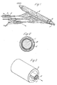
- Figure 1 represents diagrammatically the electrostatic spinning of a liquid onto a former.
- Figure 2 is a cross-section of the mandrel/sheath/prosthesis.
- Figure 3 shows diagrammatically the removal of the rolled sheath from the lumen of the prosthesis.
- The apparatus was as shown diagrammatically in figure 1. The former onto which the fibres were collected consisted of a metal mandrel or core (1) 20 mm in diameter and 25 cm long having a sheath of aluminium foil (2) 0.02 mm and 20 cm long wrapped around it. The former, which was charged to 50 Kv, was rotated about its long axis at about 300 rpm.
- The fibre forming material (3) was fed into the electric field surrounding the former from a bank of 3 syringes (4), the needles of which were 3 cm long and 0.05 cm I.D. at the rate of 1 gm/hr/needle. The fibre forming material was a 15% solution polyether urethane block copolymer in DMF/Butanone (3:2 w/w) solution. The dried solid polymer had a hardness within the range 30-40° shore D.
- Upon introduction of the polymer into the electric field the droplet instantly disintegrated into fibres which were drawn to the mandrel, (over a distance of 10 cm against a counter current of air at 40°C moving at about 25 cm/sec and deposited upon it in a tubular layer (5).
- After allowing the layer to attain a thickness of about 2 mm the process was stopped, the former was removed from the apparatus, the aluminium sheath and product slid off the mandrel and the long edge of the sheath gripped between rods (6) inserted into the lumen of the tube and the sheath rolled more tightly upon the rods and removed from the lumen of the fibrous tube (see Figure 3).
- The process of Example 1 was repeated, except that the outside of the aluminium foil sheath was coated with PTFE spray-on release agent which facilitated release of the fibrous tube, the I.D. of the product obtained was 4 mm the wall thickness was 0.5 mm, spinning being effected through a bank of 3 needles, each delivering 1 gm of solution/hour.
Claims (10)
Applications Claiming Priority (2)
| Application Number | Priority Date | Filing Date | Title |
|---|---|---|---|
| GB1541978 | 1978-04-19 | ||
| GB1541978 | 1978-04-19 |
Publications (2)
| Publication Number | Publication Date |
|---|---|
| EP0005035A1 EP0005035A1 (en) | 1979-10-31 |
| EP0005035B1 true EP0005035B1 (en) | 1981-09-23 |
Family
ID=10058809
Family Applications (1)
| Application Number | Title | Priority Date | Filing Date |
|---|---|---|---|
| EP79300612A Expired EP0005035B1 (en) | 1978-04-19 | 1979-04-12 | A method of preparing a tubular product by electrostatic spinning |
Country Status (6)
| Country | Link |
|---|---|
| US (1) | US4323525A (en) |
| EP (1) | EP0005035B1 (en) |
| JP (1) | JPS54151675A (en) |
| AU (1) | AU529520B2 (en) |
| CA (1) | CA1125968A (en) |
| DE (1) | DE2960875D1 (en) |
Cited By (1)
| Publication number | Priority date | Publication date | Assignee | Title |
|---|---|---|---|---|
| US8017061B2 (en) | 2004-05-28 | 2011-09-13 | Philipps-Universitat Marburg | Invention concerning agricultural active substances |
Families Citing this family (226)
| Publication number | Priority date | Publication date | Assignee | Title |
|---|---|---|---|---|
| DE2965672D1 (en) * | 1978-10-10 | 1983-07-21 | Ici Plc | Production of electrostatically spun products |
| EP0011437B1 (en) * | 1978-11-20 | 1983-06-22 | Imperial Chemical Industries Plc | A process for setting a product comprising electrostatically spun fibres, and products prepared according to this process |
| US4475972A (en) * | 1981-10-01 | 1984-10-09 | Ontario Research Foundation | Implantable material |
| GB2121286B (en) * | 1982-06-02 | 1985-11-06 | Ethicon Inc | Improvements in synthetic vascular grafts, and methods of manufacturing such grafts |
| GB2120946B (en) * | 1982-06-02 | 1985-11-06 | Ethicon Inc | Improvements in synthetic vascular grafts |
| US5110852A (en) * | 1982-07-16 | 1992-05-05 | Rijksuniversiteit Te Groningen | Filament material polylactide mixtures |
| NL8202894A (en) * | 1982-07-16 | 1984-02-16 | Rijksuniversiteit | POLYESTER FILAMENT MATERIAL. |
| GB2142870B (en) * | 1983-07-06 | 1986-06-04 | Ethicon Inc | Manufacturing vascular prostheses by electrostatic spinning |
| US4629458A (en) * | 1985-02-26 | 1986-12-16 | Cordis Corporation | Reinforcing structure for cardiovascular graft |
| US4738740A (en) * | 1985-11-21 | 1988-04-19 | Corvita Corporation | Method of forming implantable vascular grafts |
| US4743252A (en) * | 1986-01-13 | 1988-05-10 | Corvita Corporation | Composite grafts |
| GB2189738B (en) * | 1986-03-24 | 1989-11-15 | Ethicon Inc | Apparatus for producing fibrous structures electrostatically |
| JPS62263361A (en) * | 1986-05-09 | 1987-11-16 | 東レ株式会社 | Production of nonwoven fabric |
| JP2729625B2 (en) * | 1988-03-16 | 1998-03-18 | コービタ、コーポレイション | Method for producing an implantable artificial blood vessel |
| JPH01151767U (en) * | 1988-04-04 | 1989-10-19 | ||
| US4965110A (en) * | 1988-06-20 | 1990-10-23 | Ethicon, Inc. | Electrostatically produced structures and methods of manufacturing |
| US5024671A (en) * | 1988-09-19 | 1991-06-18 | Baxter International Inc. | Microporous vascular graft |
| US5024789A (en) * | 1988-10-13 | 1991-06-18 | Ethicon, Inc. | Method and apparatus for manufacturing electrostatically spun structure |
| US4927410A (en) * | 1988-11-18 | 1990-05-22 | University Of South Florida | Method for fabricating prosthesis material |
| AU650700B2 (en) * | 1991-03-08 | 1994-06-30 | Keiji Igaki | Luminal stent, holding structure therefor and device for attaching luminal stent |
| US5376117A (en) * | 1991-10-25 | 1994-12-27 | Corvita Corporation | Breast prostheses |
| US5866217A (en) * | 1991-11-04 | 1999-02-02 | Possis Medical, Inc. | Silicone composite vascular graft |
| JP3739411B2 (en) * | 1992-09-08 | 2006-01-25 | 敬二 伊垣 | Vascular stent, manufacturing method thereof, and vascular stent device |
| US5300115A (en) * | 1992-11-19 | 1994-04-05 | Keratos, Inc. | Intraocular prosthesis |
| GB9225098D0 (en) | 1992-12-01 | 1993-01-20 | Coffee Ronald A | Charged droplet spray mixer |
| US5716395A (en) * | 1992-12-11 | 1998-02-10 | W.L. Gore & Associates, Inc. | Prosthetic vascular graft |
| US5628782A (en) * | 1992-12-11 | 1997-05-13 | W. L. Gore & Associates, Inc. | Method of making a prosthetic vascular graft |
| BE1006440A3 (en) * | 1992-12-21 | 1994-08-30 | Dereume Jean Pierre Georges Em | Luminal endoprosthesis AND METHOD OF PREPARATION. |
| US6105571A (en) | 1992-12-22 | 2000-08-22 | Electrosols, Ltd. | Dispensing device |
| US5639278A (en) * | 1993-10-21 | 1997-06-17 | Corvita Corporation | Expandable supportive bifurcated endoluminal grafts |
| US5855598A (en) * | 1993-10-21 | 1999-01-05 | Corvita Corporation | Expandable supportive branched endoluminal grafts |
| US5632772A (en) | 1993-10-21 | 1997-05-27 | Corvita Corporation | Expandable supportive branched endoluminal grafts |
| US5723004A (en) * | 1993-10-21 | 1998-03-03 | Corvita Corporation | Expandable supportive endoluminal grafts |
| US6334872B1 (en) | 1994-02-18 | 2002-01-01 | Organogenesis Inc. | Method for treating diseased or damaged organs |
| EP0689805B1 (en) * | 1994-06-27 | 2003-05-28 | Corvita Corporation | Bistable luminal graft endoprostheses |
| US20020095218A1 (en) * | 1996-03-12 | 2002-07-18 | Carr Robert M. | Tissue repair fabric |
| BE1010183A3 (en) | 1996-04-25 | 1998-02-03 | Dereume Jean Pierre Georges Em | Luminal endoprosthesis FOR BRANCHING CHANNELS OF A HUMAN OR ANIMAL BODY AND MANUFACTURING METHOD THEREOF. |
| US6252129B1 (en) | 1996-07-23 | 2001-06-26 | Electrosols, Ltd. | Dispensing device and method for forming material |
| US20080119772A1 (en) | 2001-01-11 | 2008-05-22 | Ronald Alan Coffee | Dispensing device and method for forming material |
| CA2296334C (en) * | 1996-07-23 | 2010-03-16 | Electrosols Ltd. | A dispensing device and method for forming material |
| US7193124B2 (en) | 1997-07-22 | 2007-03-20 | Battelle Memorial Institute | Method for forming material |
| US5824047A (en) * | 1996-10-11 | 1998-10-20 | C. R. Bard, Inc. | Vascular graft fabric |
| US5931865A (en) * | 1997-11-24 | 1999-08-03 | Gore Enterprise Holdings, Inc. | Multiple-layered leak resistant tube |
| DE69940507D1 (en) * | 1998-06-05 | 2009-04-16 | Organogenesis Inc | BIOTECHNICALLY GENERATED VASCOPY THERAPY FOR IMPLANTATION |
| WO1999063051A2 (en) * | 1998-06-05 | 1999-12-09 | Organogenesis Inc. | Bioengineered flat sheet graft prostheses |
| ATE423577T1 (en) * | 1998-06-05 | 2009-03-15 | Organogenesis Inc | BIOLOGICALLY MODELED IMPLANTABLE PROSTHESES |
| MXPA00012063A (en) * | 1998-06-05 | 2003-04-22 | Organogenesis Inc | Bioengineered vascular graft support prostheses. |
| US7615373B2 (en) | 1999-02-25 | 2009-11-10 | Virginia Commonwealth University Intellectual Property Foundation | Electroprocessed collagen and tissue engineering |
| US6592623B1 (en) | 1999-08-31 | 2003-07-15 | Virginia Commonwealth University Intellectual Property Foundation | Engineered muscle |
| NZ503231A (en) | 1999-03-08 | 2001-09-28 | Humatro Corp | Absorbent, flexible structure comprising pseudo-thermoplastic starch fibers, plasticizer (such as sorbitol, PVA) |
| EP1212107B1 (en) * | 1999-08-31 | 2005-06-08 | Virginia Commonwealth University Intellectual Property Foundation | Engineered muscle |
| US6753454B1 (en) | 1999-10-08 | 2004-06-22 | The University Of Akron | Electrospun fibers and an apparatus therefor |
| EP1315756A2 (en) | 2000-09-01 | 2003-06-04 | Virginia Commonwealth University Intellectual Property Foundation | Electroprocessed fibrin-based matrices and tissues |
| US6716274B2 (en) | 2000-09-05 | 2004-04-06 | Donaldson Company, Inc. | Air filter assembly for filtering an air stream to remove particulate matter entrained in the stream |
| US6746517B2 (en) * | 2000-09-05 | 2004-06-08 | Donaldson Company, Inc. | Filter structure with two or more layers of fine fiber having extended useful service life |
| US7270693B2 (en) * | 2000-09-05 | 2007-09-18 | Donaldson Company, Inc. | Polymer, polymer microfiber, polymer nanofiber and applications including filter structures |
| US6800117B2 (en) | 2000-09-05 | 2004-10-05 | Donaldson Company, Inc. | Filtration arrangement utilizing pleated construction and method |
| US7115150B2 (en) * | 2000-09-05 | 2006-10-03 | Donaldson Company, Inc. | Mist filtration arrangement utilizing fine fiber layer in contact with media having a pleated construction and floor filter method |
| US6673136B2 (en) * | 2000-09-05 | 2004-01-06 | Donaldson Company, Inc. | Air filtration arrangements having fluted media constructions and methods |
| US6740142B2 (en) | 2000-09-05 | 2004-05-25 | Donaldson Company, Inc. | Industrial bag house elements |
| US20020092423A1 (en) * | 2000-09-05 | 2002-07-18 | Gillingham Gary R. | Methods for filtering air for a gas turbine system |
| US6743273B2 (en) | 2000-09-05 | 2004-06-01 | Donaldson Company, Inc. | Polymer, polymer microfiber, polymer nanofiber and applications including filter structures |
| CA2422852C (en) * | 2000-09-18 | 2012-06-26 | Organogenesis Inc. | Methods for treating a patient using a bioengineered flat sheet graft prostheses |
| WO2002032397A2 (en) * | 2000-10-18 | 2002-04-25 | Virginia Commonwealth University Intellectual Property Foundation | Electroprocessing in drug delivery and cell encapsulation |
| DE10053263A1 (en) * | 2000-10-26 | 2002-05-08 | Creavis Tech & Innovation Gmbh | Oriented meso and nanotube fleece |
| US20020084178A1 (en) * | 2000-12-19 | 2002-07-04 | Nicast Corporation Ltd. | Method and apparatus for manufacturing polymer fiber shells via electrospinning |
| US20070031607A1 (en) * | 2000-12-19 | 2007-02-08 | Alexander Dubson | Method and apparatus for coating medical implants |
| US20040030377A1 (en) * | 2001-10-19 | 2004-02-12 | Alexander Dubson | Medicated polymer-coated stent assembly |
| US7244272B2 (en) | 2000-12-19 | 2007-07-17 | Nicast Ltd. | Vascular prosthesis and method for production thereof |
| ATE473082T1 (en) * | 2001-03-20 | 2010-07-15 | Nicast Ltd | PORTABLE ELECTROSPINNER DEVICE |
| DE10116232A1 (en) | 2001-04-02 | 2002-10-10 | Creavis Tech & Innovation Gmbh | Molded articles with internally coated cavities, useful as e.g. sensors, are prepared by forming template fibers with selective removal of material |
| US6713011B2 (en) | 2001-05-16 | 2004-03-30 | The Research Foundation At State University Of New York | Apparatus and methods for electrospinning polymeric fibers and membranes |
| US6685956B2 (en) | 2001-05-16 | 2004-02-03 | The Research Foundation At State University Of New York | Biodegradable and/or bioabsorbable fibrous articles and methods for using the articles for medical applications |
| RU2300543C2 (en) * | 2001-05-31 | 2007-06-10 | Дональдсон Компани, Инк. | Fine fiber compositions, methods for preparation thereof, and a method of manufacturing fine-fiber material |
| US6821479B1 (en) | 2001-06-12 | 2004-11-23 | The University Of Akron | Preservation of biological materials using fiber-forming techniques |
| US7105124B2 (en) | 2001-06-19 | 2006-09-12 | Aaf-Mcquay, Inc. | Method, apparatus and product for manufacturing nanofiber media |
| DE10133393B4 (en) | 2001-07-13 | 2007-08-30 | TransMIT Gesellschaft für Technologietransfer mbH | Tubes with inside diameters in the nanometer range |
| DE10136256B4 (en) * | 2001-07-25 | 2005-03-31 | Helsa-Werke Gmbh & Co. Kg | Apparatus for producing fibers in an electrostatic spinning process |
| US6790455B2 (en) * | 2001-09-14 | 2004-09-14 | The Research Foundation At State University Of New York | Cell delivery system comprising a fibrous matrix and cells |
| US7309498B2 (en) * | 2001-10-10 | 2007-12-18 | Belenkaya Bronislava G | Biodegradable absorbents and methods of preparation |
| US7390452B2 (en) * | 2002-03-08 | 2008-06-24 | Board Of Regents, The University Of Texas System | Electrospinning of polymer and mesoporous composite fibers |
| US20030211135A1 (en) * | 2002-04-11 | 2003-11-13 | Greenhalgh Skott E. | Stent having electrospun covering and method |
| US20040051201A1 (en) * | 2002-04-11 | 2004-03-18 | Greenhalgh Skott E. | Coated stent and method for coating by treating an electrospun covering with heat or chemicals |
| US20030195611A1 (en) * | 2002-04-11 | 2003-10-16 | Greenhalgh Skott E. | Covering and method using electrospinning of very small fibers |
| US20050187605A1 (en) * | 2002-04-11 | 2005-08-25 | Greenhalgh Skott E. | Electrospun skin capable of controlling drug release rates and method |
| US7270675B2 (en) * | 2002-05-10 | 2007-09-18 | Cordis Corporation | Method of forming a tubular membrane on a structural frame |
| WO2003094795A1 (en) * | 2002-05-10 | 2003-11-20 | Cordis Corporation | Method of making a medical device having a thin wall tubular membrane over a structural frame |
| US7485141B2 (en) * | 2002-05-10 | 2009-02-03 | Cordis Corporation | Method of placing a tubular membrane on a structural frame |
| US7351256B2 (en) * | 2002-05-10 | 2008-04-01 | Cordis Corporation | Frame based unidirectional flow prosthetic implant |
| EP1509256B1 (en) | 2002-05-24 | 2009-07-22 | Angiotech International Ag | Compositions and methods for coating medical implants |
| US7794833B2 (en) * | 2002-06-21 | 2010-09-14 | Board Of Regents, The University Of Texas System | Electrospun mesoporous molecular sieve fibers |
| GB0223870D0 (en) * | 2002-10-14 | 2002-11-20 | Cathnet Science Holding As | Stent assembly |
| KR101088656B1 (en) * | 2003-03-31 | 2011-12-01 | 데이진 가부시키가이샤 | Molded elastin article and process for producing the same |
| US20040230289A1 (en) * | 2003-05-15 | 2004-11-18 | Scimed Life Systems, Inc. | Sealable attachment of endovascular stent to graft |
| WO2004110304A2 (en) * | 2003-05-29 | 2004-12-23 | Secor Medical, Llc | Filament based prosthesis |
| US7517479B2 (en) * | 2003-12-04 | 2009-04-14 | Bango Joseph J | Method of utilizing MEMS based devices to produce electrospun fibers for commercial, industrial and medical use |
| WO2005063305A1 (en) * | 2003-12-22 | 2005-07-14 | Bracco Research Sa | Gas-filled microvesicle assembly for contrast imaging |
| US20080200975A1 (en) * | 2004-01-06 | 2008-08-21 | Nicast Ltd. | Vascular Prosthesis with Anastomotic Member |
| EP1725703B1 (en) * | 2004-03-16 | 2009-06-10 | University Of Delaware | Active and adaptive photochromic fibers,textiles and membranes |
| US20070141333A1 (en) * | 2004-03-25 | 2007-06-21 | Shastri Venkatram P | Emulsion-based control of electrospun fiber morphology |
| US7134857B2 (en) * | 2004-04-08 | 2006-11-14 | Research Triangle Institute | Electrospinning of fibers using a rotatable spray head |
| US7592277B2 (en) * | 2005-05-17 | 2009-09-22 | Research Triangle Institute | Nanofiber mats and production methods thereof |
| US7762801B2 (en) * | 2004-04-08 | 2010-07-27 | Research Triangle Institute | Electrospray/electrospinning apparatus and method |
| US7297305B2 (en) | 2004-04-08 | 2007-11-20 | Research Triangle Institute | Electrospinning in a controlled gaseous environment |
| US7553377B1 (en) * | 2004-04-27 | 2009-06-30 | Advanced Cardiovascular Systems, Inc. | Apparatus and method for electrostatic coating of an abluminal stent surface |
| JP2007534389A (en) * | 2004-04-29 | 2007-11-29 | キューブ・メディカル・アクティーゼルスカブ | Balloon used for angiogenesis |
| JP4448946B2 (en) | 2004-05-20 | 2010-04-14 | 国立大学法人山梨大学 | A method for producing vinyl-based conductive polymer fibers, and a vinyl-based conductive polymer fiber obtained by the method. |
| US7856989B2 (en) * | 2004-12-30 | 2010-12-28 | Philip Morris Usa Inc. | Electrostatically produced fast dissolving fibers |
| US8367639B2 (en) * | 2005-03-31 | 2013-02-05 | University Of Delaware | Hydrogels with covalent and noncovalent crosslinks |
| US7737131B2 (en) * | 2005-03-31 | 2010-06-15 | University Of Delaware | Multifunctional and biologically active matrices from multicomponent polymeric solutions |
| US7732427B2 (en) * | 2005-03-31 | 2010-06-08 | University Of Delaware | Multifunctional and biologically active matrices from multicomponent polymeric solutions |
| US8415325B2 (en) * | 2005-03-31 | 2013-04-09 | University Of Delaware | Cell-mediated delivery and targeted erosion of noncovalently crosslinked hydrogels |
| JP4695430B2 (en) * | 2005-04-12 | 2011-06-08 | 帝人株式会社 | Cylindrical body and method of manufacturing the cylindrical body |
| EP2476756A1 (en) * | 2005-06-15 | 2012-07-18 | Massachusetts Institute of Technology | Amine-containing lipids and uses thereof |
| WO2007002933A2 (en) * | 2005-06-28 | 2007-01-04 | Stout Medical Group, Inc. | Micro-thin film structures for cardiovascular indications |
| EP1741463A1 (en) | 2005-07-05 | 2007-01-10 | Millimed A/S | A guiding and an embolization catheter |
| JP4653617B2 (en) * | 2005-09-28 | 2011-03-16 | 帝人株式会社 | Method and apparatus for producing fiber structure by electrospinning method |
| US8083983B2 (en) * | 2005-11-28 | 2011-12-27 | Rabolt John F | Method of solution preparation of polyolefin class polymers for electrospinning processing included |
| CN100464015C (en) * | 2006-02-24 | 2009-02-25 | 苏州大学 | Machine for spinning nano-fiber for production of non-woven cloth |
| CN1876902B (en) * | 2006-07-10 | 2010-05-26 | 东华大学 | Atmosphere controllable static spinning device and method |
| AU2007281553B2 (en) | 2006-07-31 | 2013-09-19 | Edwards Lifesciences Cardiaq Llc | Sealable endovascular implants and methods for their use |
| US9585743B2 (en) | 2006-07-31 | 2017-03-07 | Edwards Lifesciences Cardiaq Llc | Surgical implant devices and methods for their manufacture and use |
| US9408607B2 (en) * | 2009-07-02 | 2016-08-09 | Edwards Lifesciences Cardiaq Llc | Surgical implant devices and methods for their manufacture and use |
| HUE032652T2 (en) * | 2006-09-14 | 2017-10-30 | Federal-Mogul Deva Gmbh | Pivot bearing with plastic outer ring and method for its manufacture |
| JP2008078476A (en) * | 2006-09-22 | 2008-04-03 | Hitachi Cable Ltd | Electromagnetic wave shielding material, coaxial cable using the same, and method for manufacturing the coaxial cable |
| WO2008055038A2 (en) * | 2006-10-30 | 2008-05-08 | Rutgers, The State University | Electrospun matrices for delivery of hydrophilic and lidophilic compounds |
| US9175422B2 (en) * | 2007-01-22 | 2015-11-03 | The United States Of America As Represented By The Secretary Of The Army | Polymer-micelle complex as an aid to electrospinning |
| US20090042029A1 (en) * | 2007-04-13 | 2009-02-12 | Drexel University | Polyamide nanofibers and methods thereof |
| US20090326128A1 (en) * | 2007-05-08 | 2009-12-31 | Javier Macossay-Torres | Fibers and methods relating thereto |
| DE102007027014A1 (en) | 2007-06-08 | 2008-12-18 | Rainer Busch | Spinning nano- and micro-fibers, rapidly accelerates stratified polymers and polymer solutions whilst applying electrical field to modify physical- and surface properties |
| US20100331957A1 (en) * | 2007-06-11 | 2010-12-30 | Nanovasc, Inc. | Implantable medical device |
| US20100070020A1 (en) | 2008-06-11 | 2010-03-18 | Nanovasc, Inc. | Implantable Medical Device |
| CA2692143C (en) * | 2007-06-19 | 2015-07-07 | Abdellah Ajji | Non-woven mat and method of producing same |
| CN100549247C (en) * | 2007-06-26 | 2009-10-14 | 华南理工大学 | Minitype continuous electrostatic spinning molding equipment |
| US9814611B2 (en) | 2007-07-31 | 2017-11-14 | Edwards Lifesciences Cardiaq Llc | Actively controllable stent, stent graft, heart valve and method of controlling same |
| US9566178B2 (en) | 2010-06-24 | 2017-02-14 | Edwards Lifesciences Cardiaq Llc | Actively controllable stent, stent graft, heart valve and method of controlling same |
| US20090091065A1 (en) * | 2007-10-09 | 2009-04-09 | Indian Institute Of Technology Kanpur | Electrospinning Apparatus For Producing Nanofibers and Process Thereof |
| CZ2007729A3 (en) * | 2007-10-18 | 2009-04-29 | Elmarco S. R. O. | Apparatus for producing a layer of nanofibers by electrostatic spinning of polymer matrices and collecting electrode for such an apparatus |
| US7901611B2 (en) * | 2007-11-28 | 2011-03-08 | The United States Of America As Represented By The Administrator Of The National Aeronautics And Space Administration | Method for predicting and optimizing system parameters for electrospinning system |
| US8795577B2 (en) | 2007-11-30 | 2014-08-05 | Cook Medical Technologies Llc | Needle-to-needle electrospinning |
| CA2718897A1 (en) * | 2008-03-17 | 2009-09-17 | The Board Of Regents Of The University Of Texas System | Superfine fiber creating spinneret and uses thereof |
| CN101559243A (en) * | 2008-04-18 | 2009-10-21 | 中国科学院上海硅酸盐研究所 | Preparation method of tubular electrospinning fibre material |
| JP5007474B2 (en) * | 2008-06-09 | 2012-08-22 | パナソニック株式会社 | Non-bonded cylinder manufacturing apparatus, non-bonded cylinder manufacturing method |
| EP2962704A1 (en) | 2008-10-07 | 2016-01-06 | Nanonerve, Inc. | Multilayer fibrous polymer scaffolds, methods of production and methods of use |
| WO2010053572A2 (en) | 2008-11-07 | 2010-05-14 | Massachusetts Institute Of Technology | Aminoalcohol lipidoids and uses thereof |
| US20130268062A1 (en) | 2012-04-05 | 2013-10-10 | Zeus Industrial Products, Inc. | Composite prosthetic devices |
| US8178030B2 (en) * | 2009-01-16 | 2012-05-15 | Zeus Industrial Products, Inc. | Electrospinning of PTFE with high viscosity materials |
| US9750829B2 (en) | 2009-03-19 | 2017-09-05 | Emd Millipore Corporation | Removal of microorganisms from fluid samples using nanofiber filtration media |
| IT1394605B1 (en) * | 2009-06-05 | 2012-07-05 | Chiellini | PROCEDURE AND DEVICE FOR THE PRODUCTION OF TUBULAR STRUCTURES IN POLYMERIC THERMOPLASTIC MATERIALS. |
| JP2013501539A (en) | 2009-08-07 | 2013-01-17 | ゼウス インダストリアル プロダクツ インコーポレイテッド | Prosthetic device comprising an electrospun fiber layer and method for producing the same |
| US20110038936A1 (en) * | 2009-08-17 | 2011-02-17 | Kimberly Ann Griswold | System and method for electrospun drug loaded biodegradable chemotherapy applications |
| AU2010326132B9 (en) | 2009-12-01 | 2014-10-02 | Translate Bio, Inc. | Delivery of mRNA for the augmentation of proteins and enzymes in human genetic diseases |
| US8637109B2 (en) * | 2009-12-03 | 2014-01-28 | Cook Medical Technologies Llc | Manufacturing methods for covering endoluminal prostheses |
| WO2011082295A2 (en) * | 2009-12-31 | 2011-07-07 | Neograft Technologies, Inc. | Graft devices and methods of fabrication |
| CZ201093A3 (en) * | 2010-02-05 | 2011-08-17 | Cpn S.R.O. | Device for producing two-dimensional or three-dimensional fibrous materials from microfibers or nanofibers |
| US8377365B2 (en) * | 2010-04-29 | 2013-02-19 | Medtronic Vascular, Inc. | System and method for stent manufacture |
| DE102010025302B4 (en) | 2010-06-28 | 2012-09-13 | Gottfried Wilhelm Leibniz Universität Hannover | Method of making a stent with electrospun fiber coating |
| WO2012003300A2 (en) * | 2010-07-02 | 2012-01-05 | The Procter & Gamble Company | Filaments comprising a non-perfume active agent nonwoven webs and methods for making same |
| MX2012015187A (en) | 2010-07-02 | 2013-05-09 | Procter & Gamble | Method for delivering an active agent. |
| MX2012015174A (en) | 2010-07-02 | 2013-05-09 | Procter & Gamble | Filaments comprising an active agent nonwoven webs and methods for making same. |
| CA2803636C (en) | 2010-07-02 | 2017-05-16 | The Procter & Gamble Company | Detergent product and method for making same |
| EP2595695B1 (en) | 2010-07-19 | 2019-02-06 | Neograft Technologies, Inc. | Graft devices and methods of use |
| WO2012021308A2 (en) | 2010-08-10 | 2012-02-16 | Millipore Corporation | Method for retrovirus removal |
| EP2609135A4 (en) | 2010-08-26 | 2015-05-20 | Massachusetts Inst Technology | Poly(beta-amino alcohols), their preparation, and uses thereof |
| EP2563956A4 (en) | 2010-10-14 | 2013-09-18 | Zeus Ind Products Inc | Antimicrobial substrate |
| EP2646065A4 (en) | 2010-12-05 | 2016-03-23 | Nanonerve Inc | Fibrous polymer scaffolds having diametrically patterned polymer fibers |
| US10085829B2 (en) | 2011-01-14 | 2018-10-02 | Neograft Technologies, Inc. | Apparatus for creating graft devices |
| JP6203639B2 (en) | 2011-01-28 | 2017-09-27 | メリット・メディカル・システムズ・インコーポレイテッドMerit Medical Systems,Inc. | Electrospun PTFE coated stent and method of use |
| US8658067B2 (en) | 2011-02-07 | 2014-02-25 | Fiberio Technology Corporation | Apparatuses and methods for the deposition of microfibers and nanofibers on a substrate |
| WO2012109309A2 (en) | 2011-02-09 | 2012-08-16 | Neograft Technologies, Inc. | System and mandrel for creating graft devices |
| DK2691443T3 (en) | 2011-03-28 | 2021-05-03 | Massachusetts Inst Technology | CONJUGIATED LIPOMERS AND USES OF THESE |
| US20130190805A1 (en) * | 2011-03-31 | 2013-07-25 | DePuy Synthes Products, LLC | Method of fabricating modifiable occlusion device |
| CN105413480B (en) | 2011-04-01 | 2019-03-29 | Emd密理博公司 | Composite structure containing nanofiber |
| KR102128248B1 (en) | 2011-06-08 | 2020-07-01 | 샤이어 휴먼 지네틱 테라피즈 인크. | Lipid nanoparticle compositions and methods for mrna delivery |
| DE102011109767A1 (en) | 2011-08-09 | 2013-02-14 | Mann + Hummel Gmbh | Process for the production of polyamide nanofibers by electrospinning, polyamide nanofibers, a filter medium with polyamide nanofibers and a filter element with such a filter medium |
| CN102358959B (en) * | 2011-08-16 | 2013-11-06 | 中山大学 | Method and device for preparing electrospinning fiber bracket with three-dimensional structure |
| US9827093B2 (en) | 2011-10-21 | 2017-11-28 | Edwards Lifesciences Cardiaq Llc | Actively controllable stent, stent graft, heart valve and method of controlling same |
| US9175427B2 (en) | 2011-11-14 | 2015-11-03 | Cook Medical Technologies Llc | Electrospun patterned stent graft covering |
| WO2013090337A1 (en) * | 2011-12-13 | 2013-06-20 | Neograft Technologies, Inc. | System and atraumatic mandrel for creating graft devices |
| CN104114201A (en) | 2012-01-16 | 2014-10-22 | 美国医疗设备有限公司 | Rotational spun material covered medical appliances and methods of manufacture |
| US20130197664A1 (en) | 2012-01-27 | 2013-08-01 | Zeus Industrial Products, Inc. | Electrospun Porous Media |
| CN104203151A (en) * | 2012-02-14 | 2014-12-10 | 尼奥格拉夫特科技公司 | Kink resistant graft devices and related systems and methods |
| US9775933B2 (en) | 2012-03-02 | 2017-10-03 | W. L. Gore & Associates, Inc. | Biocompatible surfaces and devices incorporating such surfaces |
| PL231639B1 (en) | 2012-04-17 | 2019-03-29 | Politechnika Lodzka | Medical material for the reconstruction of blood vessels, a method for producing the medical material and medical material applied to the reconstruction of blood vessels |
| US20150267192A1 (en) | 2012-06-08 | 2015-09-24 | Shire Human Genetic Therapies, Inc. | Nuclease resistant polynucleotides and uses thereof |
| WO2014025790A1 (en) | 2012-08-06 | 2014-02-13 | Fiberio Technology Corporation | Systems and methods of heating a fiber producing device |
| EP2882706A1 (en) | 2012-08-13 | 2015-06-17 | Massachusetts Institute of Technology | Amine-containing lipidoids and uses thereof |
| US10507268B2 (en) | 2012-09-19 | 2019-12-17 | Merit Medical Systems, Inc. | Electrospun material covered medical appliances and methods of manufacture |
| US9198999B2 (en) | 2012-09-21 | 2015-12-01 | Merit Medical Systems, Inc. | Drug-eluting rotational spun coatings and methods of use |
| US9091007B2 (en) * | 2012-12-10 | 2015-07-28 | Taipei Medical University | Electrospinning apparatus with a sideway motion device and a method of using the same |
| US10154918B2 (en) | 2012-12-28 | 2018-12-18 | Cook Medical Technologies Llc | Endoluminal prosthesis with fiber matrix |
| US20140205781A1 (en) * | 2013-01-23 | 2014-07-24 | Zeus Industrial Products, Inc. | Silicone espun ptfe composites |
| EP3988278A1 (en) | 2013-03-13 | 2022-04-27 | Merit Medical Systems, Inc. | Serially deposited fiber materials and associated devices and methods |
| US9827703B2 (en) | 2013-03-13 | 2017-11-28 | Merit Medical Systems, Inc. | Methods, systems, and apparatuses for manufacturing rotational spun appliances |
| BR112015022868B1 (en) | 2013-03-14 | 2023-05-16 | Ethris Gmbh | CFTR MRNA COMPOSITIONS AND RELATED USES AND METHODS |
| KR20150128687A (en) | 2013-03-14 | 2015-11-18 | 샤이어 휴먼 지네틱 테라피즈 인크. | Methods for purification of messenger rna |
| WO2014179562A1 (en) | 2013-05-01 | 2014-11-06 | Massachusetts Institute Of Technology | 1,3,5-triazinane-2,4,6-trione derivatives and uses thereof |
| CN103334167B (en) * | 2013-07-11 | 2015-07-01 | 厦门大学 | Microfiber coil electrospinning direct-writing device |
| EP3501605B1 (en) | 2013-10-22 | 2023-06-28 | Translate Bio, Inc. | Mrna therapy for argininosuccinate synthetase deficiency |
| PE20161242A1 (en) | 2013-10-22 | 2016-12-11 | Massachusetts Inst Technology | LIPID FORMULATIONS FOR THE ADMINISTRATION OF MESSENGER RNA |
| EP3060258A1 (en) | 2013-10-22 | 2016-08-31 | Shire Human Genetic Therapies, Inc. | Mrna therapy for phenylketonuria |
| US11000285B2 (en) * | 2013-12-17 | 2021-05-11 | 3Dt Holdings, Llc | Luminal grafts and methods of making and using the same |
| AU2015249312B2 (en) | 2014-04-25 | 2021-07-29 | Translate Bio, Inc. | Methods for purification of messenger RNA |
| AU2015266764B2 (en) | 2014-05-30 | 2019-11-07 | Translate Bio, Inc. | Biodegradable lipids for delivery of nucleic acids |
| WO2015200465A1 (en) | 2014-06-24 | 2015-12-30 | Shire Human Genetic Therapies, Inc. | Stereochemically enriched compositions for delivery of nucleic acids |
| WO2016004202A1 (en) | 2014-07-02 | 2016-01-07 | Massachusetts Institute Of Technology | Polyamine-fatty acid derived lipidoids and uses thereof |
| DE102014109769B4 (en) * | 2014-07-11 | 2018-05-24 | Gottfried Wilhelm Leibniz Universität Hannover | Device and method for producing a vascular prosthesis |
| US10028852B2 (en) | 2015-02-26 | 2018-07-24 | Merit Medical Systems, Inc. | Layered medical appliances and methods |
| SG11201706726TA (en) | 2015-04-17 | 2017-09-28 | Emd Millipore Corp | Method of purifying a biological materia of interest in a sample using nanofiber ultrafiltration membranes operated in tangential flow filtration mode |
| WO2016193105A1 (en) * | 2015-06-01 | 2016-12-08 | Servidis S.A. | Retractable tubular support device for winding trimmings and winding method using said device |
| US10696034B2 (en) * | 2015-12-11 | 2020-06-30 | Massachusetts Institute Of Technology | Systems, devices, and methods for deposition-based three-dimensional printing |
| EP3400132A4 (en) | 2016-01-08 | 2019-08-07 | Clarcor Inc. | Use of microfibers and/or nanofibers in apparel and footwear |
| CN110167639B (en) | 2017-01-27 | 2022-10-14 | 宝洁公司 | Composition in the form of a soluble solid structure comprising effervescent agglomerated granules |
| EP3585417B1 (en) | 2017-02-27 | 2023-02-22 | Translate Bio, Inc. | Method of making a codon-optimized cftr mrna |
| CA3063531A1 (en) | 2017-05-16 | 2018-11-22 | Translate Bio, Inc. | Treatment of cystic fibrosis by delivery of codon-optimized mrna encoding cftr |
| CA3074944A1 (en) | 2017-09-08 | 2019-03-14 | Board Of Regents Of The University Of Texas System | Mechanoluminescence polymer doped fabrics and methods of making |
| CN108577916B (en) * | 2018-03-08 | 2020-10-23 | 戴庆涛 | Preparation method of anastomat for gastrointestinal surgery |
| WO2020041793A1 (en) | 2018-08-24 | 2020-02-27 | Translate Bio, Inc. | Methods for purification of messenger rna |
| US11666514B2 (en) | 2018-09-21 | 2023-06-06 | The Procter & Gamble Company | Fibrous structures containing polymer matrix particles with perfume ingredients |
| CN109440302A (en) * | 2018-10-31 | 2019-03-08 | 大连理工大学 | With the alkaline electrolyte membrane for leading directly to orderly hydroxide ion conduction pathway |
| US11427937B2 (en) | 2019-02-20 | 2022-08-30 | The Board Of Regents Of The University Of Texas System | Handheld/portable apparatus for the production of microfibers, submicron fibers and nanofibers |
| JP7381613B2 (en) | 2019-06-28 | 2023-11-15 | ザ プロクター アンド ギャンブル カンパニー | Dissolvable solid fibrous article containing anionic surfactant |
| KR20210083461A (en) * | 2019-12-26 | 2021-07-07 | 삼성디스플레이 주식회사 | Apparatus for manufacturing conductive film and method of manufacturing conductive film |
| CN111150522A (en) * | 2019-12-31 | 2020-05-15 | 武汉杨森生物技术有限公司 | Artificial blood vessel with fiber orientation composite structure and preparation method thereof |
| WO2022027067A1 (en) | 2020-07-31 | 2022-02-03 | The Procter & Gamble Company | Water-soluble fibrous pouch containing prills for hair care |
| JP2022178046A (en) * | 2021-05-19 | 2022-12-02 | パナソニックIpマネジメント株式会社 | Manufacturing apparatus and manufacturing method of fiber assembly |
Family Cites Families (7)
| Publication number | Priority date | Publication date | Assignee | Title |
|---|---|---|---|---|
| US2241125A (en) * | 1937-04-07 | 1941-05-06 | Girard Emile Gustave Louis | Molding device with extensible core |
| US3851838A (en) * | 1970-06-22 | 1974-12-03 | W Biggs | Slip sleeves |
| JPS5056413A (en) * | 1973-09-21 | 1975-05-17 | ||
| US3910513A (en) * | 1973-10-18 | 1975-10-07 | Owens Corning Fiberglass Corp | Collection tubes for rotary collection of filamentary material |
| GB1527592A (en) * | 1974-08-05 | 1978-10-04 | Ici Ltd | Wound dressing |
| GB1522605A (en) * | 1974-09-26 | 1978-08-23 | Ici Ltd | Preparation of fibrous sheet product |
| GB1577221A (en) * | 1976-02-04 | 1980-10-22 | Ici Ltd | Vascular prosthesis |
-
1979
- 1979-04-12 DE DE7979300612T patent/DE2960875D1/en not_active Expired
- 1979-04-12 EP EP79300612A patent/EP0005035B1/en not_active Expired
- 1979-04-18 AU AU46190/79A patent/AU529520B2/en not_active Ceased
- 1979-04-19 JP JP4850779A patent/JPS54151675A/en active Granted
- 1979-04-19 US US06/031,606 patent/US4323525A/en not_active Expired - Lifetime
- 1979-04-19 CA CA325,914A patent/CA1125968A/en not_active Expired
Cited By (2)
| Publication number | Priority date | Publication date | Assignee | Title |
|---|---|---|---|---|
| US8017061B2 (en) | 2004-05-28 | 2011-09-13 | Philipps-Universitat Marburg | Invention concerning agricultural active substances |
| US8431064B2 (en) | 2004-05-28 | 2013-04-30 | Phillips-Universitat Marburg | Method of using nanoscaled polymer fibers as carriers for agricultural substances |
Also Published As
| Publication number | Publication date |
|---|---|
| EP0005035A1 (en) | 1979-10-31 |
| JPS63543B2 (en) | 1988-01-07 |
| CA1125968A (en) | 1982-06-22 |
| JPS54151675A (en) | 1979-11-29 |
| DE2960875D1 (en) | 1981-12-10 |
| AU529520B2 (en) | 1983-06-09 |
| US4323525A (en) | 1982-04-06 |
| AU4619079A (en) | 1979-10-25 |
Similar Documents
| Publication | Publication Date | Title |
|---|---|---|
| EP0005035B1 (en) | A method of preparing a tubular product by electrostatic spinning | |
| US4345414A (en) | Shaping process | |
| US4878908A (en) | Fibrillar product | |
| US4127706A (en) | Porous fluoropolymeric fibrous sheet and method of manufacture | |
| US8337742B2 (en) | Bubble launched electrospinning jets | |
| CN101595251B (en) | Microtubes and methods of producing same | |
| EP0009941B2 (en) | Production of electrostatically spun products | |
| KR101092271B1 (en) | Nonwoven fabric and process for producing the same | |
| WO2010083530A2 (en) | Electrospinning of ptfe with high viscosity materials | |
| WO2002049678A2 (en) | Method and apparatus for manufacturing polymer fiber shells via electrospinning | |
| JP2004531652A (en) | Polymer fiber tubular structures with improved resistance to kink formation | |
| GB1577221A (en) | Vascular prosthesis | |
| US20060148978A1 (en) | Polymer structures formed on fibers and/or nanofiber | |
| Kanawung et al. | Preparation and characterization of polycaprolactone/diclofenac sodium and poly (vinyl alcohol)/tetracycline hydrochloride fiber mats and their release of the model drugs | |
| Bowlin et al. | Electrospinning of polymer scaffolds for tissue engineering | |
| EP0010865B1 (en) | Product adapted for transcutaneous use | |
| US8574315B2 (en) | Electrospun structures and methods for forming and using same | |
| JP2004290133A (en) | Cell culture substrate and method for producing the same | |
| KR101112649B1 (en) | A composite porous continuous membrane and its producing method | |
| CH641541A5 (en) | Method for producing a tubular product, by electrostatic spinning of a fibre-forming material | |
| Snetkov et al. | The influence of technological parameters on morphology of electrospun nanofibers based on hyaluronic acid | |
| EP2997059A1 (en) | Process for the production of poly(cyanoacrylate) fibres | |
| Hsu | Electrospinning of Poly ([epsilon]-Caprolactone). | |
| CN113550067A (en) | Method for manufacturing porous anti-adhesive film | |
| JPH0691889B2 (en) | Manufacturing method of artificial blood vessel |
Legal Events
| Date | Code | Title | Description |
|---|---|---|---|
| PUAI | Public reference made under article 153(3) epc to a published international application that has entered the european phase |
Free format text: ORIGINAL CODE: 0009012 |
|
| AK | Designated contracting states |
Designated state(s): DE FR GB IT NL SE |
|
| 17P | Request for examination filed | ||
| ITF | It: translation for a ep patent filed |
Owner name: ING. C. GREGORJ S.P.A. |
|
| GRAA | (expected) grant |
Free format text: ORIGINAL CODE: 0009210 |
|
| AK | Designated contracting states |
Designated state(s): DE FR GB IT NL SE |
|
| REF | Corresponds to: |
Ref document number: 2960875 Country of ref document: DE Date of ref document: 19811210 |
|
| RAP2 | Party data changed (patent owner data changed or rights of a patent transferred) |
Owner name: UNIVERSITY OF LIVERPOOL Owner name: IMPERIAL CHEMICAL INDUSTRIES PLC |
|
| PGFP | Annual fee paid to national office [announced via postgrant information from national office to epo] |
Ref country code: FR Payment date: 19910313 Year of fee payment: 13 |
|
| PGFP | Annual fee paid to national office [announced via postgrant information from national office to epo] |
Ref country code: SE Payment date: 19910320 Year of fee payment: 13 |
|
| PGFP | Annual fee paid to national office [announced via postgrant information from national office to epo] |
Ref country code: GB Payment date: 19910328 Year of fee payment: 13 |
|
| PGFP | Annual fee paid to national office [announced via postgrant information from national office to epo] |
Ref country code: DE Payment date: 19910402 Year of fee payment: 13 |
|
| ITTA | It: last paid annual fee | ||
| PGFP | Annual fee paid to national office [announced via postgrant information from national office to epo] |
Ref country code: NL Payment date: 19910430 Year of fee payment: 13 |
|
| PG25 | Lapsed in a contracting state [announced via postgrant information from national office to epo] |
Ref country code: GB Effective date: 19920412 |
|
| PG25 | Lapsed in a contracting state [announced via postgrant information from national office to epo] |
Ref country code: SE Effective date: 19920413 |
|
| PG25 | Lapsed in a contracting state [announced via postgrant information from national office to epo] |
Ref country code: NL Effective date: 19921101 |
|
| GBPC | Gb: european patent ceased through non-payment of renewal fee | ||
| NLV4 | Nl: lapsed or anulled due to non-payment of the annual fee | ||
| PG25 | Lapsed in a contracting state [announced via postgrant information from national office to epo] |
Ref country code: FR Effective date: 19921230 |
|
| PG25 | Lapsed in a contracting state [announced via postgrant information from national office to epo] |
Ref country code: DE Effective date: 19930101 |
|
| REG | Reference to a national code |
Ref country code: FR Ref legal event code: ST |
|
| EUG | Se: european patent has lapsed |
Ref document number: 79300612.3 Effective date: 19921108 |
|
| PLBE | No opposition filed within time limit |
Free format text: ORIGINAL CODE: 0009261 |
|
| STAA | Information on the status of an ep patent application or granted ep patent |
Free format text: STATUS: NO OPPOSITION FILED WITHIN TIME LIMIT |