EP0007173B1 - Magazine for articles to be dispensed from a stack - Google Patents
Magazine for articles to be dispensed from a stack Download PDFInfo
- Publication number
- EP0007173B1 EP0007173B1 EP79301060A EP79301060A EP0007173B1 EP 0007173 B1 EP0007173 B1 EP 0007173B1 EP 79301060 A EP79301060 A EP 79301060A EP 79301060 A EP79301060 A EP 79301060A EP 0007173 B1 EP0007173 B1 EP 0007173B1
- Authority
- EP
- European Patent Office
- Prior art keywords
- stack
- positioning element
- dispensing station
- chamber
- container
- Prior art date
- Legal status (The legal status is an assumption and is not a legal conclusion. Google has not performed a legal analysis and makes no representation as to the accuracy of the status listed.)
- Expired
Links
Images
Classifications
-
- B—PERFORMING OPERATIONS; TRANSPORTING
- B65—CONVEYING; PACKING; STORING; HANDLING THIN OR FILAMENTARY MATERIAL
- B65D—CONTAINERS FOR STORAGE OR TRANSPORT OF ARTICLES OR MATERIALS, e.g. BAGS, BARRELS, BOTTLES, BOXES, CANS, CARTONS, CRATES, DRUMS, JARS, TANKS, HOPPERS, FORWARDING CONTAINERS; ACCESSORIES, CLOSURES, OR FITTINGS THEREFOR; PACKAGING ELEMENTS; PACKAGES
- B65D83/00—Containers or packages with special means for dispensing contents
- B65D83/08—Containers or packages with special means for dispensing contents for dispensing thin flat articles in succession
- B65D83/0805—Containers or packages with special means for dispensing contents for dispensing thin flat articles in succession through an aperture in a wall
- B65D83/0811—Containers or packages with special means for dispensing contents for dispensing thin flat articles in succession through an aperture in a wall with means for assisting dispensing
- B65D83/0823—Containers or packages with special means for dispensing contents for dispensing thin flat articles in succession through an aperture in a wall with means for assisting dispensing the articles being pushed and slid through the aperture
-
- G—PHYSICS
- G01—MEASURING; TESTING
- G01N—INVESTIGATING OR ANALYSING MATERIALS BY DETERMINING THEIR CHEMICAL OR PHYSICAL PROPERTIES
- G01N35/00—Automatic analysis not limited to methods or materials provided for in any single one of groups G01N1/00 - G01N33/00; Handling materials therefor
- G01N35/00029—Automatic analysis not limited to methods or materials provided for in any single one of groups G01N1/00 - G01N33/00; Handling materials therefor provided with flat sample substrates, e.g. slides
- G01N2035/00089—Magazines
Definitions
- This invention relates to containers for articles, including a chamber in which a stack of articles may be received and a dispensing station at one end of the chamber at which articles are removable in sequence from the forward end of the stack.
- U.S. Patent Specification No. 3,115,991 there is disclosed an article container in the form of a cutting blade magazine for use in a dispenser also disclosed therein.
- the magazine includes a generally box-like housing bounding a chamber with a dispensing station at one end and an aperture at the other end to allow a plunger of the dispenser to enter the magazine to push a stack of blades towards the dispensing station.
- the magazine is received in a nest in the dispenser which includes a push blade for entering a slot in one face of the magazine at the dispensing station and for pushing the forwardmost blade out of an aligned slot in the opposite face of the magazine.
- the article container namely the magazine, disclosed in U.S. Patent Specification No. 3,115,991 has the disadvantage that if the magazine is taken out of the dispenser when some but not all the blades have been dispensed the blades will be free to move around within the magazine and probably become misaligned.
- the container is characterized by a stack positioning element in the chamber having an anti-backup means and being movable toward the dispensing station to move a received stack of articles towards the dispensing station and to move the temporarily forwardmost article into the dispensing station, the anti-backup means on the stack positioning element being engageable with the boundary of the chamber for inhibiting movement of the stack positioning element away from the dispensing station, biasing means for biasing the anti-backup means towards engagement with the boundary of the chamber, and means for opposing said bias when a force is applied to the stack towards the dispensing station.
- Such a container has the advantage that articles in the chamber are not free to move within the chamber when the force biasing the articles towards the dispensing station is withdrawn.
- a first embodiment of the present invention illustrated in Figs. 1 and 2, includes a container 10 adapted to hold a stack of test slides for supply singly in succession to a chemical analyzer (not shown) such as the analyzer disclosed in French Specification No. 2,374,631.
- Container 10 includes a generally rectangular casing formed from two parts 12 and 14, shown fixedly secured together in Figs. 1 and 2, and apart and prior to assembly in Fig. 3, which bound a chamber 13 for the stack.
- Casing part 12 has a pair of rails 16 and 18, and casing part 14 has a similar, but more closely spaced, pair of rails 20 and 22. These rails, and the different spacing thereof ensure proper orientation of the container in a nest 24 (Fig. 4) of a chemical analyzer.
- each container is provided with a notch code system.
- a web 26 extends between rails 20 and 22. A portion of web 26 has been removed, such as by punching, to provide a notch 28. The position of the notch 28 along the web is predetermined in accordance with particular chemical reagent carried by the slides in the container. Mating structure in the analyzer nest 24 is provided to interfere with webs other than those notch coded for the proper reagent for the biological test to be performed.
- Such mating structure has been schematically shown as a pin 29 selectively receivable in a plurality of holes 33.
- Each hole 33 corresponds to a particular biological test so that insertion of pin 29 into a selected hole 33 permits reception in the nest of only those containers having notches 28 in web 26 aligned with the selected hole 33.
- a dispensing station 15 at the forward end of the chamber 13 in the container 10 includes a pair of slots 30 and 32 for removing slides 38 from the container 10.
- Slot 30 is ramped (three ramps 34 are shown) to guide a push blade 36 (Fig. 3) of the analyzer into contact with the trailing edge of the forwardmost slide 38 (i.e., the uppermost in the Figures) of a slide stack 40.
- Slot 32 has a pair of tabs 41 which normally retain the slides 38 in the container 10 until the forwardmost is pushed out by push blade 36.
- the push blade 36 extends through slot 30 to push the forwardmost slide 38 out of slot 32 and into automatic slide handling means, not shown, of the analyzing apparatus.
- slide stack 40 When push blade 36 is withdrawn from slot 30, slide stack 40 is indexed forwardly (upwardly in the drawings) by a spring-loaded plunger 42 so that the now forwardmost slide 38 contacts the end of the container 10.
- the plunger 42 extends from the analyzing apparatus through an opening 44 in the rear (or bottom) wall of the container 10 to push against a stack positioning element 45.
- the stack positioning element 45 best seen in perspective in Fig. 3, may be regarded as a box with substantially open top and bottom.
- Two rails 46, 48 extend upwards from the top of the box to support the stack 40 of slides 38.
- End walls 58 and 60 are secured to side walls 59 and 61 of the stack-positioning element 45 only in their upper regions indicated by the reference numeral 63.
- Ratchet pawls 50 and 52 are provided on the outer faces of the lower ends of the end walls 58 and 60.
- the ratchet pawls 50 and 52 cooperate with respective sets of ratchet teeth 56 to inhibit movement of the slides 38 away from the dispensing station of container 10 should the container 10 be removed from the analyzer nest after some but not all of the slides 38 have been dispensed therefrom.
- plunger 42 is withdrawn from opening 44 so that only cooperation of the ratchet pawls 50 and 52 and ratchet teeth 56 keep the slide stack 40 from becoming disoriented.
- the end walls 58 and 60 of the stack-positioning element 45 are integral with the remainder of the stack-positioning element 45 and are flexible and resilient.
- the end walls 58 and 60 bias the ratchet pawls 50 and 52 into engagement with ratchet teeth 56 with sufficient force to maintain such engagement when subjected to a reasonably expected amount of jarring.
- the end walls 58 and 60 and ratchet pawls 50 and 52 form anti-backup means.
- any lateral forces applied to the ratchet pawls 50 and 52 by end walls 58 and 60 must be overcome by plunger 42 to move the stack positioning element 45 forwardly in the container 10.
- This resistance can, of course, be offset by a similar increase in the force applied by the plunger, but that increase in force would increase the force to be overcome by an operator loading full containers into the analyzer apparatus.
- Perhaps the most serious effect of increasing the plunger force would be the increased resistance encountered by the push blade 36 when it is activated to push the forwardmost slide from the stack 40. Therefore, it is desirable to keep the spring force urging plunger 42 forwardly to a minimum.
- the present invention provides means for decreasing the lateral force applied to the ratchet pawls 50 and 52 when plunger 42 pushes against the stack positioning element 45, while permitting the maximum lateral force to be applied when the container 10 is not received in the nest 24 of the analyzing apparatus.
- a partial cross-sectional view of stack positioning element 45 and one of the container walls, which form the boundary of the chamber, shows the cooperation between ratchet pawl 52 and ratchet teeth 56 when the container 10 is removed from the analyzer apparatus.
- Ratchet pawl 52 is urged by flexible end wall 60 into the space between the ratchet teeth 56 to prevent downward movement of the stack positioning element 45.
- the lateral force of end wall 60 pushing ratchet pawl 52 into engagement with the ratchet teeth 56 is sufficient to prevent the ratchet pawl 52 from being jarred from the ratchet teeth 56 during handling.
- a hollow cup-shaped member 62 (for storing desiccant) forms a part of stack positioning element 45 and is attached to flexible end walls 58 and 60 by a pair of webs 64 and 66 (See Fig. 3) extending from the top of the cup-shaped member 62 to the lower ends of end walls 58 and 60, respectively.
- cup-shaped member 62 which is attached to the main body of the stack positioning element 45 by end walls 58 and 60 and webs 64 and 66, may move towards the dispensing station 15 relative to the stack positioning element 45 through flexing of end walls 58 and 60.
- the cup-shaped member 62 and the webs 64 and 66 may be regarded as means for opposing the outwards bias on the end walls 58 and 60 and ratchet pawls 50, 52.
- ratchet pawls 50 and 52 offer less resistance to upward movement of stack positioning element 45. Therefore, the spring pressure exerted by plunger 42 may be less than would be required if the lateral force on ratchet pawls 50 and 52 was not reduced.
- cup-shaped member 62 When the container 10 is removed from the analyzing apparatus, cup-shaped member 62 once again returns to its Fig. 5 position relative to rails 46 and 48 so that ratchet pawls 50 and 52 are pressed into the recesses between the ratchet teeth 56 and the possibility of the ratchet pawls 50 and 52 being jarred from the ratchet teeth 56 is decreased. It should be noted it is not necessary for ratchet pawls 50 and 52 to move entirely out of the spaces between ratchet teeth 56 to reduce the resistance to upward movement of stack positioning element 45 when force is applied to the stack positioning element 45 to move it toward the dispensing station 15 of container 10.
- FIGs. 7 to 9 Portions of a second embodiment of the present invention are illustrated in Figs. 7 to 9.
- parts and features which are structurally and/or functionally similar to parts and features in the first embodiment are given the same reference numerals but with a prime (') suffix.
- Those parts and features which are the same in the second embodiment as in the first embodiment will not be described again and for a full understanding of portions of the second embodiment not described, reference should be made to the description and illustrations of the first embodiment.
- the stack positioning element 45' of the second embodiment is generally similar to that of the first embodiment but lacks the cup-shaped member 62 and the webs 64 and 66.
- each end wall 58' 60' has an integral, perpendicular flange 70, 72, respectively.
- the flanges 70, 72 constitute means for opposing the bias.
- the two flanges 70, 72 extend towards one another in the same plane.
- Their edges 74 remote from the end walls 58', 60' are spaced from one another.
- the inner upper corners of the flanges 70, 72 are resiliently connected by an integral bridge 80 which is of dished form, rather than rectilinear.
- the lower edges 76 of the flanges 70, 72 are re-entrant so that the lower inner corners 78 of the flanges 70, 72 form projections which constitute bearing surfaces for engagement by the plunger 42'.
- Figs. 7 and 8 represent the condition of the stack positioning element 45' when the plunger 42' is not engaging it.
- the ratchet pawls 50', 52' are biased outwards into spaces between ratchet teeth 56' and resist downwards (as seen in the Figures) movement of the stack positioning element 45' and slide stack 40' within the chamber 13'.
- the slides are kept in close, stacked form and are prevented from assuming random orientation and, perhaps, overturning.
- Fig. 9 the plunger 42' is in forced engagement with the corners 78 of the flanges 70, 72 and has caused inwards flexing of the end walls 58', 60' so that ratchet pawls 50', 52' have moved out of the spaces between ratchet teeth 56'.
- the relaxed condition of the element 45' is that illustrated in Figs. 7 and 8.
- stresses are created at the regions 63' of connection of the end walls 58', 60' with the side walls 59', 61' which stresses tend to return the element to the Figs. 7 and 8 condition when the plunger 42' is disengaged from the flanges 70, 72.
- the ratchet pawls 50', 52' will not contact the ratchet teeth 56' when the element 45' moves forwardly (upwardly as seen in the Figs.), whereas in the first described embodiment there may be some chattering as the ratchet pawls move over the ratchet teeth.
- the second embodiment has the benefit that the spring force urging the plunger may be yet further reduced.
- ratchet pawls 50', 52' are displaced inwards by such distances that they do not contact the ratchet teeth 56' upon forwards movement, it follows that the ratchet pawls might not engage the ratchet teeth upon rearwards (downwards as seen in the Figs.) movement of the stack positioning element 45' unless the following is observed.
- the ratchet pawls 50', 52' should be displaced to a position in which they always still extend into the sets of ratchet teeth by some at least minimal extent when relative movement of the plunger 42' out of the container has just commenced.
- the bridge 80 serves to ensure that the flanges 70 and 72 have substantially similar displacements, if any, at all times and that therefore they move in harmony.
Landscapes
- Engineering & Computer Science (AREA)
- Mechanical Engineering (AREA)
- General Health & Medical Sciences (AREA)
- Chemical & Material Sciences (AREA)
- Analytical Chemistry (AREA)
- Biochemistry (AREA)
- Physics & Mathematics (AREA)
- General Physics & Mathematics (AREA)
- Immunology (AREA)
- Pathology (AREA)
- Life Sciences & Earth Sciences (AREA)
- Health & Medical Sciences (AREA)
- Automatic Analysis And Handling Materials Therefor (AREA)
- Containers And Packaging Bodies Having A Special Means To Remove Contents (AREA)
Description
- This invention relates to containers for articles, including a chamber in which a stack of articles may be received and a dispensing station at one end of the chamber at which articles are removable in sequence from the forward end of the stack.
- In U.S. Patent Specification No. 3,115,991 there is disclosed an article container in the form of a cutting blade magazine for use in a dispenser also disclosed therein. The magazine includes a generally box-like housing bounding a chamber with a dispensing station at one end and an aperture at the other end to allow a plunger of the dispenser to enter the magazine to push a stack of blades towards the dispensing station. The magazine is received in a nest in the dispenser which includes a push blade for entering a slot in one face of the magazine at the dispensing station and for pushing the forwardmost blade out of an aligned slot in the opposite face of the magazine.
- The article container, namely the magazine, disclosed in U.S. Patent Specification No. 3,115,991 has the disadvantage that if the magazine is taken out of the dispenser when some but not all the blades have been dispensed the blades will be free to move around within the magazine and probably become misaligned.
- It is an object of the present invention to overcome the aforementioned problem in an article container.
- According to the present invention the container is characterized by a stack positioning element in the chamber having an anti-backup means and being movable toward the dispensing station to move a received stack of articles towards the dispensing station and to move the temporarily forwardmost article into the dispensing station, the anti-backup means on the stack positioning element being engageable with the boundary of the chamber for inhibiting movement of the stack positioning element away from the dispensing station, biasing means for biasing the anti-backup means towards engagement with the boundary of the chamber, and means for opposing said bias when a force is applied to the stack towards the dispensing station.
- Such a container has the advantage that articles in the chamber are not free to move within the chamber when the force biasing the articles towards the dispensing station is withdrawn.
- Embodiments of the present invention will now be described with reference to the accompanying drawings, in which:
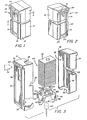
- Fig. 1 is a perspective view of a slide container apparatus in accordance with a first embodiment of the present invention;
- Fig. 2 is a perspective view of the apparatus of Fig. 1 taken from another angle;
- Fig. 3 is an exploded view of the apparatus of Fig. 1 showing a slide stack and a stack positioning element;
- Fig. 4 is a cross-sectional view taken along line 4-4 in Fig. 1 and including a schematic illustration of a nest for the container;
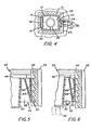
- Fig. 5 is a cross sectional view of the stack positioning element of Fig. 3 and a portion of the container;
- Fig. 6 is a view similar to Fig. 5 showing the configuration of the stack positioning element when pressure is applied to it by a plunger;
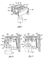
- Fig. 7 is a view, generally similar to that of a portion of Fig. 3, of a second form of stack positioning element in accordance with the present invention;
- Fig. 8 is similar to Fig. 5, but shows the second stack positioning element of Fig. 7; and
- Fig. 9 is similar to Fig. 6, but shows the second stack positioning element of Fig. 7.
- A first embodiment of the present invention, illustrated in Figs. 1 and 2, includes a
container 10 adapted to hold a stack of test slides for supply singly in succession to a chemical analyzer (not shown) such as the analyzer disclosed in French Specification No. 2,374,631.Container 10 includes a generally rectangular casing formed from twoparts chamber 13 for the stack. -
Casing part 12 has a pair ofrails casing part 14 has a similar, but more closely spaced, pair ofrails - To aid in identification of the chemical reagent contained in the slides in the container and to ensure that slides with only a desired chemical reagent are put in a particular nest in the analyzer, each container is provided with a notch code system. Referring to Figs. 2 and 4, a
web 26 extends betweenrails web 26 has been removed, such as by punching, to provide anotch 28. The position of thenotch 28 along the web is predetermined in accordance with particular chemical reagent carried by the slides in the container. Mating structure in theanalyzer nest 24 is provided to interfere with webs other than those notch coded for the proper reagent for the biological test to be performed. In Fig. 4, such mating structure has been schematically shown as apin 29 selectively receivable in a plurality ofholes 33. Eachhole 33 corresponds to a particular biological test so that insertion ofpin 29 into a selectedhole 33 permits reception in the nest of only those containers havingnotches 28 inweb 26 aligned with theselected hole 33. - A
dispensing station 15 at the forward end of thechamber 13 in the container 10 (i.e., at the top of thecontainer 10 as shown in Figs. 1-3) includes a pair ofslots slides 38 from thecontainer 10.Slot 30 is ramped (threeramps 34 are shown) to guide a push blade 36 (Fig. 3) of the analyzer into contact with the trailing edge of the forwardmost slide 38 (i.e., the uppermost in the Figures) of aslide stack 40.Slot 32 has a pair oftabs 41 which normally retain theslides 38 in thecontainer 10 until the forwardmost is pushed out bypush blade 36. Thepush blade 36 extends throughslot 30 to push theforwardmost slide 38 out ofslot 32 and into automatic slide handling means, not shown, of the analyzing apparatus. - When
push blade 36 is withdrawn fromslot 30,slide stack 40 is indexed forwardly (upwardly in the drawings) by a spring-loadedplunger 42 so that the nowforwardmost slide 38 contacts the end of thecontainer 10. Theplunger 42 extends from the analyzing apparatus through an opening 44 in the rear (or bottom) wall of thecontainer 10 to push against astack positioning element 45. Thestack positioning element 45, best seen in perspective in Fig. 3, may be regarded as a box with substantially open top and bottom. Tworails stack 40 ofslides 38.End walls side walls positioning element 45 only in their upper regions indicated by thereference numeral 63. Thus, the lower portions of theend walls positioning element 45. Ratchetpawls end walls ratchet pawls ratchet teeth 56 to inhibit movement of theslides 38 away from the dispensing station ofcontainer 10 should thecontainer 10 be removed from the analyzer nest after some but not all of theslides 38 have been dispensed therefrom. Upon removal of thecontainer 10,plunger 42 is withdrawn from opening 44 so that only cooperation of theratchet pawls ratchet teeth 56 keep theslide stack 40 from becoming disoriented. - The
end walls positioning element 45 are integral with the remainder of the stack-positioning element 45 and are flexible and resilient. Theend walls ratchet pawls ratchet teeth 56 with sufficient force to maintain such engagement when subjected to a reasonably expected amount of jarring. Theend walls ratchet pawls - However, any lateral forces applied to the
ratchet pawls end walls plunger 42 to move thestack positioning element 45 forwardly in thecontainer 10. This resistance can, of course, be offset by a similar increase in the force applied by the plunger, but that increase in force would increase the force to be overcome by an operator loading full containers into the analyzer apparatus. Perhaps the most serious effect of increasing the plunger force would be the increased resistance encountered by thepush blade 36 when it is activated to push the forwardmost slide from thestack 40. Therefore, it is desirable to keep the springforce urging plunger 42 forwardly to a minimum. Accordingly, the present invention provides means for decreasing the lateral force applied to theratchet pawls plunger 42 pushes against thestack positioning element 45, while permitting the maximum lateral force to be applied when thecontainer 10 is not received in thenest 24 of the analyzing apparatus. - Referring to Fig. 5, a partial cross-sectional view of
stack positioning element 45 and one of the container walls, which form the boundary of the chamber, shows the cooperation betweenratchet pawl 52 andratchet teeth 56 when thecontainer 10 is removed from the analyzer apparatus. Ratchetpawl 52 is urged byflexible end wall 60 into the space between theratchet teeth 56 to prevent downward movement of thestack positioning element 45. The lateral force ofend wall 60 pushingratchet pawl 52 into engagement with theratchet teeth 56 is sufficient to prevent theratchet pawl 52 from being jarred from theratchet teeth 56 during handling. - A hollow cup-shaped member 62 (for storing desiccant) forms a part of
stack positioning element 45 and is attached toflexible end walls webs 64 and 66 (See Fig. 3) extending from the top of the cup-shaped member 62 to the lower ends ofend walls container 10 is inserted into anest 24 so that theplunger 42 enters thecontainer 10 through its bottom opening 44, theplunger 42 resiliently pushes against the bottom of cup-shaped member 62. Sincerails slide stack 40, the main body of thestack positioning element 45 cannot move upwardly in thecontainer 10 until aslide 38 has been dispensed. However, cup-shaped member 62, which is attached to the main body of thestack positioning element 45 byend walls webs dispensing station 15 relative to thestack positioning element 45 through flexing ofend walls shaped member 62 and thewebs end walls ratchet pawls - The result of this movement (somewhat exaggerated for clarity) is shown in Fig. 6. Note that
plunger 42 has pushed cup-shaped member 62 upwardly relative torail 46.End wall 60 has flexed and ratchet'pawl 52 has moved somewhat out of the space betweenratchet teeth 56. Now, asslides 38 are removed successively from thecontainer 10,ratchet pawls stack positioning element 45. Therefore, the spring pressure exerted byplunger 42 may be less than would be required if the lateral force onratchet pawls - When the
container 10 is removed from the analyzing apparatus, cup-shaped member 62 once again returns to its Fig. 5 position relative torails ratchet pawls ratchet teeth 56 and the possibility of theratchet pawls ratchet teeth 56 is decreased. It should be noted it is not necessary for ratchet pawls 50 and 52 to move entirely out of the spaces between ratchetteeth 56 to reduce the resistance to upward movement ofstack positioning element 45 when force is applied to thestack positioning element 45 to move it toward the dispensingstation 15 ofcontainer 10. - Portions of a second embodiment of the present invention are illustrated in Figs. 7 to 9. In this second embodiment parts and features which are structurally and/or functionally similar to parts and features in the first embodiment are given the same reference numerals but with a prime (') suffix. Those parts and features which are the same in the second embodiment as in the first embodiment will not be described again and for a full understanding of portions of the second embodiment not described, reference should be made to the description and illustrations of the first embodiment.
- The stack positioning element 45' of the second embodiment is generally similar to that of the first embodiment but lacks the cup-shaped
member 62 and thewebs perpendicular flange flanges flanges flanges integral bridge 80 which is of dished form, rather than rectilinear. - The lower edges 76 of the
flanges inner corners 78 of theflanges - Figs. 7 and 8 represent the condition of the stack positioning element 45' when the plunger 42' is not engaging it. In this condition the ratchet pawls 50', 52' are biased outwards into spaces between ratchet teeth 56' and resist downwards (as seen in the Figures) movement of the stack positioning element 45' and slide stack 40' within the
chamber 13'. Thus the slides are kept in close, stacked form and are prevented from assuming random orientation and, perhaps, overturning. - In Fig. 9 the plunger 42' is in forced engagement with the
corners 78 of theflanges - The relaxed condition of the element 45' is that illustrated in Figs. 7 and 8. In the Fig. 9 condition stresses are created at the regions 63' of connection of the end walls 58', 60' with the side walls 59', 61' which stresses tend to return the element to the Figs. 7 and 8 condition when the plunger 42' is disengaged from the
flanges - As can be seen in Fig. 9, the ratchet pawls 50', 52' will not contact the ratchet teeth 56' when the element 45' moves forwardly (upwardly as seen in the Figs.), whereas in the first described embodiment there may be some chattering as the ratchet pawls move over the ratchet teeth. Thus the second embodiment has the benefit that the spring force urging the plunger may be yet further reduced.
- In this second embodiment because the ratchet pawls 50', 52' are displaced inwards by such distances that they do not contact the ratchet teeth 56' upon forwards movement, it follows that the ratchet pawls might not engage the ratchet teeth upon rearwards (downwards as seen in the Figs.) movement of the stack positioning element 45' unless the following is observed. The ratchet pawls 50', 52' should be displaced to a position in which they always still extend into the sets of ratchet teeth by some at least minimal extent when relative movement of the plunger 42' out of the container has just commenced. This desideratum is achieved if the stack positioning element 45' is so constructed that the condition exists with a full slide stack 40' but in the absence of any reaction force by the end wall of the container on the forwardmost slide. Upon commencement of relative withdrawal of the plunger 42' the forwardmost slide will move out of contact with the end wall of the container. Hence the reaction force of the end wall on the forwardmost slide is lost. Therefore, the stress in the element is reduced and the end walls 58' 60' move out. Once the ratchet pawls 50', 52' have at least just caught on the ratchet teeth 56' rearwards motion of the stack 40' is prevented and the rocking motion of the
flanges corners 78 of theflanges - The
bridge 80 serves to ensure that theflanges
Claims (6)
Applications Claiming Priority (2)
| Application Number | Priority Date | Filing Date | Title |
|---|---|---|---|
| US912290 | 1978-06-05 | ||
| US05/912,290 US4151931A (en) | 1978-06-05 | 1978-06-05 | Article dispenser apparatus for use in an automated chemical analyzer |
Publications (2)
| Publication Number | Publication Date |
|---|---|
| EP0007173A1 EP0007173A1 (en) | 1980-01-23 |
| EP0007173B1 true EP0007173B1 (en) | 1982-03-17 |
Family
ID=25431668
Family Applications (1)
| Application Number | Title | Priority Date | Filing Date |
|---|---|---|---|
| EP79301060A Expired EP0007173B1 (en) | 1978-06-05 | 1979-06-05 | Magazine for articles to be dispensed from a stack |
Country Status (5)
| Country | Link |
|---|---|
| US (1) | US4151931A (en) |
| EP (1) | EP0007173B1 (en) |
| JP (1) | JPS5753271Y2 (en) |
| CA (1) | CA1103625A (en) |
| DE (1) | DE2962279D1 (en) |
Families Citing this family (33)
| Publication number | Priority date | Publication date | Assignee | Title |
|---|---|---|---|---|
| US4279861A (en) * | 1979-05-09 | 1981-07-21 | Eastman Kodak Company | Cartridge discriminator for an automated analysis system |
| JPS6038660B2 (en) * | 1979-05-11 | 1985-09-02 | オリンパス光学工業株式会社 | Sample supply device |
| US4303611A (en) * | 1980-08-11 | 1981-12-01 | Eastman Kodak Company | Analyzer apparatus featuring a simplified incubator |
| US4440301A (en) * | 1981-07-16 | 1984-04-03 | American Hospital Supply Corporation | Self-stacking reagent slide |
| CA1205302A (en) * | 1984-01-09 | 1986-06-03 | Wing C. Fong | Gas sampling device |
| US4613421A (en) * | 1984-01-25 | 1986-09-23 | Fuji Photo Film Co., Ltd. | Apparatus for measuring ionic activity |
| US4718590A (en) * | 1986-07-28 | 1988-01-12 | Bernard Engelhardt | Fastener dispensing devices |
| US4706846A (en) * | 1986-07-28 | 1987-11-17 | Bernard Engelhardt | Tag dispenser |
| JP2543243B2 (en) * | 1990-09-05 | 1996-10-16 | 株式会社京都第一科学 | Automatic sample analyzer |
| DE69331861T2 (en) * | 1992-01-16 | 2002-08-29 | Fuji Photo Film Co Ltd | Chemical analysis system |
| JP2903273B2 (en) * | 1992-04-20 | 1999-06-07 | 富士写真フイルム株式会社 | Method for transporting dry analytical film pieces and cartridge |
| US5332549A (en) * | 1992-07-01 | 1994-07-26 | Pb Diagnostic Systems, Inc. | Assay module transport apparatus for use in an automated analytical instrument |
| US5534224A (en) * | 1993-07-16 | 1996-07-09 | Fuji Photo Film Co., Ltd. | Chemical analysis film cartridge |
| US5536472A (en) * | 1993-11-22 | 1996-07-16 | Fuji Photo Film Co., Ltd. | Chemical analysis element cartridge |
| JP3328061B2 (en) * | 1994-04-15 | 2002-09-24 | 富士写真フイルム株式会社 | Cartridge for dry analysis film |
| US5856194A (en) | 1996-09-19 | 1999-01-05 | Abbott Laboratories | Method for determination of item of interest in a sample |
| US5795784A (en) | 1996-09-19 | 1998-08-18 | Abbott Laboratories | Method of performing a process for determining an item of interest in a sample |
| DE19746455C1 (en) * | 1997-10-21 | 1999-05-27 | Jenoptik Jena Gmbh | Automatic pipetting and handling device for microtitration plates with permeable bottoms |
| US6098839A (en) * | 1998-05-07 | 2000-08-08 | Triangle Biomedical Sciences, Inc. | Article dispensing assembly |
| US6238354B1 (en) | 1999-07-23 | 2001-05-29 | Martin A. Alvarez | Temperature monitoring assembly |
| US6230931B1 (en) * | 1999-07-30 | 2001-05-15 | Warner-Lambert Company | Dispensing package |
| JP2001318103A (en) * | 2000-05-11 | 2001-11-16 | Fuji Photo Film Co Ltd | Feeder for dry analytical element |
| US20040134928A1 (en) * | 2003-01-09 | 2004-07-15 | Wagner Nancy Ann | Methods and apparatus for storing and dispensing coasters |
| US7632468B2 (en) * | 2003-12-04 | 2009-12-15 | Idexx Laboratories, Inc. | Retaining clip for reagent test slides |
| US7588733B2 (en) * | 2003-12-04 | 2009-09-15 | Idexx Laboratories, Inc. | Retaining clip for reagent test slides |
| GB2429525A (en) * | 2005-03-11 | 2007-02-28 | Colman Group Inc | Test strip dispenser and thermometer holder |
| EP2130041A1 (en) * | 2007-03-12 | 2009-12-09 | Bayer Healthcare, LLC | Single-sensor meter system with no sensor handling and method of using the same |
| US20110204080A1 (en) * | 2007-11-29 | 2011-08-25 | Nu-Life Products, Inc. | Single Stack Wafer Dispenser |
| WO2009102764A2 (en) * | 2008-02-11 | 2009-08-20 | Nu-Life Products, Inc. | Wafer dispenser |
| DE102008059673A1 (en) * | 2008-11-26 | 2010-05-27 | Bayer Schering Pharma Aktiengesellschaft | Cartridge, a drug dispenser containing the cartridge and uses of the cartridge and the drug dispenser |
| MX2016005945A (en) | 2013-11-07 | 2017-09-28 | Accutec Blades Inc | Blade dispenser. |
| USD832116S1 (en) | 2014-05-22 | 2018-10-30 | Accutec Blades, Inc | Blade dispenser |
| US10259642B2 (en) | 2015-12-17 | 2019-04-16 | Accutec Blades, Inc. | Blade dispenser |
Family Cites Families (7)
| Publication number | Priority date | Publication date | Assignee | Title |
|---|---|---|---|---|
| US1801165A (en) * | 1929-05-13 | 1931-04-14 | Gordon B Macke | Vending machine |
| US3115991A (en) * | 1958-03-03 | 1963-12-31 | American Can Co | Cutting blade magazine and dispenser |
| GB1095429A (en) * | 1965-05-17 | |||
| GB1198488A (en) * | 1966-08-23 | 1970-07-15 | Hans Peter Olof Unger | Improvements in or relating to Automated Analysis |
| GB1295262A (en) * | 1969-01-28 | 1972-11-08 | ||
| JPS4728175U (en) * | 1971-04-16 | 1972-11-30 | ||
| JPS4923351U (en) * | 1972-05-29 | 1974-02-27 |
-
1978
- 1978-06-05 US US05/912,290 patent/US4151931A/en not_active Expired - Lifetime
- 1978-10-27 CA CA314,635A patent/CA1103625A/en not_active Expired
-
1979
- 1979-06-05 JP JP1979076473U patent/JPS5753271Y2/ja not_active Expired
- 1979-06-05 DE DE7979301060T patent/DE2962279D1/en not_active Expired
- 1979-06-05 EP EP79301060A patent/EP0007173B1/en not_active Expired
Also Published As
| Publication number | Publication date |
|---|---|
| DE2962279D1 (en) | 1982-04-15 |
| EP0007173A1 (en) | 1980-01-23 |
| JPS5753271Y2 (en) | 1982-11-18 |
| CA1103625A (en) | 1981-06-23 |
| JPS54180030U (en) | 1979-12-19 |
| US4151931A (en) | 1979-05-01 |
Similar Documents
| Publication | Publication Date | Title |
|---|---|---|
| EP0007173B1 (en) | Magazine for articles to be dispensed from a stack | |
| US4187077A (en) | Container with article positioning element for dispensing reagent coated slides to an automated analyzer | |
| KR100515174B1 (en) | Connecting device for card pushing the card by slider | |
| JP4221901B2 (en) | Assembly containing stacked pipette cone refills | |
| US3941244A (en) | Magazine for razor blade cartridges | |
| EP0589443B1 (en) | Magnetic tape cartridge having leader block retainer mechanism | |
| US4266840A (en) | Circuit holder | |
| US20040077226A1 (en) | Small form-factor transceiver module with pull-to-release | |
| US4580192A (en) | Latching and withdrawing assembly for plug-in circuit packs | |
| US20030054694A1 (en) | Connector for memory card | |
| US3994550A (en) | Holders for tape cassettes | |
| KR20010107023A (en) | Memory connector | |
| US6503093B1 (en) | Circuit board electrical connector | |
| JPH04296477A (en) | Card edge connector | |
| US4846355A (en) | Holder for tape cartridges with locking base member | |
| US4415079A (en) | Holder for photographic prints | |
| US7198498B2 (en) | Card connector | |
| EP1791224A1 (en) | Card edge connector | |
| EP1281177A2 (en) | Universal media module | |
| JPH07311201A (en) | Cartridge for dry-type analysis slide | |
| US3070260A (en) | Dispensing magazine for razor blades | |
| EP1027704A1 (en) | Receiver and magazine assembly for storage library system | |
| JPH01259806A (en) | Stackable drawer box | |
| US4806118A (en) | Fuse package | |
| KR0137208B1 (en) | Container for receiving a cassette with a tape like recording media |
Legal Events
| Date | Code | Title | Description |
|---|---|---|---|
| PUAI | Public reference made under article 153(3) epc to a published international application that has entered the european phase |
Free format text: ORIGINAL CODE: 0009012 |
|
| AK | Designated contracting states |
Designated state(s): BE CH DE FR GB IT SE |
|
| DET | De: translation of patent claims | ||
| 17P | Request for examination filed | ||
| ITF | It: translation for a ep patent filed |
Owner name: MODIANO & ASSOCIATI S.R.L. |
|
| GRAA | (expected) grant |
Free format text: ORIGINAL CODE: 0009210 |
|
| AK | Designated contracting states |
Designated state(s): BE CH DE FR GB IT SE |
|
| REF | Corresponds to: |
Ref document number: 2962279 Country of ref document: DE Date of ref document: 19820415 |
|
| PGFP | Annual fee paid to national office [announced via postgrant information from national office to epo] |
Ref country code: CH Payment date: 19910611 Year of fee payment: 13 |
|
| PGFP | Annual fee paid to national office [announced via postgrant information from national office to epo] |
Ref country code: SE Payment date: 19910614 Year of fee payment: 13 |
|
| ITTA | It: last paid annual fee | ||
| PGFP | Annual fee paid to national office [announced via postgrant information from national office to epo] |
Ref country code: BE Payment date: 19910715 Year of fee payment: 13 |
|
| PG25 | Lapsed in a contracting state [announced via postgrant information from national office to epo] |
Ref country code: SE Effective date: 19920606 |
|
| PG25 | Lapsed in a contracting state [announced via postgrant information from national office to epo] |
Ref country code: CH Effective date: 19920630 Ref country code: BE Effective date: 19920630 |
|
| BERE | Be: lapsed |
Owner name: EASTMAN KODAK CY Effective date: 19920630 |
|
| REG | Reference to a national code |
Ref country code: CH Ref legal event code: PL |
|
| EUG | Se: european patent has lapsed |
Ref document number: 79301060.4 Effective date: 19930109 |
|
| REG | Reference to a national code |
Ref country code: GB Ref legal event code: 732E |
|
| PGFP | Annual fee paid to national office [announced via postgrant information from national office to epo] |
Ref country code: GB Payment date: 19970527 Year of fee payment: 19 |
|
| PGFP | Annual fee paid to national office [announced via postgrant information from national office to epo] |
Ref country code: FR Payment date: 19970610 Year of fee payment: 19 |
|
| PGFP | Annual fee paid to national office [announced via postgrant information from national office to epo] |
Ref country code: DE Payment date: 19970613 Year of fee payment: 19 |
|
| PG25 | Lapsed in a contracting state [announced via postgrant information from national office to epo] |
Ref country code: GB Free format text: LAPSE BECAUSE OF NON-PAYMENT OF DUE FEES Effective date: 19980605 |
|
| GBPC | Gb: european patent ceased through non-payment of renewal fee |
Effective date: 19980605 |
|
| PG25 | Lapsed in a contracting state [announced via postgrant information from national office to epo] |
Ref country code: FR Free format text: LAPSE BECAUSE OF NON-PAYMENT OF DUE FEES Effective date: 19990226 |
|
| PG25 | Lapsed in a contracting state [announced via postgrant information from national office to epo] |
Ref country code: DE Free format text: LAPSE BECAUSE OF NON-PAYMENT OF DUE FEES Effective date: 19990401 |
|
| REG | Reference to a national code |
Ref country code: FR Ref legal event code: ST |
|
| PLBE | No opposition filed within time limit |
Free format text: ORIGINAL CODE: 0009261 |
|
| STAA | Information on the status of an ep patent application or granted ep patent |
Free format text: STATUS: NO OPPOSITION FILED WITHIN TIME LIMIT |