EP0010512A1 - Method to carry off gases - Google Patents
Method to carry off gases Download PDFInfo
- Publication number
- EP0010512A1 EP0010512A1 EP79710094A EP79710094A EP0010512A1 EP 0010512 A1 EP0010512 A1 EP 0010512A1 EP 79710094 A EP79710094 A EP 79710094A EP 79710094 A EP79710094 A EP 79710094A EP 0010512 A1 EP0010512 A1 EP 0010512A1
- Authority
- EP
- European Patent Office
- Prior art keywords
- pressure
- gases
- liquid
- closed container
- under
- Prior art date
- Legal status (The legal status is an assumption and is not a legal conclusion. Google has not performed a legal analysis and makes no representation as to the accuracy of the status listed.)
- Granted
Links
- 239000007789 gas Substances 0.000 title claims abstract description 32
- 238000000034 method Methods 0.000 title claims abstract description 17
- 239000013535 sea water Substances 0.000 claims abstract description 12
- 238000010612 desalination reaction Methods 0.000 claims abstract description 4
- 238000007599 discharging Methods 0.000 claims abstract description 4
- XLYOFNOQVPJJNP-UHFFFAOYSA-N water Substances O XLYOFNOQVPJJNP-UHFFFAOYSA-N 0.000 claims description 20
- 230000002706 hydrostatic effect Effects 0.000 claims description 4
- 238000001223 reverse osmosis Methods 0.000 claims description 3
- 239000007788 liquid Substances 0.000 claims 6
- 238000007664 blowing Methods 0.000 description 1
- 125000004122 cyclic group Chemical group 0.000 description 1
- 230000000694 effects Effects 0.000 description 1
- 239000013505 freshwater Substances 0.000 description 1
- 230000000737 periodic effect Effects 0.000 description 1
Images

Classifications
-
- B—PERFORMING OPERATIONS; TRANSPORTING
- B01—PHYSICAL OR CHEMICAL PROCESSES OR APPARATUS IN GENERAL
- B01J—CHEMICAL OR PHYSICAL PROCESSES, e.g. CATALYSIS OR COLLOID CHEMISTRY; THEIR RELEVANT APPARATUS
- B01J3/00—Processes of utilising sub-atmospheric or super-atmospheric pressure to effect chemical or physical change of matter; Apparatus therefor
- B01J3/02—Feed or outlet devices therefor
-
- B—PERFORMING OPERATIONS; TRANSPORTING
- B01—PHYSICAL OR CHEMICAL PROCESSES OR APPARATUS IN GENERAL
- B01D—SEPARATION
- B01D19/00—Degasification of liquids
-
- B—PERFORMING OPERATIONS; TRANSPORTING
- B01—PHYSICAL OR CHEMICAL PROCESSES OR APPARATUS IN GENERAL
- B01D—SEPARATION
- B01D61/00—Processes of separation using semi-permeable membranes, e.g. dialysis, osmosis or ultrafiltration; Apparatus, accessories or auxiliary operations specially adapted therefor
- B01D61/02—Reverse osmosis; Hyperfiltration ; Nanofiltration
- B01D61/10—Accessories; Auxiliary operations
-
- B—PERFORMING OPERATIONS; TRANSPORTING
- B01—PHYSICAL OR CHEMICAL PROCESSES OR APPARATUS IN GENERAL
- B01D—SEPARATION
- B01D2313/00—Details relating to membrane modules or apparatus
- B01D2313/24—Specific pressurizing or depressurizing means
-
- Y—GENERAL TAGGING OF NEW TECHNOLOGICAL DEVELOPMENTS; GENERAL TAGGING OF CROSS-SECTIONAL TECHNOLOGIES SPANNING OVER SEVERAL SECTIONS OF THE IPC; TECHNICAL SUBJECTS COVERED BY FORMER USPC CROSS-REFERENCE ART COLLECTIONS [XRACs] AND DIGESTS
- Y02—TECHNOLOGIES OR APPLICATIONS FOR MITIGATION OR ADAPTATION AGAINST CLIMATE CHANGE
- Y02A—TECHNOLOGIES FOR ADAPTATION TO CLIMATE CHANGE
- Y02A20/00—Water conservation; Efficient water supply; Efficient water use
- Y02A20/124—Water desalination
- Y02A20/131—Reverse-osmosis
-
- Y—GENERAL TAGGING OF NEW TECHNOLOGICAL DEVELOPMENTS; GENERAL TAGGING OF CROSS-SECTIONAL TECHNOLOGIES SPANNING OVER SEVERAL SECTIONS OF THE IPC; TECHNICAL SUBJECTS COVERED BY FORMER USPC CROSS-REFERENCE ART COLLECTIONS [XRACs] AND DIGESTS
- Y10—TECHNICAL SUBJECTS COVERED BY FORMER USPC
- Y10T—TECHNICAL SUBJECTS COVERED BY FORMER US CLASSIFICATION
- Y10T137/00—Fluid handling
- Y10T137/8593—Systems
- Y10T137/86187—Plural tanks or compartments connected for serial flow
- Y10T137/86196—Separable with valved-connecting passage
Definitions
- the invention relates to a method for discharging gases from a closed container into a medium located outside of this and under a higher pressure.
- the invention relates to a method for discharging gases from submarine desalination plants into the surrounding sea water.
- a vent line is expensive because it is subject to high hydrostatic external pressure at sea depth and is exposed to the effects of the sea near the surface of the sea.
- a compressor located at sea level would be expensive and difficult to maintain because of the large operational pressure differences and the necessary energy supply.
- the object is achieved in that the gases transferred from the pressure vessel into a separate pressure-resistant container through the product water line and under high pressure product water are brought to a pressure exceeding the hydrostatic ambient pressure and then are expelled into the surrounding sea water and finally that in product water located in the separate container is drained into the pressure vessel.
- the pressure-resistant container is connected to the pressure vessel, the product water line and the surrounding sea water via lockable pressure-resistant lines.
- the shut-off devices are coupled to one another by appropriate measures so that they can only open and close in a cyclical order according to the program.
- 1 denotes the pressure vessel in which the gases collect
- 2 the pressure-resistant container, which is connected via line 4 and.
- the valve 5 with 1 via the line 6 and the valve 7 can be connected to the product water line 3 and via the line 8 and the valve 9 to the surrounding sea water.
- lines 6 and 8 are only in one Direction flow, they can also be provided with check valves (not shown here) to prevent possible leakage of sea water via 2 in 3. Appropriate measures ensure that none of the valves can be opened without a program.
- the lines 4 and the valve 5 can be present twice, the one intended for gas transport Line 4 begins in the vicinity of the highest point of 1 and continues in 2 in a riser pipe reaching to its highest point, while the line 10 intended for water transport begins in the bottom of FIG. 2 and continues in FIG. 1 in a downpipe 13 that extends a little, possibly up to the vicinity of the bottom of FIG.
- This arrangement has the additional advantage that the gases from 1 in 2 are sucked in by the height difference of the water levels in 2 and 1.
- the two lines 4 and 10 can be provided with check valves (not shown here) in addition to the valves 5 and 11 that open and close simultaneously.
- the cyclical opening and closing of the lines 4 6 and 8 takes place automatically due to the gas pressure building up in FIG. 1 and the function of the periodic changes caused by the arrangement at the ends of each the lines 4, 6 and 8 occurring pressure differences.
- the valves 5, 7 and 9 shown in FIG. 2 take the place of check valves which only open at certain overpressures and are interlocked with one another by means of suitable measures so that they cannot open according to the program.
- the ambient pressure being p o
- the pressures prevailing in the pressure vessel 1 and the container 2 being p 1 and p 2
- the pressure in the product water line being p 3 .
- the clear width of line 6 is considerably smaller than that of line 8.
- the seepage line 10, which is provided with a check valve 11 and via which and 2 are connected to one another, has such a high flow resistance that even with large ones Pressure difference can pass only minimal amounts of water.
Abstract
Die Erfindung betrifft ein Verfahren zur Abführung von Gasen aus einem geschlossenen Behälter (1) in ein außerhalb von diesem befindliches unter einem höheren Druck stehendes Medium. Hierbei werden die Gase auf einen den Druck des Mediums übertreffenden Druck gebracht, bevor sie in dieses abgeführt werden. Die Erfindung ist besonders für das Abführen von Gasen aus submarinen Entsalzungsanlagen in das umgebende Meerwasser geeignet.The invention relates to a method for discharging gases from a closed container (1) into a medium located outside of it and under a higher pressure. Here, the gases are brought to a pressure exceeding the pressure of the medium before they are discharged into it. The invention is particularly suitable for the discharge of gases from submarine desalination plants into the surrounding sea water.
Description
Die Erfindung betrifft ein Verfahren zur Abführung von Gasen aus einem geschlossenen Behälter in ein außerhalb von diesem befindliches unter einem höheren Druck stehendes Medium.
Insbesondere betrifft die Erfindung ein Verfahren zur Abführung von Gasen aus submarinen Entsalzungsanlagen in das umgebende Meerwasser.The invention relates to a method for discharging gases from a closed container into a medium located outside of this and under a higher pressure.
In particular, the invention relates to a method for discharging gases from submarine desalination plants into the surrounding sea water.
Im Meerwasser gelöste Gase, die sich unter Umständen in dem Druckgefäß einer nach dem Prinzip der Umgekehrten Osmose ; arbeitenden submarinen Entsalzungsanlage ansammeln, können deren Funktion dadurch beeinträchtigen, daß sie den transmembranen Druckunterschied erheblich verringern und bei gewissen unzulässigen Betriebszuständen, z.B. starkem Schwanken des Druckgefäßes, stoßweise zu einer 2-Phasenströmung führen. Sie müssen in größeren oder kleineren Zeitabständen aus dem Druckgefäß entfernt werden. Wegen der Anordnung solcher Anlagen in der Meerestiefe muß das in möglichst einfacher und zuverlässiger Weise geschehen.Gases dissolved in seawater, which may be in the pressure vessel of a reverse osmosis principle; working submarine desalination plant can impair their function in that they significantly reduce the transmembrane pressure difference and in certain impermissible operating states, e.g. strong fluctuation of the pressure vessel, intermittently lead to a 2-phase flow. They have to be removed from the pressure vessel at larger or smaller intervals. Because of the arrangement of such systems at sea depth, this must be done in the simplest and most reliable way possible.
Das einfachste Mittel, eine Erhöhung des Innendruckes des Druckgefäßes durch permeierende Gase zu verhindern, ist eine bis an die Meeresoberfläche reichende Entlüftungsleitung (vgl. Peters, Th., E. Klapp und B.C. Drude: Feasibility Study on Submarine Units for Reverse Osmosis. Proc. 5th Int. Symp. on Fresh Water from the Sea 4 (1976), S. 365/75). Ein anderes naheliegendes, wenn auch nicht in diesem Zusammenhang genanntes Verfahren wäre dies, die Gase in einen getrennten Behälter zu überführen, dort maschinell auf den erforderlichen Druck zu bringen und dann in das Meerwasser austreten zu lasSen.The simplest means of preventing an increase in the internal pressure of the pressure vessel by permeating gases is a vent line reaching to the surface of the sea (see Peters, Th., E. Klapp and BC Drude: Feasibility Study on Submarine Units for Reverse Osmosis. Proc. 5th Int. Symp. On Fresh Water from the Sea 4 (1976), pp. 365/75). Another obvious method, although not mentioned in this context, would be to transfer the gases into a separate container, to bring them to the required pressure by machine, and then to let them escape into the sea water.
Keine dieser Alternativen stellt eine befriedigende Lösung des Problems dar. Eine Entlüftungsleitung ist teuer, da sie in der Meerestiefe dem hohen hydrostatischen Außendruck unterliegt und in der Nähe der Meeresoberfläche den Einwirkungen des Seeganges ausgesetzt ist. Andererseits wäre ein in der Meerestiefe angeordneter Kompressor wegen der großen betriebsmäßig auftretenden Druckunterschiede und der nötigen Energieversorgung kostspielig und schwer zu warten.Neither of these alternatives is a satisfactory solution to the problem. A vent line is expensive because it is subject to high hydrostatic external pressure at sea depth and is exposed to the effects of the sea near the surface of the sea. On the other hand, a compressor located at sea level would be expensive and difficult to maintain because of the large operational pressure differences and the necessary energy supply.
Damit ergibt sich die Aufgabe, ein einfaches, billigeres und zuverlässiges Verfahren für die Beseitigung der Gase zu finden.
Die Aufgabe wird erfindungsgemäß dadurch gelöst, daß die aus dem Druckgefäß in einen getrennten druckfesten Behälter überführten Gase durch der Produktwasserleitung entnommenes und unter hohem Druck stehendes Produktwasser auf einen den hydrostatischen Umgebungsdruck übersteigenden Druck gebracht und dann in das umgebende Meerwasser ausgestoßen werden und daß schließlich das in dem getrennten Behälter befindliche Produktwasser in das Druckgefäß abgelassen wird.This gives rise to the task of finding a simple, cheaper and reliable method for removing the gases.
The object is achieved in that the gases transferred from the pressure vessel into a separate pressure-resistant container through the product water line and under high pressure product water are brought to a pressure exceeding the hydrostatic ambient pressure and then are expelled into the surrounding sea water and finally that in product water located in the separate container is drained into the pressure vessel.
Zur Durchführung dieses Verfahrensablaufes steht der druckfeste Behälter mit dem Druckgefäß, der Produktwasserleitung und dem umgebenden Meerwasser über absperrbare druckfeste Leitungen in Verbindung. Die Absperrorgane sind durch entsprechende Maßnahmen so miteinander verkuppelt, daß sie nur programmgemäß in zyklischer Reihenfolge öffnen und schließen können.To carry out this process sequence, the pressure-resistant container is connected to the pressure vessel, the product water line and the surrounding sea water via lockable pressure-resistant lines. The shut-off devices are coupled to one another by appropriate measures so that they can only open and close in a cyclical order according to the program.
Diese Lösung der Aufgabe zeichnet sich vor allem durch folgende Vorteile aus:
- E3 ist keine zusätzliche maschinelle Vorrichtung erfordrlich;
- - daher wird auch keine besondere Energie-Versorgungseinrichtung benötigt;
- - ungünstige Bedingungen auf der Saugseite der Pumpe werden vermieden;
- - abgesehen von den Absperrerganen erfordert das Verfahren keine Bewegung zusätzlicher Anlageteile;
- - bei den im Verhältnis zur Produktwassermenge geringen Gasmengen können gewisse Undichtigkeiten der Absperrorgane zugelassen werden;
- - die zyklische Öffnung und Schließung der Absperrorgane kann durch Eingriff von außen oder auch selbsttätig erfolgen;
- - die Kosten sind verhältnismäßig niedrig.
- E3 no additional mechanical device is required;
- - Therefore, no special energy supply device is required;
- - unfavorable conditions on the suction side of the pump are avoided;
- - Apart from the shut-off gans, the process does not require the movement of additional system parts;
- - With the small amounts of gas in relation to the amount of product water, certain leaks in the shut-off devices can be permitted
- - The cyclic opening and closing of the shut-off devices can be done by external intervention or automatically;
- - The costs are relatively low.
Die Erfindung soll an Hand von Ausführungsbeispielen nachfolgend erläutert werden.The invention will be explained below using exemplary embodiments.
Dabei zeigt:
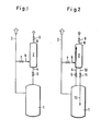
- Figur 1 eine schematische Darstellung der Anordnung zur Durchführung des erfindungsgemäßen Verfahrens,
Figur 2 eine abgewandelte Ausführung undFigur 3 ein weiteres Ausführungsbeispiel.
- FIG. 1 shows a schematic representation of the arrangement for carrying out the method according to the invention,
- Figure 2 shows a modified version and
- Figure 3 shows another embodiment.
In der Figur 1 bezeichnet 1 das Druckgefäß, in dem sich die Gase ansammeln, und 2 den druckfesten Behälter, der über die Leitung 4 und. das Ventil 5 mit 1, über die Leitung 6 und das Ventil 7 mit der Produktwasserleitung 3 und über die Leitung 8 und das Ventil 9 mit dem umgebenden Meerwasser verbunden werden kann. Da die Leitungen 6 und 8 nur in einer Richtung durchströmt werden, können sie zur Verhinderung eines eventuellen Durchsickerns von Meerwasser über 2 in 3 noch zusätzlich mit (hier nicht gezeichneten) Rückschlagventilen versehen sein. Durch entsprechende Maßnahmen wird sichergestellt, daß keines der Ventile unprogrammgemäß geöffnet werden kann.In FIG. 1, 1 denotes the pressure vessel in which the gases collect, and 2 the pressure-resistant container, which is connected via line 4 and. the valve 5 with 1, via the
Funktionsablauf der Vorrichtung ist wie folgt:
- 1) 2 öffnet: durch 4 tritt eine Gasmenge aus 1 in 2, während gleichzeitig in 2 befindliches Produktwasser aus 2 in 1 fließt. 5 schließt.
- 2) 7 öffnet: aus 3 tritt das hier unter hohem Druck stehende Produktwasser über 6 in 2 ein und komprimiert die dort eingeschlossene Gasmenge.
- 3) 9 öffnet: die komprimierte Gasmenge tritt über 8 in das umgebende Meerwasser-ein. 7 und 9 schließen gleichzeitig. Diese Schritte wiederholen sich in geeigneten Zeitabständen in zyklischer Reihenfolge.
- 1) 2 opens: through 4 a gas quantity emerges from 1 in 2, while at the same time product water in 2 flows from 2 in 1. 5 closes.
- 2) 7 opens: from 3 the product water, which is under high pressure, enters via 6 in 2 and compresses the amount of gas enclosed there.
- 3) 9 opens: the compressed gas volume enters the surrounding sea water via 8. 7 and 9 close at the same time. These steps are repeated at suitable intervals in a cyclical order.
Dadurch,daß der Leitung 6 und dem Ventil 7 eine wesentlich kleinere lichte Weite gegeben wird als der Leitung 8 und dem Ventil 9, wird erreicht, daß nach Abblasen der Gase aus 2 weiteres Produktwasser aus 3 nur langsam ra chströmt, so daß nicht viel Produktwasser verlorengeht.The fact that the
Um sicherzustellen, daß bei geöffnetem Ventil 5 der Übertritt des Produktwassers aus 2 in 1 und die gleichzeitig gegenläufige Bewegung von Gasen von 1 nach 2 sich nicht gegenseitig behindern, können die Leitungen 4 und das Ventil 5 doppelt vorhanden sein, wobei die für den Gastransport bestimmte Leitung 4 in der Nähe der höchsten Stelle von 1 beginnt und sich in 2 in einem bis dicht an dessen höchste Stelle reichendem Steigrohr fortsetzt, während die für den Wassertransport bestimmte Leitung 10 im Boden von 2 beginnt und sich in 1 in einem Fallrohr 13 fortsetzt, das ein Stück, eventuell bis in die Nähe des Bodens von 1 reicht. Diese Anordnung hat den zusätzlichen Vorteil, daß durch die Höhendifferenz der Wasserspiegel in 2 und 1 die Gase aus 1 in 2 gesaugt werden. Bei dieser in Figur 2 gezeigten Anordnung können die beiden Leitungen 4 und 10 außer mit den gleichzeitig öffnenden und schließenden Ventilen 5 und 11 auch mit (hier nicht gezeichneten) Rückschlagventilen versehen sein.In order to ensure that when the valve 5 is open, the passage of the product water from 2 into 1 and the simultaneously opposite movement of gases from 1 to 2 do not interfere with one another, the lines 4 and the valve 5 can be present twice, the one intended for gas transport Line 4 begins in the vicinity of the highest point of 1 and continues in 2 in a riser pipe reaching to its highest point, while the
Bei wieder einer anderen, auf demselben erfindungsgemäßer Verfahren zur Ausstoßung von Gasen beruhenden Anordnung erfolgt die zyklische Öffnung und Schließung der Leitungen 4 6 und 8 selbsttätig durch den sich in 1 aufbauenden Gasdruck und die Funktion der durch die Anordnung bedingten periodischen Änderungen der an den Enden jeder der Leitungen 4, 6 und 8 auftretenden Druckunterschiede. Bei dieser Anordnung treten an die Stelle der in Figur 2 gezeigten Ventile 5, 7 und 9 Rückschlagventile, die nur bei gewissen Überdrücken öffnen und mittels geeigneter Maßnahmen so mit einander verriegelt sind, daß sie nicht umprogrammmäßig öffnen können.In yet another arrangement based on the same inventive method for expelling gases, the cyclical opening and closing of the lines 4 6 and 8 takes place automatically due to the gas pressure building up in FIG. 1 and the function of the periodic changes caused by the arrangement at the ends of each the
Die Funktion einer solchen Anordnung sei an Hand der Figur erklärt, wobei der Umgebungsdruck mit po, die im Druckgefäß 1 bzw. dem Behälter 2 herrschenden Drücke mit p1 und p2 und der Druck in der Produktwasserleitung mit p3 bezelch net sind. Wie bei den vorhergehend beschriebenen Ausführung beispielen ist die lichte Weite der Leitung 6 erheblich geringer als die der Leitung 8. Die mit einem Rückschlagventil 11 versehene Sickerleitung 10, über die und 2 miteinander-verbunden sind, hat einen so hohen Strömungsviderstand, daß auch bei großer Druckdifferenz nur minimale Wassermengen hindurchtreten können.The function of such an arrangement is explained with the aid of the figure, the ambient pressure being p o , the pressures prevailing in the pressure vessel 1 and the
In einem Zeitpunkt to seien alle Ventile geschlossen und p1 = p2. Sobald sich in 1 ein Druck p1>p2 aufgebaut hat, öffnet 5, so daß Gas aus 1 in 2 übertritt, während gleichzeitig Produktwasser aus 2 in 1 strömt. Wenn p2 = p1 geworden ist, schließt 5 selbsttätig und gibt das Ventil 7 frei, das seinerseits öffnet, da p3»p2 ist. Sobald p2>po geworden ist, öffnet Ventil 9 und schließt wieder zugleich mit Ventil 7, wenn p2 = po wird. Nun sickert etwas Produktwasser durch 10 und 11 aus 2 nach 1, bis p2 = p1 geworden ist. Damit ist der Ausgangszustand wieder hergestellt.At a time t o, let all valves be closed and p 1 = p 2 . As soon as a pressure p 1 > p 2 has built up in 1, 5 opens so that gas passes from 1 in 2, while at the same time product water flows from 2 in 1. When p 2 = p 1 , 5 closes automatically and releases the
Die Dauer einer Periode ergibt sich einerseits aus dem Zeitraum, in dem sich ein genügender Überdruck von p1>p2 aufbaut, andererseits aus der für das Aussickern einer geringen Produktwassermenge aus 2 nach 1 bis zum Gleichgewicht p2 = p1 benötigten Zeitspanne.The duration of a period results on the one hand from the period in which a sufficient excess pressure of p 1 > p 2 builds up, on the other hand from the time period required for the leakage of a small amount of product water from 2 to 1 to the equilibrium p 2 = p 1 .
Claims (7)
Applications Claiming Priority (2)
| Application Number | Priority Date | Filing Date | Title |
|---|---|---|---|
| DE2844407 | 1978-10-12 | ||
| DE19782844407 DE2844407A1 (en) | 1978-10-12 | 1978-10-12 | EXHAUSTING GAS FROM SUBMARINE DESALINATION PLANTS |
Publications (2)
| Publication Number | Publication Date |
|---|---|
| EP0010512A1 true EP0010512A1 (en) | 1980-04-30 |
| EP0010512B1 EP0010512B1 (en) | 1983-02-09 |
Family
ID=6051973
Family Applications (1)
| Application Number | Title | Priority Date | Filing Date |
|---|---|---|---|
| EP79710094A Expired EP0010512B1 (en) | 1978-10-12 | 1979-10-02 | Method to carry off gases |
Country Status (6)
| Country | Link |
|---|---|
| US (1) | US4414114A (en) |
| EP (1) | EP0010512B1 (en) |
| JP (1) | JPS5556804A (en) |
| DE (1) | DE2844407A1 (en) |
| ES (1) | ES484952A1 (en) |
| IL (1) | IL58439A (en) |
Families Citing this family (6)
| Publication number | Priority date | Publication date | Assignee | Title |
|---|---|---|---|---|
| AU710973B2 (en) * | 1996-03-12 | 1999-09-30 | Kish, Colin N. | Seawater desalination system - Kish water supply scheme |
| MX2009008435A (en) * | 2007-02-14 | 2009-11-02 | Dxv Water Technologies Llc | Depth exposed membrane for water extraction. |
| MX2012008953A (en) | 2010-02-04 | 2012-11-23 | Dxv Water Technologies Llc | Water treatment systems and methods. |
| US10513446B2 (en) | 2014-10-10 | 2019-12-24 | EcoDesal, LLC | Depth exposed membrane for water extraction |
| AU2018219332B2 (en) | 2017-02-09 | 2023-07-13 | Natural Ocean Well Co. | Brine dispersal system |
| KR20190017628A (en) * | 2017-06-07 | 2019-02-20 | 쿤-투 루 | Generative system, vessel, facilities and operation method using distilled water as vessel ballast water, use of distilled water |
Citations (7)
| Publication number | Priority date | Publication date | Assignee | Title |
|---|---|---|---|---|
| GB984307A (en) * | 1962-05-11 | 1965-02-24 | A M Castle & Company | Deaerating apparatus for liquids |
| FR1462017A (en) * | 1964-12-30 | 1966-12-09 | Siemens Ag | Method and device for the treatment and shaping of substances and workpieces by the action of the natural pressure of water |
| BE691874A (en) * | 1966-04-05 | 1967-05-29 | ||
| FR1521059A (en) * | 1966-04-28 | 1968-04-12 | Siemens Ag | Device for obtaining fresh water by reverse osmosis |
| US3456802A (en) * | 1966-11-22 | 1969-07-22 | Marc Cole | Desalination by submerged reverse osmosis |
| US3969092A (en) * | 1974-01-10 | 1976-07-13 | Seaton-Wilson, Incorporated | Liquid degassing device |
| DE2722975A1 (en) * | 1977-05-20 | 1978-11-23 | Drude | Submarine desalination plant - with compact membrane assembly and light materials for ease of installation |
Family Cites Families (3)
| Publication number | Priority date | Publication date | Assignee | Title |
|---|---|---|---|---|
| US2096034A (en) * | 1936-07-30 | 1937-10-19 | Thomas O Haynes | Pressure system |
| US2583062A (en) * | 1947-03-13 | 1952-01-22 | Riboud Jacques Marcel | Vapor selective breather |
| US3857350A (en) * | 1973-01-31 | 1974-12-31 | J Rohan | Fuel vent tank |
-
1978
- 1978-10-12 DE DE19782844407 patent/DE2844407A1/en not_active Withdrawn
-
1979
- 1979-10-02 EP EP79710094A patent/EP0010512B1/en not_active Expired
- 1979-10-11 IL IL58439A patent/IL58439A/en unknown
- 1979-10-11 ES ES484952A patent/ES484952A1/en not_active Expired
- 1979-10-12 JP JP13172979A patent/JPS5556804A/en active Pending
-
1980
- 1980-04-04 US US06/137,242 patent/US4414114A/en not_active Expired - Lifetime
Patent Citations (7)
| Publication number | Priority date | Publication date | Assignee | Title |
|---|---|---|---|---|
| GB984307A (en) * | 1962-05-11 | 1965-02-24 | A M Castle & Company | Deaerating apparatus for liquids |
| FR1462017A (en) * | 1964-12-30 | 1966-12-09 | Siemens Ag | Method and device for the treatment and shaping of substances and workpieces by the action of the natural pressure of water |
| BE691874A (en) * | 1966-04-05 | 1967-05-29 | ||
| FR1521059A (en) * | 1966-04-28 | 1968-04-12 | Siemens Ag | Device for obtaining fresh water by reverse osmosis |
| US3456802A (en) * | 1966-11-22 | 1969-07-22 | Marc Cole | Desalination by submerged reverse osmosis |
| US3969092A (en) * | 1974-01-10 | 1976-07-13 | Seaton-Wilson, Incorporated | Liquid degassing device |
| DE2722975A1 (en) * | 1977-05-20 | 1978-11-23 | Drude | Submarine desalination plant - with compact membrane assembly and light materials for ease of installation |
Also Published As
| Publication number | Publication date |
|---|---|
| IL58439A0 (en) | 1980-01-31 |
| US4414114A (en) | 1983-11-08 |
| IL58439A (en) | 1983-06-15 |
| JPS5556804A (en) | 1980-04-26 |
| EP0010512B1 (en) | 1983-02-09 |
| ES484952A1 (en) | 1980-08-16 |
| DE2844407A1 (en) | 1980-04-24 |
Similar Documents
| Publication | Publication Date | Title |
|---|---|---|
| DE1517921A1 (en) | Device for discharging accompanying substances dissolved in a liquid | |
| DE2843675A1 (en) | Pumped storage electricity generating system - has large container submerged in reservoir to avoid use of two reservoirs | |
| EP0010512B1 (en) | Method to carry off gases | |
| DE3402619A1 (en) | EXHAUST DEVICE FOR ARMORING FROM U-BOAT TORPEDO TUBES | |
| DE3117016A1 (en) | DEVICE FOR COLLECTING CLEANING LIQUIDS AND GAS IN A PLANT | |
| DE102009035345A1 (en) | Device for extracting liquid sample i.e. water sample, from e.g. river, has ventilation opening arranged at distance to suction opening, and suction line associated with atmosphere or separated from atmosphere by ventilation opening | |
| DE2650107A1 (en) | PROCESS AND DEVICE FOR SEPARATING AIR OR GAS FROM A LIQUID THROUGH PIPING UNDER OVERPRESSURE | |
| DE2449844A1 (en) | SYSTEM FOR CLEANING THE INSIDE OF THE COOLING WATER PIPES OF A STEAM CONDENSER | |
| DE2900602A1 (en) | DEVICE FOR CONVERTING THE ENERGY OF A SEA CURRENT INTO ANOTHER FORM OF ENERGY | |
| DE102005060911B3 (en) | Apparatus for leak testing of fuel rod capsules | |
| CH579220A5 (en) | Motorless pump for reducing ground water level - has housing with valves for water and compressed air pipes | |
| DE3149841C2 (en) | Hydraulic ram | |
| DE3720580A1 (en) | Plant for driving hydroelectric turbines | |
| DE2714083A1 (en) | Cleaning system for pipelines with food containers - uses collecting container filled with cleaning agent which is forced through system kept under vacuum | |
| DE889437C (en) | Hydropneumatic device for the automatic reversal of the flow direction of a fluessigketisstromes, in particular for cleaning fluid filters, measuring devices or the like. | |
| DE552403C (en) | Device to prevent outside water from entering the engine room of torpedoes | |
| DE294890C (en) | ||
| DE1073311B (en) | Device for automatic emptying of the housing of centrifugal pumps | |
| DE321297C (en) | Method and device for venting water that is supposed to freeze in molds | |
| DE837515C (en) | Device for filling liquid containers | |
| DE3344937A1 (en) | Method and apparatus for conveying water | |
| DE3206934A1 (en) | Method and device for the storage and/or recovery of excess energy | |
| DE465963C (en) | Wave power plant | |
| AT101159B (en) | System for storing and filling flammable liquids. | |
| DE861680C (en) | Tidal power plant |
Legal Events
| Date | Code | Title | Description |
|---|---|---|---|
| PUAI | Public reference made under article 153(3) epc to a published international application that has entered the european phase |
Free format text: ORIGINAL CODE: 0009012 |
|
| AK | Designated contracting states |
Designated state(s): BE FR GB IT NL |
|
| 17P | Request for examination filed | ||
| ITF | It: translation for a ep patent filed |
Owner name: BARZANO' E ZANARDO MILANO S.P.A. |
|
| GRAA | (expected) grant |
Free format text: ORIGINAL CODE: 0009210 |
|
| AK | Designated contracting states |
Designated state(s): BE FR GB IT NL |
|
| ET | Fr: translation filed | ||
| PGFP | Annual fee paid to national office [announced via postgrant information from national office to epo] |
Ref country code: FR Payment date: 19831027 Year of fee payment: 5 |
|
| PGFP | Annual fee paid to national office [announced via postgrant information from national office to epo] |
Ref country code: NL Payment date: 19831031 Year of fee payment: 5 |
|
| PGFP | Annual fee paid to national office [announced via postgrant information from national office to epo] |
Ref country code: BE Payment date: 19831130 Year of fee payment: 5 |
|
| PG25 | Lapsed in a contracting state [announced via postgrant information from national office to epo] |
Ref country code: BE Effective date: 19841031 |
|
| BERE | Be: lapsed |
Owner name: MANNESMANN A.G. Effective date: 19841002 |
|
| PG25 | Lapsed in a contracting state [announced via postgrant information from national office to epo] |
Ref country code: NL Effective date: 19850501 |
|
| GBPC | Gb: european patent ceased through non-payment of renewal fee | ||
| NLV4 | Nl: lapsed or anulled due to non-payment of the annual fee | ||
| PG25 | Lapsed in a contracting state [announced via postgrant information from national office to epo] |
Ref country code: FR Free format text: LAPSE BECAUSE OF NON-PAYMENT OF DUE FEES Effective date: 19850628 |
|
| REG | Reference to a national code |
Ref country code: FR Ref legal event code: ST |
|
| PG25 | Lapsed in a contracting state [announced via postgrant information from national office to epo] |
Ref country code: GB Effective date: 19881118 |
|
| PLBE | No opposition filed within time limit |
Free format text: ORIGINAL CODE: 0009261 |
|
| STAA | Information on the status of an ep patent application or granted ep patent |
Free format text: STATUS: NO OPPOSITION FILED WITHIN TIME LIMIT |