EP0013605B1 - Stylet insertion assembly for body implantable lead - Google Patents
Stylet insertion assembly for body implantable lead Download PDFInfo
- Publication number
- EP0013605B1 EP0013605B1 EP80300036A EP80300036A EP0013605B1 EP 0013605 B1 EP0013605 B1 EP 0013605B1 EP 80300036 A EP80300036 A EP 80300036A EP 80300036 A EP80300036 A EP 80300036A EP 0013605 B1 EP0013605 B1 EP 0013605B1
- Authority
- EP
- European Patent Office
- Prior art keywords
- lead
- stylet
- tissue
- shaft
- proximal end
- Prior art date
- Legal status (The legal status is an assumption and is not a legal conclusion. Google has not performed a legal analysis and makes no representation as to the accuracy of the status listed.)
- Expired
Links
Images

Classifications
-
- A—HUMAN NECESSITIES
- A61—MEDICAL OR VETERINARY SCIENCE; HYGIENE
- A61N—ELECTROTHERAPY; MAGNETOTHERAPY; RADIATION THERAPY; ULTRASOUND THERAPY
- A61N1/00—Electrotherapy; Circuits therefor
- A61N1/02—Details
- A61N1/04—Electrodes
- A61N1/05—Electrodes for implantation or insertion into the body, e.g. heart electrode
- A61N1/056—Transvascular endocardial electrode systems
Definitions
- This invention relates to a stylet insertion assembly for use with a lead bearing an electrode for electrically connecting an organ inside a living animal body to an electrical device. Notwithstanding its various uses, this invention will be described for use as an endocardial pacing and sensing lead for connecting an artificial cardiac pacemaker to cardiac tissue.
- Endocardial pacing and sensing leads of a known type comprise one or more lengths of hollow, coiled wire conductor encased within a suitable insulating material such as silicone rubber, that is substantially inert to body fluids and tissues, a hollow connector pin attached to the proximal end of each of the conductors, and an electrically conductive electrode at the distal end of each of the conductors adapted to be placed in contact with the endocardium of the patient.
- a suitable insulating material such as silicone rubber
- a lumen extends through each pin and the corresponding lengths of coiled wire conductor to the electrodes at the distal ends thereof and receives a stiffening stylet of cylindrical corrosion resistant wire for imparting stiffness to the lead to facilitate its advancement through the venous system of the patient and into the apex of the right ventricle. With the stylet removed from the lead, the lead is very flexible and difficult to so advance. Further details of the construction and utility of such endocardial pacing leads may be obtained by reference to United States Patent Nos. 3,348,548 and 4,046,151.
- An improved cardiac pacing lead employing a rigid helix with a sharp tipped distal end adapted to be screwed into the endocardium can be lodged in and permanently secured to or removed from body tissue without the use of bulky sleeves or catheter introducers to protect the patient's veins and tricuspid valve from snagging on the sharp tip of the helix.
- the tissue securing means is a helix with a piston member fixed to its proximal end and positioned in a chamber within the electrode body.
- a stylet having a molded knob with an extended shaft at its proximal end is passed through a lumen in the lead which communicates with the opening in the proximal end of the lead body such that the distal end of the stylet, which is shaped in the form of a screwdriver head, is engageable with a slot in the head of the piston means.
- the stylet may be rotated after the distal end of the lead is positioned near the endocardial tissue and when the stylet is rotated the piston member is caused to advance the helix out of the distal opening in the electrode lead by screw action and into the endocardial and myocardial tissue to secure the electrode.
- the operation of the lead and stylet is enhanced by utilizing an improved guide and rotation control device to permit selective rotation of the stylet knob and shaft to insert the helical tip.
- the rotation control device include index means for providing a perceivable indication to the operator for each predetermined rotational increment, for example 360 degrees, of the stylet knob and may in a preferred embodiment also include detent means for preventing undesired rotation of the stylet.
- the rotation control device may also include a release means which permits the operator to release the stylet knob detent after the helix has been rotated the desired number of rotations, to release the residual torque and to permit the stylet to be freely rotated a fractional turn.
- the rotation control device may have a cut-away portion to permit ready access to the pin at the proximal end of the lead to permit electrical connection thereto using a clip lead.
- an intravascular endocardical lead comprising an elongated lead 10, a distal electrode end portion 12, and a proximal terminal end portion 13.
- the lead in unipolar configuration, comprises a closely wound, coiled conductor 14 in the form of a spring spirally wound about and along the axis of the conductor.
- the spring coil 14 extends through the length of lead 10 in a lumen of a jacket or sleeve 16 of electrically insulating material.
- a tissue securing member in the form of a relatively rigid circular corkscrew or helix 42 is provided having a proximal end 44 of several closely wound turns located in the chamber 34 toward the proximal end thereof. Helix 42 has a sharpened tip 48.
- the stylet used in the preferred embodiment of the invention disclosed herein is disclosed in a co-pending European Patent Application No. 80300035.5 published 23rd July 1980 under No. 0013604.
- the corrosion resistant stylet disclosed therein has a reduced diameter portion near the distal end to facilitate transmission of the rotational torque by the stylet in situations where the stylet and lead assembly are sharply bent in the vicinity of the distal end of the lead.
- a member 54 which takes the form of a piston having a generally circular cross section and has a proximal end at which is located a slotted head 58 and a distal end portion 60 which is somewhat smaller in cross sectional diameter than head 58.
- Head 58 had a slot 61 in the proximal end thereof which is adapted to receive the distal end of stylet 20 which terminates at its distal end in a screwdriver tip 62.
- the proximal end 70 of stylet 20 is bent into a zig-zag portion which assures that stylet 20 is permanently lodged in molded shaft 72 and is positioned such that stylet 20 extends from shaft 72 along its axis.
- the proximal end of stylet 20 has a diameter of 0.4 mm and the radii of the bends of the proximal end 70 of stylet 20 are approximately 0.5 mm, while the "amplitude" of the zig-zag portion is approximately 1.5 mm.
- Shaft 72 has at its proximal end a molded knob portion 74 which has a plurality of projections 80 from its surface to facilitate gripping of the knob and to permit its easy rotation.
- the insertion tool is molded from acetal resin in the preferred embodiment shown.
- Rotation of knob 74 and shaft 72 directly transmits rotational torque to stylet 20.
- the screwdriver blade tip 62 of stylet 20 engages slot 61 in piston 54 and in turn rotates the pointed tip 48 of the helix 42 of the lead to advance it into the body tissue against which the distal end of the lead was positioned when the rotation of helix 42 was commenced.
- Shaft 72 is shown in Figures 1 and 3 inserted in a guide and ratchet portion 76.
- the guide and ratchet portion 76 has a circular cross section guide chamber 73 therein through which shaft 72 projects.
- a portion of chamber 73 is molded with a tooth or pawl 78 which, when shaft 72 is inserted in guide 76, bears upon the surface of shaft 72.
- the surface of shaft 72 has a longitudinal slot or notch 82 along the axis of shaft 72 which is engaged by tooth 78 of guide 76 when slot 82 is rotationally aligned with tooth 78.
- a plurality of such slots 82 could be provided if desired.
- the relative dimensions of the shaft 72 are the ratchet and guide portion 76 are such that there is a positive tracking force exerted by tooth 78 on the surface of shaft 72 as it is rotated.
- the depth of notch 82 and the shape of tooth 78 assure that a well-defined snap action is provided when the notch 82 is aligned with tooth 78 upon rotation of the shaft.
- a detent action of tooth 78 and notch 82 restrains inadvertent further rotation of the stylet in either rotational direction. If the operator desires to release the detent, the upper projecting "ear" portions 84 and 86 can be squeezed together to bend the guide to distort the chamber in which shaft 72 is positioned to remove tooth 78 from engagement with notch 82.
- lead 10 may be positioned in the appropriate position in the heart using a conventional stylet which is then removed.
- the insertion tool 21 is mounted thereon, stylet 20 as described herein is inserted through the tool 21 and into lead 10, and screwdriver tip 62 of stylet 20 engages slot 61 of piston 58.
- the shaft 72 is then inserted into guide chamber 73 of guide 76.
- Handle 74 is then rotated in the correction direction to cause helix 42 to advance into the tissue against which the distal end of lead 10 was placed.
- a distinct click is produced upon each full rotation of shaft 72 by the engagement of pawl 78 and notch 82 of the insertion tool and undesirable backlash or reverse rotation of the shaft is avoided by the detent action of pawl 78 and notch 82.
- the ears 84 and 86 of insertion tool 21 are squeezed together and the detent released to release residual torque and the knob rotated one-half turn while noting the degree of rotation resistance encountered. If the lead is adequately fixed, one may feel an increasing resistance while rotating the stylet. If the helix is properly lodged in the tissue of the organ, it can also be confirmed to move with the heart when viewed on a fluoroscope. The lead can also be lightly pulled while the fluoroscope is monitored to confirm that the helix continues to beat with the heart indicating that the helix 42 is firmly implanted.
- the cut away portion 88 of insertion tool 21 permits access to pin 18 of lead 10 during insertion and while the stylet is being rotated so that electrical measurements may be made or stimulation can be applied without removal of the stylet and its insertion tool.
- bipolar leads that is a lead carrying two electrodes and conductors
- lead 10 may as readily utilize the novel structure of the present invention. It should be understood that although the lead 10 has been described for use in a cardiac pacing system, lead 10 could as well be applied to other types of body stimulating systems.
Description
- This invention relates to a stylet insertion assembly for use with a lead bearing an electrode for electrically connecting an organ inside a living animal body to an electrical device. Notwithstanding its various uses, this invention will be described for use as an endocardial pacing and sensing lead for connecting an artificial cardiac pacemaker to cardiac tissue.
- Endocardial pacing and sensing leads of a known type comprise one or more lengths of hollow, coiled wire conductor encased within a suitable insulating material such as silicone rubber, that is substantially inert to body fluids and tissues, a hollow connector pin attached to the proximal end of each of the conductors, and an electrically conductive electrode at the distal end of each of the conductors adapted to be placed in contact with the endocardium of the patient. A lumen extends through each pin and the corresponding lengths of coiled wire conductor to the electrodes at the distal ends thereof and receives a stiffening stylet of cylindrical corrosion resistant wire for imparting stiffness to the lead to facilitate its advancement through the venous system of the patient and into the apex of the right ventricle. With the stylet removed from the lead, the lead is very flexible and difficult to so advance. Further details of the construction and utility of such endocardial pacing leads may be obtained by reference to United States Patent Nos. 3,348,548 and 4,046,151.
- An improved cardiac pacing lead employing a rigid helix with a sharp tipped distal end adapted to be screwed into the endocardium can be lodged in and permanently secured to or removed from body tissue without the use of bulky sleeves or catheter introducers to protect the patient's veins and tricuspid valve from snagging on the sharp tip of the helix. In such an improved lead the tissue securing means is a helix with a piston member fixed to its proximal end and positioned in a chamber within the electrode body. A stylet having a molded knob with an extended shaft at its proximal end is passed through a lumen in the lead which communicates with the opening in the proximal end of the lead body such that the distal end of the stylet, which is shaped in the form of a screwdriver head, is engageable with a slot in the head of the piston means. The stylet may be rotated after the distal end of the lead is positioned near the endocardial tissue and when the stylet is rotated the piston member is caused to advance the helix out of the distal opening in the electrode lead by screw action and into the endocardial and myocardial tissue to secure the electrode.
- It is an object of the present invention to increase the effectiveness in the placement of endocardial leads. This object is achieved by the invention as claimed.
- The operation of the lead and stylet is enhanced by utilizing an improved guide and rotation control device to permit selective rotation of the stylet knob and shaft to insert the helical tip. The rotation control device include index means for providing a perceivable indication to the operator for each predetermined rotational increment, for example 360 degrees, of the stylet knob and may in a preferred embodiment also include detent means for preventing undesired rotation of the stylet. The rotation control device may also include a release means which permits the operator to release the stylet knob detent after the helix has been rotated the desired number of rotations, to release the residual torque and to permit the stylet to be freely rotated a fractional turn. The rotation control device may have a cut-away portion to permit ready access to the pin at the proximal end of the lead to permit electrical connection thereto using a clip lead.
- A specific embodiment of the invention is now described by way of example only with reference to the accompanying drawings in which:
- Figure 1 is a view of a preferred embodiment of body implantable lead and insertion assembly;
- Figure 2 shows the lead of Figure 1 being lodged in and permanently secured to the tissue forming the apex of the right ventricle of a heart;
- Figure 3 is an enlarged view of the rotation control device shown in Figure 1 partially cut away to show constructional details;
- Figure 4 is a sectional view along the line 4-4 of Fig. 1; and
- Figure 5 is an enlarged view of the mechanism shown in Figure 4 to show the detent feature more clearly.
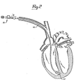
- Referring now to the preferred embodiment of the invention depicted in Figure 1, there is shown an intravascular endocardical lead comprising an
elongated lead 10, a distalelectrode end portion 12, and a proximalterminal end portion 13. The lead, in unipolar configuration, comprises a closely wound, coiledconductor 14 in the form of a spring spirally wound about and along the axis of the conductor. Thespring coil 14 extends through the length oflead 10 in a lumen of a jacket or sleeve 16 of electrically insulating material. - A tissue securing member in the form of a relatively rigid circular corkscrew or
helix 42 is provided having aproximal end 44 of several closely wound turns located in thechamber 34 toward the proximal end thereof. Helix 42 has a sharpenedtip 48. - The stylet used in the preferred embodiment of the invention disclosed herein is disclosed in a co-pending European Patent Application No. 80300035.5 published 23rd July 1980 under No. 0013604. The corrosion resistant stylet disclosed therein has a reduced diameter portion near the distal end to facilitate transmission of the rotational torque by the stylet in situations where the stylet and lead assembly are sharply bent in the vicinity of the distal end of the lead.
- If the above described flexible tip stylet is to be used to lodge the helix into the body tissue, it may be necessary to utilize a standard uniform diameter stylet to stiffen the lead to facilitate insertion of the lead through the venous system and into the chamber of the heart where the
helix 42 is desired to be implanted. After the lead is inserted and positioned, the insertion stylet is removed and the flexible tip stylet may then be inserted and utilized for the remainder of the implanting process. Figure 2 shows the lead and stylet positioned for insertion of the helix in the apex of the right ventricle of the heart. - There is also provided in
chamber 34 at the distal end of thelead 10, a member 54 which takes the form of a piston having a generally circular cross section and has a proximal end at which is located a slotted head 58 and a distal end portion 60 which is somewhat smaller in cross sectional diameter than head 58. Head 58 had a slot 61 in the proximal end thereof which is adapted to receive the distal end ofstylet 20 which terminates at its distal end in ascrewdriver tip 62. When flexible tippedstylet 20 is fully inserted intolead 10 throughpin 18, itsscrewdriver tip portion 62 is firmly seated in slot 61. - Turning now to the
insertion assembly 21, which is shown mounted on the proximal end portion oflead 10 and is shown in enlarged and partially cut away form in Figure 3, theproximal end 70 ofstylet 20 is bent into a zig-zag portion which assures thatstylet 20 is permanently lodged inmolded shaft 72 and is positioned such thatstylet 20 extends fromshaft 72 along its axis. In the preferred embodiment shown, the proximal end ofstylet 20 has a diameter of 0.4 mm and the radii of the bends of theproximal end 70 ofstylet 20 are approximately 0.5 mm, while the "amplitude" of the zig-zag portion is approximately 1.5 mm. Shaft 72 has at its proximal end a moldedknob portion 74 which has a plurality ofprojections 80 from its surface to facilitate gripping of the knob and to permit its easy rotation. The insertion tool is molded from acetal resin in the preferred embodiment shown. - Rotation of
knob 74 andshaft 72 directly transmits rotational torque tostylet 20. Thescrewdriver blade tip 62 ofstylet 20 engages slot 61 in piston 54 and in turn rotates thepointed tip 48 of thehelix 42 of the lead to advance it into the body tissue against which the distal end of the lead was positioned when the rotation ofhelix 42 was commenced. -
Shaft 72 is shown in Figures 1 and 3 inserted in a guide andratchet portion 76. As shown in Figure 4 and the enlarged view in Figure 5, the guide andratchet portion 76 has a circular crosssection guide chamber 73 therein through which shaft 72 projects. A portion ofchamber 73 is molded with a tooth orpawl 78 which, whenshaft 72 is inserted inguide 76, bears upon the surface ofshaft 72. The surface ofshaft 72 has a longitudinal slot ornotch 82 along the axis ofshaft 72 which is engaged bytooth 78 ofguide 76 whenslot 82 is rotationally aligned withtooth 78. A plurality ofsuch slots 82 could be provided if desired. The relative dimensions of theshaft 72 are the ratchet andguide portion 76 are such that there is a positive tracking force exerted bytooth 78 on the surface ofshaft 72 as it is rotated. The depth ofnotch 82 and the shape oftooth 78 assure that a well-defined snap action is provided when thenotch 82 is aligned withtooth 78 upon rotation of the shaft. In addition to providing a tactile indication to the operator that a particular point in rotation has been reached, a detent action oftooth 78 andnotch 82 restrains inadvertent further rotation of the stylet in either rotational direction. If the operator desires to release the detent, the upper projecting "ear"portions shaft 72 is positioned to removetooth 78 from engagement withnotch 82. - In summary,
lead 10 may be positioned in the appropriate position in the heart using a conventional stylet which is then removed. After the -reaa- is positioned, theinsertion tool 21 is mounted thereon,stylet 20 as described herein is inserted through thetool 21 and intolead 10, andscrewdriver tip 62 ofstylet 20 engages slot 61 of piston 58. Theshaft 72 is then inserted intoguide chamber 73 ofguide 76.Handle 74 is then rotated in the correction direction to causehelix 42 to advance into the tissue against which the distal end oflead 10 was placed. A distinct click is produced upon each full rotation ofshaft 72 by the engagement ofpawl 78 andnotch 82 of the insertion tool and undesirable backlash or reverse rotation of the shaft is avoided by the detent action ofpawl 78 andnotch 82. After insertion is believed complete and the desired number of rotations have been counted, theears insertion tool 21 are squeezed together and the detent released to release residual torque and the knob rotated one-half turn while noting the degree of rotation resistance encountered. If the lead is adequately fixed, one may feel an increasing resistance while rotating the stylet. If the helix is properly lodged in the tissue of the organ, it can also be confirmed to move with the heart when viewed on a fluoroscope. The lead can also be lightly pulled while the fluoroscope is monitored to confirm that the helix continues to beat with the heart indicating that thehelix 42 is firmly implanted. - The cut away
portion 88 ofinsertion tool 21 permits access topin 18 oflead 10 during insertion and while the stylet is being rotated so that electrical measurements may be made or stimulation can be applied without removal of the stylet and its insertion tool. - Although a unipolar lead design has been illustrated in the description of the preferred embodiment, it will be understood that bipolar leads (that is a lead carrying two electrodes and conductors) may as readily utilize the novel structure of the present invention. It should be understood that although the
lead 10 has been described for use in a cardiac pacing system,lead 10 could as well be applied to other types of body stimulating systems. - It should be further understood, of course, that the foregoing disclosure relates only to the best mode known to the applicants of many possible modes of practising the invention and that numerous modifications may be made therein without departing from the scope of the invention as set forth in the appended claims.
Claims (5)
Applications Claiming Priority (2)
| Application Number | Priority Date | Filing Date | Title |
|---|---|---|---|
| US06/001,201 US4209019A (en) | 1979-01-05 | 1979-01-05 | Stylet insertion guide and rotation control device for use with body implantable lead |
| US1201 | 1997-12-30 |
Publications (2)
| Publication Number | Publication Date |
|---|---|
| EP0013605A1 EP0013605A1 (en) | 1980-07-23 |
| EP0013605B1 true EP0013605B1 (en) | 1982-02-17 |
Family
ID=21694876
Family Applications (1)
| Application Number | Title | Priority Date | Filing Date |
|---|---|---|---|
| EP80300036A Expired EP0013605B1 (en) | 1979-01-05 | 1980-01-04 | Stylet insertion assembly for body implantable lead |
Country Status (5)
| Country | Link |
|---|---|
| US (1) | US4209019A (en) |
| EP (1) | EP0013605B1 (en) |
| JP (1) | JPS5594264A (en) |
| CA (1) | CA1135586A (en) |
| DE (1) | DE3060190D1 (en) |
Cited By (13)
| Publication number | Priority date | Publication date | Assignee | Title |
|---|---|---|---|---|
| US5944715A (en) | 1996-06-20 | 1999-08-31 | Gyrus Medical Limited | Electrosurgical instrument |
| US6004319A (en) | 1995-06-23 | 1999-12-21 | Gyrus Medical Limited | Electrosurgical instrument |
| US6013076A (en) | 1996-01-09 | 2000-01-11 | Gyrus Medical Limited | Electrosurgical instrument |
| US6015406A (en) | 1996-01-09 | 2000-01-18 | Gyrus Medical Limited | Electrosurgical instrument |
| US6027501A (en) | 1995-06-23 | 2000-02-22 | Gyrus Medical Limited | Electrosurgical instrument |
| US6090106A (en) | 1996-01-09 | 2000-07-18 | Gyrus Medical Limited | Electrosurgical instrument |
| US6093186A (en) | 1996-12-20 | 2000-07-25 | Gyrus Medical Limited | Electrosurgical generator and system |
| US6210405B1 (en) | 1996-06-20 | 2001-04-03 | Gyrus Medical Limited | Under water treatment |
| US6261286B1 (en) | 1995-06-23 | 2001-07-17 | Gyrus Medical Limited | Electrosurgical generator and system |
| US6277114B1 (en) | 1998-04-03 | 2001-08-21 | Gyrus Medical Limited | Electrode assembly for an electrosurical instrument |
| US6565561B1 (en) | 1996-06-20 | 2003-05-20 | Cyrus Medical Limited | Electrosurgical instrument |
| US6780180B1 (en) | 1995-06-23 | 2004-08-24 | Gyrus Medical Limited | Electrosurgical instrument |
| US7647123B2 (en) | 1996-08-13 | 2010-01-12 | Oratec Interventions, Inc. | Method for treating intervertebral discs |
Families Citing this family (68)
| Publication number | Priority date | Publication date | Assignee | Title |
|---|---|---|---|---|
| US4381013A (en) * | 1981-03-19 | 1983-04-26 | Medtronic, Inc. | "J" Stylet wire |
| USRE32227E (en) * | 1981-03-19 | 1986-08-19 | Medtronic, Inc. | "J" Stylet wire |
| US4624266A (en) * | 1983-12-19 | 1986-11-25 | Daig Corporation | Introducer tool for screw-in lead |
| US4646755A (en) * | 1985-10-21 | 1987-03-03 | Daig Corporation | Introducer tool for endocardial screw-in lead |
| US4827940A (en) * | 1987-04-13 | 1989-05-09 | Cardiac Pacemakers, Inc. | Soluble covering for cardiac pacing electrode |
| JPH0417534Y2 (en) * | 1987-05-21 | 1992-04-20 | ||
| US5003992A (en) * | 1989-08-23 | 1991-04-02 | Holleman Timothy W | Atraumatic screw-in lead |
| US4953564A (en) * | 1989-08-23 | 1990-09-04 | Medtronic, Inc. | Screw-in drug eluting lead |
| US5056516A (en) * | 1989-11-02 | 1991-10-15 | Intermedics, Inc. | Implantable endocordial lead with torque-transmitting lanyard |
| US5129404A (en) * | 1990-12-21 | 1992-07-14 | Intermedics, Inc. | Implantable endocardial lead with retractable fixation apparatus |
| US5139033A (en) * | 1991-03-04 | 1992-08-18 | Cardiac Pacemakers, Inc. | Sutureless myocardial lead implantation device |
| US5174303A (en) * | 1991-05-03 | 1992-12-29 | Intermedics, Inc. | Pacer lead with replaceable sensor |
| US5228455A (en) * | 1991-05-20 | 1993-07-20 | Siemens Pacesetter, Inc. | Implant tool for extendable/retractable positive fixation lead |
| US5324325A (en) * | 1991-06-27 | 1994-06-28 | Siemens Pacesetter, Inc. | Myocardial steroid releasing lead |
| US5231996A (en) * | 1992-01-28 | 1993-08-03 | Medtronic, Inc. | Removable endocardial lead |
| US5447533A (en) * | 1992-09-03 | 1995-09-05 | Pacesetter, Inc. | Implantable stimulation lead having an advanceable therapeutic drug delivery system |
| US5374286A (en) * | 1993-03-31 | 1994-12-20 | Medtronic, Inc. | Torque indicator for fixed screw leads |
| US5431649A (en) * | 1993-08-27 | 1995-07-11 | Medtronic, Inc. | Method and apparatus for R-F ablation |
| US5456708A (en) * | 1993-10-28 | 1995-10-10 | Pacesetter, Inc. | Rotatable pin, screw-in pacing and sensing lead having improved tip and fluidic seal |
| US5741321A (en) * | 1996-01-11 | 1998-04-21 | Medtronic, Inc. | Active fixation medical electrical lead having improved turning tool |
| US6755794B2 (en) | 2000-04-25 | 2004-06-29 | Synovis Life Technologies, Inc. | Adjustable stylet |
| US6375654B1 (en) * | 2000-05-19 | 2002-04-23 | Cardiofocus, Inc. | Catheter system with working portion radially expandable upon rotation |
| US6602262B2 (en) * | 2000-06-02 | 2003-08-05 | Scimed Life Systems, Inc. | Medical device having linear to rotation control |
| SE0102353D0 (en) * | 2001-06-29 | 2001-06-29 | St Jude Medical | A styled unit |
| US6776765B2 (en) * | 2001-08-21 | 2004-08-17 | Synovis Life Technologies, Inc. | Steerable stylet |
| US6745079B2 (en) | 2001-11-07 | 2004-06-01 | Medtronic, Inc. | Electrical tissue stimulation apparatus and method |
| FR2835189B1 (en) * | 2002-01-25 | 2004-03-19 | Ela Medical Sa | NECESSARY TO SET UP AN INTRACARDIAC STIMULATION OR DEFIBRILLATION PROBE OF THE RETRACTABLE SCREW TYPE |
| US7151965B2 (en) * | 2002-07-19 | 2006-12-19 | Oscor Inc. | Device and method for delivering cardiac leads |
| EP1428550A1 (en) * | 2002-12-13 | 2004-06-16 | P.A. & M. S.p.A. | Single pacemaker catheter electrode for the biventricular cardiac electrostimulation |
| US7509172B2 (en) * | 2003-04-23 | 2009-03-24 | Cardiac Pacemakers, Inc. | Stabilizing guide wire apparatus for use with implantable device |
| US8246974B2 (en) * | 2003-05-02 | 2012-08-21 | Surmodics, Inc. | Medical devices and methods for producing the same |
| EP1633320A2 (en) * | 2003-05-02 | 2006-03-15 | SurModics, Inc. | Implantable controlled release bioactive agent delivery device |
| US20040260371A1 (en) * | 2003-06-19 | 2004-12-23 | John Greenland | Stabilizing apparatus for use with implantable leads |
| US20050177199A1 (en) * | 2004-02-09 | 2005-08-11 | Cardiac Pacemakers, Inc. | PSA cable and connector for quadripolar lead terminal |
| US20050228457A1 (en) * | 2004-04-07 | 2005-10-13 | Mo Jafari | Finishing wire compatible with multiple components |
| US20050228458A1 (en) * | 2004-04-07 | 2005-10-13 | Mo Jafari | Finishing wire assembly having variable insertion length and method therefor |
| WO2006002366A2 (en) * | 2004-06-24 | 2006-01-05 | Surmodics, Inc. | Biodegradable ocular devices, methods and systems |
| US20060034891A1 (en) * | 2004-08-12 | 2006-02-16 | Laurie Lawin | Biodegradable controlled release bioactive agent delivery device |
| US20060089569A1 (en) * | 2004-10-26 | 2006-04-27 | Soukup Thomas M | Articulator with adjustable stiffness distal portion |
| US20070156209A1 (en) * | 2005-01-14 | 2007-07-05 | Co-Repair, Inc. | System for the treatment of heart tissue |
| US20060184105A1 (en) * | 2005-02-15 | 2006-08-17 | Townsend Gregory L | Thin wall catheter and method of placing same |
| US7753696B2 (en) * | 2005-05-12 | 2010-07-13 | Cardiac Pacemakers, Inc. | Lead terminal multi-tool |
| US7892186B2 (en) * | 2005-12-09 | 2011-02-22 | Heraeus Materials S.A. | Handle and articulator system and method |
| US8170692B2 (en) * | 2006-08-29 | 2012-05-01 | Pacesetter, Inc. | Implant tool for active fixation lead |
| US7881806B2 (en) * | 2006-10-31 | 2011-02-01 | Medtronic, Inc. | Medical lead delivery device |
| US8644955B2 (en) | 2007-03-30 | 2014-02-04 | Medtronic, Inc. | Controller for a medical lead delivery device |
| US9199075B1 (en) | 2008-02-07 | 2015-12-01 | Respicardia, Inc. | Transvascular medical lead |
| US8469971B2 (en) * | 2008-08-12 | 2013-06-25 | Boston Scientific Neuromodulation Corporation | Stylet for guiding leads of implantable electric stimulation systems and methods of making and using |
| US20100189765A1 (en) * | 2008-11-26 | 2010-07-29 | Erickson Signe R | Implantable ocular drug delivery device and methods |
| WO2010104643A2 (en) | 2009-03-12 | 2010-09-16 | Cardiac Pacemakers, Inc. | Thin profile conductor assembly for medical device leads |
| US9254380B2 (en) * | 2009-10-19 | 2016-02-09 | Cardiac Pacemakers, Inc. | MRI compatible tachycardia lead |
| US9302092B2 (en) * | 2009-12-30 | 2016-04-05 | Cardiac Pacemakers, Inc. | Multi-function lead implant tool |
| JP5551794B2 (en) | 2009-12-30 | 2014-07-16 | カーディアック ペースメイカーズ, インコーポレイテッド | Medical device leads safe under MRI conditions |
| US8391994B2 (en) | 2009-12-31 | 2013-03-05 | Cardiac Pacemakers, Inc. | MRI conditionally safe lead with low-profile multi-layer conductor for longitudinal expansion |
| EP2519305B1 (en) | 2009-12-31 | 2017-07-05 | Cardiac Pacemakers, Inc. | Mri conditionally safe lead with multi-layer conductor |
| US9083129B2 (en) | 2010-07-14 | 2015-07-14 | Cardiac Pacemakers, Inc. | Multipolar lead evaluation device |
| US20130245710A1 (en) * | 2012-03-19 | 2013-09-19 | Cardiac Pacemakers, Inc. | Integral stimulation lead |
| MX351261B (en) | 2012-06-01 | 2017-10-06 | Surmodics Inc | Apparatus and method for coating balloon catheters. |
| US8954168B2 (en) | 2012-06-01 | 2015-02-10 | Cardiac Pacemakers, Inc. | Implantable device lead including a distal electrode assembly with a coiled component |
| US9827401B2 (en) | 2012-06-01 | 2017-11-28 | Surmodics, Inc. | Apparatus and methods for coating medical devices |
| WO2014035487A1 (en) * | 2012-08-27 | 2014-03-06 | Cardiac Pacemakers, Inc. | Compound-shaped stylet for torque transmission |
| US8958889B2 (en) | 2012-08-31 | 2015-02-17 | Cardiac Pacemakers, Inc. | MRI compatible lead coil |
| CN104736196B (en) | 2012-10-18 | 2017-06-16 | 心脏起搏器股份公司 | Sensing element for providing Magnetic resonance imaging compatibility in implantable medical device lead |
| US11090468B2 (en) | 2012-10-25 | 2021-08-17 | Surmodics, Inc. | Apparatus and methods for coating medical devices |
| EP3110499B1 (en) | 2014-02-26 | 2018-01-24 | Cardiac Pacemakers, Inc. | Construction of an mri-safe tachycardia lead |
| WO2020112816A1 (en) | 2018-11-29 | 2020-06-04 | Surmodics, Inc. | Apparatus and methods for coating medical devices |
| US11819590B2 (en) | 2019-05-13 | 2023-11-21 | Surmodics, Inc. | Apparatus and methods for coating medical devices |
| US11944828B2 (en) | 2020-09-24 | 2024-04-02 | Medtronic, Inc. | Rotatable adapter for connecting implantable medical leads to test devices |
Family Cites Families (8)
| Publication number | Priority date | Publication date | Assignee | Title |
|---|---|---|---|---|
| US3416533A (en) * | 1966-05-20 | 1968-12-17 | Gen Electric | Conductive catheter |
| CH545624A (en) * | 1970-12-15 | 1974-02-15 | ||
| US3844292A (en) * | 1972-06-09 | 1974-10-29 | Medtronic Inc | Intravascular lead assembly |
| US3991762A (en) * | 1974-09-30 | 1976-11-16 | Radford F Richard | Aspirating device for patient ventilation apparatus |
| US3974834A (en) * | 1975-04-23 | 1976-08-17 | Medtronic, Inc. | Body-implantable lead |
| US4027678A (en) * | 1975-11-19 | 1977-06-07 | Vitatron Medical B.V. | Pacing system with connector for connecting electrode to pacer |
| US4086715A (en) * | 1976-04-21 | 1978-05-02 | Blonigen Quentin P | Multiple rating device |
| US4106512A (en) * | 1976-12-16 | 1978-08-15 | Medtronic, Inc. | Transvenously implantable lead |
-
1979
- 1979-01-05 US US06/001,201 patent/US4209019A/en not_active Expired - Lifetime
- 1979-12-25 JP JP16909979A patent/JPS5594264A/en active Granted
-
1980
- 1980-01-04 DE DE8080300036T patent/DE3060190D1/en not_active Expired
- 1980-01-04 CA CA000343039A patent/CA1135586A/en not_active Expired
- 1980-01-04 EP EP80300036A patent/EP0013605B1/en not_active Expired
Cited By (21)
| Publication number | Priority date | Publication date | Assignee | Title |
|---|---|---|---|---|
| US6174308B1 (en) | 1995-06-23 | 2001-01-16 | Gyrus Medical Limited | Electrosurgical instrument |
| US6004319A (en) | 1995-06-23 | 1999-12-21 | Gyrus Medical Limited | Electrosurgical instrument |
| US6780180B1 (en) | 1995-06-23 | 2004-08-24 | Gyrus Medical Limited | Electrosurgical instrument |
| US6416509B1 (en) | 1995-06-23 | 2002-07-09 | Gyrus Medical Limited | Electrosurgical generator and system |
| US6027501A (en) | 1995-06-23 | 2000-02-22 | Gyrus Medical Limited | Electrosurgical instrument |
| US6056746A (en) | 1995-06-23 | 2000-05-02 | Gyrus Medical Limited | Electrosurgical instrument |
| US6364877B1 (en) | 1995-06-23 | 2002-04-02 | Gyrus Medical Limited | Electrosurgical generator and system |
| US6261286B1 (en) | 1995-06-23 | 2001-07-17 | Gyrus Medical Limited | Electrosurgical generator and system |
| US6234178B1 (en) | 1996-01-09 | 2001-05-22 | Gyrus Medical Limited | Electrosurgical instrument |
| US6090106A (en) | 1996-01-09 | 2000-07-18 | Gyrus Medical Limited | Electrosurgical instrument |
| US6015406A (en) | 1996-01-09 | 2000-01-18 | Gyrus Medical Limited | Electrosurgical instrument |
| US6013076A (en) | 1996-01-09 | 2000-01-11 | Gyrus Medical Limited | Electrosurgical instrument |
| US6210405B1 (en) | 1996-06-20 | 2001-04-03 | Gyrus Medical Limited | Under water treatment |
| US5944715A (en) | 1996-06-20 | 1999-08-31 | Gyrus Medical Limited | Electrosurgical instrument |
| US6482202B1 (en) | 1996-06-20 | 2002-11-19 | Gyrus Medical Limited | Under water treatment |
| US6565561B1 (en) | 1996-06-20 | 2003-05-20 | Cyrus Medical Limited | Electrosurgical instrument |
| US7647123B2 (en) | 1996-08-13 | 2010-01-12 | Oratec Interventions, Inc. | Method for treating intervertebral discs |
| US8187312B2 (en) | 1996-08-13 | 2012-05-29 | Neurotherm, Inc. | Method for treating intervertebral disc |
| US8226697B2 (en) | 1996-08-13 | 2012-07-24 | Neurotherm, Inc. | Method for treating intervertebral disc |
| US6093186A (en) | 1996-12-20 | 2000-07-25 | Gyrus Medical Limited | Electrosurgical generator and system |
| US6277114B1 (en) | 1998-04-03 | 2001-08-21 | Gyrus Medical Limited | Electrode assembly for an electrosurical instrument |
Also Published As
| Publication number | Publication date |
|---|---|
| CA1135586A (en) | 1982-11-16 |
| US4209019A (en) | 1980-06-24 |
| EP0013605A1 (en) | 1980-07-23 |
| JPS5594264A (en) | 1980-07-17 |
| JPS6241030B2 (en) | 1987-09-01 |
| DE3060190D1 (en) | 1982-03-25 |
Similar Documents
| Publication | Publication Date | Title |
|---|---|---|
| EP0013605B1 (en) | Stylet insertion assembly for body implantable lead | |
| US4350169A (en) | Flexible tip stiffening stylet for use with body implantable lead | |
| US4624266A (en) | Introducer tool for screw-in lead | |
| US4217913A (en) | Body-implantable lead with protected, extendable tissue securing means | |
| EP0787505B1 (en) | Active fixation medical electrical lead having improved turning tool | |
| US4381013A (en) | "J" Stylet wire | |
| AU660481B2 (en) | Implantable lead system | |
| JP2838500B2 (en) | Human implantable medical electrical lead | |
| US4146036A (en) | Body-implantable lead with protector for tissue securing means | |
| US5020545A (en) | Cardiac lead assembly and method of attaching a cardiac lead assembly | |
| CA1085932A (en) | Body-implantable lead | |
| EP1284783B1 (en) | Introducer system for medical electrical lead | |
| US4026303A (en) | Endocardial pacing electrode | |
| EP0009530B1 (en) | Atrial lead | |
| US4046151A (en) | Body implantable lead with stiffening stylet | |
| US4628943A (en) | Bipolar screw-in packing lead assembly | |
| AU6943494A (en) | Steerable stylet and manipulative handle assembly | |
| EP0773813A1 (en) | Lead with stylet capture member | |
| EP0715865A2 (en) | Steerable stylet assembly | |
| EP0013604A1 (en) | Flexible tip stiffening stylet for body implantable lead | |
| USRE32227E (en) | "J" Stylet wire | |
| CA1154833A (en) | Endocardial pacing lead | |
| Dutcher et al. | J" Stylet wire | |
| SU1674859A1 (en) | Endocardiac electrode |
Legal Events
| Date | Code | Title | Description |
|---|---|---|---|
| PUAI | Public reference made under article 153(3) epc to a published international application that has entered the european phase |
Free format text: ORIGINAL CODE: 0009012 |
|
| AK | Designated contracting states |
Designated state(s): CH DE FR GB IT NL SE |
|
| ITCL | It: translation for ep claims filed |
Representative=s name: SOCIETA' ITALIANA BREVETTI S.P.A. |
|
| 17P | Request for examination filed | ||
| DET | De: translation of patent claims | ||
| ITF | It: translation for a ep patent filed |
Owner name: BARZANO' E ZANARDO ROMA S.P.A. |
|
| GRAA | (expected) grant |
Free format text: ORIGINAL CODE: 0009210 |
|
| AK | Designated contracting states |
Designated state(s): CH DE FR GB IT NL SE |
|
| PG25 | Lapsed in a contracting state [announced via postgrant information from national office to epo] |
Ref country code: CH Effective date: 19820217 |
|
| REF | Corresponds to: |
Ref document number: 3060190 Country of ref document: DE Date of ref document: 19820325 |
|
| REG | Reference to a national code |
Ref country code: CH Ref legal event code: PL |
|
| ITTA | It: last paid annual fee | ||
| PGFP | Annual fee paid to national office [announced via postgrant information from national office to epo] |
Ref country code: FR Payment date: 19921210 Year of fee payment: 14 |
|
| PGFP | Annual fee paid to national office [announced via postgrant information from national office to epo] |
Ref country code: SE Payment date: 19921211 Year of fee payment: 14 Ref country code: DE Payment date: 19921211 Year of fee payment: 14 |
|
| PGFP | Annual fee paid to national office [announced via postgrant information from national office to epo] |
Ref country code: GB Payment date: 19921231 Year of fee payment: 14 |
|
| PGFP | Annual fee paid to national office [announced via postgrant information from national office to epo] |
Ref country code: NL Payment date: 19930131 Year of fee payment: 14 |
|
| PG25 | Lapsed in a contracting state [announced via postgrant information from national office to epo] |
Ref country code: GB Effective date: 19940104 |
|
| PG25 | Lapsed in a contracting state [announced via postgrant information from national office to epo] |
Ref country code: SE Effective date: 19940105 |
|
| PG25 | Lapsed in a contracting state [announced via postgrant information from national office to epo] |
Ref country code: NL Effective date: 19940801 |
|
| GBPC | Gb: european patent ceased through non-payment of renewal fee |
Effective date: 19940104 |
|
| NLV4 | Nl: lapsed or anulled due to non-payment of the annual fee | ||
| PG25 | Lapsed in a contracting state [announced via postgrant information from national office to epo] |
Ref country code: FR Effective date: 19940930 |
|
| PG25 | Lapsed in a contracting state [announced via postgrant information from national office to epo] |
Ref country code: DE Effective date: 19941001 |
|
| REG | Reference to a national code |
Ref country code: FR Ref legal event code: ST |
|
| EUG | Se: european patent has lapsed |
Ref document number: 80300036.3 Effective date: 19940810 |
|
| PLBE | No opposition filed within time limit |
Free format text: ORIGINAL CODE: 0009261 |
|
| STAA | Information on the status of an ep patent application or granted ep patent |
Free format text: STATUS: NO OPPOSITION FILED WITHIN TIME LIMIT |