EP0017090A1 - Method and apparatus for sensing a line of characters, and character recognition apparatus - Google Patents
Method and apparatus for sensing a line of characters, and character recognition apparatus Download PDFInfo
- Publication number
- EP0017090A1 EP0017090A1 EP80101459A EP80101459A EP0017090A1 EP 0017090 A1 EP0017090 A1 EP 0017090A1 EP 80101459 A EP80101459 A EP 80101459A EP 80101459 A EP80101459 A EP 80101459A EP 0017090 A1 EP0017090 A1 EP 0017090A1
- Authority
- EP
- European Patent Office
- Prior art keywords
- characters
- line
- baseline
- character
- sensor elements
- Prior art date
- Legal status (The legal status is an assumption and is not a legal conclusion. Google has not performed a legal analysis and makes no representation as to the accuracy of the status listed.)
- Granted
Links
Images

Classifications
-
- G—PHYSICS
- G06—COMPUTING; CALCULATING OR COUNTING
- G06V—IMAGE OR VIDEO RECOGNITION OR UNDERSTANDING
- G06V30/00—Character recognition; Recognising digital ink; Document-oriented image-based pattern recognition
- G06V30/10—Character recognition
- G06V30/14—Image acquisition
- G06V30/146—Aligning or centring of the image pick-up or image-field
- G06V30/1475—Inclination or skew detection or correction of characters or of image to be recognised
- G06V30/1478—Inclination or skew detection or correction of characters or of image to be recognised of characters or characters lines
-
- G—PHYSICS
- G06—COMPUTING; CALCULATING OR COUNTING
- G06V—IMAGE OR VIDEO RECOGNITION OR UNDERSTANDING
- G06V30/00—Character recognition; Recognising digital ink; Document-oriented image-based pattern recognition
- G06V30/10—Character recognition
Definitions
- This invention is applicable in character recognition systems, one example being Optical Character Recognition (OCR) systems. It particularly concerns determining the baseline of a line of characters, which may include characters of different height, characters extending below the baseline, characters with subscripts, or underlined characters as an aid to the process of recognising the characters.
- OCR Optical Character Recognition
- a scanning means such as a flying spot optical scanner scans a medium on which characters are stored and provides one type of output electrical signal in response to the scan of the character and another type of output electrical signal in response to a scan of the background.
- the character recognition logic receives the scanner output signals and makes a decision as to the character identity.
- optical scanners may distinguish black characters from white background, or vice versa, and magnetic scanners may distinguish between characters written with magnetic ink and the nonmagnetic background. Since the signals from the scanner output only inform the logic whether the scanner is instantaneously viewing a spot on the character or a spot on the background, it is necessary to provide position signals to the recognition logic.
- the position information supplied corresponds to the movement of the scanner.
- the scanner usually performs a patterned scan which covers a certain area. In some systems, an entire line may be scanned, using a buffer for storing the information. In other systems, scanning occurs one vertical line of a character at a time. In these latter systems, the patterned scan of one character in a line is followed by the patterned scan of the next character in the line, and so on. When the scan reaches the end of a line it moves to the next line and begins again.
- a computer determines for each numeral the coordinates of a respective reference starting point, which coordinates are used by a recognition unit in the subsequent recognition process for the respective numeral.
- the present invention is concerned with determining baseline as such, of a line of characters which may include characters of different heights, characters.extending below the baseline, characters with subscripts, or underlined characters.
- a method of sensing printed characters on a document with a scanning array comprising a plurality of sensor elements, each of said sensor elements producing an output indicative of the presence of a character portion or background portion on said document, said method comprising the steps of producing relative motion between said document and said scanning array, selecting certain of said sensor elements to define a baseline searching window, determining from the outputs of said sensor elements which define said baseline searching window the position of the lowest character portion in said window, and utilizing said lowest character portion information as a measure of the position of said baseline.
- a method of sensing a line of characters in which an array of sensor elements relatively sweeps along said line, each sensor element producing an output indicative of whether it currently senses a part of a character, or background, the lowest character parts of the sensed characters, which characters are of the same height and do not extend below a common baseline, being determined from the outputs of the sensor elements, characterized in that the method determines the baseline of a line of characters which may also include characters of different height, characters extending below the baseline, characters with subscripts, or underlined characters, in which the lowest character parts of the character portions occurring in a narrow band extending along the line of characters and including the baseline are determined from the outputs of certain ones of the sensor elements, the alignment and width of the band being such that any underlinings of the characters in the line are outside the band, whereas characters which extend below the baseline or subscripts of characters, and which are wholly or partly intersected by the band, provide apparent lowest character parts at the bottom edge of the band, or actual lowest characterparts within the
- the above method determines the lowest parts of those characters, which parts occur in said narrow band.
- each character has a specific vertical position relative to a common writing line or baseline. Most characters are located right on the baseline, for example, A, E, P, whereas some have portions extending below the baseline, for example, j, g, /, etc.
- two techniques are used which can be regarded as detecting the imaginary baseline.
- the first which may be called coarse prediction, involves making a horizontal projection frequency distribution or density histogram of the scanned material. If such a histogram is made for successive part lengths of a line of characters, say for every 10 consecutive characters, a peak usually is found at the lower portion of each histogram.
- That peak is a good estimate of the averaged baseline elevation for the associated group of characters.
- An averaged ba'seline elevation for an entire print line can be similarly estimated from a total horizontal density histogram, or by taking the average of the set of baseline elevation estimates detected from each partial line histogram. This set of baseline elevation estimates can also be used to reveal some information about the skew of the line.
- the second technique used may be called detail detection, and in this technique the outputs of certain ones of the sensor elements, forming an imaginary window, are examined to search for the baseline of each character image, allowing some possibility of skew of the print line.
- an estimated baseline elevation can be determined by the method of coarse prediction as described above to determine which sensor elements form the window for that line, or it can be introduced manually by aligning the document to a horizontal reference.
- the baseline elevation can be directly estimated by calculating the difference of the standard line spacing, say 1/6 inch, from the baseline elevation used for the previous line.
- the window includes the baseline and its immediate neighborhood. The height of the window allows the possibility of a limited amount of skew of the baseline.
- the lowest black bit found in the window for each vertical scan of the line is identified and the baseline is determined from the succession of these lowest black bits.
- the average of the lowest black bit positions over a number of characters can be treated as the baseline elevation for the associated characters. This averaging technique can minimize error that might arise from characters with portions extending below the baseline.
- Piecewise baseline information across an entire print line will reveal the skew of that line.
- Such skew measurement e.g. using the coarse technique mentioned above, is useful in enabling the OCR system to decide whether realignment of the document is required to ⁇ . correct any severe skew exceeding a predetermined value prior to further scanning. Skew information may also assist in segmentation.
- Baseline information including possible skew may be used to define the domain for horizontal segmentation.
- Horizontal segmentation means the segmentation required to separate the horizontally neighboring characters printed on one line.
- vertical segmentation is to separate a character from any images associated with the previous or the following print line.
- the presence of contiguous underscores can make adjacent character images look like one character image. It may be desirable to separate and isolate an underscore from the character fields both above and below that underscore when horizontal segmentation is taking place. In other words, referring to the standard 10-pitch Courier 72 font design, underscore is located at about 49 mils below the baseline.
- the baseline information and maximum character height, or line spacing can be utilized to exclude underscores when defining the upper and lower boundaries of the domain for horizontal segmentation of the line. Similar techniques can be applied to segment domains for sub und super scripts.
- Baseline information is also useful in recognising individual characters. Since the baseline is determined from a plurality of characters in a line that determination will be less sensitive to edge noise i.e. print faults of individual characters in the line which might make those characters difficult to recognise. Moreover, baseline information can be used by the recognition logic, for example to distinguish between an apostrophe and a comma which have the same shape for some fonts, or between certain similarly shaped lowercase and uppercase letters. For these problems, baseline positional information is helpful to distinguish the-two.
- the baseline position allows the position of the next baseline to be predicted according to the standard line-to-line distance, for example, six lines per inch. As a result of such prediction, the next baseline searching window can be properly located.
- the actual baseline measurement can be used to update the prediction.
- a linear scanner array is shown schematically at 11 in relation to a portion of a line of print to be scanned.
- Array 11 may be of any suitable type used for optical character recognition such as a Reticon C Series Solid State Line Scanner, manufactured by Reticon Corp., Mt. View, California.
- scanner 11 includes a suitable number, such as 64, of separate light sensor elements arranged vertically of the line to be scanned. Each element in the array 11 produces an output signal which is a measure of the amount of light reflected from the portion of the scanned document associated with that element.
- the output signals from the elements of array 11 are converted to signals indicating either a light or dark condition of the scanned area, and in the present description it will be assumed that signals from dark or printed areas i.e. character parts, of the scanned document will produce a binary "one" or black bit signal, while signals from light or background areas of the scanned document produce a binary "zero".
- Array 11 is arranged to perform a vertical scan which extends above and below the line to be scanned, as represented by lla..
- these elements are identified as llb and are located in part of the lower half of array 11.
- 6 of these elements can be used for the group lIb.
- FIG. 1 will be discussed further in connection with detail baseline detection.
- FIG. 2 is a series of horizontal density histograms for a scanned line of characters, each separate frame 2A, 2B, 2C, 2D representing a consecutive scan of the same length, including a number of characters, along the line.
- Each frame contains a plot of the number of picture element signals received by the scanner as a function of character or line height above a reference line which is parallel to the lines sensed by the sensor elements.
- the peak in the lower portion of the histogram is used as the predicted location of the baseline.
- point 3A represents the predicted baseline elevation
- point 3B represents the predicted baseline elevation for frame 2B, etc.
- the points 3A, 3B, 3C and 3D are equally spaced.
- a predicted mean baseline elevation for the entire line can be generated, as represented by line 3E in frame 2D (mid-way between the heights of points 38 and 3C), and the skew for the predicted baseline is represented by the difference between line 3E and the line connecting points 3A, 3B, 3C and 3D.
- This technique assumes that the line of characters is not continuously underlined.
- FIG. 3 illustrates a particular embodiment of the invention in the form of character recognition apparatus.
- the output from scanner 11 is supplied to a threshold buffer 12 which converts the signals from the sensors in array 11 to binary ones or zeroes corresponding to signals from dark or light areas of the scanned document, as discussed above, and temporarily stores them.
- the buffer 12 provides an input to a horizontal projection histogram generator 13, which is capable of appropriately counting the signals from buffer 12 and generating signals corresponding to the histograms of FIG. 2 indicative of the location of the peak value in each segment of the line of characters.
- Generator 13 may also indicate the location of the peak value for the entire scanned line.
- the output from generator 13 is supplied as the input to a baseline prediction and skew measurement network 14 which utilizes the signal from generator 13 to produce predicted values for the baseline location and a measure of the skew of the predicted baseline, as shown in FIG. 2.
- the output from network 14 is supplied as an input to a character recognition processor 16 which may utilize this information in various ways. For example if the predicted baseline skew measurement exceeds, a predetermined value, the operation of the apparatus can be halted, automatically, or manually in response to a warning signal, to allow repositioning of the line of characters being sensed e.g. by repositioning the document being sensed.
- the output from network 14 is also supplied to predicted baseline position generator 17, which generates a predicted baseline position signal representing, for example, the line 18 in FIG. 1.
- This last signal controls a search window selection circuit 31 which in effect determines which group of the sensor elements of array 11 shall be the search window for a particular line scan.
- the buffer 12 is re-read and re-supplies its signals, in respect of that same first line, to enable detection of the lowest black bit position occurring in the search window per vertical line scan by array 11 as will be explained.
- the search window for the next line is determined to correspond to the predicted baseline position signal for the first line, it being assumed that the array 11 relatively moves a standard line spacing between lines. This search window determination is available when said next line is scanned, so that the need to re-read buffer 12 for this line or subsequent lines, is avoided.
- the array 11 can be manually positioned to visually align the midpoint of a predetermined group of sensor elements approximately with the baseline of that first line, and search window selection circuit 31 can produce an output corresponding to the selection of that predetermined group of sensor elements as the search window.
- the predicted baseline position for the next line is determined as explained above, using the coarse baseline prediction technique, which determines the search window for the next line.
- the line of characters may include characters of the same height which do not extend below the baseline, characters of different height, characters extending below the baseline, characters with subscripts, or underlined characters,
- the lowest character parts of the character portions occurring in a narrow band extending along the line of characters and including the baseline are determined from the outputs of certain ones i.e. the search window, of the sensor elements. Characters which extend below the baseline, or subscripts of characters, and which are wholly or partly intersected by the band, provide apparent lowest character parts at the bottom edge of the band, or actual lowest character parts within the band.
- Circuitry for detecting the lowest black bit position is shown in FIG. 3 and includes a shift register 26 which receives the digitized scanner output signals from buffer 12. Shift register 26 operates to shift the bits in the buffer output by one position and to supply the shifted bits as one input B to an exclusive OR gate 27. Gate 27 receives the output of buffer 12 as another input A.
- the output of gate 27 is supplied as one input C to an AND gate 28, gate 28 also receiving the input A from buffer 12.
- the output of gate 28 is supplied as an input D to an AND gate 29 which receives an input E from search window selection circuitry 31.
- Circuitry 31 is controlled by the indication of predicted baseline position from box 17 and operates to open gate 29 during the period of each vertical scan when those signals of output A associated with the sensor elements in array 11 functioning as the search window are being received by gate 29.
- the output F of gate 29 is a succession of lowest black bit positions occurring in the searching window, for the successive vertical scans, and these are supplied to an averaging circuit 32 which operates to average the lowest black bit position information for each scanned line or portion thereof to provide a determination of baseline position to OCR processor 16.
- the skew of the baseline can be obtained as previously explained. Segmentation and recognition of character images takes place in the OCR processor 16 in response to the determined baseline position, and to the sensor element outputs represented by the signals A transmitted from buffer 12 to processor 16 (by a line not shown in FIG. 3).
- FIG. 4 The operation of the detail baseline detection and its ability to separate underlinings from associated characters is shown in FIG. 4 in relation to scanning the line shown in FIG. 1.
- reference 36 identifies the lower left leg of the letter “A” in “A Boy is " shown in FIG. 1, and 37 identifies the underscoring which is under the "A” in this line.
- the positions of the sensor elements in array 11 are represented by the numbers 1-64 in the left hand column, only sensors 1-10 and 64 being shown to reduce the size of the figure.
- the outputs representing the signals A-F of FIG. 3 are shown in correspondingly labelled columns of FIG. 4.
- baseline searching window llb is shown in FIG. 4 and it can be seen that this window corresponds to the positions of sensor elements 5-10 in array 11.
- the signals in.the different columns A-F correspond to their values when scanner array 11 is at the position represented by line lla in FIG. 4.
- black bits are produced by sensor elements 6 and 7, representing the leg portion of the 36 of the letter "A”, and by sensor elements 2 and 3, representing the underscoring 37 beneath leg 36.
- the signals of column A are supplied to shift register 26 of FIG. 3 which operates to shift the signals left or up one position, as shown by the arrows.
- the signals represented by column B are supplied to exclusive OR gate 27 along with the signals A from buffer 12.
- The'output of gate 27 is represented by column C.in FIG. 4, containing bits in sensor element positions 2, 4, 6 and 8. This output C is then supplied to AND gate 28 along with signal A from buffer 12 to produce the signals shown in column D, having bits at positions 2 and 6.
- Signals D are supplied to AND gate 29 along with signals E from search window selection circuitry 31. Since the baseline searching window in this example is assumed to extend across sensor elements 5-10, circuitry 31 generates bits in positions 5-10 as shown in column E.
- the output F from gate 29 contains a single bit at sensor position 6 and it will be seen that this corresponds to the location of the bottom of leg 36 and hence represents the true baseline for leg 36 and letter "A".
- the apparatus can be regarded as operating to detect and locate the transition 36a from black to white (taking a downward scan) on the lower portion of leg 36 and to disregard the transition 36b from white to dark on the upper portion of leg 36.
- the apparatus can present the character itself to the recognition processor for recognition with or without the associated underscoring.
- the coarse baseline prediction involving determining one or more frequency distributions or histograms is not necessary, e.g. particularly with a line of characters which is continuously underlined.
- the scanner 11 can be manually positioned for the first line of characters corresponding to a predetermined search window for that first line, as already indicat p d.
- the search window for the next line will then be determined by controlling the search window selection circuit 31 according to a detail baseline elevation measure obtained from averaging circuits 32, it being assumed that scanner 11 is moved relatively one standard line spacing from the line of characters to the next line.
- averaging circuits 32 Other possibilities exist for the averaging circuits 32. For example a line fitting technique can be used to obtain the baseline from the succession of determined lowest character parts.
Abstract
Description
- This invention is applicable in character recognition systems, one example being Optical Character Recognition (OCR) systems. It particularly concerns determining the baseline of a line of characters, which may include characters of different height, characters extending below the baseline, characters with subscripts, or underlined characters as an aid to the process of recognising the characters.
- There are many types of character recognition systems known in the prior art. Typically in such systems, a scanning means such as a flying spot optical scanner scans a medium on which characters are stored and provides one type of output electrical signal in response to the scan of the character and another type of output electrical signal in response to a scan of the background. The character recognition logic receives the scanner output signals and makes a decision as to the character identity. As examples, optical scanners may distinguish black characters from white background, or vice versa, and magnetic scanners may distinguish between characters written with magnetic ink and the nonmagnetic background. Since the signals from the scanner output only inform the logic whether the scanner is instantaneously viewing a spot on the character or a spot on the background, it is necessary to provide position signals to the recognition logic. The position information supplied corresponds to the movement of the scanner.
- The scanner usually performs a patterned scan which covers a certain area. In some systems, an entire line may be scanned, using a buffer for storing the information. In other systems, scanning occurs one vertical line of a character at a time. In these latter systems, the patterned scan of one character in a line is followed by the patterned scan of the next character in the line, and so on. When the scan reaches the end of a line it moves to the next line and begins again.
- In an office environment, most documents are machine printed in single font style with a fixed pitch, usually on a typewriter. The documents have relatively good print quality and the text contains an inherent systematic grid pattern according to the fixed pitch and line spacing defined by the printing mechanism. Common baselines can be easily visualized from each line of printed characters. Baseline can be imagined for example as the bottom horizontal line to a line of uppercase characters, but also of course exists for lines comprising both upper and lower case characters. The fixed pitch property has been widely used for segmentation, but identification of baseline as such does not appear to have been mentioned in the prior art. Segmentation refers to the separation of one character or mark from another, either vertically or horizontally, and registration refers to the positioning of the scanning device over the character or mark to be sensed. Possible reasons for this failure to use baseline information in OCR applications are:
- 1. Some OCR systems are designed for recognizing a line of characters with a special mark at the beginning. The mark is used to assist the OCR machine locate the characters and keep the line skew under control.
- 2. For some OCR applications, the spacing between lines of printed characters is big enough and/or no underscores and sub or super scripts are allowed in the text. Therefore, character images will never touch vertically with any other characters above or below.
- Due to the intrinsic grid pattern existing on most office documents, segmentation may seem to be straight-forward. However, it still has its own typical problems on line skew which may be generated originally in the printing process or caused by unaligned scanning, and problems on vertically touching images due to the presence of underscore and sub or super scripts. As to registration, the regular simple boxing technique, in which the OCR scanner is physically moved to locate it over the center of a character, will not be able to properly register the character images with edge noise or with missing strokes. Besides, boxing registration loses character vertical position information which is quite important for character recognition on some font styles. Under these circumstances, baseline information is found to be very useful to handle these problems efficiently and effectively. Also, baseline information can avoid the need for sophisticated line finding programs for segmenting office-generated documents.
- Our European Patent Application 79105173.3 (SW 9 78 002) describes a particular optical character recognition system using a row of light sensitive photocells which reads a line of numerals on a moving document. All of the numerals are of the same height and on the same baseline, and none will extend below that baseline except through a printing fault such as an ink splash. Scanning occurs one vertical line of a numeral at a time along its line. A segmenting unit determines from the data the horizontal and vertical boundaries of each numeral. The description indicates that in the case of one illustrated numeral which has a "noise" area (e.g. an ink splash) at its bottom edge, the correct vertical boundaries can be identified from consideration that all numerals should be of the same height,.and from comparison with the lower vertical boundaries of other characters. A computer determines for each numeral the coordinates of a respective reference starting point, which coordinates are used by a recognition unit in the subsequent recognition process for the respective numeral.
- The present invention is concerned with determining baseline as such, of a line of characters which may include characters of different heights, characters.extending below the baseline, characters with subscripts, or underlined characters.
- According to the invention there is provided a method of sensing printed characters on a document with a scanning array comprising a plurality of sensor elements, each of said sensor elements producing an output indicative of the presence of a character portion or background portion on said document, said method comprising the steps of producing relative motion between said document and said scanning array, selecting certain of said sensor elements to define a baseline searching window, determining from the outputs of said sensor elements which define said baseline searching window the position of the lowest character portion in said window, and utilizing said lowest character portion information as a measure of the position of said baseline.
- Also according to the invention there is provided a method of sensing a line of characters in which an array of sensor elements relatively sweeps along said line, each sensor element producing an output indicative of whether it currently senses a part of a character, or background, the lowest character parts of the sensed characters, which characters are of the same height and do not extend below a common baseline, being determined from the outputs of the sensor elements, characterized in that the method determines the baseline of a line of characters which may also include characters of different height, characters extending below the baseline, characters with subscripts, or underlined characters, in which the lowest character parts of the character portions occurring in a narrow band extending along the line of characters and including the baseline are determined from the outputs of certain ones of the sensor elements, the alignment and width of the band being such that any underlinings of the characters in the line are outside the band, whereas characters which extend below the baseline or subscripts of characters, and which are wholly or partly intersected by the band, provide apparent lowest character parts at the bottom edge of the band, or actual lowest characterparts within the band, the baseline being determined from the succession of determined lowest character parts.
- For characters which stand on but do not extend below the baseline, the above method determines the lowest parts of those characters, which parts occur in said narrow band.
- Other aspects of the invention are set out in the appended claims, and include apparatus for sensing a line of characters, and a character recognition apparatus.
- Depending upon the basic character font design, each character has a specific vertical position relative to a common writing line or baseline. Most characters are located right on the baseline, for example, A, E, P, whereas some have portions extending below the baseline, for example, j, g, /, etc. In accordance with a particular embodiment of the invention described hereinafter, two techniques are used which can be regarded as detecting the imaginary baseline. The first, which may be called coarse prediction, involves making a horizontal projection frequency distribution or density histogram of the scanned material. If such a histogram is made for successive part lengths of a line of characters, say for every 10 consecutive characters, a peak usually is found at the lower portion of each histogram. That peak is a good estimate of the averaged baseline elevation for the associated group of characters. An averaged ba'seline elevation for an entire print line can be similarly estimated from a total horizontal density histogram, or by taking the average of the set of baseline elevation estimates detected from each partial line histogram. This set of baseline elevation estimates can also be used to reveal some information about the skew of the line.
- The second technique used may be called detail detection, and in this technique the outputs of certain ones of the sensor elements, forming an imaginary window, are examined to search for the baseline of each character image, allowing some possibility of skew of the print line. For the first print line of a document, an estimated baseline elevation can be determined by the method of coarse prediction as described above to determine which sensor elements form the window for that line, or it can be introduced manually by aligning the document to a horizontal reference. For the following print lines, the baseline elevation can be directly estimated by calculating the difference of the standard line spacing, say 1/6 inch, from the baseline elevation used for the previous line. The window includes the baseline and its immediate neighborhood. The height of the window allows the possibility of a limited amount of skew of the baseline. The lowest black bit found in the window for each vertical scan of the line is identified and the baseline is determined from the succession of these lowest black bits. According to one possible technique, the average of the lowest black bit positions over a number of characters can be treated as the baseline elevation for the associated characters. This averaging technique can minimize error that might arise from characters with portions extending below the baseline.
- Piecewise baseline information across an entire print line will reveal the skew of that line. Such skew measurement, e.g. using the coarse technique mentioned above, is useful in enabling the OCR system to decide whether realignment of the document is required to <. correct any severe skew exceeding a predetermined value prior to further scanning. Skew information may also assist in segmentation.
- Baseline information including possible skew may be used to define the domain for horizontal segmentation. Horizontal segmentation means the segmentation required to separate the horizontally neighboring characters printed on one line. Similarly, vertical segmentation is to separate a character from any images associated with the previous or the following print line. The presence of contiguous underscores can make adjacent character images look like one character image. It may be desirable to separate and isolate an underscore from the character fields both above and below that underscore when horizontal segmentation is taking place. In other words, referring to the standard 10-pitch Courier 72 font design, underscore is located at about 49 mils below the baseline. The baseline information and maximum character height, or line spacing, can be utilized to exclude underscores when defining the upper and lower boundaries of the domain for horizontal segmentation of the line. Similar techniques can be applied to segment domains for sub und super scripts.
- Baseline information is also useful in recognising individual characters. Since the baseline is determined from a plurality of characters in a line that determination will be less sensitive to edge noise i.e. print faults of individual characters in the line which might make those characters difficult to recognise. Moreover, baseline information can be used by the recognition logic, for example to distinguish between an apostrophe and a comma which have the same shape for some fonts, or between certain similarly shaped lowercase and uppercase letters. For these problems, baseline positional information is helpful to distinguish the-two.
- As mentioned above, the baseline position allows the position of the next baseline to be predicted according to the standard line-to-line distance, for example, six lines per inch. As a result of such prediction, the next baseline searching window can be properly located. The actual baseline measurement can be used to update the prediction.
- Such interactive process makes the system capable of dealing with any cumulative error on the documents due to deviations in the line-to-line distance from the standard.
-
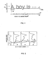
- FIG. 1 is a diagram showing an array of sensor elements in relation to a portion of a printed line to be scanned;
- FIG. 2 is a series of histograms representing successive portions of the scanning of a printed line;
- FIG. 3 is a block diagram illustrating character recognition apparatus in accordance with this invention; and
- FIG. 4 illustrates part of the operation of the apparatus of FIG. 3.
- Referring to FIG. 1, a linear scanner array is shown schematically at 11 in relation to a portion of a line of print to be scanned.
Array 11 may be of any suitable type used for optical character recognition such as a Reticon C Series Solid State Line Scanner, manufactured by Reticon Corp., Mt. View, California. As is well known,scanner 11 includes a suitable number, such as 64, of separate light sensor elements arranged vertically of the line to be scanned. Each element in thearray 11 produces an output signal which is a measure of the amount of light reflected from the portion of the scanned document associated with that element. The output signals from the elements ofarray 11 are converted to signals indicating either a light or dark condition of the scanned area, and in the present description it will be assumed that signals from dark or printed areas i.e. character parts, of the scanned document will produce a binary "one" or black bit signal, while signals from light or background areas of the scanned document produce a binary "zero".Array 11 is arranged to perform a vertical scan which extends above and below the line to be scanned, as represented by lla.. - Certain ones of the sensor elements in
array 11, which can be varied as will become apparent, function as a baseline searching window. In FIG. 1, these elements are identified as llb and are located in part of the lower half ofarray 11. For instance, in an array containing 64 sensor elements, 6 of these elements can be used for the group lIb. FIG. 1 will be discussed further in connection with detail baseline detection. - The principles involved in performing a coarse baseline prediction are indicated in FIG. 2, which is a series of horizontal density histograms for a scanned line of characters, each
separate frame frame 2A,point 3A represents the predicted baseline elevation, point 3B represents the predicted baseline elevation forframe 2B, etc. Thepoints line 3E in frame 2D (mid-way between the heights ofpoints line 3E and theline connecting points - FIG. 3 illustrates a particular embodiment of the invention in the form of character recognition apparatus. The output from
scanner 11 is supplied to athreshold buffer 12 which converts the signals from the sensors inarray 11 to binary ones or zeroes corresponding to signals from dark or light areas of the scanned document, as discussed above, and temporarily stores them. Thebuffer 12 provides an input to a horizontalprojection histogram generator 13, which is capable of appropriately counting the signals frombuffer 12 and generating signals corresponding to the histograms of FIG. 2 indicative of the location of the peak value in each segment of the line of characters.Generator 13 may also indicate the location of the peak value for the entire scanned line. The output fromgenerator 13 is supplied as the input to a baseline prediction and skewmeasurement network 14 which utilizes the signal fromgenerator 13 to produce predicted values for the baseline location and a measure of the skew of the predicted baseline, as shown in FIG. 2. The output fromnetwork 14 is supplied as an input to acharacter recognition processor 16 which may utilize this information in various ways. For example if the predicted baseline skew measurement exceeds, a predetermined value, the operation of the apparatus can be halted, automatically, or manually in response to a warning signal, to allow repositioning of the line of characters being sensed e.g. by repositioning the document being sensed. - Detailed baseline detection maybe understood by reference to FIGS. 1, 3 and 4. The output from
network 14 is also supplied to predictedbaseline position generator 17, which generates a predicted baseline position signal representing, for example, theline 18 in FIG. 1. This last signal controls a searchwindow selection circuit 31 which in effect determines which group of the sensor elements ofarray 11 shall be the search window for a particular line scan. For the first line of a document, after the search window has been determined as aforesaid, thebuffer 12 is re-read and re-supplies its signals, in respect of that same first line, to enable detection of the lowest black bit position occurring in the search window per vertical line scan byarray 11 as will be explained. The search window for the next line is determined to correspond to the predicted baseline position signal for the first line, it being assumed that thearray 11 relatively moves a standard line spacing between lines. This search window determination is available when said next line is scanned, so that the need to re-readbuffer 12 for this line or subsequent lines, is avoided. - As an alternative for the first line of a document, the
array 11 can be manually positioned to visually align the midpoint of a predetermined group of sensor elements approximately with the baseline of that first line, and searchwindow selection circuit 31 can produce an output corresponding to the selection of that predetermined group of sensor elements as the search window. During the first line scan, the predicted baseline position for the next line is determined as explained above, using the coarse baseline prediction technique, which determines the search window for the next line. Again, after thearray 11 has scanned one line, it is moved relatively to the document one standard line spacing. - As regards detecting the lowest black bit position occurring in the search window per vertical line scan by
array 11, the effect of the search window can be appreciated from Fig. 1. For the printed line shown in FIG. 1, which begins with "A Boy is ...", the lowest black dot position occurring in the search window llb for each vertical scan is shown immediately below. In this connection, it will be seen in FIG. 1 that the lower portion of the letter "y" in "boy" extends substantially below the predictedbaseline 18, and if a search window was not used, would produce low black bit positions considerably below those of the surrounding letters. However, only the low black bit positions associated with the letter "y" which are within searching window llb are detected so that theline 18a representing these low black bit positions corresponds generally to the overall bottom positions of each letter on.the line. - 'In general terms, the line of characters may include characters of the same height which do not extend below the baseline, characters of different height, characters extending below the baseline, characters with subscripts, or underlined characters, The lowest character parts of the character portions occurring in a narrow band extending along the line of characters and including the baseline are determined from the outputs of certain ones i.e. the search window, of the sensor elements. Characters which extend below the baseline, or subscripts of characters, and which are wholly or partly intersected by the band, provide apparent lowest character parts at the bottom edge of the band, or actual lowest character parts within the band.
- Circuitry for detecting the lowest black bit position is shown in FIG. 3 and includes a
shift register 26 which receives the digitized scanner output signals frombuffer 12.Shift register 26 operates to shift the bits in the buffer output by one position and to supply the shifted bits as one input B to an exclusive ORgate 27.Gate 27 receives the output ofbuffer 12 as another input A. - The output of
gate 27 is supplied as one input C to an ANDgate 28,gate 28 also receiving the input A frombuffer 12. The output ofgate 28 is supplied as an input D to an ANDgate 29 which receives an input E from searchwindow selection circuitry 31.Circuitry 31 is controlled by the indication of predicted baseline position frombox 17 and operates to opengate 29 during the period of each vertical scan when those signals of output A associated with the sensor elements inarray 11 functioning as the search window are being received bygate 29. The output F ofgate 29 is a succession of lowest black bit positions occurring in the searching window, for the successive vertical scans, and these are supplied to an averagingcircuit 32 which operates to average the lowest black bit position information for each scanned line or portion thereof to provide a determination of baseline position toOCR processor 16. By averaging for successive portions of the line, the skew of the baseline can be obtained as previously explained. Segmentation and recognition of character images takes place in theOCR processor 16 in response to the determined baseline position, and to the sensor element outputs represented by the signals A transmitted frombuffer 12 to processor 16 (by a line not shown in FIG. 3). - The operation of the detail baseline detection and its ability to separate underlinings from associated characters is shown in FIG. 4 in relation to scanning the line shown in FIG. 1. In FIG. 4,
reference 36 identifies the lower left leg of the letter "A" in "A Boy is ..." shown in FIG. 1, and 37 identifies the underscoring which is under the "A" in this line. The positions of the sensor elements inarray 11 are represented by the numbers 1-64 in the left hand column, only sensors 1-10 and 64 being shown to reduce the size of the figure. The outputs representing the signals A-F of FIG. 3 are shown in correspondingly labelled columns of FIG. 4. - The representational position of baseline searching window llb is shown in FIG. 4 and it can be seen that this window corresponds to the positions of sensor elements 5-10 in
array 11. The signals in.the different columns A-F correspond to their values whenscanner array 11 is at the position represented by line lla in FIG. 4. In column A it will be seen that black bits are produced bysensor elements sensor elements 2 and 3, representing the underscoring 37 beneathleg 36. The signals of column A are supplied to shiftregister 26 of FIG. 3 which operates to shift the signals left or up one position, as shown by the arrows. - The signals represented by column B are supplied to exclusive OR
gate 27 along with the signals A frombuffer 12. The'output ofgate 27 is represented by column C.in FIG. 4, containing bits insensor element positions gate 28 along with signal A frombuffer 12 to produce the signals shown in column D, having bits atpositions - Signals D are supplied to AND
gate 29 along with signals E from searchwindow selection circuitry 31. Since the baseline searching window in this example is assumed to extend across sensor elements 5-10,circuitry 31 generates bits in positions 5-10 as shown in column E. The output F fromgate 29 contains a single bit atsensor position 6 and it will be seen that this corresponds to the location of the bottom ofleg 36 and hence represents the true baseline forleg 36 and letter "A". - From FIG. 4, the apparatus can be regarded as operating to detect and locate the transition 36a from black to white (taking a downward scan) on the lower portion of
leg 36 and to disregard thetransition 36b from white to dark on the upper portion ofleg 36. By establishing the alignment and width of the baseline search window to exclude underscoring 37, a more accurate baseline is detected rather than obtaining an indication that underscoring 37 represented the location of the baseline at scan line lla. Since the apparatus distinguishes between the character and its associated underscoring, the apparatus can present the character itself to the recognition processor for recognition with or without the associated underscoring. - Various alternatives and modifications can be made to the above apparatus and its operation. For example the coarse baseline prediction involving determining one or more frequency distributions or histograms is not necessary, e.g. particularly with a line of characters which is continuously underlined. Thus the
scanner 11 can be manually positioned for the first line of characters corresponding to a predetermined search window for that first line, as already indicatpd. The search window for the next line will then be determined by controlling the searchwindow selection circuit 31 according to a detail baseline elevation measure obtained from averagingcircuits 32, it being assumed thatscanner 11 is moved relatively one standard line spacing from the line of characters to the next line. - Other possibilities exist for the averaging
circuits 32. For example a line fitting technique can be used to obtain the baseline from the succession of determined lowest character parts.
Claims (8)
Applications Claiming Priority (2)
| Application Number | Priority Date | Filing Date | Title |
|---|---|---|---|
| US25436 | 1979-03-30 | ||
| US06/025,436 US4251799A (en) | 1979-03-30 | 1979-03-30 | Optical character recognition using baseline information |
Publications (2)
| Publication Number | Publication Date |
|---|---|
| EP0017090A1 true EP0017090A1 (en) | 1980-10-15 |
| EP0017090B1 EP0017090B1 (en) | 1983-01-26 |
Family
ID=21826057
Family Applications (1)
| Application Number | Title | Priority Date | Filing Date |
|---|---|---|---|
| EP80101459A Expired EP0017090B1 (en) | 1979-03-30 | 1980-03-20 | Method and apparatus for sensing a line of characters, and character recognition apparatus |
Country Status (5)
| Country | Link |
|---|---|
| US (1) | US4251799A (en) |
| EP (1) | EP0017090B1 (en) |
| JP (1) | JPS55131875A (en) |
| CA (1) | CA1136766A (en) |
| DE (1) | DE3061728D1 (en) |
Cited By (7)
| Publication number | Priority date | Publication date | Assignee | Title |
|---|---|---|---|---|
| EP0043069A1 (en) * | 1980-07-02 | 1982-01-06 | International Business Machines Corporation | Segmentation apparatus and method for character recognition |
| WO1989005495A1 (en) * | 1987-12-02 | 1989-06-15 | Eastman Kodak Company | Skew detector for digital image processing system |
| EP0332471A2 (en) * | 1988-03-11 | 1989-09-13 | Kabushiki Kaisha Toshiba | Character recognition apparatus |
| EP0702329A3 (en) * | 1994-09-16 | 1997-02-26 | Compaq Computer Corp | Method and apparatus for determining positional guidelines of handwritten data |
| EP0712088A3 (en) * | 1994-11-10 | 1998-01-07 | Canon Kabushiki Kaisha | Page analysis system |
| EP2093994A1 (en) * | 2008-02-19 | 2009-08-26 | Canon Kabushiki Kaisha | Electronic document producing device, electronic document producing method and storage medium |
| US20230049395A1 (en) * | 2020-01-16 | 2023-02-16 | Visa International Service Association | System and Computer-Implemented Method for Character Recognition in Payment Card |
Families Citing this family (39)
| Publication number | Priority date | Publication date | Assignee | Title |
|---|---|---|---|---|
| US4379282A (en) * | 1979-06-01 | 1983-04-05 | Dest Corporation | Apparatus and method for separation of optical character recognition data |
| US4292622A (en) * | 1980-02-21 | 1981-09-29 | Hendrix Electronics, Inc. | System and method for processing horizontal line characteristics in an image |
| JPS6043555B2 (en) * | 1980-02-26 | 1985-09-28 | 株式会社トキメック | Printed character cutting device |
| JPS57141779A (en) * | 1981-02-26 | 1982-09-02 | Nec Corp | Character cutout system |
| DE3107521A1 (en) * | 1981-02-27 | 1982-09-16 | Siemens AG, 1000 Berlin und 8000 München | METHOD FOR AUTOMATICALLY DETECTING IMAGE AND TEXT OR GRAPHIC AREAS ON PRINT ORIGINALS |
| JPS5872275A (en) * | 1981-10-26 | 1983-04-30 | Nippon Telegr & Teleph Corp <Ntt> | Compensating device for document inclination |
| JPS5880779A (en) * | 1981-11-05 | 1983-05-14 | Toshiba Corp | Character reader |
| US5297222A (en) * | 1982-05-04 | 1994-03-22 | Hitachi, Ltd. | Image processing apparatus |
| US4741045A (en) * | 1983-09-23 | 1988-04-26 | Dest Corporation | Optical character isolation system, apparatus and method |
| US4783827A (en) * | 1985-05-27 | 1988-11-08 | Fuji Electric Co., Ltd. | Serial data processing apparatus |
| US4817166A (en) * | 1986-05-05 | 1989-03-28 | Perceptics Corporation | Apparatus for reading a license plate |
| US5081685A (en) * | 1988-11-29 | 1992-01-14 | Westinghouse Electric Corp. | Apparatus and method for reading a license plate |
| US5119441A (en) * | 1989-03-28 | 1992-06-02 | Ricoh Company, Ltd. | Optical character recognition apparatus and method using masks operation |
| US5077809A (en) * | 1989-05-30 | 1991-12-31 | Farshad Ghazizadeh | Optical character recognition |
| US5537483A (en) * | 1989-10-03 | 1996-07-16 | Staplevision, Inc. | Automated quality assurance image processing system |
| US5048096A (en) * | 1989-12-01 | 1991-09-10 | Eastman Kodak Company | Bi-tonal image non-text matter removal with run length and connected component analysis |
| US5245676A (en) * | 1989-12-21 | 1993-09-14 | Xerox Corporation | Determination of image skew angle from data including data in compressed form |
| JP2554187B2 (en) * | 1990-04-27 | 1996-11-13 | シャープ株式会社 | Basic line extraction method |
| US5077811A (en) * | 1990-10-10 | 1991-12-31 | Fuji Xerox Co., Ltd. | Character and picture image data processing system |
| JPH0592646A (en) * | 1991-09-30 | 1993-04-16 | Ezel Inc | Method for inspecting printed matter |
| US5276742A (en) * | 1991-11-19 | 1994-01-04 | Xerox Corporation | Rapid detection of page orientation |
| JP3320759B2 (en) * | 1991-12-26 | 2002-09-03 | 株式会社東芝 | Document image inclination detecting apparatus and method |
| DE4318526C2 (en) * | 1992-06-10 | 1999-11-25 | Canon Kk | Image input device |
| JPH08221576A (en) * | 1994-12-12 | 1996-08-30 | Toshiba Corp | Straight line detecting and eliminating system and destination area discriminating device for character string |
| JP4114959B2 (en) * | 1995-06-20 | 2008-07-09 | キヤノン株式会社 | Image processing method and apparatus |
| US6282324B1 (en) * | 1995-08-31 | 2001-08-28 | Northrop Grumman Corporation | Text image deblurring by high-probability word selection |
| JP4323606B2 (en) * | 1999-03-01 | 2009-09-02 | 理想科学工業株式会社 | Document image tilt detection device |
| JP5465819B2 (en) | 2000-02-12 | 2014-04-09 | アドビ システムズ, インコーポレイテッド | Text grid creation tool |
| US7305617B2 (en) * | 2000-02-12 | 2007-12-04 | Adobe Systems Incorporated | Method for aligning text to baseline grids and to CJK character grids |
| US20040205568A1 (en) * | 2002-03-01 | 2004-10-14 | Breuel Thomas M. | Method and system for document image layout deconstruction and redisplay system |
| JP4189654B2 (en) * | 2003-04-18 | 2008-12-03 | セイコーエプソン株式会社 | Image processing device |
| US7606408B2 (en) * | 2004-06-21 | 2009-10-20 | Seiko Epson Corporation | Magnetic ink character reading method and program |
| JP5322517B2 (en) * | 2008-07-08 | 2013-10-23 | キヤノン株式会社 | Image processing apparatus and method |
| US9275022B2 (en) * | 2013-07-31 | 2016-03-01 | Google Inc. | Mechanism for setting ascent and baseline for HTML elements |
| US20170004410A1 (en) * | 2015-07-03 | 2017-01-05 | Christopher William Paran | Standardized process to quantify the value of research manuscripts |
| US10192127B1 (en) | 2017-07-24 | 2019-01-29 | Bank Of America Corporation | System for dynamic optical character recognition tuning |
| US10346702B2 (en) | 2017-07-24 | 2019-07-09 | Bank Of America Corporation | Image data capture and conversion |
| US10803242B2 (en) | 2018-10-26 | 2020-10-13 | International Business Machines Corporation | Correction of misspellings in QA system |
| US11238618B2 (en) | 2019-11-26 | 2022-02-01 | International Business Machines Corporation | Image recognition |
Citations (5)
| Publication number | Priority date | Publication date | Assignee | Title |
|---|---|---|---|---|
| US3509415A (en) * | 1969-01-13 | 1970-04-28 | Ibm | Format scheme for vidicon scanners |
| US3587047A (en) * | 1968-01-03 | 1971-06-22 | Ibm | Selective character centering line follow logics |
| US3921136A (en) * | 1972-01-21 | 1975-11-18 | Bar Lev Hillel | Automatic pattern recognition method and apparatus particularly for optically recognizing characters |
| US4013999A (en) * | 1974-08-15 | 1977-03-22 | Recognition Equipment Incorporated | Single read station acquisition for character recognition |
| US4083034A (en) * | 1976-10-04 | 1978-04-04 | Recognition Equipment Incorporated | Plural tracker character detection and boundary location system |
Family Cites Families (11)
| Publication number | Priority date | Publication date | Assignee | Title |
|---|---|---|---|---|
| GB981431A (en) * | 1960-05-20 | 1965-01-27 | Nat Res Dev | Improvements in or relating to character recognition systems and arrangements |
| US3142761A (en) * | 1960-11-30 | 1964-07-28 | Control Data Corp | Photosensitive line following servo system for reading machines |
| US3221302A (en) * | 1961-05-15 | 1965-11-30 | Rca Corp | Transducer position control apparatus |
| US3231860A (en) * | 1962-01-15 | 1966-01-25 | Philco Corp | Character position detection and correction system |
| US3350505A (en) * | 1964-02-18 | 1967-10-31 | Ibm | Scanning apparatus employing means compensating for variations in character height and width and for variations in the position or linearity of lines of print |
| US3295105A (en) * | 1964-08-27 | 1966-12-27 | Sylvania Electric Prod | Scan control and normalization for a character recognition system |
| US3506807A (en) * | 1965-11-24 | 1970-04-14 | Ibm | Scan centering device |
| FR1582971A (en) * | 1967-09-02 | 1969-10-10 | ||
| NL7009520A (en) * | 1970-06-27 | 1971-12-29 | ||
| US3852573A (en) * | 1973-11-16 | 1974-12-03 | Scanner | Alignment correction for read scan raster fields |
| US4028674A (en) * | 1976-06-04 | 1977-06-07 | Recognition Equipment Incorporated | Automated signature verification system |
-
1979
- 1979-03-30 US US06/025,436 patent/US4251799A/en not_active Expired - Lifetime
-
1980
- 1980-01-14 CA CA000343631A patent/CA1136766A/en not_active Expired
- 1980-02-05 JP JP1213380A patent/JPS55131875A/en active Granted
- 1980-03-20 EP EP80101459A patent/EP0017090B1/en not_active Expired
- 1980-03-20 DE DE8080101459T patent/DE3061728D1/en not_active Expired
Patent Citations (5)
| Publication number | Priority date | Publication date | Assignee | Title |
|---|---|---|---|---|
| US3587047A (en) * | 1968-01-03 | 1971-06-22 | Ibm | Selective character centering line follow logics |
| US3509415A (en) * | 1969-01-13 | 1970-04-28 | Ibm | Format scheme for vidicon scanners |
| US3921136A (en) * | 1972-01-21 | 1975-11-18 | Bar Lev Hillel | Automatic pattern recognition method and apparatus particularly for optically recognizing characters |
| US4013999A (en) * | 1974-08-15 | 1977-03-22 | Recognition Equipment Incorporated | Single read station acquisition for character recognition |
| US4083034A (en) * | 1976-10-04 | 1978-04-04 | Recognition Equipment Incorporated | Plural tracker character detection and boundary location system |
Non-Patent Citations (3)
| Title |
|---|
| IBM TECHNICAL DISCLOSURE BULLETIN, Vol. 13, Nr. 2, July 1970 Armonk (US) J.E. CARRINGTON et al.: "Line finding by profile analysis", pages 351-352 * Page 351, paragraph 2 to page 352, paragraph 1; figure * * |
| PROCEEDINGS I.R.E.E. AUSTRALIA, October 1970 Canberra (US) J. WILSON: "The recognition of handwritten words using a linefollower", pages 339-344 * Page 342; column 2; paragraph 2 to page 343, column 1, paragraph 1 * * |
| THE MARCONI REVIEW, Vol. 32, No. 172, 1969, Gret Baddow (GB) B. HAMMANS: "The design of a page scanner for character recognition", pages 31-48 * Page 35, paragraph 3 to page 36, paragraph 4; figures 3, 4; page 42 * * |
Cited By (10)
| Publication number | Priority date | Publication date | Assignee | Title |
|---|---|---|---|---|
| EP0043069A1 (en) * | 1980-07-02 | 1982-01-06 | International Business Machines Corporation | Segmentation apparatus and method for character recognition |
| WO1989005495A1 (en) * | 1987-12-02 | 1989-06-15 | Eastman Kodak Company | Skew detector for digital image processing system |
| EP0332471A2 (en) * | 1988-03-11 | 1989-09-13 | Kabushiki Kaisha Toshiba | Character recognition apparatus |
| EP0332471A3 (en) * | 1988-03-11 | 1992-05-20 | Kabushiki Kaisha Toshiba | Character recognition apparatus |
| EP0702329A3 (en) * | 1994-09-16 | 1997-02-26 | Compaq Computer Corp | Method and apparatus for determining positional guidelines of handwritten data |
| EP0712088A3 (en) * | 1994-11-10 | 1998-01-07 | Canon Kabushiki Kaisha | Page analysis system |
| US5987171A (en) * | 1994-11-10 | 1999-11-16 | Canon Kabushiki Kaisha | Page analysis system |
| EP2093994A1 (en) * | 2008-02-19 | 2009-08-26 | Canon Kabushiki Kaisha | Electronic document producing device, electronic document producing method and storage medium |
| US8532386B2 (en) | 2008-02-19 | 2013-09-10 | Canon Kabushiki Kaisha | Electronic document producing device, electronic document producing method and storage medium |
| US20230049395A1 (en) * | 2020-01-16 | 2023-02-16 | Visa International Service Association | System and Computer-Implemented Method for Character Recognition in Payment Card |
Also Published As
| Publication number | Publication date |
|---|---|
| US4251799A (en) | 1981-02-17 |
| CA1136766A (en) | 1982-11-30 |
| JPS55131875A (en) | 1980-10-14 |
| EP0017090B1 (en) | 1983-01-26 |
| DE3061728D1 (en) | 1983-03-03 |
| JPS61675B2 (en) | 1986-01-10 |
Similar Documents
| Publication | Publication Date | Title |
|---|---|---|
| EP0017090B1 (en) | Method and apparatus for sensing a line of characters, and character recognition apparatus | |
| US4449052A (en) | Method of printing and detecting optimum bar code test patterns | |
| US4204193A (en) | Adaptive alignment for pattern recognition system | |
| US5444797A (en) | Method and apparatus for automatic character script determination | |
| US4897880A (en) | Data acquisition control method and system for a hand held reader | |
| US5081690A (en) | Row-by-row segmentation and thresholding for optical character recognition | |
| US5164996A (en) | Optical character recognition by detecting geo features | |
| US4891750A (en) | Optical character recognition by forming and detecting matrices of geo features | |
| US11823497B2 (en) | Image processing system and an image processing method | |
| EP1033864B1 (en) | Document-inclination detector | |
| JP4011646B2 (en) | Line detection method and character recognition device | |
| EP0062665A1 (en) | Segmentation system and method for optical character scanning | |
| US5369715A (en) | Optical character recognition system | |
| Kapoor et al. | Skew angle detectionof a cursive handwritten Devanagari script character image. | |
| AU613013B2 (en) | Data acquisition control method and system for a hand held reader | |
| EP0476873B1 (en) | Method of and apparatus for separating image regions | |
| JP2716291B2 (en) | Paper information input device | |
| JP2581809B2 (en) | Character extraction device | |
| JP3236898B2 (en) | Image processing apparatus and processing method thereof | |
| JPH07160810A (en) | Character recognizing device | |
| JP2715930B2 (en) | Line detection method | |
| JPH0782524B2 (en) | Optical character reader | |
| JPS63208990A (en) | Character pattern segmenting device | |
| JP4057121B2 (en) | Image recognition device | |
| JPH0632074B2 (en) | Normalization method |
Legal Events
| Date | Code | Title | Description |
|---|---|---|---|
| PUAI | Public reference made under article 153(3) epc to a published international application that has entered the european phase |
Free format text: ORIGINAL CODE: 0009012 |
|
| AK | Designated contracting states |
Designated state(s): DE FR GB IT |
|
| 17P | Request for examination filed |
Effective date: 19801023 |
|
| GRAA | (expected) grant |
Free format text: ORIGINAL CODE: 0009210 |
|
| AK | Designated contracting states |
Designated state(s): DE FR GB IT |
|
| PG25 | Lapsed in a contracting state [announced via postgrant information from national office to epo] |
Ref country code: IT Free format text: LAPSE BECAUSE OF FAILURE TO SUBMIT A TRANSLATION OF THE DESCRIPTION OR TO PAY THE FEE WITHIN THE PRESCRIBED TIME-LIMIT;WARNING: LAPSES OF ITALIAN PATENTS WITH EFFECTIVE DATE BEFORE 2007 MAY HAVE OCCURRED AT ANY TIME BEFORE 2007. THE CORRECT EFFECTIVE DATE MAY BE DIFFERENT FROM THE ONE RECORDED. Effective date: 19830126 |
|
| REF | Corresponds to: |
Ref document number: 3061728 Country of ref document: DE Date of ref document: 19830303 |
|
| ET | Fr: translation filed | ||
| KL | Correction list |
Free format text: 83/02 ZEICHNUNG |
|
| PGFP | Annual fee paid to national office [announced via postgrant information from national office to epo] |
Ref country code: GB Payment date: 19900228 Year of fee payment: 11 |
|
| PG25 | Lapsed in a contracting state [announced via postgrant information from national office to epo] |
Ref country code: GB Effective date: 19910320 |
|
| GBPC | Gb: european patent ceased through non-payment of renewal fee | ||
| PGFP | Annual fee paid to national office [announced via postgrant information from national office to epo] |
Ref country code: FR Payment date: 19950228 Year of fee payment: 16 |
|
| PGFP | Annual fee paid to national office [announced via postgrant information from national office to epo] |
Ref country code: DE Payment date: 19950330 Year of fee payment: 16 |
|
| PG25 | Lapsed in a contracting state [announced via postgrant information from national office to epo] |
Ref country code: FR Effective date: 19961129 |
|
| PG25 | Lapsed in a contracting state [announced via postgrant information from national office to epo] |
Ref country code: DE Effective date: 19961203 |
|
| REG | Reference to a national code |
Ref country code: FR Ref legal event code: ST |
|
| PLBE | No opposition filed within time limit |
Free format text: ORIGINAL CODE: 0009261 |
|
| STAA | Information on the status of an ep patent application or granted ep patent |
Free format text: STATUS: NO OPPOSITION FILED WITHIN TIME LIMIT |