EP0020111A2 - Arrangement comprising a cryogenic refrigerator and an insulated enclosure, and an assembly including such an arrangement - Google Patents
Arrangement comprising a cryogenic refrigerator and an insulated enclosure, and an assembly including such an arrangement Download PDFInfo
- Publication number
- EP0020111A2 EP0020111A2 EP80301721A EP80301721A EP0020111A2 EP 0020111 A2 EP0020111 A2 EP 0020111A2 EP 80301721 A EP80301721 A EP 80301721A EP 80301721 A EP80301721 A EP 80301721A EP 0020111 A2 EP0020111 A2 EP 0020111A2
- Authority
- EP
- European Patent Office
- Prior art keywords
- orifice
- cryogenic refrigerator
- variable orifice
- arrangement
- variable
- Prior art date
- Legal status (The legal status is an assumption and is not a legal conclusion. Google has not performed a legal analysis and makes no representation as to the accuracy of the status listed.)
- Granted
Links
- 238000012544 monitoring process Methods 0.000 claims description 2
- 238000005057 refrigeration Methods 0.000 abstract description 6
- IJGRMHOSHXDMSA-UHFFFAOYSA-N Atomic nitrogen Chemical compound N#N IJGRMHOSHXDMSA-UHFFFAOYSA-N 0.000 description 10
- 239000007789 gas Substances 0.000 description 10
- 239000007788 liquid Substances 0.000 description 6
- 239000012530 fluid Substances 0.000 description 5
- 229910052757 nitrogen Inorganic materials 0.000 description 5
- 239000002245 particle Substances 0.000 description 3
- 230000000694 effects Effects 0.000 description 2
- 238000013019 agitation Methods 0.000 description 1
- 238000013459 approach Methods 0.000 description 1
- 238000001816 cooling Methods 0.000 description 1
- 230000009977 dual effect Effects 0.000 description 1
- 230000002708 enhancing effect Effects 0.000 description 1
- 230000002028 premature Effects 0.000 description 1
- 230000035939 shock Effects 0.000 description 1
- 239000013589 supplement Substances 0.000 description 1
- 238000009966 trimming Methods 0.000 description 1
Images

Classifications
-
- F—MECHANICAL ENGINEERING; LIGHTING; HEATING; WEAPONS; BLASTING
- F25—REFRIGERATION OR COOLING; COMBINED HEATING AND REFRIGERATION SYSTEMS; HEAT PUMP SYSTEMS; MANUFACTURE OR STORAGE OF ICE; LIQUEFACTION SOLIDIFICATION OF GASES
- F25J—LIQUEFACTION, SOLIDIFICATION OR SEPARATION OF GASES OR GASEOUS OR LIQUEFIED GASEOUS MIXTURES BY PRESSURE AND COLD TREATMENT OR BY BRINGING THEM INTO THE SUPERCRITICAL STATE
- F25J1/00—Processes or apparatus for liquefying or solidifying gases or gaseous mixtures
- F25J1/02—Processes or apparatus for liquefying or solidifying gases or gaseous mixtures requiring the use of refrigeration, e.g. of helium or hydrogen ; Details and kind of the refrigeration system used; Integration with other units or processes; Controlling aspects of the process
- F25J1/0243—Start-up or control of the process; Details of the apparatus used; Details of the refrigerant compression system used
- F25J1/0257—Construction and layout of liquefaction equipments, e.g. valves, machines
- F25J1/0275—Construction and layout of liquefaction equipments, e.g. valves, machines adapted for special use of the liquefaction unit, e.g. portable or transportable devices
- F25J1/0276—Laboratory or other miniature devices
-
- F—MECHANICAL ENGINEERING; LIGHTING; HEATING; WEAPONS; BLASTING
- F25—REFRIGERATION OR COOLING; COMBINED HEATING AND REFRIGERATION SYSTEMS; HEAT PUMP SYSTEMS; MANUFACTURE OR STORAGE OF ICE; LIQUEFACTION SOLIDIFICATION OF GASES
- F25B—REFRIGERATION MACHINES, PLANTS OR SYSTEMS; COMBINED HEATING AND REFRIGERATION SYSTEMS; HEAT PUMP SYSTEMS
- F25B9/00—Compression machines, plants or systems, in which the refrigerant is air or other gas of low boiling point
- F25B9/02—Compression machines, plants or systems, in which the refrigerant is air or other gas of low boiling point using Joule-Thompson effect; using vortex effect
-
- F—MECHANICAL ENGINEERING; LIGHTING; HEATING; WEAPONS; BLASTING
- F25—REFRIGERATION OR COOLING; COMBINED HEATING AND REFRIGERATION SYSTEMS; HEAT PUMP SYSTEMS; MANUFACTURE OR STORAGE OF ICE; LIQUEFACTION SOLIDIFICATION OF GASES
- F25B—REFRIGERATION MACHINES, PLANTS OR SYSTEMS; COMBINED HEATING AND REFRIGERATION SYSTEMS; HEAT PUMP SYSTEMS
- F25B2309/00—Gas cycle refrigeration machines
- F25B2309/02—Gas cycle refrigeration machines using the Joule-Thompson effect
- F25B2309/022—Gas cycle refrigeration machines using the Joule-Thompson effect characterised by the expansion element
-
- F—MECHANICAL ENGINEERING; LIGHTING; HEATING; WEAPONS; BLASTING
- F25—REFRIGERATION OR COOLING; COMBINED HEATING AND REFRIGERATION SYSTEMS; HEAT PUMP SYSTEMS; MANUFACTURE OR STORAGE OF ICE; LIQUEFACTION SOLIDIFICATION OF GASES
- F25J—LIQUEFACTION, SOLIDIFICATION OR SEPARATION OF GASES OR GASEOUS OR LIQUEFIED GASEOUS MIXTURES BY PRESSURE AND COLD TREATMENT OR BY BRINGING THEM INTO THE SUPERCRITICAL STATE
- F25J2290/00—Other details not covered by groups F25J2200/00 - F25J2280/00
- F25J2290/42—Modularity, pre-fabrication of modules, assembling and erection, horizontal layout, i.e. plot plan, and vertical arrangement of parts of the cryogenic unit, e.g. of the cold box
Definitions
- This invention relates to cryogenic refrigerators, to an arrangement incorporating such cryogenic refrigerators and to a system incorporating such cryogenic refrigerators.
- Cryogenic refrigerators are used to produce cryogenic liquid by the expansion of a compressed fluid, for example nitrogen, through one or more orifices. They are commonly used for cooling infra red detectors and in such applications are usually mounted in a vacuum insulated dewar.
- the infra red detector is mounted in the vacuum space at the bottom the the dewar in thermal contact with the inner wall of the dewar and is cooled by conduction from the cryogenic liquid as it collects in the bottom of the dewar.
- Infra red detectors are used in a variety of civil and military applications and form an esstential part of the guidance systems of heat seeking missiles. In this latter case it is essential that the infra red detectors can be brought to operational temperature (about 77°K) as quickly as possible and maintained at operational temperature for a reasonable duration. Thus, it should be possible to bring the infra red detector of a small heat seeking missile forming part of the armament of a plane to operational temperature within a minute of pushing the button to arm the missile. The infra red detector should then be capable of remaining operational throughout the duration of at least one flight and preferably several.
- One cryogenic refrigerator which has been proposed for this purpose uses a fixed orifice and a variable orifice.
- the fixed orifice is calibrated so that without the variable orifice it will maintain the infra red detector at its upper acceptable temperature (about 82°K).
- the variable orifice is continuously opening and closing to maintain the temperature at about 77 ⁇ 3 0 K.
- the compressed nitrogen supplied to the cryogenic refrigerator often contains minute particles which originate from the cylinder in which it is kept. These particles can become lodged in the variable orifice which can result in either the variable orifice not closing and premature exhaustion of the compressed nitrogen or the variable orifice becoming substantially blocked with the result that the temperature in the cryogenic refrigerator increases to about 81°K which is above the optimum temperature for the infra red detector.
- the variable orifice when the variable orifice is closed the flow through the fixed orifice causes only gentle movement of the cryogenic liquid which provides a lower heat transfer rate to the infra red detector than if the cryogenic liquid were to be more vigorously agitated.
- cryogenic refrigerator which has a variable orifice and a fixed orifice but which differs from the prior art in that the fixed orifice is sized to maintain the infra red detector at its desired operating temperature (about 77 0 K) and the variable orifice opens only for initial cool down and when the temperature of the infra red detector reaches for example 82°K, which will occur when the pressure of the compressed fluid has dropped sufficiently.
- the present cryogenic refrigerator can readily be distinguished from the prior art cryogenic refrigerator in that in the present case if the cryogenic refrigerator is operated in an insulated enclosure the temperature will fall after the variable orifice has closed whilst in the prior art the temperature will rise after the variable orifice closes.
- the present invention provides a cryogenic refrigerator having a variable orifice and a fixed orifice characterized in that when said cryogenic refrigerator is operated in an insulated enclosure the temperature in said enclosure will fall after said variable orifice has closed.
- variable orifice only closes once as the cryogenic refrigerator approaches operational temperature and the probability of becoming blocked is considerably less than in the case of the continuously moving variable orifice.
- the relatively higher flow through the fixed orifice causes relatively greater agitation of the liquid in the bottom of the dewar thereby enhancing heat transfer to the infra red detector.
- cryogenic refrigerator For military use each cryogenic refrigerator is carefully designed so that the refrigeration produced is compatible with the refrigeration required. However, such cryogenic refrigerator can be used in other locations and in such cases it may be desirable to provide a control valve to admit or withhold compressed gas from the cryogenic refrigerator as desired. Suitable control valves could comprise a solenoid valve actuable by a temperature sensor or a vapour actuated valve.
- variable orifice and the fixed orifice will normally be defined by separate and distinct entities, however they can be defined by an arrangement comprising a single orifice, a needle valve movable towards and away from said single orifice, and a member for preventing said needle valve closing said single orifice or an arrangement comprising comprising a single orifice provided with at least one notch, and a needle valve movable towards and away from said single orifice to open and close said single orifice.
- variable orifice and the fixed orifice are separate and distinct entities
- variable orifice and the fixed orifice are preferably connected to the warm end of the cryogenic refrigerator by separate and distinct conduits.
- Cryogenic refrigerators may be used in conjunction with a temperature sensor for monitoring the temperature at or adjacent the cold end of said cryogenic refrigerator and a valve connected to said temperature sensor and operable, in use, to permit or prohibit compressed gas entering said cryogenic refrigerator in accordance with the signals received from said temperature sensor.
- the cryogenic refrigerator will be connected to a cylinder of compressed gas at a pressure X (usually nitrogen at 400 atmospheres).
- a pressure X usually nitrogen at 400 atmospheres.
- the cryogenic refrigerator is designed so that after initial cool down said variable orifice will not reopen at an ambient temperature of 20°C until the pressure in the cylinder falls to or below 0.5 X.
- a cryogenic refrigerator 10 which includes a mandrel 12 and a heat exchanger 14.
- the heat exchanger 14 includes a central conduit 16 upon which are disposed a plurality of fins.
- the heat exchanger 14 is wrapped around the mandrel and extends from warm end flange 28 to a variable orifice comprising an orifice 18 and a needle 20.
- the needle 20 is actuated by a bellows 13 disposed within mandrel 12 and similar to that shown in US Patent Specification No. 3,728,868. Projecting beyond the variable orifice is a length of small diameter tubing 22 which terminates in a fixed orifice 24.
- the length of small diameter tubing 22 is selected so that the fixed orifice 24 has a flow that is small relative to the flow through the variable orifice when the variable orifice is fully open but is greater than five percent (5%) of the maximum possible flow through the heat exchanger 14 at maximum initial source pressure and maximum ambient operating temperature.
- the flow through the fixed orifice can be adjusted by trimming the length of the small diameter tubing 22.
- the cryogenic refrigerator 10 includes a head 26 which is fixed to the warm end flange 28, a high pressure fluid hose adapter 32 and a filter 30 to filter out large particles of contaminents from the gas prior to entering the inlet section 34 of the heat exchanger 14.
- the cryogenic refrigerator utilizes the variable orifice only to provide a high flow for fast cool down of the cryogenic refrigerator 10.
- the variable orifice remains closed, the fixed orifice 24 being sized to provide adequate flow for all normal operating conditions until the source pressure drops to approximately one-half the initial pressure. At this time the variable orifice opens to supplement the refrigeration provided by the flow through the fixed orifice 24.
- a solenoid valve (not shown) is installed on the inlet line up-stream of high pressure flow hose adaptor 32.
- the high pressure working fluid is controlled by the solenoid valve when opens and closes in response to a temperature signal from a sensor at the cold end of the cryogenic refrigerator 10 or in the dewar into which the cryogenic refrigeratorl0 is placed.
- other control valves such as vapor bulb actuated valve can be used for control of fluid flow through the heat exchanger 14.
- Curve A represents the flow rate through the variable orifice of the embodiment shown in Figure 1 before the variable orifice closes.
- Curves B and C represent two possible fixed orifices that might be used in parallel with the variable orifice; and curve D shows the pressure versus flow characteristics of the fixed orifice of a combined variable and fixed orifice cryogenic refrigerator such as shown in US Patent 3,82.7,252.
- Curve C is used to illustate the operation of the embodiment shown in Figure 1. Assume an ambient temperature of 24°C and initial pressure of 300 atmospheres. The flow through the fixed orifice is sufficient to maintain the required cryogenic temperature until the pressure drops to 160 atmospheres. Thus the variable orifice remains closed until the pressure decays to 160 atmospheres (where curve C intersects the 24°C curve) at which time the flow through the fixed orifice is not adequate to keep the cryogenic refrigerator cold so that the variable orifice opens and provides the additional gas required to maintain the operating temperature. If the ambient temperature was 74°C the variable orifice would be supplying additional gas at all pressures below 300 atmospheres as shown by the intersection of the 74°C curve with the C curve. Similarly, at -51°C the variable orifice would not open until the pressure reaches 50 atmospheres as shown by the intersection of curve C and the -51°C curve.
- Nozzle B would be selected for an application where the ambient temperature is greater than 74°C or where geometry and heat load of the device to be cooled would upset the variable orifice control mechanism.
- Such a dual orifice cryogenic refrigerator would typically be used with an inlet solenoid valve actuated by a cold end temperature sensor such as described in relation to the cryogenic refrigerator of Figure 1.
- Use of the inlet solenoid valve permits average flow rates nearly equal to the ideal variable orifice cryogenic refrigerator to be achieved.
- variable orifice flow rate the variable orifice serves the primary function of providing fast cool down after which it closes and typically remains closed until the bottle pressure drops to a point to the left of the appropriate temperature curve.
- FIG. 2 shows a cryogenic refrigerator 52 mounted on a dewar 50 containing an infra red detector 51.
- the relative positions of the needle 53 and the orifice are shown with the cryogenic refrigerator warm.
- high pressure gas e.g. nitrogen at 400 atmospheres
- the cryogenic refrigerator cools down as a result of the Joule-Thompson effect.
- the needle would move to the orifice until the flow rate produced just enough refrigeration to satisfy the temperature equilibrium of the system.
- control motion range is limited by a shoulder 54 which prevents the bellows from pulling the needle 53 closer to the orifice and thus accomplishes the objective of having a fixed orifice in parallel with a variable orifice.
- the needle does not contact the orifice wear of the orifice and needle are minimal even with repeated usage.
- the needle and orifice are also protected from being damaged by mishandling of the units.
- FIG. 3 shows the fixed orifice 56 separate from the variable orifice 55. Normally there is insufficient relative movement between the needle and the orifice 55 on warm up to enable all but the smallest contaminents to be blown free in this type of arrangement.
- the apparatus of Figure 4 contains a variable orifice 57 and a fixed orifice.
- the fixed orifice is achieved by notching the variable orifice.
- the orifice is subject to wear.
- Figure 5 shows another embodiment in which two high pressure tubes 58 and 59 are employed with one terminating in a variable orifice and the other terminating in a fixed orifice.
- Figure 6 shows another embodiment of Figure 2 in which a second shoulder 62 is added to the sensing bulb that limits the maximum range of control motion. This is sometimes desirable because it permits the maximum flow rate to be set for a desired cool down rate.
- the two shoulders 62,64 also provide motion limits that permit the control mechanism to withstand very high shock loads as are found in certain military applications.
Abstract
Description
- This invention relates to cryogenic refrigerators, to an arrangement incorporating such cryogenic refrigerators and to a system incorporating such cryogenic refrigerators.
- Cryogenic refrigerators are used to produce cryogenic liquid by the expansion of a compressed fluid, for example nitrogen, through one or more orifices. They are commonly used for cooling infra red detectors and in such applications are usually mounted in a vacuum insulated dewar. The infra red detector is mounted in the vacuum space at the bottom the the dewar in thermal contact with the inner wall of the dewar and is cooled by conduction from the cryogenic liquid as it collects in the bottom of the dewar.
- Infra red detectors are used in a variety of civil and military applications and form an esstential part of the guidance systems of heat seeking missiles. In this latter case it is essential that the infra red detectors can be brought to operational temperature (about 77°K) as quickly as possible and maintained at operational temperature for a reasonable duration. Thus, it should be possible to bring the infra red detector of a small heat seeking missile forming part of the armament of a plane to operational temperature within a minute of pushing the button to arm the missile. The infra red detector should then be capable of remaining operational throughout the duration of at least one flight and preferably several.
- One cryogenic refrigerator which has been proposed for this purpose uses a fixed orifice and a variable orifice. The fixed orifice is calibrated so that without the variable orifice it will maintain the infra red detector at its upper acceptable temperature (about 82°K). The variable orifice is continuously opening and closing to maintain the temperature at about 77±30K.
- We have found that this type of cryogenic refrigerator has two disadvantages. Firstly, the compressed nitrogen supplied to the cryogenic refrigerator often contains minute particles which originate from the cylinder in which it is kept. These particles can become lodged in the variable orifice which can result in either the variable orifice not closing and premature exhaustion of the compressed nitrogen or the variable orifice becoming substantially blocked with the result that the temperature in the cryogenic refrigerator increases to about 81°K which is above the optimum temperature for the infra red detector. Secondly, when the variable orifice is closed the flow through the fixed orifice causes only gentle movement of the cryogenic liquid which provides a lower heat transfer rate to the infra red detector than if the cryogenic liquid were to be more vigorously agitated.
- In order to reduce the disadvantages outlined above we propose to use a cryogenic refrigerator which has a variable orifice and a fixed orifice but which differs from the prior art in that the fixed orifice is sized to maintain the infra red detector at its desired operating temperature (about 770K) and the variable orifice opens only for initial cool down and when the temperature of the infra red detector reaches for example 82°K, which will occur when the pressure of the compressed fluid has dropped sufficiently.
- The present cryogenic refrigerator can readily be distinguished from the prior art cryogenic refrigerator in that in the present case if the cryogenic refrigerator is operated in an insulated enclosure the temperature will fall after the variable orifice has closed whilst in the prior art the temperature will rise after the variable orifice closes.
- Whereas current infra red detectors operate most efficiently at 770K considerable effort is being made to develop an infra red detector which will operate at warmer temperatures. However, similar considerations will apply to the design of the cryogenic refrigerator and, in its broadest aspect, the present invention provides a cryogenic refrigerator having a variable orifice and a fixed orifice characterized in that when said cryogenic refrigerator is operated in an insulated enclosure the temperature in said enclosure will fall after said variable orifice has closed.
- As will be appreciated the variable orifice only closes once as the cryogenic refrigerator approaches operational temperature and the probability of becoming blocked is considerably less than in the case of the continuously moving variable orifice. In addition, when used in a dewar, the relatively higher flow through the fixed orifice causes relatively greater agitation of the liquid in the bottom of the dewar thereby enhancing heat transfer to the infra red detector.
- For military use each cryogenic refrigerator is carefully designed so that the refrigeration produced is compatible with the refrigeration required. However, such cryogenic refrigerator can be used in other locations and in such cases it may be desirable to provide a control valve to admit or withhold compressed gas from the cryogenic refrigerator as desired. Suitable control valves could comprise a solenoid valve actuable by a temperature sensor or a vapour actuated valve.
- The variable orifice and the fixed orifice will normally be defined by separate and distinct entities, however they can be defined by an arrangement comprising a single orifice, a needle valve movable towards and away from said single orifice, and a member for preventing said needle valve closing said single orifice or an arrangement comprising comprising a single orifice provided with at least one notch, and a needle valve movable towards and away from said single orifice to open and close said single orifice.
- Where the variable orifice and the fixed orifice are separate and distinct entities the variable orifice and the fixed orifice are preferably connected to the warm end of the cryogenic refrigerator by separate and distinct conduits.
- Cryogenic refrigerators according to the present invention may be used in conjunction with a temperature sensor for monitoring the temperature at or adjacent the cold end of said cryogenic refrigerator and a valve connected to said temperature sensor and operable, in use, to permit or prohibit compressed gas entering said cryogenic refrigerator in accordance with the signals received from said temperature sensor.
- In an operational system the cryogenic refrigerator will be connected to a cylinder of compressed gas at a pressure X (usually nitrogen at 400 atmospheres). Preferably, the cryogenic refrigerator is designed so that after initial cool down said variable orifice will not reopen at an ambient temperature of 20°C until the pressure in the cylinder falls to or below 0.5 X.
- For a better understanding of the present invention and to show how the same may be carried into effect, reference will now be made, by way of example, to the accompanying drawings, in which:
- Figure 1 is an elevational view, partially fragmentary, of a first embodiment of a cryogenic refrigerator according to the present invention;
- Figure 2 is a schematic presentation of the cold end of a second embodiment of a cryogenic refrigerator according to the present invention mounted in a vacuum insulated dewar;
- Figure 3 is a fragmentary view of the cold end of a third embodiment of a cryogenic refrigerator according to the present invention;
- Figure 4 is a fragmentary view of the cold end of a fourth embodiment of a cryogenic refrigerator according to the present invention;
- Figure 5 is a fragmentary view of the cold end of a fifth embodiment of a cryogenic refrigerator according to the present invention;
- Figure 6 is a fragmentary view of the cold end of a sixth embodiment of a cryogenic refrigerator according to the present invention; and
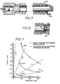
- Figure 7 is a plot of flow versus pressure for cryogenic refrigerator according to the prior art and the present invention.
- Referring to Figure 1 there is shown a
cryogenic refrigerator 10 which includes a mandrel 12 and a heat exchanger 14. The heat exchanger 14 includes acentral conduit 16 upon which are disposed a plurality of fins. The heat exchanger 14 is wrapped around the mandrel and extends fromwarm end flange 28 to a variable orifice comprising an orifice 18 and aneedle 20. Theneedle 20 is actuated by a bellows 13 disposed within mandrel 12 and similar to that shown in US Patent Specification No. 3,728,868. Projecting beyond the variable orifice is a length ofsmall diameter tubing 22 which terminates in afixed orifice 24. The length ofsmall diameter tubing 22 is selected so that thefixed orifice 24 has a flow that is small relative to the flow through the variable orifice when the variable orifice is fully open but is greater than five percent (5%) of the maximum possible flow through the heat exchanger 14 at maximum initial source pressure and maximum ambient operating temperature. As is well known in the art the flow through the fixed orifice can be adjusted by trimming the length of thesmall diameter tubing 22. - The
cryogenic refrigerator 10 includes ahead 26 which is fixed to thewarm end flange 28, a high pressurefluid hose adapter 32 and afilter 30 to filter out large particles of contaminents from the gas prior to entering the inlet section 34 of the heat exchanger 14. - In the embodiment shown in Figure 1 the cryogenic refrigerator utilizes the variable orifice only to provide a high flow for fast cool down of the
cryogenic refrigerator 10. Once the cryogenic refrigeratorl0 is cold the variable orifice remains closed, thefixed orifice 24 being sized to provide adequate flow for all normal operating conditions until the source pressure drops to approximately one-half the initial pressure. At this time the variable orifice opens to supplement the refrigeration provided by the flow through thefixed orifice 24. - In order to conserve gas when flow through the fixed orifice would be excessive a solenoid valve (not shown) is installed on the inlet line up-stream of high pressure
flow hose adaptor 32. The high pressure working fluid is controlled by the solenoid valve when opens and closes in response to a temperature signal from a sensor at the cold end of thecryogenic refrigerator 10 or in the dewar into which the cryogenic refrigeratorl0 is placed. As an alternative to a solenoid valve other control valves such as vapor bulb actuated valve can be used for control of fluid flow through the heat exchanger 14. - The ideal pressure versus flow characteristics of a variable orifice cryogenic refrigerator set to maintain a given temperature in ambient temperatures of 74°C, 24°C and -51°C are shown in solid lines in Figure 7 over the normal operating pressure range of 100-300 atmospheres. From these curves it can be seen that under ideal conditions a cryogenic refrigerator that operates for 1.5 hours from a given gas bottle supply at 24°C will operate about .5 hours at 74°C and about 12 hours at -51°C.
- Curve A represents the flow rate through the variable orifice of the embodiment shown in Figure 1 before the variable orifice closes.
- Curves B and C represent two possible fixed orifices that might be used in parallel with the variable orifice; and curve D shows the pressure versus flow characteristics of the fixed orifice of a combined variable and fixed orifice cryogenic refrigerator such as shown in US Patent 3,82.7,252.
- Referring bo curve D, it can be seen- that at room temperatures (24°C) and above 'the variable orifice must always function to provide refrigeration at all source pressures below the initial pressure of 300 atmospheres.
- Curve C is used to illustate the operation of the embodiment shown in Figure 1. Assume an ambient temperature of 24°C and initial pressure of 300 atmospheres. The flow through the fixed orifice is sufficient to maintain the required cryogenic temperature until the pressure drops to 160 atmospheres. Thus the variable orifice remains closed until the pressure decays to 160 atmospheres (where curve C intersects the 24°C curve) at which time the flow through the fixed orifice is not adequate to keep the cryogenic refrigerator cold so that the variable orifice opens and provides the additional gas required to maintain the operating temperature. If the ambient temperature was 74°C the variable orifice would be supplying additional gas at all pressures below 300 atmospheres as shown by the intersection of the 74°C curve with the C curve. Similarly, at -51°C the variable orifice would not open until the pressure reaches 50 atmospheres as shown by the intersection of curve C and the -51°C curve.
- Nozzle B would be selected for an application where the ambient temperature is greater than 74°C or where geometry and heat load of the device to be cooled would upset the variable orifice control mechanism. Such a dual orifice cryogenic refrigerator would typically be used with an inlet solenoid valve actuated by a cold end temperature sensor such as described in relation to the cryogenic refrigerator of Figure 1. Use of the inlet solenoid valve permits average flow rates nearly equal to the ideal variable orifice cryogenic refrigerator to be achieved.
- Previous single circuit fixed orifice cryogenic refrigerator that have used and on/off inlet valve to regulate flow have never approached the ideal variable orifice flow rate because the large orifice used to achieve relatively fast cool down has resulted in such high gas velocities when the unit is cold that the inventory of liquid that is produced is blown out when the valve is opened. In the case of the nozzle according to Figure 7 curve B the variable orifice serves the primary function of providing fast cool down after which it closes and typically remains closed until the bottle pressure drops to a point to the left of the appropriate temperature curve.
- Figure 2 shows a
cryogenic refrigerator 52 mounted on a dewar 50 containing an infrared detector 51. The relative positions of theneedle 53 and the orifice are shown with the cryogenic refrigerator warm. When high pressure gas, e.g. nitrogen at 400 atmospheres, is admitted the cryogenic refrigerator cools down as a result of the Joule-Thompson effect. As the cryogenic refrigerator cools the bellows contracts thus pulling theneedle 53 toward the orifice. In a conventional variable flow cryogenic refrigerator the needle would move to the orifice until the flow rate produced just enough refrigeration to satisfy the temperature equilibrium of the system. In the device of Figure 2 the control motion range is limited by ashoulder 54 which prevents the bellows from pulling theneedle 53 closer to the orifice and thus accomplishes the objective of having a fixed orifice in parallel with a variable orifice. In the embodiment of Figure 2 it is easy to adjust theneedle 53 to the minimum fixed position. - Furthermore, since the needle does not contact the orifice wear of the orifice and needle are minimal even with repeated usage. The needle and orifice are also protected from being damaged by mishandling of the units.
- The embodiment of Figure 3 shows the fixed orifice 56 separate from the variable orifice 55. Normally there is insufficient relative movement between the needle and the orifice 55 on warm up to enable all but the smallest contaminents to be blown free in this type of arrangement.
- The apparatus of Figure 4 contains a
variable orifice 57 and a fixed orifice. The fixed orifice is achieved by notching the variable orifice. However, the orifice is subject to wear. - Figure 5 shows another embodiment in which two
high pressure tubes - Figure 6 shows another embodiment of Figure 2 in which a
second shoulder 62 is added to the sensing bulb that limits the maximum range of control motion. This is sometimes desirable because it permits the maximum flow rate to be set for a desired cool down rate. The twoshoulders
Claims (6)
Applications Claiming Priority (2)
| Application Number | Priority Date | Filing Date | Title |
|---|---|---|---|
| US41963 | 1979-05-23 | ||
| US06/041,963 US4237699A (en) | 1979-05-23 | 1979-05-23 | Variable flow cryostat with dual orifice |
Publications (3)
| Publication Number | Publication Date |
|---|---|
| EP0020111A2 true EP0020111A2 (en) | 1980-12-10 |
| EP0020111A3 EP0020111A3 (en) | 1981-02-11 |
| EP0020111B1 EP0020111B1 (en) | 1983-06-22 |
Family
ID=21919295
Family Applications (1)
| Application Number | Title | Priority Date | Filing Date |
|---|---|---|---|
| EP80301721A Expired EP0020111B1 (en) | 1979-05-23 | 1980-05-23 | Arrangement comprising a cryogenic refrigerator and an insulated enclosure, and an assembly including such an arrangement |
Country Status (4)
| Country | Link |
|---|---|
| US (1) | US4237699A (en) |
| EP (1) | EP0020111B1 (en) |
| CA (1) | CA1108422A (en) |
| DE (1) | DE3063862D1 (en) |
Cited By (5)
| Publication number | Priority date | Publication date | Assignee | Title |
|---|---|---|---|---|
| EP0069346A1 (en) * | 1981-07-07 | 1983-01-12 | Societe Anonyme De Telecommunications (S.A.T.) | Regulating device for a Joule-Thomson effect cooling apparatus |
| FR2520131A1 (en) * | 1982-01-19 | 1983-07-22 | Telecommunications Sa | REGULATION DEVICE FOR A JOULE-THOMSON EFFECT REFRIGERATOR |
| FR2558938A1 (en) * | 1984-01-26 | 1985-08-02 | Hymatic Eng Co Ltd | CRYOGENIC COOLING APPARATUS |
| FR2599128A1 (en) * | 1986-05-26 | 1987-11-27 | Air Liquide | PROCESS FOR SUPPLYING A JOULE-THOMSON COOLER AND COOLING APPARATUS FOR ITS IMPLEMENTATION |
| FR2645256A1 (en) * | 1989-03-15 | 1990-10-05 | Air Liquide | COOLER JOULE-THOMSON HAS TWO DEBITS |
Families Citing this family (7)
| Publication number | Priority date | Publication date | Assignee | Title |
|---|---|---|---|---|
| US4653284A (en) * | 1984-06-29 | 1987-03-31 | Air Products And Chemicals, Inc. | Joule-Thomson heat exchanger and cryostat |
| US4631928A (en) * | 1985-10-31 | 1986-12-30 | General Pneumatics Corporation | Joule-Thomson apparatus with temperature sensitive annular expansion passageway |
| US5557924A (en) * | 1994-09-20 | 1996-09-24 | Vacuum Barrier Corporation | Controlled delivery of filtered cryogenic liquid |
| GB9505915D0 (en) * | 1995-03-23 | 1995-05-10 | Ultra Electronics Ltd | Cooler |
| US5595065A (en) * | 1995-07-07 | 1997-01-21 | Apd Cryogenics | Closed cycle cryogenic refrigeration system with automatic variable flow area throttling device |
| US5787713A (en) * | 1996-06-28 | 1998-08-04 | American Superconductor Corporation | Methods and apparatus for liquid cryogen gasification utilizing cryoelectronics |
| US6173577B1 (en) | 1996-08-16 | 2001-01-16 | American Superconductor Corporation | Methods and apparatus for cooling systems for cryogenic power conversion electronics |
Citations (10)
| Publication number | Priority date | Publication date | Assignee | Title |
|---|---|---|---|---|
| US2991633A (en) * | 1958-03-17 | 1961-07-11 | Itt | Joule-thomson effect cooling system |
| US3095711A (en) * | 1962-01-31 | 1963-07-02 | Jr Howard P Wurtz | Double cryostat |
| US3320755A (en) * | 1965-11-08 | 1967-05-23 | Air Prod & Chem | Cryogenic refrigeration system |
| GB1114659A (en) * | 1965-12-02 | 1968-05-22 | Philips Nv | Improvements in or relating to gas-expansion refrigerators |
| US3714796A (en) * | 1970-07-30 | 1973-02-06 | Air Prod & Chem | Cryogenic refrigeration system with dual circuit heat exchanger |
| US3728868A (en) * | 1971-12-06 | 1973-04-24 | Air Prod & Chem | Cryogenic refrigeration system |
| US3800552A (en) * | 1972-03-29 | 1974-04-02 | Bendix Corp | Cryogenic surgical instrument |
| US3827252A (en) * | 1972-03-23 | 1974-08-06 | Air Liquide | Method of regulation of the frigorific power of a joule-thomson refrigerator and a refrigerator utilizing said method |
| US3933003A (en) * | 1974-04-25 | 1976-01-20 | General Dynamics Corporation | Cryostat control |
| US4126017A (en) * | 1975-08-26 | 1978-11-21 | L'air Liquide, Societe Anonyme Pour L'etude Et L'exploitation Des Procedes Georges Claude | Method of refrigeration and refrigeration apparatus |
Family Cites Families (5)
| Publication number | Priority date | Publication date | Assignee | Title |
|---|---|---|---|---|
| US3517525A (en) * | 1967-06-28 | 1970-06-30 | Hymatic Eng Co Ltd | Cooling apparatus employing the joule-thomson effect |
| GB1238470A (en) * | 1968-06-28 | 1971-07-07 | ||
| GB1330837A (en) * | 1969-12-08 | 1973-09-19 | Hymatic Eng Co Ltd | Cooling apparatus |
| GB1311003A (en) * | 1970-02-18 | 1973-03-21 | Hymatic Eng Co Ltd | Cryogenic cooling apparatus |
| US3818720A (en) * | 1973-09-06 | 1974-06-25 | Hymatic Eng Co Ltd | Cryogenic cooling apparatus |
-
1979
- 1979-05-23 US US06/041,963 patent/US4237699A/en not_active Expired - Lifetime
-
1980
- 1980-05-15 CA CA351,975A patent/CA1108422A/en not_active Expired
- 1980-05-23 EP EP80301721A patent/EP0020111B1/en not_active Expired
- 1980-05-23 DE DE8080301721T patent/DE3063862D1/en not_active Expired
Patent Citations (10)
| Publication number | Priority date | Publication date | Assignee | Title |
|---|---|---|---|---|
| US2991633A (en) * | 1958-03-17 | 1961-07-11 | Itt | Joule-thomson effect cooling system |
| US3095711A (en) * | 1962-01-31 | 1963-07-02 | Jr Howard P Wurtz | Double cryostat |
| US3320755A (en) * | 1965-11-08 | 1967-05-23 | Air Prod & Chem | Cryogenic refrigeration system |
| GB1114659A (en) * | 1965-12-02 | 1968-05-22 | Philips Nv | Improvements in or relating to gas-expansion refrigerators |
| US3714796A (en) * | 1970-07-30 | 1973-02-06 | Air Prod & Chem | Cryogenic refrigeration system with dual circuit heat exchanger |
| US3728868A (en) * | 1971-12-06 | 1973-04-24 | Air Prod & Chem | Cryogenic refrigeration system |
| US3827252A (en) * | 1972-03-23 | 1974-08-06 | Air Liquide | Method of regulation of the frigorific power of a joule-thomson refrigerator and a refrigerator utilizing said method |
| US3800552A (en) * | 1972-03-29 | 1974-04-02 | Bendix Corp | Cryogenic surgical instrument |
| US3933003A (en) * | 1974-04-25 | 1976-01-20 | General Dynamics Corporation | Cryostat control |
| US4126017A (en) * | 1975-08-26 | 1978-11-21 | L'air Liquide, Societe Anonyme Pour L'etude Et L'exploitation Des Procedes Georges Claude | Method of refrigeration and refrigeration apparatus |
Cited By (10)
| Publication number | Priority date | Publication date | Assignee | Title |
|---|---|---|---|---|
| EP0069346A1 (en) * | 1981-07-07 | 1983-01-12 | Societe Anonyme De Telecommunications (S.A.T.) | Regulating device for a Joule-Thomson effect cooling apparatus |
| FR2520131A1 (en) * | 1982-01-19 | 1983-07-22 | Telecommunications Sa | REGULATION DEVICE FOR A JOULE-THOMSON EFFECT REFRIGERATOR |
| EP0084308A2 (en) * | 1982-01-19 | 1983-07-27 | Societe Anonyme De Telecommunications (S.A.T.) | Regulating device for a Joule-Thomson effect cooling apparatus |
| EP0084308A3 (en) * | 1982-01-19 | 1983-08-03 | Societe Anonyme De Telecommunications | Regulating device for a joule-thomson effect cooling apparatus |
| US4468935A (en) * | 1982-01-19 | 1984-09-04 | Societe Anonyme De Telecommunications | Device for regulating a Joule-Thomson effect refrigerator |
| FR2558938A1 (en) * | 1984-01-26 | 1985-08-02 | Hymatic Eng Co Ltd | CRYOGENIC COOLING APPARATUS |
| FR2599128A1 (en) * | 1986-05-26 | 1987-11-27 | Air Liquide | PROCESS FOR SUPPLYING A JOULE-THOMSON COOLER AND COOLING APPARATUS FOR ITS IMPLEMENTATION |
| EP0247935A1 (en) * | 1986-05-26 | 1987-12-02 | L'air Liquide, Societe Anonyme Pour L'etude Et L'exploitation Des Procedes Georges Claude | Feeding method for a Joule-Thomson cooler and cooling device for carrying it out |
| FR2645256A1 (en) * | 1989-03-15 | 1990-10-05 | Air Liquide | COOLER JOULE-THOMSON HAS TWO DEBITS |
| US5003783A (en) * | 1989-03-15 | 1991-04-02 | L'air Liquide, Societe Anonyme Pour L'etude Et L'exploitation Des Procedes Georges Claude | Joule-Thomson cooler |
Also Published As
| Publication number | Publication date |
|---|---|
| CA1108422A (en) | 1981-09-08 |
| EP0020111A3 (en) | 1981-02-11 |
| DE3063862D1 (en) | 1983-07-28 |
| US4237699A (en) | 1980-12-09 |
| EP0020111B1 (en) | 1983-06-22 |
Similar Documents
| Publication | Publication Date | Title |
|---|---|---|
| EP0020111A2 (en) | Arrangement comprising a cryogenic refrigerator and an insulated enclosure, and an assembly including such an arrangement | |
| US5595065A (en) | Closed cycle cryogenic refrigeration system with automatic variable flow area throttling device | |
| US3659783A (en) | Temperature regulated flow control element for automotive air-conditioners | |
| US3817053A (en) | Refrigerating system including flow control valve | |
| US3457730A (en) | Throttling valve employing the joule-thomson effect | |
| US3667247A (en) | Refrigeration system with evaporator outlet control valve | |
| CA1094834A (en) | Bimaterial demand-flow cryostat | |
| JPH04222357A (en) | Two stage type joule=thomson low-temperature holder with gas-supply control system and application thereof | |
| US3640091A (en) | Valve arrangement to provide temperature level control at cryogenic temperature ranges | |
| US3855836A (en) | Device for controlling coolant pressure in evaporator | |
| US3435626A (en) | Pressure control apparatus for refrigeration system | |
| US2996893A (en) | Low temperature liquid transfer apparatus | |
| US3590597A (en) | Cooling apparatus employing the joule-thomson effect | |
| US5249425A (en) | Venting control system for cryostats | |
| US5974808A (en) | Cooling apparatus employing a pressure actuated Joule-Thomson cryostat flow controller | |
| US3602004A (en) | Heat exchange device | |
| US4479367A (en) | Thermal filter | |
| US3495419A (en) | Cryogenic cooling apparatus | |
| US3269140A (en) | Temperature sensitive valve arrangement | |
| EP3987237B1 (en) | Cryogenic cooling system with vent | |
| US5913889A (en) | Fast response Joule-Thomson cryostat | |
| US5357759A (en) | Fluid flow regulator | |
| US5692379A (en) | Long term thermally stable cryostat | |
| EP0554514B1 (en) | Cryogenic pilot valve | |
| US5564278A (en) | Thermally stable cryostat |
Legal Events
| Date | Code | Title | Description |
|---|---|---|---|
| PUAI | Public reference made under article 153(3) epc to a published international application that has entered the european phase |
Free format text: ORIGINAL CODE: 0009012 |
|
| AK | Designated contracting states |
Designated state(s): DE FR GB SE |
|
| PUAL | Search report despatched |
Free format text: ORIGINAL CODE: 0009013 |
|
| 17P | Request for examination filed |
Effective date: 19801106 |
|
| AK | Designated contracting states |
Designated state(s): DE FR GB SE |
|
| GRAA | (expected) grant |
Free format text: ORIGINAL CODE: 0009210 |
|
| AK | Designated contracting states |
Designated state(s): DE FR GB SE |
|
| REF | Corresponds to: |
Ref document number: 3063862 Country of ref document: DE Date of ref document: 19830728 |
|
| ET | Fr: translation filed | ||
| PGFP | Annual fee paid to national office [announced via postgrant information from national office to epo] |
Ref country code: DE Payment date: 19840504 Year of fee payment: 5 |
|
| PLBE | No opposition filed within time limit |
Free format text: ORIGINAL CODE: 0009261 |
|
| STAA | Information on the status of an ep patent application or granted ep patent |
Free format text: STATUS: NO OPPOSITION FILED WITHIN TIME LIMIT |
|
| PGFP | Annual fee paid to national office [announced via postgrant information from national office to epo] |
Ref country code: SE Payment date: 19840630 Year of fee payment: 5 |
|
| 26N | No opposition filed | ||
| PGFP | Annual fee paid to national office [announced via postgrant information from national office to epo] |
Ref country code: FR Payment date: 19840727 Year of fee payment: 5 |
|
| PG25 | Lapsed in a contracting state [announced via postgrant information from national office to epo] |
Ref country code: GB Effective date: 19880523 |
|
| PG25 | Lapsed in a contracting state [announced via postgrant information from national office to epo] |
Ref country code: SE Effective date: 19880524 |
|
| PG25 | Lapsed in a contracting state [announced via postgrant information from national office to epo] |
Ref country code: FR Free format text: LAPSE BECAUSE OF NON-PAYMENT OF DUE FEES Effective date: 19890131 |
|
| GBPC | Gb: european patent ceased through non-payment of renewal fee | ||
| PG25 | Lapsed in a contracting state [announced via postgrant information from national office to epo] |
Ref country code: DE Effective date: 19890201 |
|
| REG | Reference to a national code |
Ref country code: FR Ref legal event code: ST |
|
| EUG | Se: european patent has lapsed |
Ref document number: 80301721.9 Effective date: 19890510 |