EP0021068A1 - Funknetz mit Zellenstruktur - Google Patents
Funknetz mit Zellenstruktur Download PDFInfo
- Publication number
- EP0021068A1 EP0021068A1 EP80102925A EP80102925A EP0021068A1 EP 0021068 A1 EP0021068 A1 EP 0021068A1 EP 80102925 A EP80102925 A EP 80102925A EP 80102925 A EP80102925 A EP 80102925A EP 0021068 A1 EP0021068 A1 EP 0021068A1
- Authority
- EP
- European Patent Office
- Prior art keywords
- network
- cells
- small cells
- small
- cell
- Prior art date
- Legal status (The legal status is an assumption and is not a legal conclusion. Google has not performed a legal analysis and makes no representation as to the accuracy of the status listed.)
- Granted
Links
- 210000003850 cellular structure Anatomy 0.000 title 1
- 230000005855 radiation Effects 0.000 claims abstract description 7
- 238000010586 diagram Methods 0.000 claims description 2
- 230000000694 effects Effects 0.000 description 2
- 230000005540 biological transmission Effects 0.000 description 1
- 230000015572 biosynthetic process Effects 0.000 description 1
- 230000001413 cellular effect Effects 0.000 description 1
- 230000007423 decrease Effects 0.000 description 1
- 230000001771 impaired effect Effects 0.000 description 1
- 230000002093 peripheral effect Effects 0.000 description 1
Images


Classifications
-
- H—ELECTRICITY
- H04—ELECTRIC COMMUNICATION TECHNIQUE
- H04W—WIRELESS COMMUNICATION NETWORKS
- H04W16/00—Network planning, e.g. coverage or traffic planning tools; Network deployment, e.g. resource partitioning or cells structures
- H04W16/02—Resource partitioning among network components, e.g. reuse partitioning
- H04W16/12—Fixed resource partitioning
-
- H—ELECTRICITY
- H04—ELECTRIC COMMUNICATION TECHNIQUE
- H04W—WIRELESS COMMUNICATION NETWORKS
- H04W16/00—Network planning, e.g. coverage or traffic planning tools; Network deployment, e.g. resource partitioning or cells structures
- H04W16/02—Resource partitioning among network components, e.g. reuse partitioning
-
- H—ELECTRICITY
- H04—ELECTRIC COMMUNICATION TECHNIQUE
- H04W—WIRELESS COMMUNICATION NETWORKS
- H04W16/00—Network planning, e.g. coverage or traffic planning tools; Network deployment, e.g. resource partitioning or cells structures
- H04W16/24—Cell structures
Definitions
- the invention relates to a radio network with network cells, consisting of hexagonal small cells for which frequency groups and transmitting and receiving antennas are provided and which form a honeycomb pattern, a small cell, the central small cell, in the center of which is its transmitting and receiving antenna, from an inner one Ring of six other small cells is immediately surrounded and these six small cells are immediately surrounded by one or more outer rings of twelve, eighteen, etc. small cells.
- Mobile automatic telephony systems are preferably designed as radio networks with a cell structure.
- This radio network consists of regular hexagons, the small cells that are assembled into a honeycomb pattern.
- Each small cell is assigned a fixed radio station and a number of channels on which the radio traffic between the fixed radio station and be mobile radio stations, for example vehicles equipped with car telephones.
- Either the center points of the hexagonal small cells or three of their corner points are provided as locations for the transmitting and receiving antennas of the fixed radio stations.
- Antennas in the center of a small cell have an omnidirectional radiation pattern, so they emit and receive in all directions with the same field strength. Lines of the same field strength are therefore concentric circles with the antenna location as the common center.
- the three transmit antennas at the corner points are directional antennas, each radiating at an angle of 120 ° to the cell center.
- the further considerations relate to the known radio network with the cell centers as antenna locations, since in the present invention the antennas for a small cell are set up at one location and are not distributed over three corner points of a small cell as just described.
- the distance ratio D / R is a measure of the field strength ratio of two neighboring small cells of the same frequency group, measured at the point on the edge of a small cell that is the closest to the center and thus to the antennas of the neighboring small cell.
- a mobile radio station is received there by the transmitting antenna of the associated small cell with the lowest field strength, but is disturbed by the neighboring small cell with the strongest field strength. In the opposite direction, the mobile radio station will interfere most severely with the reception in the fixed radio station of the neighboring small cell if it transmits from this critical point.
- the invention solves this problem in a network cell for a radio network, consisting of hexagonal small cells, for which frequency groups are used repeatedly, for which transmitting and receiving antennas are provided and which form a honeycomb pattern by a small cell, the central small cell, in the center of which is their Transmitting and receiving antenna stands, is enclosed by an inner ring of six further small cells and these six small cells are in turn surrounded by one or more outer rings of twelve, eighteen, etc.
- the transmitting and receiving antennas of the surrounding hexagonal small cells those intersections of their circles with the straight lines leading from the center of the central small cell to their midpoints, which have the smallest distance from the center of the central small cell and that these transmit and receive antennas with an approximately cos 2- shaped radiation diagram in the direction of the connection are directed straight outwards.
- Antennas with an exactly cos 2- shaped radiation pattern can practically not be realized, although this would be the cheapest radiation pattern.
- Annoying sidelobes and back lobes cannot be completely avoided, but they can be made sufficiently small so that the function of the invention is not impaired.
- FIG. 1 shows an advantageous exemplary embodiment of a network cell with nineteen hexagonal small cells K, their circles U, the locations and main beam directions of the antennas A and with the main diagonals H and side bisectors S as connecting straight lines and with the center Z of the central small cell.
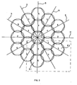
- Another advantageous embodiment of the invention provides five different frequency groups for the network cell, which, as shown in FIG. 2, are distributed over the individual small cells.
- a frequency group 1 is assigned to the middle small cell, the six small cells directly surrounding it are assigned three further frequency groups 2, 3, 4 symmetrically to the cell center Z.
- a fifth frequency group 5 is assigned to the small cells at the corner points, while the three frequency groups 2, 3 and 4, which are already assigned to the small cells surrounding the central small cell, are also assigned to the small cells between the corners.
- the frequency groups 2, 3 and 4 used twice are distributed symmetrically to the center Z of the central small cell so that the centers of small cells of the same frequency groups lie on diagonals H and bisectors S of the central small cell, which enclose a right angle.
- FIG. 3 shows the section indicated in FIG. 2 with two adjacent corner cells E1 and E2 of the same frequency group 5.
- the greatest possible co-channel interference occurs in two adjacent corner cells, since the main beam directions of their antennas are lower include angle as it uenzrios q in all other adjacent small cells of the same Fri is the case.
- the small cells shown in the corner are approximately lines of the same field strength, because the transmit and receive antennas of the fixed radio stations have a cos 2- shaped radiation pattern with the exception of those of the central small cell.
- a mobile radio station that e.g. on the circumference of the corner cell E2, a line of approximately the same field strength, the associated fixed radio station is received with the same field strength everywhere on the circle. Likewise, the mobile radio station is received from all points in the vicinity by the fixed radio station with almost the same field strength.
- the greatest co-channel interference is now always to be expected on the periphery, the edge of a small cell, where the greatest field strength of the neighboring small cell of the same frequency group is measured. It is the point P at which the periphery of the small cell E2 and another circle B touch, which passes through the antenna location of the small cell E1 and whose center M lies on the main beam of the antenna from small cell E1. For reasons of symmetry, it is sufficient to determine the field strength ratio for this one point P, because it is the most unfavorable one that can occur at all.
- a mobile radio station at point P is received by the corresponding fixed radio station in the small cell E2 with the smallest possible field strength, but is disturbed by the fixed radio station in the small cell E1 with the greatest possible field strength. In the opposite direction of transmission, this mobile radio station in the small cell E1 interferes with the reception of another mobile radio station, which moves most strongly on the edge, the periphery, of the small cell E1.
- the field strength ratio can be easily calculated because of the inverse proportionality to the second power of the distances: At point P the field strength from the small cell E2 is inversely proportional to the second power of the double cell radius 2R, the field strength from small cell E1 is inversely proportional to the second power of the double radius 2D of the touching circle B.
- the Feldchverh ä l t n i s then D 2 / R 2 and easy to calculate by means of the illustrated auxiliary lines when observed additionally the honeycomb structure of the network cell.
- Frequency groups necessary.
- the invention manages with only five frequency groups.
- each frequency group consists of ten different frequencies, 750 frequencies are required according to the state of the art, which, however, must be distributed to only five groups in the invention, so that one frequency group in the invention is 15 times more, namely 150 frequencies, having.
- Another advantageous embodiment of the invention which is specified in claim 4, consists in distributing seven frequency groups in a manner known per se over the nineteen small cells.
- a network cell is suitable for areas in which the subscriber density decreases from a center to the outside, as is the case e.g. is often the case in large cities. Many frequencies are required in the city center, but only a few in the peripheral areas. For this reason, the same frequency groups can be assigned to larger areas at the edge of the city area, i.e. at the edge of a network cell, than would be possible in the center. In the invention, this is achieved in that at least two adjacent small cells are assigned the same frequency groups in one or more outer rings.
- One of many such possible exemplary embodiments provides that, in the case of at least two outer rings, at least two corresponding small cells, that is the small cells at and between the corners, have the same frequency groups.
- the central small cell is surrounded by an inner and two outer rings made of small cells, for which a total of five different frequency groups are provided. As shown in Fig.5, corresponding small cells of the two outer rings are assigned the same frequency groups.
- devices can be provided for adjacent small cells of the same frequency group, which have the effect that the same frequency is only ever used in one of these small cells.
- Other devices ensure that the radio traffic of a mobile radio station always takes place with the fixed radio station in whose small cell the mobile radio station is actually located.
- a radio network which is composed of honeycomb cells from network cells according to claim 3, is conceivable, in which the five frequency groups 1, 2, 3, 4 and 5 assigned to the small cells of a network cell are interchanged from network cell to network cell in such a way that only small cells of different frequency groups at the network cell boundaries bump into each other.
- the small cells do not need to have a strictly geometrical hexagonal shape. Some small cells can also be simply omitted. However, this will hardly be the case in areas with a high number of subscribers, for which the radio network according to the invention is particularly suitable.
- a particularly advantageous embodiment of a radio network in which co-channel interference is sufficiently small regardless of the formation of the terrain is specified in claim 8.
- the radio network is composed of network cells according to claim 3 or 4 honeycomb.
- the five or seven frequency groups of a network cell form an upper frequency group, of which four different I, II, III and IV are provided for the entire system.
- the four upper frequency groups I, II, III, IV, each with five different frequency groups, are distributed over the entire radio network in such a way that network cells of the same upper frequency group do not adjoin one another.
- the upper frequency groups I, II, III and IV are evenly distributed over the entire radio network symmetrically to the centers of the network cells.
- co-channel interference can be reduced in that, by exchanging the frequency groups, the outer small cells, which are located on the side of network cells of the same upper frequency group, have no frequency group in common.
- the corresponding distribution of the frequency groups for two network cells III is shown in FIG. In the other network cells I, II and IV, the frequency groups are distributed accordingly to the small cells.
- seven frequency upper groups I, II, III, IV, V, VI and VII are provided for the network cells, according to claim 3 or 4 with five or seven frequency groups, which in a manner known per se, as in Fig.9 shown, are distributed over the network cells.
Landscapes
- Engineering & Computer Science (AREA)
- Computer Networks & Wireless Communication (AREA)
- Signal Processing (AREA)
- Mobile Radio Communication Systems (AREA)
- Radio Relay Systems (AREA)
- Variable-Direction Aerials And Aerial Arrays (AREA)
Priority Applications (1)
| Application Number | Priority Date | Filing Date | Title |
|---|---|---|---|
| AT80102925T ATE1795T1 (de) | 1979-06-07 | 1980-05-24 | Funknetz mit zellenstruktur. |
Applications Claiming Priority (2)
| Application Number | Priority Date | Filing Date | Title |
|---|---|---|---|
| DE2923088 | 1979-06-07 | ||
| DE19792923088 DE2923088A1 (de) | 1979-06-07 | 1979-06-07 | Funknetz mit zellenstruktur |
Publications (2)
| Publication Number | Publication Date |
|---|---|
| EP0021068A1 true EP0021068A1 (de) | 1981-01-07 |
| EP0021068B1 EP0021068B1 (de) | 1982-11-10 |
Family
ID=6072688
Family Applications (1)
| Application Number | Title | Priority Date | Filing Date |
|---|---|---|---|
| EP80102925A Expired EP0021068B1 (de) | 1979-06-07 | 1980-05-24 | Funknetz mit Zellenstruktur |
Country Status (5)
| Country | Link |
|---|---|
| US (1) | US4352110A (es) |
| EP (1) | EP0021068B1 (es) |
| JP (1) | JPS5628537A (es) |
| AT (1) | ATE1795T1 (es) |
| DE (2) | DE2923088A1 (es) |
Cited By (1)
| Publication number | Priority date | Publication date | Assignee | Title |
|---|---|---|---|---|
| DE3130153A1 (de) * | 1981-07-30 | 1983-02-17 | Siemens AG, 1000 Berlin und 8000 München | System zur reduzierung von gleichkanalstoerungen in zellularen mobilfunknetzen mit extrem unterschiedlich grossen nachbar-funkbereichen |
Families Citing this family (8)
| Publication number | Priority date | Publication date | Assignee | Title |
|---|---|---|---|---|
| DE3049011A1 (de) * | 1980-12-24 | 1982-07-08 | TE KA DE Felten & Guilleaume Fernmeldeanlagen GmbH, 8500 Nürnberg | Funknetz mit zellenstruktur |
| US4617573A (en) * | 1984-12-19 | 1986-10-14 | Motorola, Inc. | Method for obtaining a linear cellular array employing cosine-squared antenna patterns |
| US4797682A (en) * | 1987-06-08 | 1989-01-10 | Hughes Aircraft Company | Deterministic thinned aperture phased antenna array |
| GB2292865B (en) * | 1994-08-04 | 1998-05-27 | Northern Telecom Ltd | Cellular communications system |
| JP4808013B2 (ja) * | 2005-12-15 | 2011-11-02 | 富士通株式会社 | 動的セル再構成方法及び,これを適用するセルラーネットワークシステム |
| US7710346B2 (en) * | 2007-06-26 | 2010-05-04 | The Aerospace Corporation | Heptagonal antenna array system |
| US11437731B2 (en) * | 2017-09-13 | 2022-09-06 | Metawave Corporation | Method and apparatus for a passive radiating and feed structure |
| DE102020102033A1 (de) * | 2020-01-28 | 2021-07-29 | Krohne Messtechnik Gmbh | Radar-Antennenanordnung |
Citations (3)
| Publication number | Priority date | Publication date | Assignee | Title |
|---|---|---|---|---|
| DE2365043A1 (de) * | 1973-10-17 | 1975-04-30 | Motorola Inc | Funk-telefonsystem mit tragbaren bzw. mobilen einheiten |
| DE2423603B2 (de) * | 1973-05-15 | 1978-02-23 | Ausscheidung in: 24 62 438 Martin Marietta Corp, Washington, D.C | Verfahren zum zuteilen von frequenzkanaelen in einem funk-telefonie-system |
| DE2806178A1 (de) * | 1977-02-14 | 1978-08-17 | Motorola Inc | Zellenfoermig aufgebautes hf-nachrichtensystem mit einer mehrzahl von antennen |
-
1979
- 1979-06-07 DE DE19792923088 patent/DE2923088A1/de not_active Withdrawn
-
1980
- 1980-05-24 DE DE8080102925T patent/DE3061062D1/de not_active Expired
- 1980-05-24 EP EP80102925A patent/EP0021068B1/de not_active Expired
- 1980-05-24 AT AT80102925T patent/ATE1795T1/de not_active IP Right Cessation
- 1980-06-02 US US06/155,483 patent/US4352110A/en not_active Expired - Lifetime
- 1980-06-04 JP JP7443680A patent/JPS5628537A/ja active Granted
Patent Citations (3)
| Publication number | Priority date | Publication date | Assignee | Title |
|---|---|---|---|---|
| DE2423603B2 (de) * | 1973-05-15 | 1978-02-23 | Ausscheidung in: 24 62 438 Martin Marietta Corp, Washington, D.C | Verfahren zum zuteilen von frequenzkanaelen in einem funk-telefonie-system |
| DE2365043A1 (de) * | 1973-10-17 | 1975-04-30 | Motorola Inc | Funk-telefonsystem mit tragbaren bzw. mobilen einheiten |
| DE2806178A1 (de) * | 1977-02-14 | 1978-08-17 | Motorola Inc | Zellenfoermig aufgebautes hf-nachrichtensystem mit einer mehrzahl von antennen |
Cited By (1)
| Publication number | Priority date | Publication date | Assignee | Title |
|---|---|---|---|---|
| DE3130153A1 (de) * | 1981-07-30 | 1983-02-17 | Siemens AG, 1000 Berlin und 8000 München | System zur reduzierung von gleichkanalstoerungen in zellularen mobilfunknetzen mit extrem unterschiedlich grossen nachbar-funkbereichen |
Also Published As
| Publication number | Publication date |
|---|---|
| DE2923088A1 (de) | 1980-12-18 |
| EP0021068B1 (de) | 1982-11-10 |
| DE3061062D1 (en) | 1982-12-16 |
| JPS6333743B2 (es) | 1988-07-06 |
| ATE1795T1 (de) | 1982-11-15 |
| JPS5628537A (en) | 1981-03-20 |
| US4352110A (en) | 1982-09-28 |
Similar Documents
| Publication | Publication Date | Title |
|---|---|---|
| DE2806178C3 (de) | Zellenförmig aufgebautes HF-Nachrichtensystem mit einer Mehrzahl von Antennen | |
| DE69433396T2 (de) | Verfahren zur Funkkanalzuteilung für Mobilkommunikationssystem | |
| DE4319521C2 (de) | Verfahren zur Verkleinerung und Vergrößerung von randausgeleuchteten Funkzellen in Mobilfunknetzen mit Mehrfachversorgung | |
| EP3025395B1 (de) | Breitband-antennenarray | |
| DE4026432A1 (de) | Planarantenne | |
| EP3220480A1 (de) | Dipolförmige strahleranordnung | |
| EP0852076A1 (de) | Antenne einer zentralstation eines punkt-zu-mehrpunkt-richtfunksystems | |
| EP0657074A1 (de) | Mobiles funknetz | |
| EP0021068B1 (de) | Funknetz mit Zellenstruktur | |
| EP0212113B1 (de) | Funktelefonnetz für ein in Funkzellen aufgeteiltes Funkgebiet | |
| DE2659638B1 (de) | Funksystem zum Anschluss ortsfester Teilnehmerstationen an ein Nachrichtennetz | |
| DE1042674B (de) | Drehfunkfeuerantenne mit verbesserter Vertikalstrahlung | |
| DE2659570C2 (de) | Fernsprech- und Datennetz für ortsfeste und mobile Teilnehmerstationen | |
| EP0654201B1 (de) | Verfahren und vorrichtung für ein mikrozellulares gleichkanalfunksystem | |
| DE3049011C2 (es) | ||
| EP0640260B1 (de) | Mobiles funknetz mit zentraler ausleuchtung der zellen | |
| DE4318495C2 (de) | Verfahren zur verbesserten Frequenzzuweisung bei einem zellularen Mobilfunksystem mit Mehrfachversorgung | |
| EP0041179B1 (de) | Mobilfunksystem mit Hauptkanälen für die drahtlose Kommunikation zwischen und mit Mobilteilnehmergeräten und mit Subkanälen für drahtlose Nahverbindungen zwischen Mobilteilnehmergeräten und diesen zugeordneten tragbaren Kommunikationsgeräten | |
| DE2150434C2 (de) | Peilantennensystem zur Peilung bei Mehrwelleneinfall mit Hilfe eines Rechners | |
| DE957857C (de) | Schlitzantenne | |
| EP0573970A1 (de) | Rundstrahlantenne | |
| EP2018779B1 (de) | Zuordnung von frequenzbereichen für uplink- und downlink-übertragungen | |
| DE2936983A1 (de) | Funknetz mit netzzellenstruktur | |
| EP1202387A2 (de) | Planarantenne mit verbesserter Richtcharakteristik | |
| DE3130153A1 (de) | System zur reduzierung von gleichkanalstoerungen in zellularen mobilfunknetzen mit extrem unterschiedlich grossen nachbar-funkbereichen |
Legal Events
| Date | Code | Title | Description |
|---|---|---|---|
| PUAI | Public reference made under article 153(3) epc to a published international application that has entered the european phase |
Free format text: ORIGINAL CODE: 0009012 |
|
| AK | Designated contracting states |
Designated state(s): AT CH DE FR GB NL SE |
|
| 17P | Request for examination filed |
Effective date: 19810331 |
|
| GRAA | (expected) grant |
Free format text: ORIGINAL CODE: 0009210 |
|
| AK | Designated contracting states |
Designated state(s): AT CH DE FR GB LI NL SE |
|
| REF | Corresponds to: |
Ref document number: 1795 Country of ref document: AT Date of ref document: 19821115 Kind code of ref document: T |
|
| REF | Corresponds to: |
Ref document number: 3061062 Country of ref document: DE Date of ref document: 19821216 |
|
| ET | Fr: translation filed | ||
| RAP2 | Party data changed (patent owner data changed or rights of a patent transferred) |
Owner name: FELTEN & GUILLEAUME FERNMELDEANLAGEN GMBH |
|
| PGFP | Annual fee paid to national office [announced via postgrant information from national office to epo] |
Ref country code: NL Payment date: 19850531 Year of fee payment: 6 |
|
| PG25 | Lapsed in a contracting state [announced via postgrant information from national office to epo] |
Ref country code: NL Effective date: 19861201 |
|
| NLV4 | Nl: lapsed or anulled due to non-payment of the annual fee | ||
| PGFP | Annual fee paid to national office [announced via postgrant information from national office to epo] |
Ref country code: DE Payment date: 19900725 Year of fee payment: 11 |
|
| PGFP | Annual fee paid to national office [announced via postgrant information from national office to epo] |
Ref country code: CH Payment date: 19900824 Year of fee payment: 11 |
|
| PGFP | Annual fee paid to national office [announced via postgrant information from national office to epo] |
Ref country code: GB Payment date: 19910501 Year of fee payment: 12 |
|
| PGFP | Annual fee paid to national office [announced via postgrant information from national office to epo] |
Ref country code: FR Payment date: 19910522 Year of fee payment: 12 |
|
| PGFP | Annual fee paid to national office [announced via postgrant information from national office to epo] |
Ref country code: AT Payment date: 19910523 Year of fee payment: 12 |
|
| PGFP | Annual fee paid to national office [announced via postgrant information from national office to epo] |
Ref country code: SE Payment date: 19910524 Year of fee payment: 12 |
|
| PG25 | Lapsed in a contracting state [announced via postgrant information from national office to epo] |
Ref country code: LI Effective date: 19910531 Ref country code: CH Effective date: 19910531 |
|
| REG | Reference to a national code |
Ref country code: CH Ref legal event code: PL |
|
| PG25 | Lapsed in a contracting state [announced via postgrant information from national office to epo] |
Ref country code: DE Effective date: 19920303 |
|
| PG25 | Lapsed in a contracting state [announced via postgrant information from national office to epo] |
Ref country code: GB Effective date: 19920524 Ref country code: AT Effective date: 19920524 |
|
| PG25 | Lapsed in a contracting state [announced via postgrant information from national office to epo] |
Ref country code: SE Effective date: 19920525 |
|
| GBPC | Gb: european patent ceased through non-payment of renewal fee |
Effective date: 19920524 |
|
| PG25 | Lapsed in a contracting state [announced via postgrant information from national office to epo] |
Ref country code: FR Effective date: 19930129 |
|
| REG | Reference to a national code |
Ref country code: FR Ref legal event code: ST |
|
| EUG | Se: european patent has lapsed |
Ref document number: 80102925.7 Effective date: 19921204 |
|
| PLBE | No opposition filed within time limit |
Free format text: ORIGINAL CODE: 0009261 |
|
| STAA | Information on the status of an ep patent application or granted ep patent |
Free format text: STATUS: NO OPPOSITION FILED WITHIN TIME LIMIT |