EP0022645A2 - Integrated heat exchange and heat storage system using low-temperature thermochemical reactions - Google Patents
Integrated heat exchange and heat storage system using low-temperature thermochemical reactions Download PDFInfo
- Publication number
- EP0022645A2 EP0022645A2 EP80302287A EP80302287A EP0022645A2 EP 0022645 A2 EP0022645 A2 EP 0022645A2 EP 80302287 A EP80302287 A EP 80302287A EP 80302287 A EP80302287 A EP 80302287A EP 0022645 A2 EP0022645 A2 EP 0022645A2
- Authority
- EP
- European Patent Office
- Prior art keywords
- heat
- tubes
- substance
- fluid
- yielding
- Prior art date
- Legal status (The legal status is an assumption and is not a legal conclusion. Google has not performed a legal analysis and makes no representation as to the accuracy of the status listed.)
- Withdrawn
Links
Images

Classifications
-
- F—MECHANICAL ENGINEERING; LIGHTING; HEATING; WEAPONS; BLASTING
- F28—HEAT EXCHANGE IN GENERAL
- F28D—HEAT-EXCHANGE APPARATUS, NOT PROVIDED FOR IN ANOTHER SUBCLASS, IN WHICH THE HEAT-EXCHANGE MEDIA DO NOT COME INTO DIRECT CONTACT
- F28D20/00—Heat storage plants or apparatus in general; Regenerative heat-exchange apparatus not covered by groups F28D17/00 or F28D19/00
- F28D20/003—Heat storage plants or apparatus in general; Regenerative heat-exchange apparatus not covered by groups F28D17/00 or F28D19/00 using thermochemical reactions
-
- Y—GENERAL TAGGING OF NEW TECHNOLOGICAL DEVELOPMENTS; GENERAL TAGGING OF CROSS-SECTIONAL TECHNOLOGIES SPANNING OVER SEVERAL SECTIONS OF THE IPC; TECHNICAL SUBJECTS COVERED BY FORMER USPC CROSS-REFERENCE ART COLLECTIONS [XRACs] AND DIGESTS
- Y02—TECHNOLOGIES OR APPLICATIONS FOR MITIGATION OR ADAPTATION AGAINST CLIMATE CHANGE
- Y02E—REDUCTION OF GREENHOUSE GAS [GHG] EMISSIONS, RELATED TO ENERGY GENERATION, TRANSMISSION OR DISTRIBUTION
- Y02E60/00—Enabling technologies; Technologies with a potential or indirect contribution to GHG emissions mitigation
- Y02E60/14—Thermal energy storage
-
- Y—GENERAL TAGGING OF NEW TECHNOLOGICAL DEVELOPMENTS; GENERAL TAGGING OF CROSS-SECTIONAL TECHNOLOGIES SPANNING OVER SEVERAL SECTIONS OF THE IPC; TECHNICAL SUBJECTS COVERED BY FORMER USPC CROSS-REFERENCE ART COLLECTIONS [XRACs] AND DIGESTS
- Y02—TECHNOLOGIES OR APPLICATIONS FOR MITIGATION OR ADAPTATION AGAINST CLIMATE CHANGE
- Y02E—REDUCTION OF GREENHOUSE GAS [GHG] EMISSIONS, RELATED TO ENERGY GENERATION, TRANSMISSION OR DISTRIBUTION
- Y02E70/00—Other energy conversion or management systems reducing GHG emissions
- Y02E70/30—Systems combining energy storage with energy generation of non-fossil origin
-
- Y—GENERAL TAGGING OF NEW TECHNOLOGICAL DEVELOPMENTS; GENERAL TAGGING OF CROSS-SECTIONAL TECHNOLOGIES SPANNING OVER SEVERAL SECTIONS OF THE IPC; TECHNICAL SUBJECTS COVERED BY FORMER USPC CROSS-REFERENCE ART COLLECTIONS [XRACs] AND DIGESTS
- Y10—TECHNICAL SUBJECTS COVERED BY FORMER USPC
- Y10S—TECHNICAL SUBJECTS COVERED BY FORMER USPC CROSS-REFERENCE ART COLLECTIONS [XRACs] AND DIGESTS
- Y10S165/00—Heat exchange
- Y10S165/539—Heat exchange having a heat storage mass
Definitions
- This invention relates to an integrated system adapted to use and exploit substances in solid and paste form which are capable of thermochemical, e.g. exo-endothermic, reactions at temperatures generally below 100°C, and more particularly in the range between 20 and 60°C, as a means for term storage of thermal energy.
- thermochemical reaction with change of phase forming the subject matter of European Patent Application No. 79300430.0. entitled "Storage of Thermal Energy”.
- the first reaction occurs to the right at a temperature above approximately 22°C with a storage capacity of approximately 80 kcal/litre.
- the heat absorbed is yielded in the subsequent dissociation down to temperatures below 22°C.
- the heat-storing and -yielding substance is in the form of a partially crystallized pasty material with a slight excess of water, when the reaction is shifted to the left after yielding the absorbed energy, and a very fine suspension in an aqueous solution when the reaction is shifted to the right after absorbing heat.
- the average density of the substance is 1.6 grams/ml.
- Another substance suitable for use in this invention comprises reciprocal salt pairs such as: whose transformation temperature is 64°C - i.e., the substance can store heat above 64°C and yield it below 64°C.
- the integrated heat exchange and heat storage system utilizing thermochemical reactions comprises: a bunch of parallel adjacent tubes containing a substance for storing and yielding heat, and a group of tubes parallel to the first-mentioned tubes and interposed therebetween and containing a fluid, heat-carrying vehicle; this system of tubes being disposed in a receptacle whose major axis extends parallel to the axis extends parallel to the axis of the tubes, wherein the voids between the tubes are filled with a stagnant liquid serving to facilitate heat exchange between the fluid, heat-carrying vehicle and the substance for storing and yielding heat.
- the heat-storing and -yielding substance is an exo-endothermic mixture.
- the fluid, heat-carrying vehicle is water.
- thermochemical reactions used and the chemicals mentioned are exploited in the solid or pasty state; the viscosity depending on how much liquid, usually water, is in excess and therefore upon the temperature for filling the e.g. cylindrical and preferably plastic, e.g. polypropylene, tubes. Volume variations are absorbed by slight deformations of the plastics tubes which are closed at their ends and which have a diameter or approximately from 10 to 20 mm. A tube bunch forming 'a storage volume or mass is produced by combining a number of such tubes with their axes parallel to one another.
- a receptacle 1 for a bunch of tubes 2 which are made of a plastics material, such as polypropylene or polyethylene; the walls of the receptacle 1 being 2 mm thick.
- the bunch consists of 25 tubes made of the same material as the receptacle 1.
- Each tube 2 has an outside diameter of 19 mm, is 1.6 mm thick and contains a fluid or pasty heat-storing and -yielding substance 10.
- tubes 3 Disposed in the gaps between the tubes 2 coaxially thereof are tubes 3 which are also made of a plastics material, have an outside diameter of 8 mm, are 1 mm thick and carry a flow of a fluid, heat-carrying vehicle, usually water 11.
- the same serves to supply heat during the supply phase and to recover the stored heat during the recovery phase.
- Heat exchange between the fluid flowing through the tubes 3 and the storage substance in the tubes 2 is by conduction through the plastics material walls of the tubes and through the solid or pasty substance which is disposed in the tubes and in which the thermochemical transformation of storage and yielding of heat occurs gradually in one direction or the other.
- Stagnant water is provided in gaps 12 between the tubes 2 and 3 to facilitate heat exchange between the two kinds of tube.
- the water piping 3 can be connected in parallel between the two ends of the receptacle 1 or can be subdivided into two halves connected in series and each consisting of parallel-connected tubes. Consequently, and as shown in Figure 2, the heat-carrying vehicle can flow through the receptacle 1 in both directions, and so the input tube 4 and discharge tube 5 would be arranged at the same ends of the system.
- the element shown by way of example in Figures 1 and 2 measure 10 x 10 cm, is 2 m long, and has a capacity of 20 litres of which 11.5 litres consist of the actual volume available for the storage substance 3.5 litres are stagnant water and 1.25 litre are circulating water.
- a heat storage and exchange volume of a total of some 2 m 3 is provided containing 1.15 m 3 of a mixture of salts suitable for providing heat storage by means of a thermochemical reaction.
- the volume obtained by combining individual units or modules can readily be thermally insulated by placing a layer or wrapping of heat insulant 13, such as glass wool or expanded polystyrene, around.the outside.
- heat insulant 13 such as glass wool or expanded polystyrene
- the fluid supplying the heat energy such as hot water from solar collectors (operating in the daytime or summer) or the fluid for recovering the stored heat, such as water for heating system of a house (during the night or in the winter) can flow in various ways in series or parallel between the various modules in . dependence upon the form of connection used between the supply and discharge tubes and the end plates.
- the invention described is not limited to the embodiment disclosed and the proposed system is suitable for various geometric layouts different from those described and for the use of constructional materials and heat storage substances of various kinds, including solid substances and without change of phase.
Abstract
Description
- This invention relates to an integrated system adapted to use and exploit substances in solid and paste form which are capable of thermochemical, e.g. exo-endothermic, reactions at temperatures generally below 100°C, and more particularly in the range between 20 and 60°C, as a means for term storage of thermal energy.
- By way, of example, reference will be made to the thermochemical reaction with change of phase forming the subject matter of European Patent Application No. 79300430.0. entitled "Storage of Thermal Energy".
- That patent application is based on the use of the following reactions in a slight excess of water:


- The first reaction occurs to the right at a temperature above approximately 22°C with a storage capacity of approximately 80 kcal/litre. The heat absorbed is yielded in the subsequent dissociation down to temperatures below 22°C. The heat-storing and -yielding substance is in the form of a partially crystallized pasty material with a slight excess of water, when the reaction is shifted to the left after yielding the absorbed energy, and a very fine suspension in an aqueous solution when the reaction is shifted to the right after absorbing heat. The average density of the substance is 1.6 grams/ml.
- Another substance suitable for use in this invention comprises reciprocal salt pairs such as:

- According to the main feature of the present invention, the integrated heat exchange and heat storage system utilizing thermochemical reactions comprises: a bunch of parallel adjacent tubes containing a substance for storing and yielding heat, and a group of tubes parallel to the first-mentioned tubes and interposed therebetween and containing a fluid, heat-carrying vehicle; this system of tubes being disposed in a receptacle whose major axis extends parallel to the axis extends parallel to the axis of the tubes, wherein the voids between the tubes are filled with a stagnant liquid serving to facilitate heat exchange between the fluid, heat-carrying vehicle and the substance for storing and yielding heat.
- According to another feature of the invention, the heat-storing and -yielding substance is an exo-endothermic mixture.
- According to another feature of the invention, the fluid, heat-carrying vehicle is water.
- The thermochemical reactions used and the chemicals mentioned are exploited in the solid or pasty state; the viscosity depending on how much liquid, usually water, is in excess and therefore upon the temperature for filling the e.g. cylindrical and preferably plastic, e.g. polypropylene, tubes. Volume variations are absorbed by slight deformations of the plastics tubes which are closed at their ends and which have a diameter or approximately from 10 to 20 mm. A tube bunch forming 'a storage volume or mass is produced by combining a number of such tubes with their axes parallel to one another.
- Two embodiments of the integrated system in accordance with this invention are shown in the accompanying drawings, wherein:
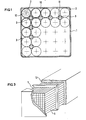
- Figure 1 is a view in cross-section of a storage unit or module consisting of a bunch of tubes in a square box;
- Figure 2 is a view in longitudinal section of the ends of the tube bunch and associated box, and
- Figure 3 is a perspective view of how various storage modules or units can be combined one beside another and thermally insulated all the way round to provide considerable thermal storage in a small volume.
- Referring to Figure 1, there can be seen a receptacle 1 for a bunch of
tubes 2 which are made of a plastics material, such as polypropylene or polyethylene; the walls of the receptacle 1 being 2 mm thick. The bunch consists of 25 tubes made of the same material as the receptacle 1. Eachtube 2 has an outside diameter of 19 mm, is 1.6 mm thick and contains a fluid or pasty heat-storing and -yieldingsubstance 10. Disposed in the gaps between thetubes 2 coaxially thereof aretubes 3 which are also made of a plastics material, have an outside diameter of 8 mm, are 1 mm thick and carry a flow of a fluid, heat-carrying vehicle, usuallywater 11. The same serves to supply heat during the supply phase and to recover the stored heat during the recovery phase. Heat exchange between the fluid flowing through thetubes 3 and the storage substance in thetubes 2 is by conduction through the plastics material walls of the tubes and through the solid or pasty substance which is disposed in the tubes and in which the thermochemical transformation of storage and yielding of heat occurs gradually in one direction or the other. Stagnant water is provided ingaps 12 between thetubes - The
water piping 3 can be connected in parallel between the two ends of the receptacle 1 or can be subdivided into two halves connected in series and each consisting of parallel-connected tubes. Consequently, and as shown in Figure 2, the heat-carrying vehicle can flow through the receptacle 1 in both directions, and so the input tube 4 and discharge tube 5 would be arranged at the same ends of the system. - The element shown by way of example in Figures 1 and 2 measure 10 x 10 cm, is 2 m long, and has a capacity of 20 litres of which 11.5 litres consist of the actual volume available for the storage substance 3.5 litres are stagnant water and 1.25 litre are circulating water.
- As shown in Figure 2, all the
tubes 2 are closed at both ends 6,7 which are secured in the receptacle 1 by means.of two end plates 8,9. - If 100 elements are combined as shown in Figure 3, a heat storage and exchange volume of a total of some 2
m 3 is provided containing 1.15 m3 of a mixture of salts suitable for providing heat storage by means of a thermochemical reaction. - The volume obtained by combining individual units or modules can readily be thermally insulated by placing a layer or wrapping of
heat insulant 13, such as glass wool or expanded polystyrene, around.the outside. - The fluid supplying the heat energy, such as hot water from solar collectors (operating in the daytime or summer) or the fluid for recovering the stored heat, such as water for heating system of a house (during the night or in the winter) can flow in various ways in series or parallel between the various modules in . dependence upon the form of connection used between the supply and discharge tubes and the end plates.
- The invention described is not limited to the embodiment disclosed and the proposed system is suitable for various geometric layouts different from those described and for the use of constructional materials and heat storage substances of various kinds, including solid substances and without change of phase.
Claims (5)
Applications Claiming Priority (2)
| Application Number | Priority Date | Filing Date | Title |
|---|---|---|---|
| IT4973679 | 1979-07-12 | ||
| IT49736/79A IT1162348B (en) | 1979-07-12 | 1979-07-12 | INTEGRATED SYSTEM FOR HEAT EXCHANGE AND STORAGE OF THERMAL ENERGY THROUGH LOW TEMPERATURE THERMOCHEMICAL REACTIONS |
Publications (2)
| Publication Number | Publication Date |
|---|---|
| EP0022645A2 true EP0022645A2 (en) | 1981-01-21 |
| EP0022645A3 EP0022645A3 (en) | 1981-03-25 |
Family
ID=11271454
Family Applications (1)
| Application Number | Title | Priority Date | Filing Date |
|---|---|---|---|
| EP80302287A Withdrawn EP0022645A3 (en) | 1979-07-12 | 1980-07-04 | Integrated heat exchange and heat storage system using low-temperature thermochemical reactions |
Country Status (4)
| Country | Link |
|---|---|
| US (1) | US4362207A (en) |
| EP (1) | EP0022645A3 (en) |
| CA (1) | CA1121800A (en) |
| IT (1) | IT1162348B (en) |
Cited By (2)
| Publication number | Priority date | Publication date | Assignee | Title |
|---|---|---|---|---|
| FR2544204A1 (en) * | 1983-04-12 | 1984-10-19 | Air Liquide | CHEMICAL OXYGEN BREATHING APPARATUS |
| DE102015002663B4 (en) | 2015-03-02 | 2020-06-10 | Grenzebach Maschinenbau Gmbh | Method and device for inexpensive cutting of profiles in vehicle tires |
Families Citing this family (14)
| Publication number | Priority date | Publication date | Assignee | Title |
|---|---|---|---|---|
| US4624242A (en) * | 1985-08-13 | 1986-11-25 | Examplar | Solar heat transfer and storage system |
| US4807696A (en) * | 1987-12-10 | 1989-02-28 | Triangle Research And Development Corp. | Thermal energy storage apparatus using encapsulated phase change material |
| US4976308A (en) * | 1990-02-21 | 1990-12-11 | Wright State University | Thermal energy storage heat exchanger |
| US5000252A (en) * | 1990-02-22 | 1991-03-19 | Wright State University | Thermal energy storage system |
| US5553662A (en) * | 1993-12-10 | 1996-09-10 | Store Heat & Producte Energy, Inc. | Plumbed thermal energy storage system |
| US6059016A (en) * | 1994-08-11 | 2000-05-09 | Store Heat And Produce Energy, Inc. | Thermal energy storage and delivery system |
| US6079481A (en) * | 1997-01-23 | 2000-06-27 | Ail Research, Inc | Thermal storage system |
| US6047106A (en) * | 1997-01-30 | 2000-04-04 | Salyer; Ival O. | Water heating unit with integral thermal energy storage |
| US6493507B2 (en) | 1997-01-30 | 2002-12-10 | Ival O. Salyer | Water heating unit with integral thermal energy storage |
| JP4574783B2 (en) * | 2000-03-07 | 2010-11-04 | 株式会社豊田自動織機 | Hydrogen storage alloy tank |
| US6889751B1 (en) * | 2000-10-04 | 2005-05-10 | Modine Manufacturing Company | Latent heat storage device |
| US7980293B2 (en) * | 2008-03-21 | 2011-07-19 | Honeywell International Inc. | Two fluid thermal storage device to allow for independent heating and cooling |
| US20150211805A1 (en) * | 2014-01-29 | 2015-07-30 | Kunshan Jue-Chung Electronics Co., Ltd. | Thermostat module |
| US11747094B2 (en) * | 2017-05-12 | 2023-09-05 | The Boeing Company | Hollow lattice thermal energy storage heat exchanger |
Citations (4)
| Publication number | Priority date | Publication date | Assignee | Title |
|---|---|---|---|---|
| GB847984A (en) * | 1957-10-17 | 1960-09-14 | Babcock & Wilcox France | Improvements in and relating to heat exchangers |
| DE2552698A1 (en) * | 1975-11-25 | 1977-06-02 | Erno Raumfahrttechnik Gmbh | Large capacity heat storage device - has filled hollow elastic balls for infill in side insulating container |
| FR2365093A1 (en) * | 1976-09-21 | 1978-04-14 | Bergeon Et Cie | Heat exchanger and accumulator using hydrated salt - has water flow path made from two parallel zigzag sheets in housing |
| DE2741829A1 (en) * | 1977-09-16 | 1979-03-22 | Dornier System Gmbh | Latent heat storage material of encapsulated wax in liquid medium - allowing heat transfer by convection |
Family Cites Families (5)
| Publication number | Priority date | Publication date | Assignee | Title |
|---|---|---|---|---|
| US4166449A (en) * | 1975-04-28 | 1979-09-04 | Depew Walter L | Heat storage vault |
| DE2602530B1 (en) * | 1976-01-23 | 1977-05-18 | Inst Fuer Kerntechnik & Energ | LATENTHEAT STORAGE |
| CH609140A5 (en) * | 1976-05-18 | 1979-02-15 | Sulzer Ag | |
| US4146057A (en) * | 1977-11-07 | 1979-03-27 | Rockwell International Corporation | Thermal buffer system |
| NL168929C (en) * | 1978-03-23 | 1982-05-17 | Stichting Bouwcentrum | SOLAR HEATING DEVICE AND HEAT ACCUMULATORS FOR USE THEREIN. |
-
1979
- 1979-07-12 IT IT49736/79A patent/IT1162348B/en active
-
1980
- 1980-07-04 EP EP80302287A patent/EP0022645A3/en not_active Withdrawn
- 1980-07-10 CA CA000355946A patent/CA1121800A/en not_active Expired
- 1980-07-14 US US06/168,067 patent/US4362207A/en not_active Expired - Lifetime
Patent Citations (4)
| Publication number | Priority date | Publication date | Assignee | Title |
|---|---|---|---|---|
| GB847984A (en) * | 1957-10-17 | 1960-09-14 | Babcock & Wilcox France | Improvements in and relating to heat exchangers |
| DE2552698A1 (en) * | 1975-11-25 | 1977-06-02 | Erno Raumfahrttechnik Gmbh | Large capacity heat storage device - has filled hollow elastic balls for infill in side insulating container |
| FR2365093A1 (en) * | 1976-09-21 | 1978-04-14 | Bergeon Et Cie | Heat exchanger and accumulator using hydrated salt - has water flow path made from two parallel zigzag sheets in housing |
| DE2741829A1 (en) * | 1977-09-16 | 1979-03-22 | Dornier System Gmbh | Latent heat storage material of encapsulated wax in liquid medium - allowing heat transfer by convection |
Cited By (4)
| Publication number | Priority date | Publication date | Assignee | Title |
|---|---|---|---|---|
| FR2544204A1 (en) * | 1983-04-12 | 1984-10-19 | Air Liquide | CHEMICAL OXYGEN BREATHING APPARATUS |
| EP0125157A1 (en) * | 1983-04-12 | 1984-11-14 | L'air Liquide, Societe Anonyme Pour L'etude Et L'exploitation Des Procedes Georges Claude | Chemical oxygen generator for breathing equipment |
| US4717549A (en) * | 1983-04-12 | 1988-01-05 | L'air Liquide, Societe Anonyme Pour L'etude Et L'exploitation Des Procedes Georges Claude | Oxygen chemical generation respiration apparatus |
| DE102015002663B4 (en) | 2015-03-02 | 2020-06-10 | Grenzebach Maschinenbau Gmbh | Method and device for inexpensive cutting of profiles in vehicle tires |
Also Published As
| Publication number | Publication date |
|---|---|
| EP0022645A3 (en) | 1981-03-25 |
| US4362207A (en) | 1982-12-07 |
| CA1121800A (en) | 1982-04-13 |
| IT7949736A0 (en) | 1979-07-12 |
| IT1162348B (en) | 1987-03-25 |
Similar Documents
| Publication | Publication Date | Title |
|---|---|---|
| EP0022645A2 (en) | Integrated heat exchange and heat storage system using low-temperature thermochemical reactions | |
| Sharma et al. | Latent heat storage materials and systems: a review | |
| Kaygusuz | Experimental and theoretical investigation of latent heat storage for water based solar heating systems | |
| US4258696A (en) | Passive thermal energy phase change storage apparatus | |
| Shukla et al. | Solar water heaters with phase change material thermal energy storage medium: A review | |
| Fath | Thermal performance of a simple design solar air heater with built-in thermal energy storage system | |
| US4355627A (en) | Thermal storage system | |
| Bansal et al. | An analytical study of a latent heat storage system in a cylinder | |
| CA1121677A (en) | Heat storage apparatus and heat exchanger element for use therein | |
| CN1229466A (en) | Equipment and process for heat energy storage | |
| CN207570148U (en) | A kind of solar energy heat-collecting heat-storage system | |
| CN106123661A (en) | A kind of micro heat pipe array board phase transformation stores exothermic processes and system | |
| US4176655A (en) | Solar energy collection system and apparatus for same utilizing latent energy storage fluid | |
| US4313424A (en) | Solar heating system | |
| GB2030282A (en) | An integrated system for collecting and storing solar energy | |
| CN203671959U (en) | Three-cavity fluid focused solar energy photo-thermal heating, heat transmission and heat storage system | |
| CN106016786A (en) | Water tank-free type solar phase change heat storage water heater | |
| JPS58133561A (en) | Latent heat accumulating type solar heat collector | |
| SU1620786A1 (en) | Measuring device for meter of group delay time | |
| CN213335017U (en) | Solar heat storage water heater | |
| Al-Mudhafar | Innovative heat transfer enhancements for thermal energy storage systems based on phase change materials | |
| Vaidhyanathan et al. | Theoretical and Experimental Modeling of Phase Change Material-Based Space Heating Using Solar Energy | |
| Gaur | Latent heat utilization approach and the role of phase change materials | |
| JPS60256797A (en) | Heat accumulating and heat exchanging device | |
| Kashyap et al. | Numerical Simulation of Latent Heat Thermal Energy Storage Incorporated Solar Water Heater |
Legal Events
| Date | Code | Title | Description |
|---|---|---|---|
| PUAI | Public reference made under article 153(3) epc to a published international application that has entered the european phase |
Free format text: ORIGINAL CODE: 0009012 |
|
| PUAL | Search report despatched |
Free format text: ORIGINAL CODE: 0009013 |
|
| AK | Designated contracting states |
Designated state(s): BE CH DE FR GB LU NL SE |
|
| AK | Designated contracting states |
Designated state(s): BE CH DE FR GB LU NL SE |
|
| 17P | Request for examination filed |
Effective date: 19810921 |
|
| STAA | Information on the status of an ep patent application or granted ep patent |
Free format text: STATUS: THE APPLICATION IS DEEMED TO BE WITHDRAWN |
|
| 18D | Application deemed to be withdrawn |
Effective date: 19821229 |
|
| RIN1 | Information on inventor provided before grant (corrected) |
Inventor name: FARFALETTI-CASALI, FLAVIANO Inventor name: REITER, FRIEDRICH Inventor name: NOBEL, LEENDERT Inventor name: BUZZI, UMBERTO |