EP0025332A1 - Labelling machine and method, apparatus and method of severing film for use therein and container labelled thereby - Google Patents
Labelling machine and method, apparatus and method of severing film for use therein and container labelled thereby Download PDFInfo
- Publication number
- EP0025332A1 EP0025332A1 EP80303040A EP80303040A EP0025332A1 EP 0025332 A1 EP0025332 A1 EP 0025332A1 EP 80303040 A EP80303040 A EP 80303040A EP 80303040 A EP80303040 A EP 80303040A EP 0025332 A1 EP0025332 A1 EP 0025332A1
- Authority
- EP
- European Patent Office
- Prior art keywords
- label
- cutting
- container
- link
- leading end
- Prior art date
- Legal status (The legal status is an assumption and is not a legal conclusion. Google has not performed a legal analysis and makes no representation as to the accuracy of the status listed.)
- Withdrawn
Links
Images


Classifications
-
- B—PERFORMING OPERATIONS; TRANSPORTING
- B65—CONVEYING; PACKING; STORING; HANDLING THIN OR FILAMENTARY MATERIAL
- B65C—LABELLING OR TAGGING MACHINES, APPARATUS, OR PROCESSES
- B65C9/00—Details of labelling machines or apparatus
- B65C9/08—Label feeding
- B65C9/18—Label feeding from strips, e.g. from rolls
- B65C9/1803—Label feeding from strips, e.g. from rolls the labels being cut from a strip
- B65C9/1815—Label feeding from strips, e.g. from rolls the labels being cut from a strip and transferred by suction means
- B65C9/1819—Label feeding from strips, e.g. from rolls the labels being cut from a strip and transferred by suction means the suction means being a vacuum drum
-
- B—PERFORMING OPERATIONS; TRANSPORTING
- B26—HAND CUTTING TOOLS; CUTTING; SEVERING
- B26F—PERFORATING; PUNCHING; CUTTING-OUT; STAMPING-OUT; SEVERING BY MEANS OTHER THAN CUTTING
- B26F3/00—Severing by means other than cutting; Apparatus therefor
- B26F3/002—Precutting and tensioning or breaking
-
- B—PERFORMING OPERATIONS; TRANSPORTING
- B65—CONVEYING; PACKING; STORING; HANDLING THIN OR FILAMENTARY MATERIAL
- B65C—LABELLING OR TAGGING MACHINES, APPARATUS, OR PROCESSES
- B65C3/00—Labelling other than flat surfaces
- B65C3/06—Affixing labels to short rigid containers
- B65C3/08—Affixing labels to short rigid containers to container bodies
- B65C3/14—Affixing labels to short rigid containers to container bodies the container being positioned for labelling with its centre-line vertical
- B65C3/16—Affixing labels to short rigid containers to container bodies the container being positioned for labelling with its centre-line vertical by rolling the labels onto cylindrical containers, e.g. bottles
-
- B—PERFORMING OPERATIONS; TRANSPORTING
- B65—CONVEYING; PACKING; STORING; HANDLING THIN OR FILAMENTARY MATERIAL
- B65C—LABELLING OR TAGGING MACHINES, APPARATUS, OR PROCESSES
- B65C9/00—Details of labelling machines or apparatus
- B65C9/08—Label feeding
- B65C9/18—Label feeding from strips, e.g. from rolls
- B65C9/1803—Label feeding from strips, e.g. from rolls the labels being cut from a strip
- B65C2009/1834—Details of cutting means
- B65C2009/1857—Details of cutting means two co-acting knifes
- B65C2009/1861—Details of cutting means two co-acting knifes whereby one knife remains stationary
Landscapes
- Life Sciences & Earth Sciences (AREA)
- Forests & Forestry (AREA)
- Engineering & Computer Science (AREA)
- Mechanical Engineering (AREA)
- Labeling Devices (AREA)
Abstract
A labelling machine is arranged to sever labels from continuous label stock (11), to apply each severed label (15) to a rotary vacuum drum (16), apply adhesive to the label by means of a glue wheel (17), apply each label with adhesive on it to a container (19) and to wrap the label (15) around the container (19). The machine is arranged to partially sever each label from continuous label stock by means of moving (44) and stationary cutting blades (42) in a manner such asto leave an easily ruptured link to the following unsevered label, such link being ruptured by tension exerted by the vacuum drum (16). The containers are provided with a plastic label (15). The machine and corresponding method of operation are advantageous as applied to limp, easily deformed label stock, and to avoid the need to preform labels into tubes to be slipped over the container.
Description
- This invention relates to a method of and apparatus for severing a continuous length of film material and to a labelling machine and method. A labelling machine is known in which a roll of label stock is provided; the label stock is pulled from the roll and is cut into individual labels by a cutter; the labels are deposited on a rotating vacuum drum which, after application of glue to the leading edge and the trailing edge (or to the entire exposed surface) of the label, the label is applied to a container, the containers being supplied for such purpose. The feed of label stock may be continuous and operation of the cutter, the vacuum drum and the container feed are continuous. Representative patents of this type of labelling machine are U.S. Patents Nos. 4,108,709; 4,108,710 and 4,108,711.
- The labelling machine of the present invention is preferably a continuously operating machine but it may be applicable to other modes of operation, for example a machine which carries out labelling intermittently but is supplied by a continuous length of label stock from a roll.
- A type of label that is becoming increasingly common, particularly for what are known as PET (polyethylene terephthalate) containers, is a very thin, very pliable and limp material made of polypropylene. Such label material is advantageous because, among other things, it is resistant to moisture. Also, it accommodates itself to deformation of the container during handling. However, unless such label material is laminated to paper it is too limp to be fed continuously and at high speed (e.g., 150 to 200 labels per minute or more) from a cutter to a vacuum label drum. The material bends, folds or is otherwise distorted resulting in inaccurate label application. Further, such plastic material is prone to acquire an electrostatic charge which causes it to adhere to and to follow a cutting blade. Therefore, it has been the practice to laminate such plastic material to a specially treated paper which is available at present from only a single source, and even so it suffers from the problem of electrostatic charge. An alternative expedient is to preform the limp label stock into tubes which are slipped over the containers.
- The expedient of preforming labels into tubes is expensive, the rate of labelling is undesirably slow, and it is not possible to adhere the preformed labels to the containers. Therefore, a label, once having been applied as a preformed tube, will slip on the container and misalignment will occur. Furthermore, if there are irregularities in the surface of the container difficulties arise in applying the preformed tubes to the containers. Also, it is not possible to apply partial labels, i.e., labels which do not wrap entirely around the container, by this method.
- It is an object of the present invention to provide a labelling machine and a labelling method which will effectively and at high speed sever labels from continuous label stock of limp plastic label material and which will accurately and dependably supply the labels to a rotating vacuum drum and thereby to a container.
- According to a first aspect of the invention, there is provided apparatus for severing a continuous length of film material into segments comprising a cutting instrumentality acting to sever such segments from the leading end of such length of film as it is supplied to the cutting instrumentality and tensioning means acting to pull the leading end of each severed segment from the cutting instrumentality, characterised in that said cutting instrumentality is arranged to act to partially sever each segment and to leave a connecting link to the next, unsevered segment, in use such link being ruptured and the partially severed segment being completely separated by tension exerted by such tensioning means.
- This aspect of the invention also provides a labelling machine including a label feed acting to pull continuous label stock from a roll thereof and to feed such label stock forwardly to a label cutting station, a label cutter at such station including a movable cutter member acting to sever the label stock into segments of the required length, and a rotary label applicator acting to grip the leading end of each label after it passes through the cutting station and to apply the label to an article, characterised in that a cutting blade is provided which is carried by said movable cutting member, and is formed with a slit, the blade being arranged to sever a label and the slit being arranged to interrupt the resulting cut and to leave a small link between the partially severed label and the next label, said label applicator being arranged to pull and apply tension to the leading end of the partially severed label and to rupture the link.
- According to a second aspect of the invention, there is provided a method of severing a continuous length of film material into segments which is characterised in that it comprises providing a cutting instrumentality which functions to partially sever segments from the leading end of the film material as it is fed to the cutting instrumentality and to leave a small, easily ruptured link between each partially severed segment, and the next unsevered segment, and thereafter exerting a pull on the leading end of the film material, sufficient to rupture such link.
- This aspect of the invention also provides a method of processing limp, easily deformed labels which comprises providing a continuous length of such label stock and providing also a cutting instrumentality and a label transport and feeding such continuous length of label to the cutting instrumentality characterised by partially severing a label while leaving a small, easily ruptured link between each partially severed label and the next label, then supplying the leading end of each partially severed label to the label transport and operating the latter at a speed such that it exerts a pull and tension on the link sufficient to rupture it.
- The second aspect of the invention further. provides a method of applying limp, easily deformed labels to containers which comprises providing a label feed for supplying label material from a roll thereof, and providing also a cutting instrumentality for receiving label material as supplied by the label feed characterised by partially severing the label from the leading end of the label material while leaving a small, easily ruptured link between each partially severed label and the next label, supplying each partially severed label to a vacuum drum, rotating the vacuum drum at a peripheral speed sufficiently greater than the forward speed of the label material to rupture the link, and then applying each completely severed label to a container.
- The invention also provides a container provided with a label using the labelling method or labelling machine according to the present invention.
- Certain embodiments of the invention are illustrated by way of example in the accompanying drawings, in which:
- Figure 1 is a top plan view of a labelling machine employing the features of the present invention;
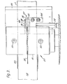
- Figure 2 is a similar but fragmentary view and on a larger scale than that of Figure 1;
- Figure 3 is a view taken along the line 3-3 of Figure 2, such being a side elevation;
- Figure 4 is a section taken along the line 4-4 of Figure 2;
- Figure 5 is a staggered section taken along the line 5-5 of Figure 2;
- Figure 6 shows two successive labels attached by a link in accordance with the present invention;
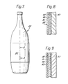
- Figure 7 is a view in side elevation of a container to which a label has been applied in accordance with the present invention;
- Figure 8 is a section taken along the line 8-8 of Figure 7 showing a limp plastic label directly adhered to the wall of a container;
- Figure 9 is a view similar to that of Figure 8 showing the limp plastic label adhered to a plastic backing material in accordance with the invention which, in turn, is adhered to the container.
- The scales of Figures 8 and 9 are exaggerated.
- Referring now to Figure 1, the machine is generally designated by the
reference numeral 10, and the label stock by thereference numeral 11, which is drawn from a roll of label stock (not shown) and passes between adriving roller 12 and a driven roller 13 to acutting instrumentality 14. Label stock is of the limp variety described above. Each label (indicated at 15) is supplied to a rotatingvacuum drum 16, glue being applied to the exposed surface of the label on the drum by a glue wheel 17. This glue or adhesive application may be limited to the leading end and the trailing end of the label, or it may be applied to the entire perimeter of the label in what is called a "picture frame" pattern, or it may be applied to the entire surface of the label. A container guide is shown at 18 forcontainers 19 which are supplied by astar wheel 20 havingpockets 21. The star wheel supplies the containers to the vacuum drum at a label applying station. Acurved container guide 25 is provided which is concentric to the drum and is spaced therefrom a distance such that, as the containers pass between this guide and the drum, a moderate but sufficient pressure is applied to cause the containers to spin about their own axes as well as to travel concentrically to and in contact with the label drum. Each container, in turn, will contact the glued leading end of the label, and as the container is caused to spin the label is wrapped around it. The extent of theguide 25 will be such as to accomplish an appropriate wrap. Thus if the label is wrapped entirely around a container, theguide 25 will be of a length such as to accomplish this, whereas if the label is only a partial label, that is to say, if it is applied to only a portion of the circumference of the container, theguide 25 may be shorter. - It will be apparent to those skilled in the art that appropriate means is provided to operate a glue wheel and other instrumentalities which are not an essential part of the particular features of the present invention, and that such may be varied in accordance with known skill of the art. The containers may be glass, metal, plasticpaperboard, etc., and they may be round or of other shape. Other types of container feed, e.g., a screw-type feed may be used. The container feed may be continuous or intermittent.
- Referring now to Figures 2, 3 and 4, a
label guide 27 is provided in advance of thecutting instrumentality 14. It comprises aright angle bracket 28 bolted to the frame of the machine whose upright leg (see Figure 4) is secured, for example by welding, to aguide plate 29 which, in turn, is bolted to asecond guide plate 30 bybolts 31, aspacer 32 being used to space theplates second angle bracket 34 is also secured to theplate 29 and at itsupper end 35 it is bolted to aplate 36. The inner (right-hand as viewed in Figure 4) end of thepart 35 is recessed at 37 to receive alabel support member 38 which is clamped betweenparts bolts 39. Thesupport member 38 is received in aslit 40 formed inplate 29 and is flush with theplate 29 and therefore contacts the label stock as it passes through theguide 27. - The
cutting instrumentality 14 comprises arotary cutter member 41 and astationary cutter member 42. The stationary cutter member may, however, be retractable for a purpose explained hereinafter. An example of a suitable, retractable stationary cutter member is shown in our U.S. Patent No. 4,108,710. - A sector of the
rotary cutter member 41 is cut away at 43 and within this sector ablade 44 is bolted bybolts 46 and aplate 47 to the face 48 of the sector. Thestationary cutter 42 is mounted on aframe bracket 49. Adjustment of theblade 44 may be accomplished by means ofscrews 55 threaded intoholes 56 formed in the rotary cutter member. As will be seen in Figure 5, theblade 44 is formed withslots 57 which receive thescrews 46. By loosening thescrews 46 and adjusting thescrews 55, the cutting edge 44a of theblade 44 can be adjusted in relation to the stationary member, after which thescrews 46 are tightened. - Further, as shown in Figure 5,
blade 44 is formed at its mid-portion with aslot 58 in which thesupport member 38 is received. As a result of this configuration, the leading label is not completely severed from the next label. Instead, alink 59 remains connecting it to the next label, the purpose of which is explained hereinafter, (see Figure 6). - Label material, after passing through
cutter 14 remains supported bysupport member 38 and it passes through achannel guide 65 which is supported bybracket 67 adjustably mounted byscrews 68 onframe bracket 49. An air jet device is provided at 69 alongside thechannel guide 65 to apply a jet of air to the label and hold it flat against the web or mid-portion of thechannel guide 65 until it is very close to the vacuum drum. - By this means the limp plastic label stock referred to hereinabove is given adequate support to prevent bending, buckling and other deformation. Therefore, the label material is delivered accurately and in flat condition to the
label drum 16. Further, as noted above, when a label is partially severed by theblade 44 it remains linked to the next label bylink 59 which as yet has been unsevered. The peripheral linear speed of the vacuum drum is slightly greater than the linear speed of the label stock as it is fed to thecutter 44. Therefore, when the vacuum drum grips the leading end of the label, a pull is exerted which accomplishes two useful functions. First, this pull or tension straightens out the label and prevents deformation which would interfere with proper operation of the machine and with proper labelling. This is accomplished before tension on thelink 59 is sufficient to rupture it. Then the link, being small, is ruptured by the tension so that it is completely separated from the next label. - The glue wheel 17 may apply glue only to the leading end and the trailing end of the label; or it may apply glue to the entire periphery of the label in a picture frame pattern; or it may apply glue to the entire surface of the label. The glue may be applied as a continuous film, or it may be applied in the form of small dots separated from one another but sufficient to adhere the label securely to the container. The glue is preferably a hot melt glue. Appropriate glue wheels and their mode of operation are well known in the art. It is advantageous to apply glue to the leading end of the label (and to the sides of the label where a picture frame pattern is applied) in the form of spaced dots when the container is to be recycled. This is so because such spot glueing applies a minimum of glue to the container itself and minimizes contamination of the containers when they are recycled.
- As will be seen in Figures 1 and 2, the
vacuum drum 15 haspads 75 to which vacuum is applied to grip and hold labels until the vacuum is terminated. The label is then released to a container at the label applying station. A suction passage is shown at 76 for this purpose, there being others as required. Operation of such vacuum means is well known in the art. The leading end of each pad is tapered at 77, followed by a raised portion orland 78 and a trailing portion of lesser radius than the land which is circular in shape, such portion being indicated by thereference numeral 79. The length of the pad is such in relation to the length of the label that the label slightly overhangs the trailing end of the pad. The purpose of the taper at 77 of the overhang is as follows: the taper serves to draw the leading end of the label inwardly by reason of suction and out of contact with the glue wheel, whereby the normal tendency of the label to adhere to and to follow the glue wheel is avoided. The resulting set back of the glue application to the leading end of the label is small enough that when pressure is applied to the label by the curvedconcentric guide 25 and thedrum 16 the glue will spread to the edge of the label and a good bond will-result. The purpose of the overhang is to prevent glue from being applied to the surface of the label drum between the pads. The purpose of theland 78 is to prevent glue from being applied to the portion of the pad rearwardly of the land. (If it is desired to apply glue to the entire surface of the label there will be no such lands). - Reverting to the
label guide 27, thecutter 14 and theguide 65 and thejet device 69, these elements cooperate to keep the limp label material flat so that it is cut properly at the cutting station and is fed in flat configuration to the label drum. This is assisted by the fact that each label, as it is partially severed, remains connected to the next label by theaforesaid link 59 and by the fact that the peripheral speed of thedrum 16 is slightly greater than the rate of feed of the label material. When the label feed is stopped, for example because there is a gap in the supply of containers (which may be sensed, for example, by a photocell) the vacuum drum will continue rotating and so will therotary cutting member 41. Thestationary cutter 42 will be retracted, for example by means such as described in our U.S. Patent No. 4,108,710. This is timed to occur so that the end of the label is very close to, in fact it may be touching, the surface of thedrum 16 and projects outwardly from thechannel guide 65. The extent of this projection, however, is not such as to allow the projecting label to bend. Continued operation of theair jet device 69 also assists in keeping the label from bending. Therefore, when operation is resumed and thefeed rollers 12 and 13 push the label material through theguide 27 and the cutting station and to thechannel guide 65 deformation of the label is prevented. Before any such deformation can occur to an extent that it is bothersome, the leading end of the label will be gripped by the label drum. - An added advantage of the
support member 38 is that it inhibits the normal tendency of the label material to follow theblade 44. Plastic material tends to accumulate a considerable electrostatic charge which will cause it to cling to a metal surface or other solid surfaces. Thesupport member 38 prevents this from occurring. - Referring now to Figure 7, a container is shown which is generally designated by the
reference numeral 85. The container may have any of various shapes, and it may be made of a variety of materials, as noted above. An increasingly popular material is PET, especially for liquids such as soft drink beverages, which are refrigerated and are exposed to moisture. Thelabel 86 shown applied to the container may be a full wrap label or a partial wrap label and it may be adhered to the container by a dot pattern of glue at the leading end (which will, of course, be spread by pressure during label application) and a line of glue at the trailing end overlapping the leading end. The glue pattern may be a picture frame pattern or it may be applied to the entire surface of the label. - Referring to Figure 8, the material of the container is shown at 87, a layer of adhesive at 88, and a limp label at 89, and printing at 90. As noted above, the
adhesive layer 88 may exist only at the leading edge of the label and the overlap at the trailing end of the label, or it may be applied in a picture frame pattern, or it may be applied to the entire surface of the label. - Referring now to Figure 9, the material of the container is shown at 87 and an adhesive layer at 88 (which may be applied as described above). Also shown is the limp
plastic material 89. Between theplastic material 89 and theadhesive layer 88 is a layer ofpolyethylene 91 which is laminated at 92 to thelimp label material 89. Either the polyethylene or the limp plastic material may bear printing (not shown). This label material is supplied in laminated form. This provides an alternative to the plastic/special paper laminate described above. The plastic-on-plastic laminate is advantageous because it avoids the need for special paper, it is water resistant, and white, opaque polyethylene may be selected so as to be printed or it may be clear. Nevertheless, the plastic-on-plastic laminate is limp, and requires, or benefits from the mechanical mode of operation of the present invention. - It will therefore be apparent that novel apparatus and method are provided for applying limp label material to containers, and that a novel labelled container is also provided. Although the invention has been described with reference to labelling containers, it may be used to apply limp film material generally to articles other than containers. It will also be apparent that other types of cutting instrumentalities may be used, for example a rotary die cutter such as described in Dickey U.S. Patent Application Serial No. 871,554, entitled "Rotary Die Cutting Assembly for Cutting Labels", filed January 23, 1978, now U.S. Patent No. 4188843 , in which when the label feed is terminated, for example because of a void in the container line, the anvil roller is retracted and carries with it the label material.
Claims (22)
1. Apparatus for severing a continuous length of film material (11) into segments comprising a cutting instrumentality (44,42) acting to sever such segments from the leading end of such length of film as it is supplied to the cutting instrumentality and tensioning means (16) acting to pull the leading end of each severed segment from the cutting instrumentality, characterised in that said cutting instrumentality is arranged to act to partially sever each segment and to leave a connecting link to the next, unsevered segment, in use such link being ruptured and the partially severed segment (15) being completely separated by tension exerted by such tensioning means (16).
2. The apparatus of Claim 1, characterised in that the tensioning means is a rotary vacuum drum (16).
3. The apparatus of Claim 2, characterised in that the cutting instrumentality is a rotary cutter having a rotating blade (44), such blade being formed with a slit in its cutting edge which results in forming said link.
4. A labelling machine including a label feed acting to pull continuous label stock (11) from a roll thereof and to feed such label stock forwardly to a label cutting station, a label cutter (42,44) at such station including a movable cutter member (44) acting to sever the label stock into segments (15) of the required length, and a rotary label applicator acting to grip the leading end of each label after it passes through the cutting station and to apply the label (15) to an article, characterised in that a cutting blade is provided which is carried by said movable cutting member, and is formed with a slit, the blade being arranged to sever a label (15) and the slit being arranged to interrupt the resulting cut and to leave a small link between the partially severed label (15) and the next label, said label applicator (16) being arranged to pull and apply tension to the leading end of the partially severed label (15) and to rupture the link.
5. A machine according to Claim 4, characterised in that the movable cutting member is a rotary member (44) which cuts a label during each revolution, and said label applicator is a rotary vacuum drum (16).
6. A machine according to Claim 5, characterised in that the slit is at a mid-portion of the blade and a support member is provided which is located within said slit and extends forwardly from the cutting station and acts to maintain the label (15) in flat configuration.
7. A labelling machine according to Claim 6, characterised by a mechanical guide for the label (15) between the cutting station and the vacuum drum (16), such guide acting to hold the label in a flat configuration.
8. A labelling machine according to Claim 7, characterised by air jet means cooperating with the mechanical guide to hold the label (15) in a flat configuration.
9. A labelling machine according to Claim 8, characterised in that said mechanical guide is in the form of a channel and the air jet means acts to hold the label (15) against the bottom of the channel.
10. A method of severing a continuous length of film material (11) into segments (15), which is characterised in that it comprises providing a cutting instrumentality (44,42) which functions to partially sever segments from the leading end of the film material as it is fed to the cutting instrumentality and to leave a small, easily ruptured link between each partially severed segment (15), and the next unsevered segment, and thereafter exerting a pull on the leading end of the film material, sufficient to rupture such link.
11. A method according to Claim 10, characterised in that the film material is limp and prone to be deformed and said tensioning acts also to maintain the film in a flat configuration.
12. A method according to Claim 11, characterised in that each partially severed segment is gripped by a rotary vacuum transport mechanism (16) which operates at a peripheral speed greater than the forward feed of film material to the cutting instrumentality and by reason thereof exerts such tension and ruptures the link.
13. A method of processing limp, easily deformed labels which comprises providing a continuous length of such label stock and providing also a cutting instrumentality and a label transport and feeding such continuous length of label to the cutting instrumentality characterised by partially severing a label while leaving a small, easily ruptured link between each partially severed label and the next label, then supplying the leading end of each partially severed label to the label transport and operating the latter at a speed such that it exerts a pull and tension on the link sufficient to rupture it.
14. The method of Claim 13, characterised in that the label transport is in the form of a rotary vacuum drum which grips each label in turn by suction, and which rotates at a peripheral speed greater than the speed of feed of label material to the cutting instrumentality, thereby exerting such pull and tension.
15. A method of applying limp, easily deformed labels to containers which comprises providing a label feed for supplying label material from a roll thereof, and providing also a cutting instrumentality for receiving label material as supplied by the label feed characterised by partially severing the label from the leading end of the label material while leaving a small, easily ruptured link between each partially severed label and the next label, supplying each partially severed label to a vacuum drum, rotating the vacuum drum at a peripheral speed sufficiently greater than the forward speed of the label material to rupture the link, and then applying each completely severed label to a container.
16. A labelled container comprising a container and a label of limp, easily deformed material adhered thereto by an adhesive.
17. The labelled container of Claim 16, characterised in that the label is of plastic material.
18. The labelled container of Claim 17, characterised in that the plastic is polypropylene.
19. The labelled container of Claim 18, characterised in that the polypropylene is directly adhesively adhered to the container.
20. The labelled container of Claim 18, characterised in that the polypropylene is laminated to a plastic backing which, in turn, is directly and adhesively secured to the container.
21. The labelled container of Claim 20, characterised in that the plastic backing is polyethylene.
22. A container provided with a label using a labelling machine according to any one of claims 4 to 9 or the method of claim 15.
Applications Claiming Priority (2)
| Application Number | Priority Date | Filing Date | Title |
|---|---|---|---|
| US7228879A | 1979-09-04 | 1979-09-04 | |
| US72288 | 1979-09-04 |
Publications (1)
| Publication Number | Publication Date |
|---|---|
| EP0025332A1 true EP0025332A1 (en) | 1981-03-18 |
Family
ID=22106673
Family Applications (1)
| Application Number | Title | Priority Date | Filing Date |
|---|---|---|---|
| EP80303040A Withdrawn EP0025332A1 (en) | 1979-09-04 | 1980-09-01 | Labelling machine and method, apparatus and method of severing film for use therein and container labelled thereby |
Country Status (3)
| Country | Link |
|---|---|
| EP (1) | EP0025332A1 (en) |
| JP (1) | JPS5641133A (en) |
| ES (1) | ES8105666A1 (en) |
Cited By (10)
| Publication number | Priority date | Publication date | Assignee | Title |
|---|---|---|---|---|
| FR2555548A1 (en) * | 1983-11-28 | 1985-05-31 | Owens Illinois Inc | APPARATUS AND METHOD FOR WINDING A PLASTIC LABEL AROUND A CONTAINER |
| EP0143621A2 (en) * | 1983-11-28 | 1985-06-05 | Owens-Illinois Plastic Products Inc. | Method of applying plastics labels |
| EP0145383A2 (en) * | 1983-11-28 | 1985-06-19 | Owens-Illinois Plastic Products Inc. | Method of applying solid plastics labels |
| EP0675806A1 (en) * | 1992-12-18 | 1995-10-11 | B & H MANUFACTURING COMPANY, INC. | Method of labeling articles having convex surfaces |
| WO2008049593A1 (en) * | 2006-10-27 | 2008-05-02 | Khs Ag | Cutting unit for a labelling device, and labelling device having a cutting unit of this type |
| WO2011012925A1 (en) * | 2009-07-29 | 2011-02-03 | Sidel S.P.A. | Cutting unit for labelling machines with a multiple-blade rotary drum |
| ITTO20111237A1 (en) * | 2011-12-29 | 2013-06-30 | Sidel Spa Con Socio Unico | CUTTING UNIT FOR REEL-POWERED LABELING MACHINES |
| CN113165765A (en) * | 2018-11-08 | 2021-07-23 | Khs有限责任公司 | Cutting mechanism for a labelling machine and labelling machine with such a cutting mechanism |
| EP3142933B1 (en) | 2014-05-15 | 2022-01-05 | P.E. Labellers S.p.A. | Labeling machine |
| EP3988462A1 (en) * | 2020-10-20 | 2022-04-27 | Sidel Participations | Labelling machine and method for applying labels onto articles adapted to contain a pourable product |
Families Citing this family (4)
| Publication number | Priority date | Publication date | Assignee | Title |
|---|---|---|---|---|
| JPS618508U (en) * | 1984-06-21 | 1986-01-18 | 渋谷工業株式会社 | Labeler with container orientation control device |
| US4662965A (en) * | 1985-12-18 | 1987-05-05 | Owens-Illinois, Inc. | Adhering heat sensitive labels to containers with hot melt adhesives |
| US4724036A (en) * | 1986-02-21 | 1988-02-09 | Owens-Illinois Plastic Products Inc. | Progressively ported vacuum drum for labeling machines |
| WO2013035401A1 (en) * | 2011-09-09 | 2013-03-14 | 株式会社フジシールインターナショナル | Label-gluing device |
Citations (6)
| Publication number | Priority date | Publication date | Assignee | Title |
|---|---|---|---|---|
| US3178329A (en) * | 1960-03-07 | 1965-04-13 | Lowenbrau Munchen | Methods of applying labels to bottles and apparatus therefor |
| GB1104234A (en) * | 1965-02-26 | 1968-02-21 | Enzo Seragnoli | A method of and mechanism for feeding sheet material to a wrapping machine |
| GB1109178A (en) * | 1964-09-23 | 1968-04-10 | Desmond Walter Molins | Improvements in or relating to apparatus for separating lengths of material from a continuous web |
| FR1571669A (en) * | 1967-06-22 | 1969-06-20 | ||
| US4108711A (en) * | 1977-02-23 | 1978-08-22 | B & H Manufacturing Company, Inc. | Label feed |
| FR2415047A1 (en) * | 1978-01-23 | 1979-08-17 | B & J Mfg Co | LABELING MACHINE CUTTING LABELS AND GLUING THEM ON VARIABLE SHAPED CONTAINERS |
-
1980
- 1980-09-01 EP EP80303040A patent/EP0025332A1/en not_active Withdrawn
- 1980-09-03 JP JP12127280A patent/JPS5641133A/en active Pending
- 1980-09-03 ES ES494743A patent/ES8105666A1/en not_active Expired
Patent Citations (6)
| Publication number | Priority date | Publication date | Assignee | Title |
|---|---|---|---|---|
| US3178329A (en) * | 1960-03-07 | 1965-04-13 | Lowenbrau Munchen | Methods of applying labels to bottles and apparatus therefor |
| GB1109178A (en) * | 1964-09-23 | 1968-04-10 | Desmond Walter Molins | Improvements in or relating to apparatus for separating lengths of material from a continuous web |
| GB1104234A (en) * | 1965-02-26 | 1968-02-21 | Enzo Seragnoli | A method of and mechanism for feeding sheet material to a wrapping machine |
| FR1571669A (en) * | 1967-06-22 | 1969-06-20 | ||
| US4108711A (en) * | 1977-02-23 | 1978-08-22 | B & H Manufacturing Company, Inc. | Label feed |
| FR2415047A1 (en) * | 1978-01-23 | 1979-08-17 | B & J Mfg Co | LABELING MACHINE CUTTING LABELS AND GLUING THEM ON VARIABLE SHAPED CONTAINERS |
Cited By (23)
| Publication number | Priority date | Publication date | Assignee | Title |
|---|---|---|---|---|
| FR2555548A1 (en) * | 1983-11-28 | 1985-05-31 | Owens Illinois Inc | APPARATUS AND METHOD FOR WINDING A PLASTIC LABEL AROUND A CONTAINER |
| EP0143621A2 (en) * | 1983-11-28 | 1985-06-05 | Owens-Illinois Plastic Products Inc. | Method of applying plastics labels |
| EP0144198A2 (en) * | 1983-11-28 | 1985-06-12 | Owens-Illinois Plastic Products Inc. | Improvements in or relating to apparatus and methods for wrapping plastics labels around containers |
| EP0145383A2 (en) * | 1983-11-28 | 1985-06-19 | Owens-Illinois Plastic Products Inc. | Method of applying solid plastics labels |
| GB2150107A (en) * | 1983-11-28 | 1985-06-26 | Owens Illinois Inc | Wrapping plastics labels around containers |
| GB2174676A (en) * | 1983-11-28 | 1986-11-12 | Owens Illinois Inc | Wrapping foamed polystyrene labels around containers |
| EP0144198A3 (en) * | 1983-11-28 | 1987-09-02 | Owens-Illinois, Inc. | Improvements in or relating to apparatus and methods for wrapping plastics labels around containers and labels therefor |
| EP0145383B1 (en) * | 1983-11-28 | 1990-07-11 | Owens-Illinois Plastic Products Inc. | Method of applying solid plastics labels |
| EP0143621B1 (en) * | 1983-11-28 | 1990-07-11 | Owens-Illinois Plastic Products Inc. | Method of applying plastics labels |
| EP0675806B1 (en) * | 1992-12-18 | 2001-02-28 | B & H MANUFACTURING COMPANY, INC. | Method of labeling articles having convex surfaces |
| EP0675806A1 (en) * | 1992-12-18 | 1995-10-11 | B & H MANUFACTURING COMPANY, INC. | Method of labeling articles having convex surfaces |
| WO2008049593A1 (en) * | 2006-10-27 | 2008-05-02 | Khs Ag | Cutting unit for a labelling device, and labelling device having a cutting unit of this type |
| CN101600624B (en) * | 2006-10-27 | 2012-04-11 | Khs有限责任公司 | Cutting unit for a labelling device, and labelling device having a cutting unit of this type |
| US9120588B2 (en) | 2006-10-27 | 2015-09-01 | Khs Gmbh | Beverage bottle or container labeling device with a cutting unit and cutting unit for a beverage bottle or container labeling device |
| CN102574599B (en) * | 2009-07-29 | 2014-03-12 | 西得乐公开有限公司 | Cutting unit for labelling machines with multiple-blade rotary drum |
| WO2011012925A1 (en) * | 2009-07-29 | 2011-02-03 | Sidel S.P.A. | Cutting unit for labelling machines with a multiple-blade rotary drum |
| CN102574599A (en) * | 2009-07-29 | 2012-07-11 | 西得乐公开有限公司 | Cutting unit for labelling machines with a multiple-blade rotary drum |
| EP2610190A1 (en) * | 2011-12-29 | 2013-07-03 | Sidel S.p.a. Con Socio Unico | Cutting unit for roll-fed labelling machines |
| ITTO20111237A1 (en) * | 2011-12-29 | 2013-06-30 | Sidel Spa Con Socio Unico | CUTTING UNIT FOR REEL-POWERED LABELING MACHINES |
| EP3142933B1 (en) | 2014-05-15 | 2022-01-05 | P.E. Labellers S.p.A. | Labeling machine |
| CN113165765A (en) * | 2018-11-08 | 2021-07-23 | Khs有限责任公司 | Cutting mechanism for a labelling machine and labelling machine with such a cutting mechanism |
| CN113165765B (en) * | 2018-11-08 | 2023-08-29 | Khs有限责任公司 | Cutting mechanism of labelling machine set and labelling machine set with same |
| EP3988462A1 (en) * | 2020-10-20 | 2022-04-27 | Sidel Participations | Labelling machine and method for applying labels onto articles adapted to contain a pourable product |
Also Published As
| Publication number | Publication date |
|---|---|
| JPS5641133A (en) | 1981-04-17 |
| ES494743A0 (en) | 1981-06-16 |
| ES8105666A1 (en) | 1981-06-16 |
Similar Documents
| Publication | Publication Date | Title |
|---|---|---|
| US6431241B1 (en) | Roll-fed labelling apparatus | |
| EP0025332A1 (en) | Labelling machine and method, apparatus and method of severing film for use therein and container labelled thereby | |
| EP0144198B1 (en) | Improvements in or relating to apparatus and methods for wrapping plastics labels around containers | |
| AU618047B2 (en) | Method of producing blocks of self-adhesive labels or the like and of applying the labels to a body | |
| US4336095A (en) | Machine for labeling bodies and shoulders of containers | |
| CA1128475A (en) | Method and apparatus for automatically labelling containers | |
| EP0577241B1 (en) | Method and apparatus for handling linerless label material | |
| JP3602786B2 (en) | Label sticking method and label sticking device | |
| EP0179575B1 (en) | Apparatus for producing labels | |
| US5458729A (en) | Apparatus and method for applying labels onto small cylindrical articles using improved film feed and cutting system | |
| CA1075643A (en) | Label feed | |
| US5369936A (en) | Apparatus and method for securing a detachable promotional banner or coupon to a flexible package | |
| CA2074921C (en) | Cylindrical body label wrapping system with cam operated adjustable path length retractable heaters | |
| US20030010433A1 (en) | Container and label combination | |
| US20040055260A1 (en) | Compact form - fill - seal machine | |
| CA1094941A (en) | Rotary die cutting assembly for cutting labels | |
| US4108706A (en) | Labelling machine | |
| US3553049A (en) | Method of and apparatus for applying labels to bottles | |
| EP1028895B1 (en) | Adhesive station and labeling machine | |
| US4390577A (en) | Composite label web | |
| NZ217648A (en) | Apparatus for applying heat activatable adhesive labels to containers | |
| WO2001000492A1 (en) | Labelling apparatus | |
| US6045616A (en) | Adhesive station and labeling machine | |
| GB2328427A (en) | Labelling with labels cut from non-backed strip | |
| US3707424A (en) | Adjustable label form slitter for addressing machines |
Legal Events
| Date | Code | Title | Description |
|---|---|---|---|
| PUAI | Public reference made under article 153(3) epc to a published international application that has entered the european phase |
Free format text: ORIGINAL CODE: 0009012 |
|
| AK | Designated contracting states |
Designated state(s): DE FR GB IT |
|
| STAA | Information on the status of an ep patent application or granted ep patent |
Free format text: STATUS: THE APPLICATION IS DEEMED TO BE WITHDRAWN |
|
| 18D | Application deemed to be withdrawn |
Effective date: 19820222 |
|
| RIN1 | Information on inventor provided before grant (corrected) |
Inventor name: HOFFMANN, WOLFGANG |