EP0025728A1 - Device for coupling a light source with divergent radiation to an optical fibre and method for the realisation of such a device - Google Patents
Device for coupling a light source with divergent radiation to an optical fibre and method for the realisation of such a device Download PDFInfo
- Publication number
- EP0025728A1 EP0025728A1 EP80401187A EP80401187A EP0025728A1 EP 0025728 A1 EP0025728 A1 EP 0025728A1 EP 80401187 A EP80401187 A EP 80401187A EP 80401187 A EP80401187 A EP 80401187A EP 0025728 A1 EP0025728 A1 EP 0025728A1
- Authority
- EP
- European Patent Office
- Prior art keywords
- fiber
- lens
- coupling device
- glass
- coupling
- Prior art date
- Legal status (The legal status is an assumption and is not a legal conclusion. Google has not performed a legal analysis and makes no representation as to the accuracy of the status listed.)
- Ceased
Links
Images
Classifications
-
- G—PHYSICS
- G02—OPTICS
- G02B—OPTICAL ELEMENTS, SYSTEMS OR APPARATUS
- G02B6/00—Light guides; Structural details of arrangements comprising light guides and other optical elements, e.g. couplings
- G02B6/24—Coupling light guides
- G02B6/255—Splicing of light guides, e.g. by fusion or bonding
- G02B6/2552—Splicing of light guides, e.g. by fusion or bonding reshaping or reforming of light guides for coupling using thermal heating, e.g. tapering, forming of a lens on light guide ends
-
- G—PHYSICS
- G02—OPTICS
- G02B—OPTICAL ELEMENTS, SYSTEMS OR APPARATUS
- G02B6/00—Light guides; Structural details of arrangements comprising light guides and other optical elements, e.g. couplings
- G02B6/24—Coupling light guides
- G02B6/42—Coupling light guides with opto-electronic elements
- G02B6/4201—Packages, e.g. shape, construction, internal or external details
- G02B6/4202—Packages, e.g. shape, construction, internal or external details for coupling an active element with fibres without intermediate optical elements, e.g. fibres with plane ends, fibres with shaped ends, bundles
- G02B6/4203—Optical features
Abstract
Description
L'invention concerne un dispositif de couplage entre une source de lumière émettant un rayonnement divergent et une fibre optique.The invention relates to a device for coupling between a light source emitting divergent radiation and an optical fiber.
Le problème du couplage entre une source à rayonnement divergent, notamment un laser semi-conducteur a été étudié dans le but d'augmenter la fraction de rayonnement captée par la fibre. Le couplage direct, dans lequel la source et la fibre sont simplement placés face à face sans élément optique intermédiaire, a une efficacité très mauvaise en raison des faibles dimensions de la fibre et de l'ouverture, généralement grande, du faisceau laser. Il a été étudié des configurations optiques diverses à base de cônes, de lentilles cylindriques, hémicylindriques ou sphériques, de lentilles hémisphériques. Les études théoriques et pratiques montrent que l'on obtient des résultats particulièrement intéressants avec une lentille hémisphérique accolée à l'extrémité de la fibre. Différentes méthodes de fabrication ont été proposées. Parmi celles-ci, le thermoformage, qui consiste à faire fondre l'extrémité de la fibre à l'aide d'un moyen quelconque, a été décrit notamment dans "Applied Optics" Vol. 14, No 2, pages 294-298 et dans "Applied Optics" Vol. 14, No 12, pages 2815.2816. Du fait de la nature différente des matériaux formant le coeur et la gaine de la fibre, cette méthode ne permet pas d'obtenir de bonnes qualités optiques pour tous les types de fibres. Benson a d'ailleurs montré dans le deuxième article cité ci-dessus qu'on n'obtient des résultats intéressants que pour certaines valeurs du rapport entre le diamètre de coeur et le diamètre de gaine. D'autre part, cette technique nécessite souvent, surtout pour les fibres en silice couramment utilisées, des températures très élevées, donc un appareillage lourd. Une structure hétérogène a été décrite par Timmermann dans "Applied Optics" Vol. 15, No 10, pages 2432-2433. La gaine de la fibre est presque entièrement enlevée par attaque chimique et la lentille est obtenue par trempé dans un matériau à bas point de fusion : de l'époxy pour une fibre en verre, de l'époxy ou du verre pour une fibre en silice. Le verre n'est donc pas utilisable pour n'importe quelle fibre et la résine pose des problèmes de vieillissement.The problem of coupling between a divergent radiation source, in particular a semiconductor laser, has been studied with the aim of increasing the fraction of radiation picked up by the fiber. Direct coupling, in which the source and the fiber are simply placed face to face without an intermediate optical element, has very poor efficiency due to the small dimensions of the fiber and the generally large aperture of the laser beam. Various optical configurations based on cones, cylindrical, semi-cylindrical or spherical lenses, hemispherical lenses have been studied. Theoretical and practical studies show that particularly interesting results are obtained with a hemispherical lens attached to the end of the fiber. Different manufacturing methods have been proposed. Among these, thermoforming, which consists in melting the end of the fiber using any means, has been described in particular in "Applied Optics" Vol. 14,
La présente invention vise la réalisation d'une lentille plan-convexe en verre de haut indice sur n'importe quel type de fibre. La gaine de la fibre est maintenue intacte, ou bien est partiellement attaquée en vue de réduire son diamètre. Le choix du verre à bas point de fusion permet d'utiliser un appareillage simple. La bonne adhérence des jonctions verre-verre et verre- silice permet une bonne tenue mécanique et un bon vieillissement. Un indice élevé, supérieur à celui des matériaux constituant la fibre, permet d'obtenir un couplage optimum et des tolérances de positionnement laser-fibre facilement réalisables. Le diamètre de la lentille peut être choisi de façon à optimiser le rendement de couplage.The present invention relates to the production of a plano-convex lens of high index glass on any type of fiber. The fiber sheath is kept intact, or is partially attacked in order to reduce its diameter. The choice of glass with a low melting point allows the use of simple apparatus. The good adhesion of the glass-glass and glass-silica junctions allows good mechanical strength and good aging. A high index, higher than that of the materials constituting the fiber, makes it possible to obtain optimum coupling and easily achievable laser-fiber positioning tolerances. The diameter of the lens can be chosen so as to optimize the coupling efficiency.
L'invention a principalement pour objet un dispositif de couplage entre une source lumineuse à rayonnement divergent et une fibre optique, comprenant une lentille plan-convexe dont la face plane coïncide avec la face d'entrée de la fibre et a une section quasi-circulaire, caractérisé en ce que cette lentille est constituée d'un verre d'indice de réfraction supérieur et de température de fusion inférieure à ceux des matériaux constituant la fibre.The main object of the invention is a device for coupling between a light source with divergent radiation and an optical fiber, comprising a plano-convex lens whose planar face coincides with the entry face of the fiber and has a quasi-circular section. , characterized in that this lens consists of a glass with a higher refractive index and a lower melting temperature than that of the materials constituting the fiber.
D'autres caractéristiques et avantages de l'invention apparaitront au moyen de la description qui suit, en référence aux figures annexées :
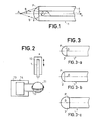
- - la figure 1 représente une fibre optique munie d'une lentille de couplage ;
- - la figure 2 représente schématiquement un appareil de réalisation de la lentille ;
- - la figure 3 représente trois formes de lentilles obtenues ;
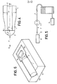
- - la figure 4 montre les paramètres nécessaires pour l'optimisation du couplage ;
- - la figure 5 représente un système de transmission optique ;
- - la figure 6 représente un support de positionnement du laser et de la fibre.
- - Figure 1 shows an optical fiber provided with a coupling lens;
- - Figure 2 schematically shows an apparatus for producing the lens;
- - Figure 3 shows three forms of lenses obtained;
- - Figure 4 shows the parameters necessary for the optimization of the coupling;
- - Figure 5 shows an optical transmission system;
- - Figure 6 shows a laser and fiber positioning support.
La figure 1 représente en coupe une fibre optique 1 munie d'une lentille de couplage 2 destinée à améliorer le couplage entre la fibre et une source lumineuse placée en un point A que l'on considère tout d'abord situé sur l'axe x de la figure 1. Selon l'invention, la lentille de couplage 2 est réalisée sur l'extrémité de la fibre 1 faisant face au point A et formant une surface plane P perpendiculaire à l'axe x. La source placée en A émettant un faisceau divergent 5 de demi-angle au sommet 6 , la lentille 2 fait converger ce faisceau vers la face d'entrée P. Seule une partie du faisceau remplit les conditions de propagation dans le coeur 3 de la fibre. On a représenté sur la figure l'un des rayons remplissant ces conditions. Celles-ci sont fonction du diamètre du coeur 3, de celui de la lentille 2, de son indice , et de l'ouverture numérique de la fibre 1. Si la fibre 1 est destinée à être connectée à une autre fibre d'ouverture numérique plus faible, c'est cette dernière qui est à prendre en compte pour les conditions de couplage proprement dites. L'amélioration du couplage, apportée par la lentille, consiste en une augmentation de la fraction de rayonnement couplée, dûe à la convergence opérée.FIG. 1 represents in section an
Pour réaliser l'association fibre-lentille représentée sur la figure 1, il faut tout d'abord obtenir une extrémité de fibre nette et dans le plan recherché. Une méthode préconisée consiste à opérer par cassure. On peut notamment effectuer cette cassure à l'aide d'un diamant présentant un fil très fin (de l'ordre du micron), ce qui permet d'obtenir un plan d'excellente qualité, la perturbation résultant de la trace dûe à l'attaque du diamant ayant une dimension négligeable devant les dimensions de la lentille à réaliser. Avant d'opérer la cassure, il a bien sûr fallu enlever l'enveloppe de protection de la fibre brute sur 1 cm environ. Les faces d'entrée et de sortie de la fibre ayant ainsi été préparées, on les nettoie par un procédé classique, à base de Décon.To make the fiber-lens association represented in FIG. 1, it is first of all necessary to obtain a clean fiber end and in the desired plane. One recommended method is to operate by breaking. We can in particular make this break using a diamond having a very fine wire (of the order of a micron), which makes it possible to obtain a plan of excellent quality, the disturbance resulting from the trace due to the attack of the diamond having a negligible dimension compared to the dimensions of the lens to be produced. Before breaking, it was of course necessary to remove the protective cover from the raw fiber for about 1 cm. The input and output faces of the fiber having thus been prepared, they are cleaned by a conventional process, based on Decon.
Selon l'invention, la lentille 2 est une lentille plan-convexe formant une calotte sphérique dont le centre O est situé sur l'axe x. Elle est formée dans un matériau transparent ayant un indice de réfraction n nettement supérieur à ceux du coeur 3 et de la gaine 4 de la fibre. Le choix d'un indice élevé sera justifié dans la suite de la description. On a démontré en effet et constaté expérimentalement que, quelque soit la source lumineuse à coupler, le coefficient de couplage est d'autant plus grand que l'indice n est élevé. Le choix du matériau à utiliser a été guidé par les propriétés d'adhérence, de tenue mécanique, et surtout par les valeurs d'indice de réfraction et de température de fusion. C'est ainsi que l'on est amené à choisir un verre plutôt qu'un plastique. Le choix du verre assure une certaine continuité structurelle entre la lentille et la fibre, qu'elle soit en verre ou en silice.According to the invention, the
La figure 2 montre les éléments principaux d'un dispositif permettant de déposer la calotte sphérique en verre sur l'extrémité préparée de la fibre 1. Celle-ci est maintenue et positionnée par un support mobile 10, de préférence dans une position verticale. Une goutte de verre en fusion 11 est retenue dans un filament chauffant 12 porté par un porte-filament 13 également mobile. La forme du filament est très importante car elle détermine la forme de la goutte de verre 11, qui dépend aussi de la pesanteur. L'axe x de la fibre doit être parfaitement centré par rapport au filament. Sa verticalité assure une symétrie de révolution. Lorsque les positionnements relatifs sont effectués, contrôlés au microscope, l'extrémité de la fibre 1 est mise en contact avec la goutte de verre 11, puis éloignée. Elle comporte avec elle une petite quantité de verre qui, du fait des tensions superficielles, se met sous la forme d'une calotte dont le centre est sur l'axe x, à condition que le positionnement ait été bien effectué à l'extrémité de la fibre. Après le dépôt, si la forme du ménisque ne correspond pas à la forme escomptée : par exemple, existence d'un méplat provenant du fait que la fibre a été retirée trop rapidement, ou hauteur du ménisque incorrecte, on peut toujours restituer l'opération pour corriger dans le sens voulu. Avant la mise en contact de la fibre avec le verre fondu, il est préférable de la maintenir au voisinage du filament chauffant pendant quelques secondes pour amener l'extrémité de la fibre à la même température que le verre, ce qui évite tout choc thermique qui détériorerait la fibre.Figure 2 shows the main elements of a device for depositing the spherical glass cap on the prepared end of the
La température du verre en fusion se situe entre l'état pateux et le début de la décomposition. Il est très important qu'elle soit inférieure à la température de ramollissement de la fibre. Basse température de fusion et indice élevé sont d'ailleurs souvent liés pour le verre. Ce fait permet d'éviter les inconvénients de la technique connue constituant à créer la calotte sphérique en faisant fondre le bout de la fibre : migration de matière vers l'extrémité, risquant d'entrainer poussières ou inhomogénéités, impossibilité d'obtenir un couplage optimal pour n'importe quelle fibre à cause de la nature différente des matériaux de coeur et de gaine. Le choix d'une basse température permet en outre d'utiliser un appareillage simple pour la mise en oeuvre du procédé.The temperature of the molten glass is between the pasty state and the start of decomposition. It is very important that it is lower than the softening temperature of the fiber. Low melting temperature and high index are often linked for glass. This fact avoids the disadvantages of the known technique of creating the spherical cap by melting the end of the fiber: migration of material towards the end, risking dust or inhomogeneities, impossibility of obtaining optimal coupling for any fiber due to the different nature of the core and cladding materials. Choosing a low temperature also allows the use of simple equipment for implementing the process.
Le procédé le l'invention a été essayé essentiellement avec trois types de verre dont les indices de réfraction pour une longueur d'onde de 8521 A et la température de transformation sont respectivement 1,88 - 396°, 1,60 - 432°C, 1,48 - 464°C. La température désirée est obtenue en réglant l'intensité de l'alimentation électrique 14 du filament. Les faibles valeurs de température nécessaires permettent d'utiliser avantageusement pour la réalisation de l'invention une microforge de Fonbrune, utilisée habituellement pour la fabrication de micro-outils. On peut utiliser pour le filament un matériau dont la température de fusion n'est pas très élevée. Le filament peut être, par exemple, en platine rhodié à 30% qui fond à 1910°.The process of the invention has been tried essentially with three types of glass whose refractive indices for a wavelength of 8521 A and the transformation temperature are respectively 1.88 - 396 °, 1.60 - 432 ° C , 1.48 - 464 ° C. The desired temperature is obtained by adjusting the intensity of the
La forme de la calotte sphérique, notamment la position de son centre, dépendent de paramètres contrôlables qui sont la température du verre en fusion, les vitesses d'approche et d'éloignement de la fibre par rapport au filament chauffant et les variations de température ainsi obtenues. La figure 3 représente 3 types de calottes pouvant être obtenus avec des conditions de dépôt différentes. Sur la figure 3a, la calotte est hémisphérique, c'est à dire que son centre O est situé dans la plan P. Sur la figure 3b, le centre O est situé à l'intérieur de la fibre. Sur la figure 3c, le centre O est situé entre le point A et l'extrémité de la fibre. La bonne reproductibilité du procédé peut permettre une automatisation des opérations, une fois déterminés les paramètres : température, vitesses de rapprochement et d'éloignement respectifs de la fibre et du filament chauffant.The shape of the spherical cap, in particular the position of its center, depend on controllable parameters which are the temperature of the molten glass, the speeds of approach and distance of the fiber compared to the heating filament and the temperature variations as well obtained. FIG. 3 represents 3 types of caps which can be obtained with different deposition conditions. In FIG. 3a, the cap is hemispherical, that is to say that its center O is located in the plane P. In FIG. 3b, the center O is located inside the fiber. In Figure 3c, the center O is located between point A and the end of the fiber. The good reproducibility of the process can allow automation of the operations, once the parameters have been determined: temperature, respective speeds of approach and distance of the fiber and the heating filament.
Ainsi qu'il a été dit, le procédé de l'invention permet d'obtenir n'importe quelle forme de lentille (position du centre, diamètre). Il permet donc l'optimisation du couplage, telle qu'on peut la déterminer par le calcul et la vérifier par l'expérience. Les paramètres nécessaires pour cette optimisation sont définis sur la figure 4 pour une lentille hémisphérique. Il s'agit du diamètre d du coeur, du rayon R de la demisphère, de la distance X + R entre le point A et le centre O, de l'indice n de la lentille et de l'ouverture numérique ON de la fibre. Le mode de calcul est voisin de celui détaillé par l'article de C.A.BRACKETT dans la revue "Journal of Applied Optics", vol 45, No 6, juin 1974, la seule différence étant que cet article se rapporte à la technique de fusion de l'extrémité de la fibre, si bien que l'indice de la lentille est sensiblement égal à celui du coeur de la fibre. L'optimisation est recherché, à titre d'exemple, pour une fibre de diamètre de coeur 50 m et une ouverture numérique de 0,18.As has been said, the method of the invention makes it possible to obtain any form of lens (position of the center, diameter). It therefore allows optimization of the coupling, as can be determined by calculation and verified by experience. The parameters necessary for this optimization are defined in FIG. 4 for a hemispherical lens. These are the diameter d of the core, the radius R of the hemisphere, the distance X + R between point A and the center O, the index n of the lens and the numerical aperture ON of the fiber . The method of calculation is similar to that detailed by the article by CABRACKETT in the journal "Journal of Applied Optics", vol 45,
D'autre part, on désire admettre des tolérances de positionnement de la source, par exemple + 0,1 pour ![]()
![]()
![]()
![]()
![]()
![]()
Lorsque l'on désire un diamètre de fibre inférieur au diamètre réel des fibres dont on dispose, on opère une réduction de diamètre à l'extrémité par attaque chimique dans une solution d'acide fluorhydrique. On utilise, par exemple, une solution à 40% et la gaine est attaquée sur environ 1 cm de longueur. L'opération peut se faire à température ambiante. On constate que l'acide fluorhydrique attaque en priorité le coeur de la fibre, si bien que, en l'absence de précautions particulières, la surface obtenue n'est pas plane mais constitue une lentille divergente, ce qui nuit au couplage. Pour éviter l'attaque du coeur, il est préférable de le protéger avec une cire que l'on enlève ensuite. La vitesse d'attaque de la gaine étant connue (environ 1 m par minute), on peut déterminer la durée nécessaire. Par ailleurs, un contrôle permanent du diamètre peut être effectué. Un fois le diamètre recherché atteint, la fibre est rincée, et c'est alors que l'on prépare son extrémité par cassure, comme indiqué plus haut.When a fiber diameter smaller than the actual diameter of the fibers available is desired, the diameter is reduced at the end by chemical attack in a solution of hydrofluoric acid. For example, a 40% solution is used and the sheath is attacked over about 1 cm in length. The operation can be done at room temperature. It is found that hydrofluoric acid attacks the core of the fiber as a priority, so that, in the absence of special precautions, the surface obtained is not planar but constitutes a divergent lens, which harms coupling. To avoid the attack of the heart, it is preferable to protect it with a wax that one then remove. The speed of attack of the sheath being known (approximately 1 m per minute), one can determine the duration necessary. In addition, a permanent control of the diameter can be carried out. Once the desired diameter is reached, the fiber is rinsed, and it is then that its end is prepared by breaking, as indicated above.
L'amélioration apportée par l'invention peut être évaluée par la mesure de l'atténuation de la puissance lumineuse émise par la source, à la sortie d'un système de transmission de la lumière bien caractérisé. En effet, le dispositif de couplage selon l'invention, est destiné à faire partir d'un système de transmission du type comprenant :
- - une source lumineuse, généralement un laser à semi-conducteur dont les caractéristiques sont connus, notamment son diagramme de rayonnement ;
- - une fibre optique de liaison, qui peut être longue de quelques mètres à plusieurs km, également connue, en particulier par son ouverture numérique et son atténuation en fonction du la longueur d'onde de la lumière qu'elle propage ;
- - le dispositif de couplage, introduit entre la source et la fibre, comprenant la
fibre 1, que l'on peut appeler fibre de référence, et qui mesure quelques cm, et la lentille plan-convexe 2, possédant les caractéristiques définies ci-dessus.
- - a light source, generally a semiconductor laser, the characteristics of which are known, in particular its radiation diagram;
- - an optical fiber link, which can be a few meters to several km long, also known, in particular by its digital aperture and its attenuation as a function of the wavelength of the light it propagates;
- - the coupling device, introduced between the source and the fiber, comprising
fiber 1, which can be called reference fiber, and which measures a few cm, and the plano-convex lens 2, having the characteristics defined above .
Un système de transmission typique, utilisable pour la mesure de l'atténuation, est représenté sur la figure 5. La source 6, est un laser GaAs/GaAlAs. Sa puissance en continu est égale à 2mW. Sa longueur d'onde est égale à 0,83/m. Son diagramme de rayonnement peut être caractérisé par la mesure de la puissance émise en fonction de l'angle d'émission, dans des plans parallèles et perpendiculaires à la jonction semi-conductrice. Etant donné la symétrie de révolution du dispositif de couplage, la caractéristique la plus intéressante est la puissance totale émise dans un cône de demi-angle au sommet e . D'après les résultats donnés précédemment, l'ouverture du faisceau couplé dans la fibre 1 est de l'ordre de sins=0,5. Pour cette valeur, la fraction de puissance couplée par rapport à la puissance disponible du laser PE est de l'ordre de 0,7. Le laser 6 est placé sur un support mobile en rotation selon un axe perpendiculaire au plan de la jonction, et mobile en translation selon trois axes perpendiculaires x, y, z. La fibre de liaison 7, est enroulée et mesure environ 600 m. Son atténuation vaut environ 2,6 dB/km, ce qui donne une atténuation totale de 1,56 dB et un coefficient de transmission de 0,7. Son ouverture numérique est égale à 0,18.A typical transmission system, usable for measuring the attenuation, is shown in FIG. 5. The
Le dispositif de couplage à tester, c'est à dire la fibre intermédiaire 1 munie de la lentille 2, est fixée, en amont, sur un support mobile en rotation suivant un axe perpendiculaire à celui de la fibre et à l'axe de rotation du support du laser. Elle est fixée, en aval, sur un support permettant son couplage avec la fibre de liaison 7. L'extrémité de celle-ci est rendue mobile en translation et rotation pour assurer l'optimisation de la connexion 17 entre les deux fibres. Celle-ci s'effectue avec de la glycérine comme liquide adaptateur d'indice. La sortie de la fibre 7 est positionnée devant un photodétecteur 8, la connexion s'effectuant également dans un liquide adaptateur d'indice. Le signal de sortie du détecteur permet de mesurer la puissance lumineuse transmise PS, Pour le réglage des différents positionnements, on recherche un maximum de puissance de sortie PS. On effectue ainsi les réglages de la connexion fibre 1-fibre 7 du couplage laser 6-fibre 1. La puissance délivrée par le laser 6, PE étant contrôlée pour être toujours égale à 2mW, on mesure le rapport ![]()
![]()
![]()
- - sans réduction de diamètre : X = 46µm,

- - avec réduction de diamètre (2R = 91 µm) : X = 35/µm,


lentille 2d'indice 1,88 apporte donc un gain de 4dB sans réduction du diamètre de la fibre et de 4,7 dB avec un diamètre de fibre optimisé.
- - without reduction in diameter: X = 46µm,
- - with diameter reduction (2R = 91 µm): X = 35 / µm,
lens 2 of index 1.88 therefore provides a gain of 4 dB without reduction of the fiber diameter and of 4.7 dB with an optimized fiber diameter.
Lorsque la lentille de couplage est proche du laser, ce qui est le cas d'après les résultats précédents, une partie de la lumière se réfléchit sur la face convexe de la lentille et n'est pas récupérée dans la fibre. Pour remédier à cet inconvénient, on peut déposer sur cette face une couche diélectrique dont l'indice soit voisin de ![]()
![]()
![]()
![]()
Un exemple de support de positionnement permettant d'atteindre les valeurs de tolérance indiquées est représenté sur la figure 6. Il s'agit d'un socle de cuivre 51 dans lequel a été réalisée une rainure 52 en forme de V. Pour obtenir des flancs plans ayant une inclinaison très précise, il est avantageux d'utiliser le procédé dé crit dans la demande de brevet français déposée par la demanderesse le 18 Mai 1978 sous le N « 78 14 763 et publié sous le N° 2 426 271. En effet, selon ce procédé, la rainure 52 reproduit en négatif un dièdre formé par attaque chimique de silicium monocristallin, attaque qui s'effectue préférentiellement suivant des axes du cristal. En même temps que la rainure 52, est réalisée une empreinte 53 formant une zone plane destinée à servir d'assise au laser semi-conducteur. Celui-ci est soudé sur cette zone 53 du socle, de telle façon que ses couches successives soient parallèles au plan. La fibre optique 1 préparée et réalisée selon la méthode décrite ci-dessus, est placée dans la rainure 52. L'empreinte 53 et la rainure 52 sont prévues en fonction de la structure de la plaquette laser et du diamètre de la fibre de façon que la couche active du laser soit dans le plan diamétral de la fibre.An example of a positioning support enabling the indicated tolerance values to be reached is shown in FIG. 6. It is a copper base 51 in which a V-shaped
Claims (13)
Applications Claiming Priority (2)
| Application Number | Priority Date | Filing Date | Title |
|---|---|---|---|
| FR7922886 | 1979-09-13 | ||
| FR7922886A FR2465238A1 (en) | 1979-09-13 | 1979-09-13 | DEVICE FOR COUPLING BETWEEN A DIVERGENT RADIATION LIGHT SOURCE AND AN OPTICAL FIBER AND A METHOD OF MAKING SUCH A DEVICE |
Publications (1)
| Publication Number | Publication Date |
|---|---|
| EP0025728A1 true EP0025728A1 (en) | 1981-03-25 |
Family
ID=9229623
Family Applications (1)
| Application Number | Title | Priority Date | Filing Date |
|---|---|---|---|
| EP80401187A Ceased EP0025728A1 (en) | 1979-09-13 | 1980-08-13 | Device for coupling a light source with divergent radiation to an optical fibre and method for the realisation of such a device |
Country Status (4)
| Country | Link |
|---|---|
| EP (1) | EP0025728A1 (en) |
| JP (1) | JPS5647018A (en) |
| CA (1) | CA1143977A (en) |
| FR (1) | FR2465238A1 (en) |
Cited By (9)
| Publication number | Priority date | Publication date | Assignee | Title |
|---|---|---|---|---|
| FR2502796A1 (en) * | 1981-03-27 | 1982-10-01 | Thomson Csf | MICRO-OPTICAL COUPLING BETWEEN A SEMICONDUCTOR LASER AND AN OPTICAL FIBER |
| EP0114439A1 (en) * | 1982-12-23 | 1984-08-01 | Koninklijke Philips Electronics N.V. | Monomode optical transmission fibre having a tapered end portion and method of manufacturing such a fibre |
| EP0355200A1 (en) * | 1988-08-12 | 1990-02-28 | Advanced Cardiovascular Systems, Inc. | Balloon dilatation catheter with laser cutting capability |
| GB2227103A (en) * | 1989-01-11 | 1990-07-18 | Masahiko Hoshino | Laser apparatus for medical treatment |
| EP0573744A1 (en) * | 1992-06-12 | 1993-12-15 | Richard Hirschmann GmbH & Co. | Method and device to process end surfaces of light guides |
| GB2286899A (en) * | 1994-02-28 | 1995-08-30 | Eev Ltd | Plano-convex lens for an optical fibre |
| US5495545A (en) * | 1994-10-24 | 1996-02-27 | International Business Machines Corporation | Method for extending bandwidth of large core fiber optic transmission links |
| US5504828A (en) * | 1994-06-29 | 1996-04-02 | International Business Machines Corporation | Apparatus for extending bandwidth of large core fiber optic transmission links |
| WO2004055563A1 (en) * | 2002-12-13 | 2004-07-01 | Corning Incorporated | Lensed fiber for optical interconnections |
Families Citing this family (1)
| Publication number | Priority date | Publication date | Assignee | Title |
|---|---|---|---|---|
| JPH0643772Y2 (en) * | 1987-06-15 | 1994-11-14 | 旭光学工業株式会社 | Endoscope light guide connector |
Citations (3)
| Publication number | Priority date | Publication date | Assignee | Title |
|---|---|---|---|---|
| US3843865A (en) * | 1971-09-14 | 1974-10-22 | G Nath | Device for material working by a laser beam,and method for its production |
| US4137060A (en) * | 1977-07-18 | 1979-01-30 | Robert Bosch Gmbh | Method of forming a lens at the end of a light guide |
| FR2399675A1 (en) * | 1977-08-01 | 1979-03-02 | Consiglio Nazionale Ricerche | DEVICE FOR TRANSMISSION AND FOCUSING OF LASER RADIATION BY MEANS OF OPTICAL FIBER |
-
1979
- 1979-09-13 FR FR7922886A patent/FR2465238A1/en active Granted
-
1980
- 1980-08-13 EP EP80401187A patent/EP0025728A1/en not_active Ceased
- 1980-09-12 CA CA000360166A patent/CA1143977A/en not_active Expired
- 1980-09-12 JP JP12614380A patent/JPS5647018A/en active Pending
Patent Citations (3)
| Publication number | Priority date | Publication date | Assignee | Title |
|---|---|---|---|---|
| US3843865A (en) * | 1971-09-14 | 1974-10-22 | G Nath | Device for material working by a laser beam,and method for its production |
| US4137060A (en) * | 1977-07-18 | 1979-01-30 | Robert Bosch Gmbh | Method of forming a lens at the end of a light guide |
| FR2399675A1 (en) * | 1977-08-01 | 1979-03-02 | Consiglio Nazionale Ricerche | DEVICE FOR TRANSMISSION AND FOCUSING OF LASER RADIATION BY MEANS OF OPTICAL FIBER |
Cited By (11)
| Publication number | Priority date | Publication date | Assignee | Title |
|---|---|---|---|---|
| FR2502796A1 (en) * | 1981-03-27 | 1982-10-01 | Thomson Csf | MICRO-OPTICAL COUPLING BETWEEN A SEMICONDUCTOR LASER AND AN OPTICAL FIBER |
| EP0063504A1 (en) * | 1981-03-27 | 1982-10-27 | Thomson-Csf | Micro optic for coupling a semiconductor laser to an optical fibre |
| EP0114439A1 (en) * | 1982-12-23 | 1984-08-01 | Koninklijke Philips Electronics N.V. | Monomode optical transmission fibre having a tapered end portion and method of manufacturing such a fibre |
| EP0355200A1 (en) * | 1988-08-12 | 1990-02-28 | Advanced Cardiovascular Systems, Inc. | Balloon dilatation catheter with laser cutting capability |
| GB2227103A (en) * | 1989-01-11 | 1990-07-18 | Masahiko Hoshino | Laser apparatus for medical treatment |
| GB2227103B (en) * | 1989-01-11 | 1993-04-14 | Masahiko Hoshino | Laser apparatus for medical treatment |
| EP0573744A1 (en) * | 1992-06-12 | 1993-12-15 | Richard Hirschmann GmbH & Co. | Method and device to process end surfaces of light guides |
| GB2286899A (en) * | 1994-02-28 | 1995-08-30 | Eev Ltd | Plano-convex lens for an optical fibre |
| US5504828A (en) * | 1994-06-29 | 1996-04-02 | International Business Machines Corporation | Apparatus for extending bandwidth of large core fiber optic transmission links |
| US5495545A (en) * | 1994-10-24 | 1996-02-27 | International Business Machines Corporation | Method for extending bandwidth of large core fiber optic transmission links |
| WO2004055563A1 (en) * | 2002-12-13 | 2004-07-01 | Corning Incorporated | Lensed fiber for optical interconnections |
Also Published As
| Publication number | Publication date |
|---|---|
| JPS5647018A (en) | 1981-04-28 |
| CA1143977A (en) | 1983-04-05 |
| FR2465238A1 (en) | 1981-03-20 |
| FR2465238B1 (en) | 1983-03-04 |
Similar Documents
| Publication | Publication Date | Title |
|---|---|---|
| EP0061378B1 (en) | Method for the controlled modification of the geometric characteristics of the end of an optical monomode fibre, and the use in optical coupling | |
| EP0005683B1 (en) | Process of manufacturing a planar-convex microlens on at least one end face of an optical fiber, the lens being bonded with its planar face to said end face | |
| EP0674198B1 (en) | Process of fabrication of a component for interconnection with a multicore fibre | |
| EP0603042A1 (en) | Monolithical optical system for coupling between optical fiber and optoelectronic component | |
| FR3066615B1 (en) | PHOTONIC CHIP WITH INTEGRATED COLLIMATION STRUCTURE | |
| EP0323317B1 (en) | Method of manufacturing micro light guides having a low optical propagation loss by depositing multiple layers | |
| EP0025728A1 (en) | Device for coupling a light source with divergent radiation to an optical fibre and method for the realisation of such a device | |
| EP2267500A2 (en) | Structure and method for aligning fibre optics and submicronic waveguide | |
| EP0677758B1 (en) | Optical system for coupling an optical fibre with a circular mode and a phototransducer with an elliptic mode and its manufacturing process | |
| FR2699292A1 (en) | Method for the preparation by multiple lensing of an optical fiber for optimum coupling with a phototransducer and optical system obtained. | |
| EP0715192A1 (en) | Method for coupling a multicore optical fiber to a plurality of single core optical fibers | |
| EP1499916A1 (en) | Improved optoelectronic coupling device | |
| EP0286475B1 (en) | Method of modification of the reflection coefficient of the extremity of a monomode fibre and fibre interferometer fabricated using such method | |
| FR2559591A1 (en) | Process for producing a microoptical element on an end of an optical fibre | |
| FR2734914A1 (en) | Formation of lens at tip of optical fibre | |
| FR2860599A1 (en) | Optical coupler device for e.g. multi-core single mode fiber, has section of pure silicon fiber welded to free end of section of index gradient fiber and/or inserted between end of multi-core fiber and end of index gradient fiber | |
| EP0587496A1 (en) | Method to prepare a connection and method to connect by splicing an integrated optical device with an optical cable and connection sub-assemblies to realize the method | |
| FR3065323A1 (en) | Photodiode | |
| FR3114170A1 (en) | waveguide comprising a multimode optical fiber and adapted to spatially concentrate the guided modes | |
| FR2490045A1 (en) | Bidirectional fibre=optic telecommunications system - has divergent laser focussed on annular receiver formed by fibre=optic core | |
| FR2763138A1 (en) | Optical guide for use on end of flexible lens used in telecommunications, reading devices and endoscopes | |
| EP0582640A1 (en) | Optical concentrator matrix, optical assembly containing same, and method for producing said matrix | |
| FR3057675A1 (en) | METHOD FOR PRODUCING A WAVEGUIDE | |
| WO2009118484A2 (en) | Optoelectronic subassembly | |
| FR2539884A1 (en) | Method and device for positioning an optical coupling element onto a predetermined zone of an optical component |
Legal Events
| Date | Code | Title | Description |
|---|---|---|---|
| PUAI | Public reference made under article 153(3) epc to a published international application that has entered the european phase |
Free format text: ORIGINAL CODE: 0009012 |
|
| AK | Designated contracting states |
Designated state(s): DE GB IT NL SE |
|
| 17P | Request for examination filed |
Effective date: 19810404 |
|
| STAA | Information on the status of an ep patent application or granted ep patent |
Free format text: STATUS: THE APPLICATION HAS BEEN REFUSED |
|
| 18R | Application refused |
Effective date: 19820723 |
|
| RIN1 | Information on inventor provided before grant (corrected) |
Inventor name: JACQUES, ANDRE Inventor name: COMBEMALE, YVES Inventor name: D'AURIA, LUIGI Inventor name: RICHIN, PHILIPPE |