EP0025767A1 - Method and apparatus for automatically testing a digital data transmission system - Google Patents
Method and apparatus for automatically testing a digital data transmission system Download PDFInfo
- Publication number
- EP0025767A1 EP0025767A1 EP80401318A EP80401318A EP0025767A1 EP 0025767 A1 EP0025767 A1 EP 0025767A1 EP 80401318 A EP80401318 A EP 80401318A EP 80401318 A EP80401318 A EP 80401318A EP 0025767 A1 EP0025767 A1 EP 0025767A1
- Authority
- EP
- European Patent Office
- Prior art keywords
- modem
- test
- message
- transmission
- information
- Prior art date
- Legal status (The legal status is an assumption and is not a legal conclusion. Google has not performed a legal analysis and makes no representation as to the accuracy of the status listed.)
- Withdrawn
Links
Images

Classifications
-
- H—ELECTRICITY
- H04—ELECTRIC COMMUNICATION TECHNIQUE
- H04L—TRANSMISSION OF DIGITAL INFORMATION, e.g. TELEGRAPHIC COMMUNICATION
- H04L1/00—Arrangements for detecting or preventing errors in the information received
- H04L1/24—Testing correct operation
Definitions
- the present invention relates to the field of digital data transmissions and it relates more particularly to a method for automatic testing of a data transmission system, consisting of at least two modems and a transmission line.
- the invention also relates to a device ensuring the implementation of this method.
- a central data processing unit When it is desired to process information remotely, it is known to connect a central data processing unit to one or more peripheral organs for capturing and viewing this data, by a transmission channel, for example a telephone line. It is known to then use modulator devices for demodulating digital data, or modems, as the interface between the data transmission channel and the data processing units, at each end of the line.
- the generator and error counter which is a device distinct from the modem, which is connected to the latter and which makes it possible to pass over the links a specific sequence of signals; this sequence is either analyzed at the other end of the line by a second generator and error counter device, is returned on the same line by the modem located at the other end of this line, looped back on itself.
- This solution has various drawbacks, notably the cost of the test equipment, the lack of precision of the error diagnosis when only one test device is used, and the need to have qualified operators and two test devices. , one at each end of the link, when the source of errors must be located more precisely, that is to say when one wishes to know whether the errors come from the central modem, the peripheral modem or even the line of transmission itself.
- the subject of the present invention is a method performing automatically, from one of the ends of a link and by a single command, the successive test of the modem located at this end, of the modem located at the other end, and finally of the line itself, regardless of the operating mode of the link, without operator intervention at the other end.
- the test run is interrupted when a malfunction is detected, thus providing a precise diagnosis on the location of these faults.
- the different orders and information necessary for the tests or supplied by them are transmitted from one modem to another on a channel separate from that used for the transmission of the data, the channel, the speed of transmission and the form of the information being chosen in such a way that they remain usable in the event of malfunction of the various components of the system, thus enabling tests to be carried out under the conditions where they are most needed.
- the invention also relates to a device, integrated into modems, implementing this method.
- the method described in FIG. 1 begins with a step, referenced 1, of triggering a test between two modems, one of these modems being for example connected to a central data processing unit and the other modem being connected to a peripheral organs of a system which may include several. Any of the modems is chosen as the origin modem, from which the test is ordered and where the results are displayed, the other modem concerned by the test being called the end modem; other modems that the system may include are notified of the test in progress during this step.
- the test is triggered by the transmission by the modem origin of a specific form order to all the other modems in the system; the test is only triggered after receipt by the originating modem of a positive acknowledgment, or acknowledgment, sent by the end modem.
- the orders mentioned above can for example take the form of a series of bits made up of three parts: the first, on t bits, forms a message indicating that it is about an order and can be for example a sequence of t identical bits; the second part consists of the address of the end modem concerned, on u bits, and finally the third part on v bits, characterizes the order concerned.
- the order is preferably preceded by a flag constituted for example by a series of bits equal to 1, transmitted for a duration of the order of one second.
- the acquittal preferably has the same form as the order itself.
- test orders are issued on a channel different from that which is used by the data themselves.
- This channel is preferably located at the bottom of the bandwidth of the modems and the information exchanges take place there at very low speed, of the order of ten Bauds, so that the test information is disturbed as a minimum by poor quality of the link.
- Step 20 consists in disconnecting the original modem from the transmission line and looping this modem over on itself, so as to allow the test of its proper functioning.
- the next step (21) is made necessary when, as mentioned above, the test procedures take place on a channel separate from the data channel: it consists in testing the operation of the control channel of the original modem. This test is carried out using a set of circuits described in Figure 2. If the operation of this control channel is not correct, the corresponding information is displayed (step 23) and causes the flow to stop. of the test.
- a time delay device determines whether or not the test should be repeated (step 22); this time delay can be done for example by counting the number of bits transmitted to test the control channel; for example, the operation of the control channel can be considered correct if no error is detected on 10 000 test bits, which corresponds, for a frequency of 2400 Hz, to a duration of approximately 4 sec.
- test 22 determines whether the duration chosen for test 21 is reached (or if the number of test bits is reached), it is the modulator-demodulator function of the original modem, on the channel borrowed by the data, which is tested (step 24). For this test, in the same way, when an operating fault is detected, the corresponding information is displayed (step 26) and causes the test to stop running. When, on the contrary, no error is detected, the test is repeated as many times as necessary to have a good probability of correct operation. As before, when the predefined number of iterations is reached (test 25), we go to the next step (27), which is reconnecting the original modem to the transmission line, marking the end of the test of the latter. .
- steps (30 to 41) relate to the end-loop closed loop test.
- This test begins with the looping (step 30) of this modem, that is to say its disconnection from the line, with reconnection controlled by itself, at the end of the test.
- step 31 the test of the control channel of the end modem is then carried out (step 31). Contrary to what has been said previously, the detection of an error indicates here that either the control channel or the transmission line is defective. This defect is displayed (step 35) on the end modem under test. In the event that no error is detected, the test is resumed as before after passing through a timeout (or counting) step 32. When the desired number of bits is reached, the end modem reconnects to the line and issues (step 33) a message of good functioning intended for the origin modem. If the original modem does not receive such a message, it displays information indicating a malfunction which is therefore either at the end modem or at the line level. As before, this error stops the flow of the process.
- a second time-out step (34) making it possible to repeat the process 31, 32, 33 which has just been described a number of times. For example, if the same value is chosen for the counting step 34 as for steps 22 or 25, namely 10,000 bits, the timing of step 32 can then correspond to the counting of 2,000 bits, which leads to the emission of five messages of good functioning.
- step 36 After the test of the end modem control channel, the test (step 36) of the modulation-demodulation function on the data channel takes place, similar to step 24.
- the detection of a malfunction causes the display (step 40) of the corresponding information and stops the running of the test.
- step 40 the correct functioning of the modem after time-out (37 and 39) and information from the original modem (38) steps, similar to steps 32, 34 and 33 respectively described above, leads to the unwinding of the end modem ( step 41) and at the end of the test thereof.
- half duplex or alternat or half duplex means an operating mode in which the modems use their transmission line one after the other, and by "full duplex", or full duplex , an operation in which the modems can use the line at the same time, this being made possible either by the allocation to the information of bands of fre quence different according to their direction of travel, or by a splitting of the electrical connections.
- step 50 as in the rest of the method, the same principle is retained, namely the command of all the tests by the modem chosen as the origin; as, moreover, especially in the case of a multipoint network, the two modems concerned may not be in the same operating state, it is frequent that the modem connected to the central unit operates in "full duplex” then that a certain number of modems connected to peripheral units operate in "half duplex". ; in the latter case, the test procedure must take place in "half duplex".
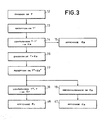
- This next step (51) consists in testing the link itself, in "half duplex” or “full duplex” mode according to what has been determined previously. An embodiment of this test is given in FIG. 3.
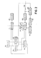
- FIG. 2 represents an embodiment of the device according to the invention.
- This device comprises at least two modems connected by a data transmission channel, constituted for example by a telephone line.
- a data transmission channel constituted for example by a telephone line.
- the modems namely its modulator-demodulator part (11), its associated electronic circuits (61 to 71) which ensure the implementation of the method described above, and the transmission line (120) are represented.
- the modem situated at the other end of the line is identical to that which is represented, in order to satisfy one of the basic principles of the present invention, namely the trivialization of modems.
- the method according to the invention begins with the triggering of the test by a command supplied to a sequencer 71, which has the function of the timed triggering of the three tests described above and the command accordingly of the various circuits of the device.
- the sequencer 71 is connected to a display device 67 which indicates which of the tests is in progress at all times.
- the modulator-demodulator circuit 11 of the modem is connected to a control element 61 for bringing the original modem into contact with another modem on the network.
- the next step in the process of Figure 1 is the test of the original modem. This takes place in two stages: first the test of the control channel (step 21), then the test of the modulation-demodulation function of the data channel (step 24). In one embodiment, these two tests can " take place in the same way, using a set of four circuits 62, 63, 64 and 65, and a signal generator 66: the sequencer 71 controls to the generator 66 the transmission of a determined message, preferably consisting of a series of bits of the same value, which is modulated by the circuit 11 and directed towards an attenuation line 63, which has the function of imposing on the signal the maximum attenuation compatible with the proper functioning of the modem.
- Circuit 65 is a circuit switch controlled by the sequencer 71, making it possible to connect the modem 11 to the attenuation line 63 during this test.
- This attenuated signal is then received by the demodulator part of the circuit 11 and sent to a comparator 68, controlled by the sequencer 71, which has the function of comparing the message demodulated by the circuit 11 with the message supplied by the generator 66, and kept in a memory element belonging for example to the comparator 68. If the latter finds a sufficient identity, it sends a message of correct operation to the sequencer 71, which allows to go to the next step of the test.
- a display device 70 which may or may not be separate from the device 67, as well as to the sequencer 71, in order to cause the process to stop.
- a scrambler-scrambler device 62 of pseudo-random type which has the function of scrambling the signal transmitted by the modem of a known manner, which corresponds to a self-synchronizing jammer-descrambler device 64.
- the insertion of interference into a transmission system makes it possible to use test messages that are simple to generate and recognize, without therefore being placed in transmission conditions that are too favorable.
- the test can consist simply in verifying that, when a finite series of bits of the same value are emitted, one effectively obtains after modulation and demodulation the presence of the two states, zero and one of the signal.
- the comparator 68 when the comparator 68 does not detects no error in this step, it transmits a signal to the sequencer 71 which allows it to pass to the next test, namely the test of the end modem.
- this step is broken down into testing the control channel itself and then testing the data channel; this stage proceeds in the same way, with one exception which concerns the information of the modem which is the source of a possible operational failure.
- the modem illustrated in FIG. 2 is the end modem. It therefore receives via the link 120 a test message ordering it to loop back on itself (step 30 of FIG. 1), then the test successively of the control channel and of the data channel.
- the test of the data channel is described below.
- the original modem then sends a test message preferably made up as above of a set of bits of the same value transmitted by the channel 120, possibly and for the same reasons as before, via two jammer-unscrambler devices such as 62.
- the modem 11 transmits the message to the comparator 68, which determines whether or not the received message is identical to the test message. As before, this operation is repeated a certain number of times, the iterations being for example counted by a counter 69, controlled by the sequencer 71. After a certain number of iterations showing correct operation, it is sent to the modem originates a message indicating that there is no error at the end modem.
- the total duration of the test is of the order of 10 4 bits
- the duration of the iteration in question here is 2000 bits
- the original modem must receive 5 messages of correct operation. The absence of one of these messages is reflected in the originating modem by a signal intended for the display device 70 and the sequencer 71 for stopping the process.
- the counter 69 of the original modem sends a message to the sequencer 71 of this same original modem, the sequencer ordering the next step, namely the unwinding of the end modem (step 41 in FIG. 1) then launching of the link test itself by the step, 50 (FIG. 1) of the choice of the connection mode described above, and finally the test of the connection itself (step 51 in FIG. 1), one embodiment of which is described in FIG. 3, in relation to figure 2.
- the first step of the method described in FIG. 3, carried out immediately after the choice of the transmission mode "half" or “full duplex", is illustrated by a block 12 in the figure. It consists of the transmission of a predefined message, called T, by the modem chosen as the origin of the test. Referring to FIG. 2, it can be seen that this transmission is carried out by the generator 66 on command from the sequencer 71, the form of the message T possibly being for example stored in a memory element belonging to the sequencer 71.
- the next step, marked 13 in the figure, consists in receiving the message T by the end modem; this received message is called T and, depending on whether the transmission was carried out with or without error, it is or is not identical to T.
- the next step, marked 14 in the figure, consists for the end modem in carrying out the comparison of the message T 'which it has received with the message T which has been sent, by means of the comparator 68 of FIG. 2.
- the modem in deduces the existence or non-existence of a transmission error in the direction from the origin modem to the end modem, that is to say a forward error. This information is called E a .
- this information E is displayed (step 15) on the display 70 of the end modem.
- the end modem sends a message to the originating modem containing the previous message T accompanied by a message representing the error E (step 16).
- the comparator output information is directed on the one hand to the sequencer 71 so that it supplies the signal T to the generator 66 and, on the other hand, to the generator 66 for the transmission of the message representing E.
- the information displayed is also directed to the sequencer 71 to indicate the end of the test.
- a forward transmission error results in the transmission by the modem end of M bits of value opposite to that of the signal T, namely M bits equal to zero in the example above; analogously to what is said above, when the comparator 68 of the original modem detects an error, the counter 69 counts the number b and if b is greater than M / 2, we deduce that it s is a go error.
Abstract
Description
La présente invention se rapporte au domaine des transmissions de données numériques et elle a plus particulièrement pour objet un procédé de test automatique d'un système de transmission de données, constitué par au moins deux modems et une ligne de transmission. L'invention a également pour objet un dispositif assurant la mise en oeuvre de ce procédé.The present invention relates to the field of digital data transmissions and it relates more particularly to a method for automatic testing of a data transmission system, consisting of at least two modems and a transmission line. The invention also relates to a device ensuring the implementation of this method.
Lorsque l'on désire traiter des informations à distance, il est connu de relier une unité centrale de traitement de données à un ou plusieurs organes périphériques de saisie et de visualisation de ces données, par une voie de transmission, par exemple une ligne téléphonique. Il est connu d'utiliser alors des dispositifs modulateurs démodulateurs de données numériques, ou modems, comme interface entre la voie de transmission de données et les unités de traitement de ces données, à chaque extrémité de la ligne.When it is desired to process information remotely, it is known to connect a central data processing unit to one or more peripheral organs for capturing and viewing this data, by a transmission channel, for example a telephone line. It is known to then use modulator devices for demodulating digital data, or modems, as the interface between the data transmission channel and the data processing units, at each end of the line.
En ce qui concerne la maintenance de tels équipements, le faible coût relatif des modems vis-à-vis des systèmes de traitement de données proprement dits pose un problème d'ordre économique au fabricant des modems. En effet, d'une part le non fonctionnement d'une liaison provoque l'immobilisation de matériels coûteux: l'utilisateur du système désire en conséquence un dépannage rapide ; d'autre part les interventions rapides pour la vérification des liaisons sont financièrement très lourdes pour le fabricant de modems vis-à-vis du prix du matériel fabriqué. Elles doivent donc, en conséquence, être réduites autant que possible.With regard to the maintenance of such equipment, the low relative cost of the modems vis-à-vis the data processing systems themselves poses an economic problem for the manufacturer of the modems. In fact, on the one hand, the non-functioning of a link provokes the immobilization of expensive equipment: the user of the system therefore desires rapid troubleshooting; on the other hand, rapid interventions for the verification of links are financially very heavy for the modem manufacturer vis-à-vis the price of the material manufactured. They should therefore be reduced as much as possible.
Différents systèmes de test sont connus à ce jour, parmi lesquels on peut citer le générateur et compteur d'erreurs, qui est un dispositif distinct du modem, que l'on connecte à celui-ci et qui permet de faire transiter sur les liaisons une séquence déterminée de signaux ; cette séquence est soit analysée à l'autre extrémité de la ligne par un second dispositif générateur et compteur d'erreurs, soit renvoyé sur la même ligne par le modem situé à l'autre extrémité de cette ligne, rebouclé sur lui-même. Cette solution présente différents inconvénients, notamment le coût du matériel de test, le manque de précision du diagnostic d'erreur lorsque n'est utilisé qu'un seul dispositif de test, et la nécessité d'avoir des opérateurs qualifiés et deux dispositifs de test, un à chaque extrémité de la liaison, lorsque la source d'erreurs doit être localisée plus précisément, c'est-à-dire lorsque l'on désire savoir si les erreurs proviennent du modem central, du modem périphérique ou encore de la ligne de transmission elle-même.Various test systems are known to date, among which there may be mentioned the generator and error counter, which is a device distinct from the modem, which is connected to the latter and which makes it possible to pass over the links a specific sequence of signals; this sequence is either analyzed at the other end of the line by a second generator and error counter device, is returned on the same line by the modem located at the other end of this line, looped back on itself. This solution has various drawbacks, notably the cost of the test equipment, the lack of precision of the error diagnosis when only one test device is used, and the need to have qualified operators and two test devices. , one at each end of the link, when the source of errors must be located more precisely, that is to say when one wishes to know whether the errors come from the central modem, the peripheral modem or even the line of transmission itself.
La présente invention a pour objet un procédé réalisant automatiquement, à partir de l'une des extrémités d'une liaison et par une commande unique, le test successivement du modem situé à cette extrémité, du modem situé à l'autre extrémité, et enfin de la ligne elle-même, et cela quel que soit le mode de fonctionnement de la liaison, sans intervention d'opérateur à l'autre extrémité. En outre, le déroulement du test est interrompu lorsqu'un défaut de fonctionnement est détecté, fournissant ainsi un diagnostic précis sur la localisation de ces défauts. Enfin, les différents ordres et informations nécessaires aux tests ou fournis par eux sont transmis d'un modem à l'autre sur un canal distinct de celui utilisé pour la transmission des données, le canal, la vitesse de transmission et la forme des informations étant choisis de façon telle que celles-ci restent utilisables en cas de mauvais fonctionnement des différents composants du système, permettant ainsi la réalisation des tests dans les conditions où ils sont les plus nécessaires.The subject of the present invention is a method performing automatically, from one of the ends of a link and by a single command, the successive test of the modem located at this end, of the modem located at the other end, and finally of the line itself, regardless of the operating mode of the link, without operator intervention at the other end. In addition, the test run is interrupted when a malfunction is detected, thus providing a precise diagnosis on the location of these faults. Finally, the different orders and information necessary for the tests or supplied by them are transmitted from one modem to another on a channel separate from that used for the transmission of the data, the channel, the speed of transmission and the form of the information being chosen in such a way that they remain usable in the event of malfunction of the various components of the system, thus enabling tests to be carried out under the conditions where they are most needed.
Plus précisément, le procédé de test selon l'invention comporte principalement les étapes suivantes :
- - le test de la fonction modulation-démodulation d'un premier modem, choisi comme origine du test, pendant une durée prédéfinie ;
- - en cas de défauts de fonctionnement du modem origine, l'affichage d'une information indiquant la défaillance de ce modem et l'arrêt du déroulement du procédé ;
- - en l'absence de défauts de fonctionnement pendant toute cette durée, le test de la fonction modulation-démodulation du modem situé à l'autre extrémité de la ligne de transmission, appelé modem extrémité, pendant une durée prédéfinie ;
- - en cas de défauts de fonctionnement du modem extrémité, l'affichage sur le modem origine d'une information indiquant la défaillance et provoquant l'arrêt du procédé ;
- - en l'absence de défauts de fonctionnement pendant toute la durée requise, le test de la ligne de transmission elle-même, dans les deux sens, également pendant une durée prédéfinie, et l'affichage sur le modem origine des éventuelles erreurs de transmission.
- - the test of the modulation-demodulation function of a first modem, chosen as the origin of the test, for a predefined period;
- - in the event of malfunctions of the original modem, the display of information indicating the failure of this modem and the termination of the process;
- - in the absence of malfunctions during this entire period, testing the modulation-demodulation function of the modem located at the other end of the transmission line, called the modem end, for a predefined period;
- - in the event of malfunctions of the end modem, the display on the origin modem of information indicating the failure and causing the process to stop;
- - in the absence of malfunctions for the entire required time, testing the transmission line itself, in both directions, also for a predefined period, and displaying on the modem the origin of any transmission errors .
L'invention a également pour objet un dispositif, intégrés aux modems, mettant en oeuvre ce procédé.The invention also relates to a device, integrated into modems, implementing this method.
D'autres objets, caractéristiques et résultats de l'invention ressortiront de la description suivante, donnée à titre d'exemple non limitatif et illustrée par les dessins annexés, qui représentent :
- - la figure 1, le schéma du procédé de test selon l'invention ;
- - la figure 2, le schéma d'un mode de réalisation du dispositif selon l'invention ;
- - la figure 3, le détail de l'une des étapes du procédé illustré sur la figure 1.
- - Figure 1, the diagram of the test method according to the invention;
- - Figure 2, the diagram of an embodiment of the device according to the invention;
- - Figure 3, the detail of one of the steps of the method illustrated in Figure 1.
Sur ces différentes figures, les mêmes références se rapportent aux mêmes éléments.In these different figures, the same references relate to the same elements.
Le procédé décrit figure 1 commence par une étape, référencée 1, de déclenchement d'un test entre deux modems, l'un de ces modems étant par exemple relié à une unité centrale de traitement de données et l'autre modem étant relié à un des organes périphériques d'un système qui peut en comporter plusieurs. L'un quelconque des modems est choisi comme modem origine, à partir duquel est commandé le test et où viennent s'afficher les résultats, l'autre modem concerné par le test étant appelé modem extrémité ; les autres modems que peut comporter le système sont prévenus du test en cours lors de cette étape.The method described in FIG. 1 begins with a step, referenced 1, of triggering a test between two modems, one of these modems being for example connected to a central data processing unit and the other modem being connected to a peripheral organs of a system which may include several. Any of the modems is chosen as the origin modem, from which the test is ordered and where the results are displayed, the other modem concerned by the test being called the end modem; other modems that the system may include are notified of the test in progress during this step.
Le déclenchement du test s'effectue par l'émission par le modem origine d'un ordre de forme déterminée vers tous les autres modems du système ; le test n'est déclenché qu'après réception par le modem origine d'un accusé de réception positif, ou acquittement, émis par le modem extrémité. Les ordres mentionnés ci-dessus peuvent par exemple prendre la forme d'une série de bits constituée de trois parties : la première, sur t bits, forme un message indiquant qu'il s'agit d'un ordre et peut être par exemple une suite de t bits identiques ; la seconde partie est constituée par l'adresse du modem extrémité concerné, sur u bits, et enfin la troisième partie sur v bits, caractérise l'ordre concerné. L'ordre est de préférence précédé par un drapeau constitué par exemple par une série de bits égaux à 1, émis pendant une durée de l'ordre d'une seconde. L'acquittement a de préférence la même forme que l'ordre lui-même.The test is triggered by the transmission by the modem origin of a specific form order to all the other modems in the system; the test is only triggered after receipt by the originating modem of a positive acknowledgment, or acknowledgment, sent by the end modem. The orders mentioned above can for example take the form of a series of bits made up of three parts: the first, on t bits, forms a message indicating that it is about an order and can be for example a sequence of t identical bits; the second part consists of the address of the end modem concerned, on u bits, and finally the third part on v bits, characterizes the order concerned. The order is preferably preceded by a flag constituted for example by a series of bits equal to 1, transmitted for a duration of the order of one second. The acquittal preferably has the same form as the order itself.
Par ailleurs, ces ordres de test sont émis sur un canal différent de celui qui est emprunté par les données elles-mêmes ce canal se situe de préférence en bas de la bande passante des modems et les échanges d'informations s'y effectuent à très basse vitesse, de l'ordre de la dizaine de Bauds, afin que lès informations de test soient perturbées au minimum par une mauvaise qualité de la liaison.Furthermore, these test orders are issued on a channel different from that which is used by the data themselves. This channel is preferably located at the bottom of the bandwidth of the modems and the information exchanges take place there at very low speed, of the order of ten Bauds, so that the test information is disturbed as a minimum by poor quality of the link.
Les étapes suivantes du procédé selon l'invention (références 20 à 27 sur la figure) concernent le modem origine.The following steps of the method according to the invention (
L'étape 20 consiste en la déconnexion du modem origine de la ligne de transmission et le bouclage de ce modem sur lui-même, de façon à permettre le test de son fonctionnement propre.
L'étape suivante (21) est rendue nécessaire lorsque, comme mentionné plus haut, les procédures de test se déroulent sur un canal séparé du canal de données : elle consiste à tester le fonctionnement de la voie de commande du modem origine. Ce test s'effectue à l'aide d'un ensemble de circuits décrits figure 2. Si le fonctionnement de cette voie de commande n'est pas correct, l'information correspondante est affichée (étape 23) et provoque l'arrêt du déroulement du test. Au contraire, dans le cas où la voie de commande fonctionne correctement, un dispositif de temporisation détermine si le test doit être repris ou non (étape 22) ; cette temporisation peut se faire par exemple par comptage du nombre de bits émis pour tester la voie de commande ; à titre d'exemple, le fonctionnement de la voie de commande peut être considéré comme correct si aucune erreur n'est détectée sur 10 000 bits de test, ce qui correspond, pour une fréquence de 2 400 Hz, à une durée d'environ 4 s.The next step (21) is made necessary when, as mentioned above, the test procedures take place on a channel separate from the data channel: it consists in testing the operation of the control channel of the original modem. This test is carried out using a set of circuits described in Figure 2. If the operation of this control channel is not correct, the corresponding information is displayed (step 23) and causes the flow to stop. of the test. On the contrary, in the case where the control channel functions correctly, a time delay device determines whether or not the test should be repeated (step 22); this time delay can be done for example by counting the number of bits transmitted to test the control channel; for example, the operation of the control channel can be considered correct if no error is detected on 10 000 test bits, which corresponds, for a frequency of 2400 Hz, to a duration of approximately 4 sec.
A l'issue de ce test 22, qui détermine donc si la durée choisie pour le test 21 est atteinte (ou si le nombre de bits de test est atteint), c'est la fonction modulateur-démodulateur du modem origine, sur le canal emprunté par les données, qui est testée (étape 24). Pour ce test, de la même manière, lorsqu'un défaut de fonctionnement est détecté, l'information correspondante est affichée (étape 26) et provoque l'arrêt du déroulement du test. Lorsque au contraire aucune erreur n'est détectée, le test est repris autant de fois que nécessaire pour avoir une bonne probabilité de fonctionnement correct. Comme précédemment, lorsque le nombre d'itérations prédéfini est atteint (test 25), on passe à l'étape suivante (27), qui est la reconnexion du modem origine à la ligne de transmission, marquant la fin du test de celui-ci.At the end of this
Les étapes suivantes (30 à 41) conernent le test en boucle fermé du modem extrémité. Ce test commence par la mise (étape 30) en boucle de ce modem, c'est-à-dire sa déconnexion de la ligne, avec reconnexion commandée par lui-même, en fin de test.The following steps (30 to 41) relate to the end-loop closed loop test. This test begins with the looping (step 30) of this modem, that is to say its disconnection from the line, with reconnection controlled by itself, at the end of the test.
De façon analogue à l'étape 21 précédente pour le modem origine est alors effectué le test de la voie de commande du modem extrémité (étape 31). Contrairement à ce qui a été dit précédemment, la détection d'une erreur indique ici que soit la voie de commande, soit la ligne de transmission est défectueuse. Cette défectuosité est affichée (étape 35) sur le modem extrémité en cours de test. Dans le cas où n'est détectée aucune erreur, le test est repris comme précédemment après le passage par une étape de temporisation (ou de comptage) 32. Lorsque le nombre de bits désiré est atteint, le modem extrémité se reconnecte à la ligne et émet (étape 33) un message de bon fonctionnement à l'intention du modem origine. Si le modem origine ne reçoit pas un tel message, il affiche une information indiquant un mauvais fonctionnement qui se situe donc soit au niveau du modem extrémité, soit au niveau de la ligne. Comme précédemment, cette erreur arrête le déroulement du procédé.Similarly to the
Afin de donner plus de redondance à l'information de test, il est préférable d'insérer une seconde étape de temporisation (34) permettant de reprendre un certain nombre de fois le processus 31, 32, 33 qui vient d'être décrit. A titre d'exemple, si l'on choisit la même valeur pour l'étape de comptage 34 que pour les étapes 22 ou 25, à savoir 10 000 bits, la temporisation de l'étape 32 peut alors correspondre au comptage de 2 000 bits, ce qui conduit à l'émission de cinq messages de bon fonctionnement.In order to give more redundancy to the test information, it is preferable to insert a second time-out step (34) making it possible to repeat the
Après le test de la voie de commande du modem extrémité se déroule le test (étape 36) de la fonction de modulation-démodulation sur le canal des données, de façon analogue à l'étape 24. La détection d'un mauvais fonctionnement provoque l'affichage (étape 40) de l'information correspondante et arrête le déroulement du test. Au contraire, le bon fonctionnement du modem après des étapes de temporisation (37 et 39) et d'information du modem origine (38), analogues aux étapes 32, 34 et 33 respectivement décrites ci-dessus, conduit au débouclage du modem extrémité (étape 41) et à la fin du test de celui-ci.After the test of the end modem control channel, the test (step 36) of the modulation-demodulation function on the data channel takes place, similar to step 24. The detection of a malfunction causes the display (step 40) of the corresponding information and stops the running of the test. On the contrary, the correct functioning of the modem after time-out (37 and 39) and information from the original modem (38) steps, similar to
Il est ensuite procédé au test de la liaison elle-même, qui commence, dans un mode de réalisation préféré, par une étape 50 correspondant au choix du mode de transmission dans lequel se déroulera le test, à savoir transmission en "full duplex" ou "half duplex". On rappelle que l'on entend par "half duplex", ou alternat ou semi duplex, un mode de fonctionnement dans lequel les modems utilisent leur ligne de transmission l'un après l'autre, et par "full duplex", ou duplex intégral, un fonctionnement dans lequel les modems peuvent utiliser la ligne en même temps, ceci étant rendu possible soit par l'attribution aux informations de bandes de fréquence différentes selon leur sens de parcours, soit par un dédoublement des liaisons électriques.The link itself is then tested, which begins, in a preferred embodiment, with a step 50 corresponding to the choice of the transmission mode in which the test will take place, namely "full duplex" transmission or "half duplex". Remember that "half duplex" or alternat or half duplex means an operating mode in which the modems use their transmission line one after the other, and by "full duplex", or full duplex , an operation in which the modems can use the line at the same time, this being made possible either by the allocation to the information of bands of fre quence different according to their direction of travel, or by a splitting of the electrical connections.
Dans cette étape 50, comme dans le reste du procédé, le même principe est retenu, à savoir la commande de tous les tests par le modem choisi comme origine ; comme, par ailleurs, surtout dans le cas d'un réseau multipoints, les deux modems concernés peuvent ne pas se trouver dans le même état de fonctionnement, il est fréquent que le modem relié à l'unité centrale fonctionne en "full duplex" alors qu'un certain nombre des modems reliés aux unités périphériques fonctionnent en "half duplex". ; dans ce dernier cas, la procédure de test doit se dérouler en "half duplex".In this step 50, as in the rest of the method, the same principle is retained, namely the command of all the tests by the modem chosen as the origin; as, moreover, especially in the case of a multipoint network, the two modems concerned may not be in the same operating state, it is frequent that the modem connected to the central unit operates in "full duplex" then that a certain number of modems connected to peripheral units operate in "half duplex". ; in the latter case, the test procedure must take place in "half duplex".
Cette étape (50) de choix peut s'effectuer par exemple de la façon suivante : - le modem origine teste tout d'abord son mode de fonctionnement "half duplex" ou "full duplex" et émet un ordre de test dans le mode de fonctionnement correspondant ;
- - le modem extrémité qui reçoit cet ordre teste à son tour son état ;
- - si le modem extrémité est également en "full duplex", il émet un acquittement pour un test en "full duplex", qui est, conformément à ce qui est dit plus haut, de la même forme que l'ordre reçu ; à la réception de l'acquittement par le modem origine, l'étape suivante est enchaînée ;
- - lorsque le modem extrémité est en état "half duplex", il émet alors un acquittement pour un test en "half duplex", c'est-à-dire que la troisième partie de l'ordre mentionné plus haut indique que le test demandé doit se dérouler en "half duplex". De la même manière, à la réception de l'acquittement est enchaînée l'étape suivante.
- - the end modem which receives this order in turn tests its state;
- - if the end modem is also in "full duplex", it sends an acknowledgment for a test in "full duplex", which is, in accordance with what is said above, of the same form as the order received; upon receipt of the acknowledgment by the originating modem, the next step is chained;
- - when the end modem is in "half duplex" state, it then sends an acknowledgment for a "half duplex" test, that is to say that the third part of the order mentioned above indicates that the test requested must take place in "half duplex". In the same way, upon receipt of the acknowledgment, the next step is chained.
Cette étape suivante (51) consiste à tester la liaison elle-même, en mode "half duplex" ou "full duplex" selon ce qui a été déterminé précédemment. Un mode de réalisation de ce test est donné figure 3.This next step (51) consists in testing the link itself, in "half duplex" or "full duplex" mode according to what has been determined previously. An embodiment of this test is given in FIG. 3.
Dans le cas où une erreur est détectée, elle est affichée dans une étape 53 au niveau du modem origine. Dans le cas où aucune erreur n'est détectée, le test de la liaison est repris autant de fois qu'autorisé par une étape 52 de temporisation.In the event that an error is detected, it is displayed in a step 53 at the level of the original modem. In the event that no error is detected, the link test is repeated as many times as authorized by a
La figure 2 représente un mode de réalisation du dispositif selon l'invention.FIG. 2 represents an embodiment of the device according to the invention.
Ce dispositif comporte au moins deux modems reliés par une voie de transmission de données, constituée par exemple par une ligne téléphonique. Sur la figure, seuls l'un des modems, à savoir sa partie modulateur-démodulateur (11), ses circuits électroniques associés (61 à 71) qui assurent la réalisation du procédé décrit précédemment, et la ligne de transmission (120) sont représentés, étant entendu que le modem situé à l'autre extrémité de la ligne est identique à celui qui est représenté, afin de satisfaire à l'un des principes de base de la présente invention, à savoir la banalisation des modems.This device comprises at least two modems connected by a data transmission channel, constituted for example by a telephone line. In the figure, only one of the modems, namely its modulator-demodulator part (11), its associated electronic circuits (61 to 71) which ensure the implementation of the method described above, and the transmission line (120) are represented. , it being understood that the modem situated at the other end of the line is identical to that which is represented, in order to satisfy one of the basic principles of the present invention, namely the trivialization of modems.
Le procédé selon l'invention commence par le déclenchement du test par une commande fournie à un séquenceur 71, qui a pour fonction le déclenchement temporisé des trois tests décrits précédemment et la commande en conséquence des divers circuits du dispositif. Le séquenceur 71 est relié à un dispositif d'affichage 67 qui indique celui des tests qui est en cours à chaque instant.The method according to the invention begins with the triggering of the test by a command supplied to a
Pour la réalisation de l'étape 1 de la figure 1, le circuit modulateur-démodulateur 11 du modem est relié à un élément de commande 61 de mise en relation du modem origine avec un autre modem du réseau.To carry out
L'étape suivante du procédé de la figure 1 est le test du modem origine. Celui-ci se déroule en deux étapes : tout d'abord le test de la voie de commande (étape 21), puis le test de la fonction modulation-démodulation de la voie de données (étape 24). Dans un mode de réalisation, ces deux tests peuvent"se dérouler de la même manière, à l'aide d'un ensemble de quatre circuits 62, 63, 64 et 65, et d'un générateur de signaux 66: le séquenceur 71 commande au générateur 66 l'émission d'un message déterminé, constitué de préférence d'une suite de bits de même valeur, qui est modulé par le circuit 11 et dirigé vers une ligne d'atténuation 63, qui a pour fonction d'imposer au signal le maximum d'atténuation compatible avec le bon fonctionnement du modem. Le circuit 65 est un circuit d'aiguillage commandé par le séquenceur 71, permettant de relier lors de ce test le modem 11 à la ligne d'atténuation 63. Ce signal atténué est ensuite reçu par la partie démodulateur du circuit 11 et envoyé à un comparateur 68, commandé par le séquenceur 71, qui a pour fonction de comparer le message démodulé par le circuit 11 avec le message fourni par le générateur 66, et conservé dans un élément de mémoire appartenant par exemple au comparateur 68. Si celui-ci constate une identité suffisante, il envoie un message de bon fonctionnement au séquenceur 71, ce qui permet de passer à l'étape suivante du test. Au contraire, si le comparateur 68 décèle une différence entre message et message reçu, une information d'erreur est envoyée à un dispositif d'affichage 70, qui peut être distinct ou non du dispositif 67, ainsi qu'au séquenceur 71, afin de provoquer l'arrêt du procédé.The next step in the process of Figure 1 is the test of the original modem. This takes place in two stages: first the test of the control channel (step 21), then the test of the modulation-demodulation function of the data channel (step 24). In one embodiment, these two tests can " take place in the same way, using a set of four
Par ailleurs, dans un mode de réalisation préféré, on interpose entre le modem 11 et la ligne d'atténuation 63 un dispositif brouilleur-débrouilleur 62 de type pseudo-aléatoire, qui a pour fonction de brouiller le signal émis par le modem d'une façon connue, auquel correspond un dispositif brouilleur-débrouilleur 64 autosynchronisable. En effet, ainsi qu'il est connu,l'insertion d'un brouillage dans un système de transmission permet d'utiliser des messages de test simples à engendrer et à reconnaître, sans se trouver placé de ce fait dans des conditions de transmission trop favorables.Furthermore, in a preferred embodiment, there is interposed between the
Par ailleurs, dans une variante de réalisation, il est possible de procéder pour la voie de commande à un test simplifié. En effet, lorsque la voie de commande est séparée de la voie empruntée par les données, il a été indiqué ci-dessus qu'il est préférable d'utiliser le bas de la bande passante des modems à une vitesse très faible, de l'ordre de la dizaine de Bauds ; dans ce cas, le test peut consister simplement à vérifier que, lorsqu'on émet une série finie de bits de même valeur, on obtient effectivement après modulation et démodulation la présence des deux états, zéro et un du signal.Furthermore, in an alternative embodiment, it is possible to carry out a simplified test for the control channel. Indeed, when the control channel is separated from the channel taken by the data, it has been indicated above that it is preferable to use the low bandwidth of the modems at a very low speed, from the order of ten Bauds; in this case, the test can consist simply in verifying that, when a finite series of bits of the same value are emitted, one effectively obtains after modulation and demodulation the presence of the two states, zero and one of the signal.
Ainsi qu'il est dit ci-dessus, lorsque le comparateur 68 ne détecte aucune erreur dans cette étape, il transmet un signal au séquenceur 71 qui lui permet de passer au test suivant, à savoir le test du modem extrémité.As stated above, when the
Comme pour le modem origine, cette étape se décompose en test de la voie de commande elle-même puis en test de la voie des données ; cette étape se déroule de la même manière, à une exception près qui concerne l'information du modem origine d'une éventuelle défaillance de fonctionnement.As with the original modem, this step is broken down into testing the control channel itself and then testing the data channel; this stage proceeds in the same way, with one exception which concerns the information of the modem which is the source of a possible operational failure.
On suppose dans ce cas, pour la clarté de l'exposé, que le modem illustré figure 2 est le modem extrémité. Il reçoit donc par l'intermédiaire de la liaison 120 un message de test lui ordonnant une mise en boucle sur lui-même (étape 30 de la figure 1), puis le test successivement de la voie de commande et de la voie de données. A titre d'exemple, on décrit ci-après le test de la voie de données.It is assumed in this case, for the sake of clarity, that the modem illustrated in FIG. 2 is the end modem. It therefore receives via the link 120 a test message ordering it to loop back on itself (step 30 of FIG. 1), then the test successively of the control channel and of the data channel. By way of example, the test of the data channel is described below.
Le modem origine émet alors un message de test constitué de préférence comme précédemment d'un ensemble de bits de même valeur transmis par la voie 120, éventuellement et pour les mêmes raisons que précédemment, par l'intermédiaire de deux dispositifs brouilleur-débrouilleurs tels que 62. Après démodulation, le modem 11 transmet le message au comparateur 68, qui détermine si le message reçu est identique ou non au message de test. Comme précédemment, cette opération est réitérée un certain nombre de fois, les itérations étant par exemple comptées par un compteur 69, commandé par le séquenceur 71. Au bout d'un certain nombre d'itérations montrant un fonctionnement correct, il est envoyé au modem origine un message indiquant l'absence d'erreur au niveau du modem extrémité. Dans l'exemple décrit précédemment, la durée totale du test est de l'ordre de 104 bits, la durée de l'itération dont il est question ici est de 2 000 bits et le modem origine doit recevoir 5 messages de fonctionnement correct. L'absence de l'un de ces messages se traduit au niveau du modem origine par un signal à destination du dispositif d'affichage 70 et du séquenceur 71 pour arrêt du procédé. Lorsque le test s'est entièrement déroulé de façon satisfaisante, le compteur 69 du modem origine envoie un message au séquenceur 71 de ce même modem origine, le séquenceur ordonnant l'étape suivante, à savoir le débouclage du modem extrémité (étape 41 sur la figure 1) puis lancement du test de la liaison elle-même par l'étape, 50 (figure 1) du choix du mode de liaison décrit ci-dessus, et enfin le test de la liaison elle-même (étape 51 figure 1) dont un mode de réalisation est décrit figure 3, en relation avec la figure 2.The original modem then sends a test message preferably made up as above of a set of bits of the same value transmitted by the
La première étape du procédé décrit figure 3, effectuée immédiatement après le choix du mode de transmission "half" ou "full duplex", est illustrée par un bloc 12 sur la figure. Elle consiste en l'émission d'un message prédéfini, appelé T, par le modem choisi comme origine du test. En se reportant à la figure 2, on voit que cette émission est réalisée par le générateur 66 sur commande du séquenceur 71, la forme du message T pouvant être par exemple mémorisée dans un élément de mémoire appartenant au séquenceur 71.The first step of the method described in FIG. 3, carried out immediately after the choice of the transmission mode "half" or "full duplex", is illustrated by a
L'étape suivante, repérée 13 sur la figure, consiste en la réception du message T par le modem extrémité ; ce message reçu est appelé T et, suivant que la transmission s'est effectuée sans ou avec erreur, il est ou n'est pas identique à T.The next step, marked 13 in the figure, consists in receiving the message T by the end modem; this received message is called T and, depending on whether the transmission was carried out with or without error, it is or is not identical to T.
L'étape suivante, repérée 14 sur la figure, consiste pour le modem extrémité à effectuer la comparaison du message T' qu'il a reçu avec le message T qui a été émis, grâce au comparateur 68 de la figure 2. Le modem en déduit l'existence ou la non existence d'une erreur de transmission dans le sens modem origine vers modem extrémité, c'est-à-dire une erreur aller. Cette information est appelée Ea.The next step, marked 14 in the figure, consists for the end modem in carrying out the comparison of the message T 'which it has received with the message T which has been sent, by means of the
Dans un mode de réalisation, cette information E est affichée (étape 15) sur l'afficheur 70 du modem extrémité.In one embodiment, this information E is displayed (step 15) on the display 70 of the end modem.
Parallèlement à cet affichage, le modem extrémité émet vers le modem origine un message comportant le message T précédent accompagné d'un message représentant l'erreur E (étape 16). Dans le dispositif de la figure 2, l'information de sortie du comparateur est dirigée d'une part vers le séquenceur 71 afin qu'il fournisse le signal T au générateur 66 et, d'autre part, vers le générateur 66 pour l'émission du message représentant E .In addition to this display, the end modem sends a message to the originating modem containing the previous message T accompanied by a message representing the error E (step 16). In the device of Figure 2, the comparator output information is directed on the one hand to the
L'étape suivante, repérée 17, est la réception par le modem origine du message émis dans l'étape précédente, le message reçu étant référencé T"+E". Ce message est traité de deux façons :
- - d'une part (
étape 18 sur la figure), le modem origine effectue la comparaison (comparateur 68 de la figure 2) du message T" reçu avec le message T et il en déduit, comme précédemment le modem extrémité (étape 14), l'existence ou la non-existence d'erreurs de transmission dans le sens modem extrémité vers modem origine. Cette information, appelée erreur retour, est notée E . Elle est affichée (afficheur 70 de la figure 2) sur le modem origine : c'est l'étape repérée 46 ; - - d'autre part (étape 19), le modem origine effectue une interprétation du message E"a reçu, parce que ce dernier est susceptible d'être entaché d'erreurs, afin de reconstituer le message E initial ; celui-ci est afors affiché (étape 47) sur le modem origine. L'étape 19 est réalisée par exemple sur commande du séquenceur 71 par comptage des bits ayant une certaine valeur,
par le compteur 69. C'est alors l'information de sortie du compteur qui est dirigée vers l'afficheur 70 pourréaliser l'étape 47.
- - on the one hand (
step 18 in the figure), the originating modem compares (comparator 68 in figure 2) the message T "received with the message T and deduces therefrom, as previously the end modem (step 14) , the existence or non-existence of transmission errors in the direction modem end to origin modem. This information, called return error, is noted E. It is displayed (display 70 of FIG. 2) on the origin modem: this is the step marked 46; - - the other part (step 19), the originating modem performs interpretation of the message E "received, because the latter is likely to be flawed, in order to reconstitute the original E message; it is AFORS displayed (step 47) on the original modem Step 19 is carried out for example on command of the
sequencer 71 by counting the bits having a certain value, by thecounter 69. It is then the output information of the counter which is directed to the display 70 to carry outstep 47.
Dans l'un ou l'autre cas, l'information affichée est également dirigée vers le séquenceur 71 pour lui indiquer la fin du test.In either case, the information displayed is also directed to the
A titre d'exemple, les signaux utilisés pour ce test peuvent être les suivants :
- - pour le message T, une suite de bits de même valeur,
par exemple 1 ; dans le cas d'un test en "half duplex", il s'agit d'un nombre N limité de bits, par exemple N = 50 : dans le cas d'un test "full duplex", il s'agit d'une suite de bits ininterrompue pendant toute la durée du test ; - - pour le message Ea, dans le cas d'un test en "half duplex", il s'agit de préférence d'une suite de n bits émise par le modem extrémité, suivant immédiatement le message T, de même valeur que celui-ci lorsqu'il n'y a pas d'erreur de transmission dans le sens aller, et la valeur opposée dans le cas contraire. Lorsque le comparateur 68 (figure 2) du modem origine détecte une erreur, c'est-à-dire dans l'exemple choisi un bit égal à zéro, le compteur 69 en compte le nombre a et si a est supérieur à n/2, on en déduit qu'il s'agit d'une erreur aller.
- - for the message T, a series of bits of the same value, for example 1; in the case of a "half duplex" test, it is a limited number N of bits, for example N = 50: in the case of a "full duplex" test, it is an unbroken string of bits for the duration of the test;
- - for message E a , in the case of a "half duplex" test, it is preferably a series of n bits sent by the end modem, immediately following the message T, of the same value as that -this when there is no transmission error in the forward direction, and the opposite value otherwise. When the comparator 68 (FIG. 2) of the original modem detects an error, that is to say in the example chosen a bit equal to zero, the
counter 69 counts the number a and if a is greater than n / 2 , we deduce that this is a go error.
Dans le cas d'un test en "full duplex", une erreur de transmission dans le sens aller se traduit par l'émission par le modem extrémité de M bits de valeur opposée à celle du signal T, à savoir M bits égaux à zéro dans l'exemple ci-dessus ; d'une façon analogue à ce qui est dit ci-dessus, lorsque le comparateur 68 du modem origine détecte une erreur, le compteur 69 en compte le nombre b et si b est supérieur à M/2, on en déduit qu'il s'agit d'une erreur aller.In the case of a "full duplex" test, a forward transmission error results in the transmission by the modem end of M bits of value opposite to that of the signal T, namely M bits equal to zero in the example above; analogously to what is said above, when the
Il apparaît ainsi que la source des erreurs peut être détectée même en cas de liaison très fortement dégradée, du fait du très fort taux d'erreur admissible (50 %).It thus appears that the source of the errors can be detected even in the case of a very severely degraded link, due to the very high admissible error rate (50%).
Il a été ainsi décrit un test automatique d'un système constitué par une ligne de transmission reliée à au moins deux modems, permettant de vérifier successivement le bon fonctionnement de chacun des modems puis de la ligne elle-même, fournissant une localisation précise d'un éventuel défaut de fonctionnement même en cas de liaison fortement perturbée, et cela à partir de l'un quelconque des modems, qu'il s'agisse d'une liaison point à point, c'est-à-dire ne comportant qu'une unité centrale et une unité périphérique, ou une branche particulière d'une liaison multipoint. Par ailleurs, ce test met en oeuvre, autour du modulateur-démodulateur lui-même, un ensemble de circuits aisément intégrables à ce dernier.There has thus been described an automatic test of a system constituted by a transmission line connected to at least two modems, making it possible to successively check the correct operation of each of the modems and then of the line itself, providing a precise location of a possible malfunction even in the event of a highly disturbed link, and this from any of the modems, whether it is a point to point link, that is to say comprising only a central unit and a peripheral unit, or a particular branch of a multipoint link. Furthermore, this test implements, around the modulator-demodulator itself, a set of circuits that can easily be integrated into the latter.
Claims (8)
Applications Claiming Priority (2)
| Application Number | Priority Date | Filing Date | Title |
|---|---|---|---|
| FR7923246 | 1979-09-18 | ||
| FR7923246A FR2466143A1 (en) | 1979-09-18 | 1979-09-18 | METHOD AND DEVICE FOR AUTOMATICALLY TESTING A SYSTEM FOR TRANSMITTING DIGITAL DATA |
Publications (1)
| Publication Number | Publication Date |
|---|---|
| EP0025767A1 true EP0025767A1 (en) | 1981-03-25 |
Family
ID=9229756
Family Applications (1)
| Application Number | Title | Priority Date | Filing Date |
|---|---|---|---|
| EP80401318A Withdrawn EP0025767A1 (en) | 1979-09-18 | 1980-09-16 | Method and apparatus for automatically testing a digital data transmission system |
Country Status (2)
| Country | Link |
|---|---|
| EP (1) | EP0025767A1 (en) |
| FR (1) | FR2466143A1 (en) |
Cited By (10)
| Publication number | Priority date | Publication date | Assignee | Title |
|---|---|---|---|---|
| EP0380730A1 (en) * | 1989-02-02 | 1990-08-08 | Siemens Aktiengesellschaft | Method and circuit for checking the operational capability of a data transmission path |
| WO2001056200A1 (en) * | 2000-01-26 | 2001-08-02 | Vyyo, Ltd. | A unidirectional communication scheme for remote maintenance and co ntrol in a broadband wireless access system |
| US6498821B2 (en) | 2000-01-26 | 2002-12-24 | Vyyo, Ltd. | Space diversity method and system for broadband wireless access |
| US6856786B2 (en) | 2000-01-26 | 2005-02-15 | Vyyo Ltd. | Quality of service scheduling scheme for a broadband wireless access system |
| US6941119B2 (en) | 2000-01-26 | 2005-09-06 | Vyyo Ltd. | Redundancy scheme for the radio frequency front end of a broadband wireless hub |
| US6987754B2 (en) | 2000-03-07 | 2006-01-17 | Menashe Shahar | Adaptive downstream modulation scheme for broadband wireless access systems |
| US7123650B2 (en) | 2000-01-26 | 2006-10-17 | Vyyo, Inc. | Offset carrier frequency correction in a two-way broadband wireless access system |
| US7149188B2 (en) | 2000-01-26 | 2006-12-12 | Vyyo, Inc. | Distributed processing for optimal QOS in a broadband access system |
| US7298715B2 (en) | 2000-03-14 | 2007-11-20 | Vyyo Ltd | Communication receiver with signal processing for beam forming and antenna diversity |
| US7359434B2 (en) | 2000-01-26 | 2008-04-15 | Vyyo Ltd. | Programmable PHY for broadband wireless access systems |
Citations (5)
| Publication number | Priority date | Publication date | Assignee | Title |
|---|---|---|---|---|
| US3786187A (en) * | 1971-03-23 | 1974-01-15 | Alitalia Spa | Apparatus for testing systems and data transmitting networks by simulation |
| FR2317829A1 (en) * | 1975-07-09 | 1977-02-04 | Siemens Ag | AUTOMATIC VERIFICATION PROCESS OF THE OPERATING CAPACITY OF THE DATA TRANSMISSION SYSTEM |
| US4039751A (en) * | 1972-04-24 | 1977-08-02 | General Datacomm Industries, Inc. | Method and apparatus for closed loop testing of first and second modulators and demodulators |
| DE2824578A1 (en) * | 1977-06-06 | 1979-01-11 | Milgo Electronic Corp | DEVICE FOR ERROR DETECTION IN DATA MODEMS AND ASSOCIATED CIRCUITS |
| FR2404970A1 (en) * | 1977-10-03 | 1979-04-27 | Sfena | Coupling system for data processing units - uses duplex transmission via logic level change circuits and four wire line |
-
1979
- 1979-09-18 FR FR7923246A patent/FR2466143A1/en active Granted
-
1980
- 1980-09-16 EP EP80401318A patent/EP0025767A1/en not_active Withdrawn
Patent Citations (5)
| Publication number | Priority date | Publication date | Assignee | Title |
|---|---|---|---|---|
| US3786187A (en) * | 1971-03-23 | 1974-01-15 | Alitalia Spa | Apparatus for testing systems and data transmitting networks by simulation |
| US4039751A (en) * | 1972-04-24 | 1977-08-02 | General Datacomm Industries, Inc. | Method and apparatus for closed loop testing of first and second modulators and demodulators |
| FR2317829A1 (en) * | 1975-07-09 | 1977-02-04 | Siemens Ag | AUTOMATIC VERIFICATION PROCESS OF THE OPERATING CAPACITY OF THE DATA TRANSMISSION SYSTEM |
| DE2824578A1 (en) * | 1977-06-06 | 1979-01-11 | Milgo Electronic Corp | DEVICE FOR ERROR DETECTION IN DATA MODEMS AND ASSOCIATED CIRCUITS |
| FR2404970A1 (en) * | 1977-10-03 | 1979-04-27 | Sfena | Coupling system for data processing units - uses duplex transmission via logic level change circuits and four wire line |
Cited By (10)
| Publication number | Priority date | Publication date | Assignee | Title |
|---|---|---|---|---|
| EP0380730A1 (en) * | 1989-02-02 | 1990-08-08 | Siemens Aktiengesellschaft | Method and circuit for checking the operational capability of a data transmission path |
| WO2001056200A1 (en) * | 2000-01-26 | 2001-08-02 | Vyyo, Ltd. | A unidirectional communication scheme for remote maintenance and co ntrol in a broadband wireless access system |
| US6498821B2 (en) | 2000-01-26 | 2002-12-24 | Vyyo, Ltd. | Space diversity method and system for broadband wireless access |
| US6856786B2 (en) | 2000-01-26 | 2005-02-15 | Vyyo Ltd. | Quality of service scheduling scheme for a broadband wireless access system |
| US6941119B2 (en) | 2000-01-26 | 2005-09-06 | Vyyo Ltd. | Redundancy scheme for the radio frequency front end of a broadband wireless hub |
| US7123650B2 (en) | 2000-01-26 | 2006-10-17 | Vyyo, Inc. | Offset carrier frequency correction in a two-way broadband wireless access system |
| US7149188B2 (en) | 2000-01-26 | 2006-12-12 | Vyyo, Inc. | Distributed processing for optimal QOS in a broadband access system |
| US7359434B2 (en) | 2000-01-26 | 2008-04-15 | Vyyo Ltd. | Programmable PHY for broadband wireless access systems |
| US6987754B2 (en) | 2000-03-07 | 2006-01-17 | Menashe Shahar | Adaptive downstream modulation scheme for broadband wireless access systems |
| US7298715B2 (en) | 2000-03-14 | 2007-11-20 | Vyyo Ltd | Communication receiver with signal processing for beam forming and antenna diversity |
Also Published As
| Publication number | Publication date |
|---|---|
| FR2466143B1 (en) | 1984-05-04 |
| FR2466143A1 (en) | 1981-03-27 |
Similar Documents
| Publication | Publication Date | Title |
|---|---|---|
| EP0026135B1 (en) | Method of testing a digital data transmission line between two modems and device for carrying out this method | |
| EP0699997B1 (en) | Method for identification of faults in a complex system | |
| EP0003493B1 (en) | Data transmission system between stations connected in a loop | |
| FR2674390A1 (en) | DEVICE FOR TRANSMITTING DIGITAL INFORMATION ON A LINE OF AN ELECTRIC ENERGY NETWORK. | |
| EP0025767A1 (en) | Method and apparatus for automatically testing a digital data transmission system | |
| EP0032327A2 (en) | Process and apparatus for protecting a digital transmission trunk | |
| FR2519820A1 (en) | TIME DIGITAL ASYNCHROME DEMULTIPLEXER MULTIPLEXER | |
| FR2504330A1 (en) | LOCAL DECENTRALIZED COMMUNICATION NETWORK | |
| EP0650280B1 (en) | Data transmission method using a datastream | |
| CA2040941C (en) | Method and device for going back to a normal link after using of a standby link in a data transmission system | |
| CA2002682C (en) | System for exchanging messages on real time between looped stations, particularly between telecommunication center stations | |
| FR2731863A1 (en) | CABLE NETWORK OF TELEVISION WITH UPLINK | |
| FR2462715A1 (en) | FAULT LOCATION SYSTEM FOR SIMULTANEOUS REPEATER BIDIRECTIONAL TRANSMISSION CIRCUIT | |
| WO1993007707A1 (en) | Method and device for detecting an escape sequence in a modem | |
| FR2492197A1 (en) | DIAGNOSTIC SYSTEM FOR A MODEM NETWORK | |
| FR2694813A1 (en) | Network remote control and maintenance system. | |
| FR2462065A1 (en) | Switching of numeric signal equipment - using memory and coincidence detector techniques with two circuits transmitting same data under different conditions | |
| CH645223A5 (en) | DEVICE FOR CONTROLLING COMMUNICATIONS IN A DUPLEX TRANSMISSION NETWORK. | |
| FR2691029A1 (en) | Remote surveillance and maintenance for digital transmission system - has analyser connected at distance to network between terminal and subscriber monitoring protocol words | |
| EP0011014A1 (en) | Device for measuring the quality of a digital connection and transmission equipments including such a device | |
| EP0770286B1 (en) | Method and device for transmitting information between a plurality of local units connected to different electricity distribution networks | |
| EP0133139A1 (en) | Auxiliary device for utilizing data communication systems in local networks, and systems incorporating such a device | |
| FR2505110A1 (en) | Redundant digital information transmission system - uses six frequency pulses in coded sequence to be received within time windows in order to reduce possibility of noise interference | |
| EP0093648A1 (en) | Monitoring apparatus for terminal stations of a transmission channel, especially for bidirectional transmission | |
| EP0629070B1 (en) | Transcoding/coding flag bytes in a HDLC data link |
Legal Events
| Date | Code | Title | Description |
|---|---|---|---|
| PUAI | Public reference made under article 153(3) epc to a published international application that has entered the european phase |
Free format text: ORIGINAL CODE: 0009012 |
|
| AK | Designated contracting states |
Designated state(s): BE DE GB IT NL |
|
| STAA | Information on the status of an ep patent application or granted ep patent |
Free format text: STATUS: THE APPLICATION HAS BEEN WITHDRAWN |
|
| 18W | Application withdrawn |
Withdrawal date: 19810902 |
|
| RIN1 | Information on inventor provided before grant (corrected) |
Inventor name: GREGOIRE, MICHEL Inventor name: VUILLEMIN, JEAN-CLAUDE |