EP0028962A1 - Apparatus for the continence of digestive stomas and anal incontinence - Google Patents
Apparatus for the continence of digestive stomas and anal incontinence Download PDFInfo
- Publication number
- EP0028962A1 EP0028962A1 EP80401528A EP80401528A EP0028962A1 EP 0028962 A1 EP0028962 A1 EP 0028962A1 EP 80401528 A EP80401528 A EP 80401528A EP 80401528 A EP80401528 A EP 80401528A EP 0028962 A1 EP0028962 A1 EP 0028962A1
- Authority
- EP
- European Patent Office
- Prior art keywords
- chambers
- chamber
- fact
- intestine
- pump
- Prior art date
- Legal status (The legal status is an assumption and is not a legal conclusion. Google has not performed a legal analysis and makes no representation as to the accuracy of the status listed.)
- Granted
Links
Images


Classifications
-
- A—HUMAN NECESSITIES
- A61—MEDICAL OR VETERINARY SCIENCE; HYGIENE
- A61F—FILTERS IMPLANTABLE INTO BLOOD VESSELS; PROSTHESES; DEVICES PROVIDING PATENCY TO, OR PREVENTING COLLAPSING OF, TUBULAR STRUCTURES OF THE BODY, e.g. STENTS; ORTHOPAEDIC, NURSING OR CONTRACEPTIVE DEVICES; FOMENTATION; TREATMENT OR PROTECTION OF EYES OR EARS; BANDAGES, DRESSINGS OR ABSORBENT PADS; FIRST-AID KITS
- A61F2/00—Filters implantable into blood vessels; Prostheses, i.e. artificial substitutes or replacements for parts of the body; Appliances for connecting them with the body; Devices providing patency to, or preventing collapsing of, tubular structures of the body, e.g. stents
- A61F2/0004—Closure means for urethra or rectum, i.e. anti-incontinence devices or support slings against pelvic prolapse
- A61F2/0031—Closure means for urethra or rectum, i.e. anti-incontinence devices or support slings against pelvic prolapse for constricting the lumen; Support slings for the urethra
- A61F2/0036—Closure means for urethra or rectum, i.e. anti-incontinence devices or support slings against pelvic prolapse for constricting the lumen; Support slings for the urethra implantable
- A61F2/004—Closure means for urethra or rectum, i.e. anti-incontinence devices or support slings against pelvic prolapse for constricting the lumen; Support slings for the urethra implantable inflatable
-
- Y—GENERAL TAGGING OF NEW TECHNOLOGICAL DEVELOPMENTS; GENERAL TAGGING OF CROSS-SECTIONAL TECHNOLOGIES SPANNING OVER SEVERAL SECTIONS OF THE IPC; TECHNICAL SUBJECTS COVERED BY FORMER USPC CROSS-REFERENCE ART COLLECTIONS [XRACs] AND DIGESTS
- Y10—TECHNICAL SUBJECTS COVERED BY FORMER USPC
- Y10S—TECHNICAL SUBJECTS COVERED BY FORMER USPC CROSS-REFERENCE ART COLLECTIONS [XRACs] AND DIGESTS
- Y10S128/00—Surgery
- Y10S128/25—Artificial sphincters and devices for controlling urinary incontinence
Definitions
- the present invention relates to an apparatus intended to obtain continence of the digestive stomas, both abdominal and perineal, and of anal incontinence.
- This apparatus consists of two parts : a magnetic ring and a magnetic plug.
- the ring is placed around the stoma and the plug within it. This system gives satisfactory results only in colostomies, but not in ileostomies.
- the said apparatus can today not be applied to the perineal region.
- the object of the present invention is to provide an apparatus which can be applied in any location of the stomas and in any type of stoma, and which also serves for anal incontinences of any degree.
- the apparatus of the invention is characterized by the fact that it comprises a sphincter formed of a flexible band or strip which has at least two longitudinal rows of staggered chambers or bubbles. These chambers have flexible hermetic walls. In addition, the chambers or bubbles are interconnected with each other. One of the. chambers bears connected to it a conduit through which, by means of a suction- impeller pump of subcutaneous location, a fluid is introduced and extracted, which makes it possible to fill and empty the different chambers or bubbles. When the chambers are filled, they are inflated to their maximum capacity, while when they are evacuated, they are deflated, the two walls of each chamber being prati- cally against each other.
- the strip of band is intended to be placed around the intestine near the stoma, on the outside thereof.
- the plunger of the valve is actuated, the pump aspirates the content of the chambers, evacuating them, whereby the decompression of the sphincter is obtained.
- the pump is compressed, the fluid is again forced into the chambers filling them and the chambers are inflated, acquiring a given pressure, compressing and closing the digestive tube, thus avoiding the discharge of the solid, liquid or gaseous elements thereof.
- the apparatus of the invention can be provided with an electronic device intended to advise the patient that the pressure within the digestive tube has reached given values which make it advisable to decompress the sphincter.
- the sphincter of the invention may be constructed in different models and dimensions depending on the requirements and use thereof.
- the band or strip may be of a height of 1 to 1 1/2 cm with a length which varies depending on the ostomy of the patient, for instance between 6 and 12 cm, and 2 mm in thickness.
- the band or strip will consist of two rows of three chambers, staggered with each other, of a height of 0,5 to 0,75 cm, which are arranged close together.
- the length of the chambers may vary between 2 and 4 cm.
- the different chambers communicate with each other, discharging through a tube which extends from one of the chambers, which tube extends up to the chamber of the manually actuated suction-impeller pump.
- the wall which will be directed towards the wall of the intestine may be of greater flexibility than the outer wall, so that upon the inflation or deflation the chambers experience only a change in the position of the inner wall.
- the inner wall of the chambers in addition to being flexible, can be elastic.
- the sphincter with its chambers as well as the outlet tube will preferably consist of silicone or some other material of similar properties which is tolerated by the body. Nevertheless, on one of the sides there may be placed a plate of different material which permits better anchoring in the tissue and stimulates fibrosis, such as teflon, dacron, etc.
- the chambers or bubbles of each row may be extended in longitudinal direction so as to interconnect with each other, defining a single hermetic chamber in each row.
- Each chamber will be of sufficient size to surround the intestine.
- the sphincter may be formed of a single hermetic chamber or else of two parallel intercommunicating chambers.
- these chambers may have an open doric configuration, in which case the closed ends are close together and attached to each other when the chamber or chambers are placed around the intestine.
- the chamber or chambers may also be of continuous annular configuration.
- the sphincter could comprise more than two parallel chambers.
- a single row of chambers is provided, the chambers being of vertical course and being located close to each other so that when the support band is closed around the intestine, when these chambers are inflated, they contain the intestine within them, closing the passage through same.
- the said chambers may also be of a cross section which decreases from one end to the opposite end, the cross section of all of the chambers increasing in the same direction.
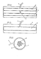
- the sphincter is formed from a band or strip 1 of suitable material such as silicone, on which there have been shaped a number of chambers 2 with hermetic walls, which communicate with each other through small passageways 3, so that the pressure which prevails in all the chambers is practically the same. From one of these chambers a conduit 4 extends to a manually operated suction-impeller pump, which may be of any nature.
- This pump will operate in such a manner that when the valve is depressed the fluid contained inthe chambers 2 is aspirated, emptying them, whereby the two walls of said chambers come against each other. On the other hand when the pump is actuated, the fluid will be forced into the chambers 2, which will be inflated.
- the chambers may comprise one wall 5 of greater flexibility than the other component wall 6 of the strip 1.
- the wall 5 of greater flexibility will be the wall which faces the intestine when placed around the latter.
- the strip or band 1 comprises two rows of chambers 2 aligned in each row, those of one row being staggered with respect to those of the other.
- Fig. 2 there is shown the intercommunication passage 3 between two chambers which is obtained between the walls 5 and 6 which define said chambers.
- the wall 5 will be of great flexibility and may furthermore be elastic in nature.
- the wall 6 may be covered oh one of its faces by a material which facilitates its anchoring to the tissue,which material may consist of teflon, dacron, etc.
- the strip or band of Fig. 1 is arranged in the manner shown in Fig. 3, winding it from the intestine near the stoma and connecting the ends of the strip or band.
- the chambers 2 when they are inflated will reduce to a minimum the central space 7 occupied by the intestine, which will be subjected to pressure, preventing the discharge of solid, liquid and even gaseous elements.
- the pump When the pump is operated, the chambers 2 are deflated, whereby the stoma is freed, permitting the discharge of the elements contained in the intestine.
- FIG. 4 the chambers of each row in accordance with the arrangement of Fig. 1 are now replaced by two hermetic continuous chambers, designated 8 and 9, which are connected together by the passage 3, one of said chambers, in this case the chamber 8, having a conduit 4 for the introduction and removal of the fluid used to inflate and deflate said chambers.
- the strip or band 1 with its chambers 8 and 9 is placed on the outside around the intestine 10, the transverse edges of the strip or band 1 being connected together or else the closed ends of the chamber or chambers, in the event that there is no said band.
- the intestine 10 Upon inflation of the chamber or chambers 8 and 9, the intestine 10 is compressed so as to prevent passage through it. On the other hand, upon deflation of the chamber or chambers 8 and 9, the intestine 10 can expand, permitting passage through it.
- the chambers 8 and 9 may, as shown in Figs. 4 and 5, have an open configuration or else a continuous closed doric configuration, defining a ring which is mounted around the intestine 10.
- the wall of the chambers 8 and 9 which faces the intestine 10 may be of'a flexible and elastic nature, while it is reinforeed on the outside so that it cannot expand outward upon the inflation of the chambers.
- This reinforcement may consist, for instance, of a semi-rigid ring 11, in this way making certain that upon the inflation of the chambers 8 and 9 their expansion will take place in radially inward direction so as to compress the intestine-10.
- the ring 11 may be split in the event that the chambers 8 and 9 have the configuration shown in Figs. 4 and 5 so as to permit the mounting thereof. If the chambers are continuous annular chambers, the ring 11 may be a closed ring.
- the chambers 2, as shown in Figs. 7 to 9, may be of cross section which increases towards their lower part, so that when they are inflated the pressure which may prevail within the intestine presses with greater force against the upper part of the chambers 2 of smaller cross section, whereby the lower part of said chambers will compress the intestine with greater pressure, thus ensuring closure through same.
- the chambers 2 in a simpler configuration, could be developed in the form of vertical cylindrical chambers approximately tangent to the band or strip 1.
Abstract
Description
- The present invention relates to an apparatus intended to obtain continence of the digestive stomas, both abdominal and perineal, and of anal incontinence.
- In order to obtain continence of the diges- tive stomas; an apparatus known under the name of "Maclet (r)" is at present used.
- This apparatus consists of two parts : a magnetic ring and a magnetic plug. The ring is placed around the stoma and the plug within it. This system gives satisfactory results only in colostomies, but not in ileostomies.
- In any event, the said apparatus can today not be applied to the perineal region.
- The objet of the present invention is to provide an apparatus which can be applied in any location of the stomas and in any type of stoma, and which also serves for anal incontinences of any degree.
- The apparatus of the invention is characterized by the fact that it comprises a sphincter formed of a flexible band or strip which has at least two longitudinal rows of staggered chambers or bubbles. These chambers have flexible hermetic walls. In addition, the chambers or bubbles are interconnected with each other. One of the. chambers bears connected to it a conduit through which, by means of a suction- impeller pump of subcutaneous location, a fluid is introduced and extracted, which makes it possible to fill and empty the different chambers or bubbles. When the chambers are filled, they are inflated to their maximum capacity, while when they are evacuated, they are deflated, the two walls of each chamber being prati- cally against each other.
- The strip of band is intended to be placed around the intestine near the stoma, on the outside thereof.
- The band or strip being arranged in the manner indicated, the plunger of the valve is actuated, the pump aspirates the content of the chambers, evacuating them, whereby the decompression of the sphincter is obtained. On the other hand, when the pump is compressed, the fluid is again forced into the chambers filling them and the chambers are inflated, acquiring a given pressure, compressing and closing the digestive tube, thus avoiding the discharge of the solid, liquid or gaseous elements thereof.
- The apparatus of the invention can be provided with an electronic device intended to advise the patient that the pressure within the digestive tube has reached given values which make it advisable to decompress the sphincter.
- The sphincter of the invention may be constructed in different models and dimensions depending on the requirements and use thereof. For example, the band or strip may be of a height of 1 to 1 1/2 cm with a length which varies depending on the ostomy of the patient, for instance between 6 and 12 cm, and 2 mm in thickness. The band or strip will consist of two rows of three chambers, staggered with each other, of a height of 0,5 to 0,75 cm, which are arranged close together. The length of the chambers may vary between 2 and 4 cm. The different chambers communicate with each other, discharging through a tube which extends from one of the chambers, which tube extends up to the chamber of the manually actuated suction-impeller pump.
- Of the two walls which define each chamber, the wall which will be directed towards the wall of the intestine may be of greater flexibility than the outer wall, so that upon the inflation or deflation the chambers experience only a change in the position of the inner wall.
- The inner wall of the chambers, in addition to being flexible, can be elastic.
- The sphincter with its chambers as well as the outlet tube will preferably consist of silicone or some other material of similar properties which is tolerated by the body. Nevertheless, on one of the sides there may be placed a plate of different material which permits better anchoring in the tissue and stimulates fibrosis, such as teflon, dacron, etc.
- In accordance with a variant of the invention, the chambers or bubbles of each row may be extended in longitudinal direction so as to interconnect with each other, defining a single hermetic chamber in each row. Each chamber will be of sufficient size to surround the intestine.
- In accordance with this variant, the sphincter may be formed of a single hermetic chamber or else of two parallel intercommunicating chambers.
- In the case of both one or two parallel chambers, these chambers may have an open doric configuration, in which case the closed ends are close together and attached to each other when the chamber or chambers are placed around the intestine. The chamber or chambers may also be of continuous annular configuration.
- As can be understood, if desired, the sphincter could comprise more than two parallel chambers.
- In accordance with still another variant, a single row of chambers is provided, the chambers being of vertical course and being located close to each other so that when the support band is closed around the intestine, when these chambers are inflated, they contain the intestine within them, closing the passage through same.
- The said chambers may also be of a cross section which decreases from one end to the opposite end, the cross section of all of the chambers increasing in the same direction.
- In order that the nature of the apparatus of the invention may be more easily understood, a more detailed description thereof is given below with reference to the accompanying drawings in which a few possible embodiments are shown, given by way of illustration and not of limitation.
- In the drawings, identical parts or parts of identical function have been designated by the same reference numbers.
- Fig. 1 is an elevation of the band or strip which constitutes the sphincter ;
- Fig. 2 is a cross section on a larger scale, along the line II-II of Fig. 1 ;
- Fig. 3 is a plan view, on a larger scale, of the shaped sphincter ;
- Figs 4 and 5 are plan views of the developed apparatus, constructed in accordance with certain variants of the invention ;
- Fig. 6 shows in profile the apparatus mounted around the intestine, with the chamber or chambers inflated ;
- Fig. 7 is another possible variant of the invention in its extended position ;
- Fig. 8 corresponds to a plan view with the band or strip which serves as support for the chambers closed and the chambers inflated ;
- Fig. 9 is a cross section along the line IX-IX of Fig. 8.
- As can be noted from Fig. 1, the sphincter is formed from a band or
strip 1 of suitable material such as silicone, on which there have been shaped a number ofchambers 2 with hermetic walls, which communicate with each other throughsmall passageways 3, so that the pressure which prevails in all the chambers is practically the same. From one of these chambers aconduit 4 extends to a manually operated suction-impeller pump, which may be of any nature. - This pump will operate in such a manner that when the valve is depressed the fluid contained
inthe chambers 2 is aspirated, emptying them, whereby the two walls of said chambers come against each other. On the other hand when the pump is actuated, the fluid will be forced into thechambers 2, which will be inflated. - As shown in Fig. 2, the chambers may comprise one
wall 5 of greater flexibility than theother component wall 6 of thestrip 1. Thewall 5 of greater flexibility will be the wall which faces the intestine when placed around the latter. - In the example described, the strip or
band 1 comprises two rows ofchambers 2 aligned in each row, those of one row being staggered with respect to those of the other. In Fig. 2 there is shown theintercommunication passage 3 between two chambers which is obtained between thewalls - The
wall 5 will be of great flexibility and may furthermore be elastic in nature. - The
wall 6 may be covered oh one of its faces by a material which facilitates its anchoring to the tissue,which material may consist of teflon, dacron, etc. - The strip or band of Fig. 1 is arranged in the manner shown in Fig. 3, winding it from the intestine near the stoma and connecting the ends of the strip or band. In this way, the
chambers 2 when they are inflated will reduce to a minimum thecentral space 7 occupied by the intestine, which will be subjected to pressure, preventing the discharge of solid, liquid and even gaseous elements. When the pump is operated, thechambers 2 are deflated, whereby the stoma is freed, permitting the discharge of the elements contained in the intestine. - As already indicated, there may be placed in the intestine near the stoma and in anintramural location, an electronic device which advises the patient when a givenpressure at which decompression of the sphincter is advisable has been reached.
- Referring now to Fig. 4, the chambers of each row in accordance with the arrangement of Fig. 1 are now replaced by two hermetic continuous chambers, designated 8 and 9, which are connected together by the
passage 3, one of said chambers, in this case thechamber 8, having aconduit 4 for the introduction and removal of the fluid used to inflate and deflate said chambers. - In the case of Fig. 5, there is only a
single chamber 8 from which the inlet andoutlet conduit 4 extends. - As can be noted from Fig. 6, the strip or
band 1 with itschambers intestine 10, the transverse edges of the strip orband 1 being connected together or else the closed ends of the chamber or chambers, in the event that there is no said band. - Upon inflation of the chamber or
chambers intestine 10 is compressed so as to prevent passage through it. On the other hand, upon deflation of the chamber orchambers intestine 10 can expand, permitting passage through it. - The
chambers intestine 10. - The wall of the
chambers intestine 10 may be of'a flexible and elastic nature, while it is reinforeed on the outside so that it cannot expand outward upon the inflation of the chambers. This reinforcement may consist, for instance, of a semi-rigid ring 11, in this way making certain that upon the inflation of thechambers - The ring 11 may be split in the event that the
chambers - The
chambers 2, as shown in Figs. 7 to 9, may be of cross section which increases towards their lower part, so that when they are inflated the pressure which may prevail within the intestine presses with greater force against the upper part of thechambers 2 of smaller cross section, whereby the lower part of said chambers will compress the intestine with greater pressure, thus ensuring closure through same. - The
chambers 2, in a simpler configuration, could be developed in the form of vertical cylindrical chambers approximately tangent to the band orstrip 1. - Having sufficiently described the nature of the invention as well as the manner of reducing it to practice, it should be pointed out that the arrangements indicated above are capable of modifications in detail insofar as they do not change its fundamental principle.
Claims (11)
Priority Applications (1)
| Application Number | Priority Date | Filing Date | Title |
|---|---|---|---|
| AT80401528T ATE6986T1 (en) | 1979-10-30 | 1980-10-28 | DEVICE FOR CLOSURE OF ARTIFICIAL OUTLETS AND ANAL INCONTINENCE. |
Applications Claiming Priority (6)
| Application Number | Priority Date | Filing Date | Title |
|---|---|---|---|
| ES485537A ES485537A1 (en) | 1979-10-30 | 1979-10-30 | Prohibiting device for digestion system stoma and anus incontinence |
| ES485537 | 1979-10-30 | ||
| ES491638 | 1980-05-20 | ||
| ES491637A ES8103643A2 (en) | 1980-05-20 | 1980-05-20 | Apparatus for the continence of digestive stomes and anal incontinence. (Machine-translation by Google Translate, not legally binding) |
| ES491638A ES8103644A2 (en) | 1980-05-20 | 1980-05-20 | Apparatus for the continence of digestive stomes and anal incontinence. (Machine-translation by Google Translate, not legally binding) |
| ES491637 | 1980-05-20 |
Publications (2)
| Publication Number | Publication Date |
|---|---|
| EP0028962A1 true EP0028962A1 (en) | 1981-05-20 |
| EP0028962B1 EP0028962B1 (en) | 1984-04-11 |
Family
ID=27240784
Family Applications (1)
| Application Number | Title | Priority Date | Filing Date |
|---|---|---|---|
| EP80401528A Expired EP0028962B1 (en) | 1979-10-30 | 1980-10-28 | Apparatus for the continence of digestive stomas and anal incontinence |
Country Status (12)
| Country | Link |
|---|---|
| US (1) | US4399809A (en) |
| EP (1) | EP0028962B1 (en) |
| AR (1) | AR221189A1 (en) |
| AU (1) | AU539132B2 (en) |
| BR (1) | BR8006971A (en) |
| CA (1) | CA1156003A (en) |
| DE (1) | DE3067463D1 (en) |
| DK (1) | DK458780A (en) |
| FI (1) | FI803346L (en) |
| IL (1) | IL61256A (en) |
| NO (1) | NO803232L (en) |
| PT (1) | PT71950B (en) |
Cited By (14)
| Publication number | Priority date | Publication date | Assignee | Title |
|---|---|---|---|---|
| EP0093507A1 (en) * | 1982-04-23 | 1983-11-09 | National Aeronautics And Space Administration | Prosthetic occlusive device for an internal passageway |
| FR2602415A1 (en) * | 1986-05-08 | 1988-02-12 | Baron Howard | CLAMP AND METHOD FOR SHUTTING THE LIGHT OF A VESSEL OR OTHER CONDUCT FROM THE HUMAN BODY |
| WO2005099618A2 (en) * | 2004-04-15 | 2005-10-27 | Universitätsklinikum Freiburg | Implantable muscle closing prosthesis system, in particular in the anal channel area |
| WO2007122505A2 (en) * | 2006-04-25 | 2007-11-01 | Beta Micropump Partners Llc | A cuff for a lumen |
| FR2922097A1 (en) * | 2007-10-16 | 2009-04-17 | Cie Euro Etude Rech Paroscopie | Implantable surgical ring e.g. bi-cuff gastric ring, for e.g. patient's stomach, has locking chambers attached with each other and formed in free bidirectional fluidic communication or devoid of fluidic communication units between chambers |
| FR2929838A1 (en) * | 2008-04-14 | 2009-10-16 | Cie Euro Etude Rech Paroscopie | GASTRIC RING WITH MEMBRANE BRIDGE |
| FR2929841A1 (en) * | 2008-04-14 | 2009-10-16 | Cie Euro Etude Rech Paroscopie | IMPLANTABLE SURGICAL RING WITH MONOBLOC HOSE |
| FR2929840A1 (en) * | 2008-04-14 | 2009-10-16 | Cie Euro Etude Rech Paroscopie | UNDERGROUND LOCK RING |
| FR2929842A1 (en) * | 2008-04-14 | 2009-10-16 | Cie Euro Etude Rech Paroscopie | GASTRIC RING WITH TILT POCKETS |
| FR2929839A1 (en) * | 2008-04-14 | 2009-10-16 | Cie Euro Etude Rech Paroscopie | GASTRIC RING COMPRISING A MONOBLOC BELT |
| US8343032B2 (en) | 2003-07-25 | 2013-01-01 | Wolfgang Lechner | Controllable gastric band |
| IT201900013326A1 (en) * | 2019-07-30 | 2021-01-30 | Giuseppe Salamone | ARTIFICIAL SPHINTER FOR THE CLOSURE OF STOMIES |
| IT202100012419A1 (en) | 2021-05-14 | 2022-11-14 | Evolving Healthcare S R L | ARTIFICIAL SPHINCTER FOR THE CLOSURE OF STOMAS |
| IT202100012566A1 (en) | 2021-05-14 | 2022-11-14 | Evolving Healthcare S R L | SURGICAL INSTRUMENT FOR THE POSITIONING OF AN ARTIFICIAL SPHINCTER FOR THE CLOSURE OF STOMAS AND ASSEMBLY INCLUDING THE INSTRUMENT |
Families Citing this family (95)
| Publication number | Priority date | Publication date | Assignee | Title |
|---|---|---|---|---|
| US4551862A (en) * | 1982-12-15 | 1985-11-12 | Haber Terry M | Prosthetic sphincter |
| US4584990A (en) * | 1984-10-02 | 1986-04-29 | Habley Medical Technology Corporation | Prosthetic sphincter having a diametric occlusion geometry |
| SE448812B (en) * | 1985-02-01 | 1987-03-23 | Astra Meditec Ab | SURGICAL DEVICE FOR CONNECTING THE TAGS OF A PATIENT |
| US4727887A (en) * | 1985-07-08 | 1988-03-01 | Habley Medical Technology Corporation | Hypodermic manometer |
| US4709690A (en) * | 1986-04-21 | 1987-12-01 | Habley Medical Technology Corporation | Implantable blood flow and occlusion pressure sensing sphincteric system |
| US4770175A (en) * | 1986-10-22 | 1988-09-13 | Western Clinical Engineering Ltd. | Occlusive cuff |
| US4989615A (en) * | 1988-01-12 | 1991-02-05 | International Biomedics, Inc. | Apparatus for non-invasive monitoring of uterine contractions |
| US5057117A (en) * | 1989-04-27 | 1991-10-15 | The Research Foundation Of State University Of New York | Method and apparatus for hemostasis and compartmentalization of a bleeding internal bodily organ |
| SE464558B (en) * | 1990-03-22 | 1991-05-13 | Hepar Ab | IMPLANTABLE DEVICE FOR SUSPENSION OF A CHANNEL IN THE BODY OF A LIVE BEING |
| US5312431A (en) * | 1991-09-30 | 1994-05-17 | Abatis Medical Technologies Limited | Occlusive cuff |
| US5649954A (en) * | 1991-09-30 | 1997-07-22 | Mcewen; James A. | Tourniquet cuff system |
| US5224490A (en) * | 1991-10-04 | 1993-07-06 | Graphic Controls Corporation | Disposable tocodynamometer with self-adjusting bellows |
| US6638208B1 (en) | 1998-09-15 | 2003-10-28 | Infinite Biomedical Technologies, Llc | Intraurethral continent prothesis |
| US6319237B1 (en) * | 1999-04-23 | 2001-11-20 | Icd Labs, Inc. | Urinary sphincter control device |
| US6464628B1 (en) | 1999-08-12 | 2002-10-15 | Obtech Medical Ag | Mechanical anal incontinence |
| DE60128971T2 (en) | 2000-02-10 | 2008-02-07 | Potencia Medical Ag | Mechanical device for impotence treatment |
| AU777577B2 (en) * | 2000-02-10 | 2004-10-21 | Implantica Patent Ltd. | Anal incontinence treatment with controlled wireless energy supply |
| AU2001232586A1 (en) | 2000-02-14 | 2001-07-09 | Potencia Medical Ag | Penile prosthesis |
| WO2003075256A1 (en) * | 2002-03-05 | 2003-09-12 | Nec Corporation | Image display and its control method |
| US7338433B2 (en) * | 2002-08-13 | 2008-03-04 | Allergan, Inc. | Remotely adjustable gastric banding method |
| DE60331457D1 (en) | 2002-08-28 | 2010-04-08 | Allergan Inc | TEMPTING MAGNETIC BANDING DEVICE |
| US6805662B2 (en) * | 2003-02-18 | 2004-10-19 | Polyzen, Inc. | Urinary incontinence control device and method of use |
| WO2005037055A2 (en) * | 2003-09-15 | 2005-04-28 | Inamed Medical Products Corporation | Implantable device fastening system and methods of use |
| US20050070937A1 (en) * | 2003-09-30 | 2005-03-31 | Jambor Kristin L. | Segmented gastric band |
| ES2375930T5 (en) | 2004-01-23 | 2014-10-31 | Apollo Endosurgery, Inc. | Implantable device fixation system |
| JP2007527279A (en) | 2004-01-23 | 2007-09-27 | アラーガン、インコーポレイテッド | One-piece adjustable gastric band that can be fixed removably |
| ES2333024T3 (en) | 2004-03-08 | 2010-02-16 | Allergan Medical S.A. | CLOSURE SYSTEM FOR TUBULAR ORGANS. |
| ATE517652T1 (en) | 2004-03-18 | 2011-08-15 | Allergan Inc | DEVICE FOR ADJUSTING THE VOLUME OF INTRAGASTRAL BALLOONS |
| US7047832B1 (en) * | 2004-11-08 | 2006-05-23 | Oporgenics, Inc., Llc | Apparatus for measuring gas exchange |
| US7775966B2 (en) | 2005-02-24 | 2010-08-17 | Ethicon Endo-Surgery, Inc. | Non-invasive pressure measurement in a fluid adjustable restrictive device |
| US7927270B2 (en) | 2005-02-24 | 2011-04-19 | Ethicon Endo-Surgery, Inc. | External mechanical pressure sensor for gastric band pressure measurements |
| US7775215B2 (en) | 2005-02-24 | 2010-08-17 | Ethicon Endo-Surgery, Inc. | System and method for determining implanted device positioning and obtaining pressure data |
| US8066629B2 (en) | 2005-02-24 | 2011-11-29 | Ethicon Endo-Surgery, Inc. | Apparatus for adjustment and sensing of gastric band pressure |
| US7699770B2 (en) | 2005-02-24 | 2010-04-20 | Ethicon Endo-Surgery, Inc. | Device for non-invasive measurement of fluid pressure in an adjustable restriction device |
| US8016744B2 (en) | 2005-02-24 | 2011-09-13 | Ethicon Endo-Surgery, Inc. | External pressure-based gastric band adjustment system and method |
| US7658196B2 (en) | 2005-02-24 | 2010-02-09 | Ethicon Endo-Surgery, Inc. | System and method for determining implanted device orientation |
| US8251888B2 (en) | 2005-04-13 | 2012-08-28 | Mitchell Steven Roslin | Artificial gastric valve |
| US8043206B2 (en) | 2006-01-04 | 2011-10-25 | Allergan, Inc. | Self-regulating gastric band with pressure data processing |
| US7798954B2 (en) | 2006-01-04 | 2010-09-21 | Allergan, Inc. | Hydraulic gastric band with collapsible reservoir |
| US8152710B2 (en) | 2006-04-06 | 2012-04-10 | Ethicon Endo-Surgery, Inc. | Physiological parameter analysis for an implantable restriction device and a data logger |
| US8870742B2 (en) | 2006-04-06 | 2014-10-28 | Ethicon Endo-Surgery, Inc. | GUI for an implantable restriction device and a data logger |
| US7828715B2 (en) | 2006-06-29 | 2010-11-09 | Ams Research Corporation | Method of treating anal incontinence |
| JP2010514538A (en) * | 2007-01-03 | 2010-05-06 | エーエムエス リサーチ コーポレイション | Stool attachment method for fecal incontinence and related devices |
| JP2010538772A (en) * | 2007-09-20 | 2010-12-16 | コンティネンス コントロール システムズ インターナショナル プロプライエタリー リミテッド | System, method and apparatus for controlling enterostomy |
| US8992409B2 (en) | 2007-10-11 | 2015-03-31 | Peter Forsell | Method for controlling flow in a bodily organ |
| SI2211768T1 (en) | 2007-10-11 | 2021-11-30 | Implantica Patent Ltd. | Apparatus for controlling flow in a bodily organ |
| US8696543B2 (en) | 2007-10-11 | 2014-04-15 | Kirk Promotion Ltd. | Method for controlling flow of intestinal contents in a patient's intestines |
| US8795153B2 (en) * | 2007-10-11 | 2014-08-05 | Peter Forsell | Method for treating female sexual dysfunction |
| US8187163B2 (en) | 2007-12-10 | 2012-05-29 | Ethicon Endo-Surgery, Inc. | Methods for implanting a gastric restriction device |
| US20090156891A1 (en) * | 2007-12-12 | 2009-06-18 | Ams Research Corporation | Prolapse and Perineal Repair Concepts |
| US8100870B2 (en) | 2007-12-14 | 2012-01-24 | Ethicon Endo-Surgery, Inc. | Adjustable height gastric restriction devices and methods |
| US8142452B2 (en) | 2007-12-27 | 2012-03-27 | Ethicon Endo-Surgery, Inc. | Controlling pressure in adjustable restriction devices |
| US8377079B2 (en) | 2007-12-27 | 2013-02-19 | Ethicon Endo-Surgery, Inc. | Constant force mechanisms for regulating restriction devices |
| US8192350B2 (en) | 2008-01-28 | 2012-06-05 | Ethicon Endo-Surgery, Inc. | Methods and devices for measuring impedance in a gastric restriction system |
| US8337389B2 (en) | 2008-01-28 | 2012-12-25 | Ethicon Endo-Surgery, Inc. | Methods and devices for diagnosing performance of a gastric restriction system |
| US8591395B2 (en) | 2008-01-28 | 2013-11-26 | Ethicon Endo-Surgery, Inc. | Gastric restriction device data handling devices and methods |
| EP2240138B1 (en) | 2008-01-29 | 2021-07-21 | Implantica Patent Ltd. | Apparatus for treating obesity |
| US7844342B2 (en) | 2008-02-07 | 2010-11-30 | Ethicon Endo-Surgery, Inc. | Powering implantable restriction systems using light |
| US8221439B2 (en) | 2008-02-07 | 2012-07-17 | Ethicon Endo-Surgery, Inc. | Powering implantable restriction systems using kinetic motion |
| US8114345B2 (en) | 2008-02-08 | 2012-02-14 | Ethicon Endo-Surgery, Inc. | System and method of sterilizing an implantable medical device |
| US8057492B2 (en) | 2008-02-12 | 2011-11-15 | Ethicon Endo-Surgery, Inc. | Automatically adjusting band system with MEMS pump |
| US8591532B2 (en) | 2008-02-12 | 2013-11-26 | Ethicon Endo-Sugery, Inc. | Automatically adjusting band system |
| US8034065B2 (en) | 2008-02-26 | 2011-10-11 | Ethicon Endo-Surgery, Inc. | Controlling pressure in adjustable restriction devices |
| US8233995B2 (en) | 2008-03-06 | 2012-07-31 | Ethicon Endo-Surgery, Inc. | System and method of aligning an implantable antenna |
| US8187162B2 (en) | 2008-03-06 | 2012-05-29 | Ethicon Endo-Surgery, Inc. | Reorientation port |
| WO2009149108A1 (en) | 2008-06-02 | 2009-12-10 | Loma Vista Medical, Inc. | Inflatable medical devices |
| EP2362762A1 (en) | 2008-10-06 | 2011-09-07 | Allergan Medical Sàrl | Mechanical gastric band with cushions |
| US8600510B2 (en) | 2008-10-10 | 2013-12-03 | Milux Holding Sa | Apparatus, system and operation method for the treatment of female sexual dysfunction |
| WO2010042006A1 (en) | 2008-10-10 | 2010-04-15 | Milux Holding S.A. | Heart help method |
| EP2349025B1 (en) * | 2008-10-10 | 2015-09-16 | Kirk Promotion LTD. | A system, an apparatus, and a method for treating a sexual dysfunctional female patient |
| US20100185049A1 (en) | 2008-10-22 | 2010-07-22 | Allergan, Inc. | Dome and screw valves for remotely adjustable gastric banding systems |
| HUE045768T2 (en) | 2009-07-14 | 2020-01-28 | Braun Medical | Stomal cover |
| US9314365B2 (en) | 2009-07-14 | 2016-04-19 | B. Braun Medical Sas | Ostomy port gas release mechanism |
| US8900116B2 (en) * | 2009-07-14 | 2014-12-02 | Stimatix Gi Ltd. | Inflatable stomal implant |
| US8758221B2 (en) | 2010-02-24 | 2014-06-24 | Apollo Endosurgery, Inc. | Source reservoir with potential energy for remotely adjustable gastric banding system |
| US8840541B2 (en) | 2010-02-25 | 2014-09-23 | Apollo Endosurgery, Inc. | Pressure sensing gastric banding system |
| US10434309B2 (en) * | 2010-04-12 | 2019-10-08 | Peter Forsell | System for treating a patient having an intestinal disorder |
| US9044298B2 (en) | 2010-04-29 | 2015-06-02 | Apollo Endosurgery, Inc. | Self-adjusting gastric band |
| US9028394B2 (en) | 2010-04-29 | 2015-05-12 | Apollo Endosurgery, Inc. | Self-adjusting mechanical gastric band |
| US20110270024A1 (en) | 2010-04-29 | 2011-11-03 | Allergan, Inc. | Self-adjusting gastric band having various compliant components |
| US20110270025A1 (en) | 2010-04-30 | 2011-11-03 | Allergan, Inc. | Remotely powered remotely adjustable gastric band system |
| US8517915B2 (en) | 2010-06-10 | 2013-08-27 | Allergan, Inc. | Remotely adjustable gastric banding system |
| US20120059216A1 (en) | 2010-09-07 | 2012-03-08 | Allergan, Inc. | Remotely adjustable gastric banding system |
| US8961393B2 (en) | 2010-11-15 | 2015-02-24 | Apollo Endosurgery, Inc. | Gastric band devices and drive systems |
| CA3028172C (en) | 2011-01-18 | 2020-12-22 | Loma Vista Medical, Inc. | Inflatable medical devices |
| US8876694B2 (en) | 2011-12-07 | 2014-11-04 | Apollo Endosurgery, Inc. | Tube connector with a guiding tip |
| US8961394B2 (en) | 2011-12-20 | 2015-02-24 | Apollo Endosurgery, Inc. | Self-sealing fluid joint for use with a gastric band |
| JP2015515905A (en) | 2012-05-10 | 2015-06-04 | スティマティックス ジーアイ リミテッド | Surgery instruments |
| WO2014063039A1 (en) | 2012-10-18 | 2014-04-24 | Loma Vista Medical, Inc. | Reinforced inflatable medical devices |
| US11291579B2 (en) | 2013-05-09 | 2022-04-05 | B. Braun Medical Sas | Gas filter and release for ostomy appliance |
| USD783814S1 (en) | 2013-12-09 | 2017-04-11 | B. Braun Medical Sas | Adapter for flatus release |
| USD796029S1 (en) | 2013-12-09 | 2017-08-29 | B. Braun Medical Sas | Colostomy appliance |
| ES1196036Y (en) * | 2017-10-18 | 2018-01-19 | Servicio Andaluz De Salud | Continent Colostomy Device |
| USD1012280S1 (en) | 2018-11-30 | 2024-01-23 | B. Braun Medical Sas | Ostomy device assembly |
| WO2022258832A1 (en) * | 2021-06-11 | 2022-12-15 | Mueller Jan Erik | Ostomy system for a controlled discharge of stool |
Citations (11)
| Publication number | Priority date | Publication date | Assignee | Title |
|---|---|---|---|---|
| US2455859A (en) * | 1946-05-13 | 1948-12-07 | Frederic E B Foley | Artificial sphincter and method |
| US2699781A (en) * | 1953-12-31 | 1955-01-18 | Koch Frederick Edward | Self-carried urinal for male use |
| DE1541262A1 (en) * | 1966-06-23 | 1969-06-19 | Gruenert Dr Med Rolf Dieter | Device for closing and opening a natural or artificially created passage way in human or animal bodies |
| FR2041444A5 (en) * | 1969-04-24 | 1971-01-29 | Crouzet & Cie | |
| US3744063A (en) * | 1971-10-12 | 1973-07-10 | Kendall & Co | Artifical sphincter for controlling urinary incontinence |
| US3750194A (en) * | 1971-03-16 | 1973-08-07 | Fairchild Industries | Apparatus and method for reversibly closing a natural or implanted body passage |
| US3863622A (en) * | 1973-01-09 | 1975-02-04 | Robert Enno Buuck | Incontinence system and methods of implanting and using same |
| FR2251302A1 (en) * | 1973-11-16 | 1975-06-13 | Anvar | Externally controlled artificial sphincter - external electromagnet actuates motor controlling valve balloon inflation |
| FR2373272A1 (en) * | 1976-12-07 | 1978-07-07 | Inst Nat Sante Rech Med | Artificial sphincter for urinal incontinence - has ring around urethra to be inflated and deflated by two press bulbs operating single valve |
| DD131619A1 (en) * | 1977-06-13 | 1978-07-12 | Hans Bellmann | FULLY CONTINENTAL KINGDOM CLOSING MUSCLE |
| DE2806405A1 (en) * | 1977-02-28 | 1978-08-31 | Codman & Shurtleff | ARTIFICIAL MECHANICAL SPHINKTER |
Family Cites Families (4)
| Publication number | Priority date | Publication date | Assignee | Title |
|---|---|---|---|---|
| US3049125A (en) * | 1960-03-28 | 1962-08-14 | Kriwkowitsch George | Nose packing device |
| FR2204388B1 (en) * | 1972-10-25 | 1978-11-10 | Aronson T | |
| US4141364A (en) * | 1977-03-18 | 1979-02-27 | Jorge Schultze | Expandable endotracheal or urethral tube |
| US4183102A (en) * | 1977-09-08 | 1980-01-15 | Jacques Guiset | Inflatable prosthetic device for lining a body duct |
-
1980
- 1980-10-10 CA CA000362252A patent/CA1156003A/en not_active Expired
- 1980-10-10 AU AU63136/80A patent/AU539132B2/en not_active Ceased
- 1980-10-13 IL IL61256A patent/IL61256A/en unknown
- 1980-10-22 PT PT71950A patent/PT71950B/en unknown
- 1980-10-23 AR AR282985A patent/AR221189A1/en active
- 1980-10-24 US US06/200,479 patent/US4399809A/en not_active Expired - Lifetime
- 1980-10-24 FI FI803346A patent/FI803346L/en not_active Application Discontinuation
- 1980-10-28 EP EP80401528A patent/EP0028962B1/en not_active Expired
- 1980-10-28 DE DE8080401528T patent/DE3067463D1/en not_active Expired
- 1980-10-29 BR BR8006971A patent/BR8006971A/en unknown
- 1980-10-29 DK DK458780A patent/DK458780A/en not_active Application Discontinuation
- 1980-10-29 NO NO803232A patent/NO803232L/en unknown
Patent Citations (11)
| Publication number | Priority date | Publication date | Assignee | Title |
|---|---|---|---|---|
| US2455859A (en) * | 1946-05-13 | 1948-12-07 | Frederic E B Foley | Artificial sphincter and method |
| US2699781A (en) * | 1953-12-31 | 1955-01-18 | Koch Frederick Edward | Self-carried urinal for male use |
| DE1541262A1 (en) * | 1966-06-23 | 1969-06-19 | Gruenert Dr Med Rolf Dieter | Device for closing and opening a natural or artificially created passage way in human or animal bodies |
| FR2041444A5 (en) * | 1969-04-24 | 1971-01-29 | Crouzet & Cie | |
| US3750194A (en) * | 1971-03-16 | 1973-08-07 | Fairchild Industries | Apparatus and method for reversibly closing a natural or implanted body passage |
| US3744063A (en) * | 1971-10-12 | 1973-07-10 | Kendall & Co | Artifical sphincter for controlling urinary incontinence |
| US3863622A (en) * | 1973-01-09 | 1975-02-04 | Robert Enno Buuck | Incontinence system and methods of implanting and using same |
| FR2251302A1 (en) * | 1973-11-16 | 1975-06-13 | Anvar | Externally controlled artificial sphincter - external electromagnet actuates motor controlling valve balloon inflation |
| FR2373272A1 (en) * | 1976-12-07 | 1978-07-07 | Inst Nat Sante Rech Med | Artificial sphincter for urinal incontinence - has ring around urethra to be inflated and deflated by two press bulbs operating single valve |
| DE2806405A1 (en) * | 1977-02-28 | 1978-08-31 | Codman & Shurtleff | ARTIFICIAL MECHANICAL SPHINKTER |
| DD131619A1 (en) * | 1977-06-13 | 1978-07-12 | Hans Bellmann | FULLY CONTINENTAL KINGDOM CLOSING MUSCLE |
Cited By (28)
| Publication number | Priority date | Publication date | Assignee | Title |
|---|---|---|---|---|
| EP0093507A1 (en) * | 1982-04-23 | 1983-11-09 | National Aeronautics And Space Administration | Prosthetic occlusive device for an internal passageway |
| FR2602415A1 (en) * | 1986-05-08 | 1988-02-12 | Baron Howard | CLAMP AND METHOD FOR SHUTTING THE LIGHT OF A VESSEL OR OTHER CONDUCT FROM THE HUMAN BODY |
| US8343032B2 (en) | 2003-07-25 | 2013-01-01 | Wolfgang Lechner | Controllable gastric band |
| WO2005099618A2 (en) * | 2004-04-15 | 2005-10-27 | Universitätsklinikum Freiburg | Implantable muscle closing prosthesis system, in particular in the anal channel area |
| WO2005099618A3 (en) * | 2004-04-15 | 2006-01-12 | Universitaetsklinikum Freiburg | Implantable muscle closing prosthesis system, in particular in the anal channel area |
| WO2007122505A2 (en) * | 2006-04-25 | 2007-11-01 | Beta Micropump Partners Llc | A cuff for a lumen |
| WO2007122505A3 (en) * | 2006-04-25 | 2007-12-27 | Beta Micropump Partners Llc | A cuff for a lumen |
| FR2922097A1 (en) * | 2007-10-16 | 2009-04-17 | Cie Euro Etude Rech Paroscopie | Implantable surgical ring e.g. bi-cuff gastric ring, for e.g. patient's stomach, has locking chambers attached with each other and formed in free bidirectional fluidic communication or devoid of fluidic communication units between chambers |
| WO2009090334A3 (en) * | 2007-10-16 | 2009-09-11 | Compagnie Europeenne D'etude Et De Recherche De Dispositifs Pour L'implantation Par Laparoscopie | Dual balloon gastric ring |
| US8721522B2 (en) | 2007-10-16 | 2014-05-13 | Compagnie Europeenne d'Etude et de Recherche de Dispositifs l'Implantation par Laparoscopie | Dual balloon gastric ring |
| RU2481806C2 (en) * | 2007-10-16 | 2013-05-20 | Компани Эропеен Д'Этюд Э Де Решерш Де Диспозитиф Пур Л'Имплантасьон Пар Лапароскопи | Two-balloon stomach ring |
| WO2009136123A2 (en) * | 2008-04-14 | 2009-11-12 | Compagnie Europeenne D'etude Et De Recherche De Dispositifs Pour L'implantation Par Laparoscopie | Ring having subsurface bolt |
| WO2009136120A3 (en) * | 2008-04-14 | 2010-02-18 | Compagnie Europeenne D'etude Et De Recherche De Dispositifs Pour L'implantation Par Laparoscopie | Gastric ring including a one-piece belt |
| WO2009136122A2 (en) * | 2008-04-14 | 2009-11-12 | Compagnie Europeenne D'etude Et De Recherche De Dispositifs Pour L'implantation Par Laparoscopie | Implantable surgical ring with single hose |
| FR2929842A1 (en) * | 2008-04-14 | 2009-10-16 | Cie Euro Etude Rech Paroscopie | GASTRIC RING WITH TILT POCKETS |
| WO2009136119A2 (en) | 2008-04-14 | 2009-11-12 | Compagnie Europeenne D'etude Et De Recherche De Dispositifs Pour L'implantation Par Laparoscopie | Gastric ring with membranous bridge |
| WO2009136126A2 (en) | 2008-04-14 | 2009-11-12 | Compagnie Europeenne D'etude Et De Recherche De Dispositifs Pour L'implantation Par Laparoscopie | Gastric ring with switching pockets |
| WO2009136123A3 (en) * | 2008-04-14 | 2010-01-21 | Compagnie Europeenne D'etude Et De Recherche De Dispositifs Pour L'implantation Par Laparoscopie | Ring having subsurface bolt |
| WO2009136122A3 (en) * | 2008-04-14 | 2010-01-21 | Compagnie Europeenne D'etude Et De Recherche De Dispositifs Pour L'implantation Par Laparoscopie | Implantable surgical ring with single hose |
| WO2009136119A3 (en) * | 2008-04-14 | 2010-02-18 | Compagnie Europeenne D'etude Et De Recherche De Dispositifs Pour L'implantation Par Laparoscopie | Gastric ring with membranous bridge |
| FR2929839A1 (en) * | 2008-04-14 | 2009-10-16 | Cie Euro Etude Rech Paroscopie | GASTRIC RING COMPRISING A MONOBLOC BELT |
| WO2009136126A3 (en) * | 2008-04-14 | 2010-02-18 | Compagnie Europeenne D'etude Et De Recherche De Dispositifs Pour L'implantation Par Laparoscopie | Gastric ring with switching pockets |
| FR2929840A1 (en) * | 2008-04-14 | 2009-10-16 | Cie Euro Etude Rech Paroscopie | UNDERGROUND LOCK RING |
| FR2929841A1 (en) * | 2008-04-14 | 2009-10-16 | Cie Euro Etude Rech Paroscopie | IMPLANTABLE SURGICAL RING WITH MONOBLOC HOSE |
| FR2929838A1 (en) * | 2008-04-14 | 2009-10-16 | Cie Euro Etude Rech Paroscopie | GASTRIC RING WITH MEMBRANE BRIDGE |
| IT201900013326A1 (en) * | 2019-07-30 | 2021-01-30 | Giuseppe Salamone | ARTIFICIAL SPHINTER FOR THE CLOSURE OF STOMIES |
| IT202100012419A1 (en) | 2021-05-14 | 2022-11-14 | Evolving Healthcare S R L | ARTIFICIAL SPHINCTER FOR THE CLOSURE OF STOMAS |
| IT202100012566A1 (en) | 2021-05-14 | 2022-11-14 | Evolving Healthcare S R L | SURGICAL INSTRUMENT FOR THE POSITIONING OF AN ARTIFICIAL SPHINCTER FOR THE CLOSURE OF STOMAS AND ASSEMBLY INCLUDING THE INSTRUMENT |
Also Published As
| Publication number | Publication date |
|---|---|
| PT71950A (en) | 1980-11-01 |
| AU6313680A (en) | 1981-04-16 |
| PT71950B (en) | 1981-09-17 |
| BR8006971A (en) | 1981-05-05 |
| DE3067463D1 (en) | 1984-05-17 |
| CA1156003A (en) | 1983-11-01 |
| FI803346L (en) | 1981-05-01 |
| EP0028962B1 (en) | 1984-04-11 |
| DK458780A (en) | 1981-05-01 |
| AU539132B2 (en) | 1984-09-13 |
| US4399809A (en) | 1983-08-23 |
| IL61256A (en) | 1984-02-29 |
| NO803232L (en) | 1981-05-04 |
| AR221189A1 (en) | 1980-12-30 |
Similar Documents
| Publication | Publication Date | Title |
|---|---|---|
| EP0028962A1 (en) | Apparatus for the continence of digestive stomas and anal incontinence | |
| US7572218B2 (en) | Implantable muscle closing prosthesis system, in particular in the anal channel area | |
| US11896471B2 (en) | Biased artificial sphincter cuff | |
| US4799928A (en) | Urological device | |
| US4428365A (en) | Anti-incontinent prostheses | |
| CA2483335C (en) | Segmented gastric band | |
| WO1987001274A1 (en) | Closure for ostomy device | |
| US4096853A (en) | Device for the introduction of contrast medium into an anus praeter | |
| US3376868A (en) | Surgical evacuator device | |
| US4694827A (en) | Inflatable gastric device for treating obesity and method of using the same | |
| US5593443A (en) | Prosthetic anal sphincter | |
| EP1649839B1 (en) | Stoma plug | |
| EP0372311B1 (en) | Implantable artificial bladder system | |
| US20110306823A1 (en) | Closing system for a natural or artificial anus | |
| GB2099304A (en) | Incontinence control devices | |
| US5041136A (en) | Implantable artificial soft bladder system | |
| US20070249893A1 (en) | Cuff for a lumen | |
| JPS61268247A (en) | Prosthetic sphincter apparatus | |
| EP0506920B1 (en) | Urinary control with inflatable seal | |
| FR2373272A1 (en) | Artificial sphincter for urinal incontinence - has ring around urethra to be inflated and deflated by two press bulbs operating single valve | |
| US2839050A (en) | Device for measuring the tonus of the muscular system of the floor of the vagina, pelvis and adjacent areas | |
| US4178915A (en) | Selectively operatable blocking device for tubular body organs | |
| WO2002039959A8 (en) | Receptacle | |
| CN207575255U (en) | Male sex organ protect component and male sex organ protective device | |
| CN111328273B (en) | Occlusion cuff and implantable occlusion system including such cuff |
Legal Events
| Date | Code | Title | Description |
|---|---|---|---|
| PUAI | Public reference made under article 153(3) epc to a published international application that has entered the european phase |
Free format text: ORIGINAL CODE: 0009012 |
|
| AK | Designated contracting states |
Designated state(s): AT BE CH DE FR GB IT LU NL SE |
|
| 17P | Request for examination filed |
Effective date: 19811104 |
|
| ITF | It: translation for a ep patent filed |
Owner name: STUDIO TORTA SOCIETA' SEMPLICE |
|
| GRAA | (expected) grant |
Free format text: ORIGINAL CODE: 0009210 |
|
| AK | Designated contracting states |
Designated state(s): AT BE CH DE FR GB IT LI LU NL SE |
|
| PG25 | Lapsed in a contracting state [announced via postgrant information from national office to epo] |
Ref country code: NL Effective date: 19840411 Ref country code: LI Effective date: 19840411 Ref country code: CH Effective date: 19840411 Ref country code: BE Effective date: 19840411 Ref country code: AT Effective date: 19840411 |
|
| REF | Corresponds to: |
Ref document number: 6986 Country of ref document: AT Date of ref document: 19840415 Kind code of ref document: T |
|
| REF | Corresponds to: |
Ref document number: 3067463 Country of ref document: DE Date of ref document: 19840517 |
|
| ET | Fr: translation filed | ||
| REG | Reference to a national code |
Ref country code: CH Ref legal event code: PL |
|
| NLV1 | Nl: lapsed or annulled due to failure to fulfill the requirements of art. 29p and 29m of the patents act | ||
| PGFP | Annual fee paid to national office [announced via postgrant information from national office to epo] |
Ref country code: SE Payment date: 19840930 Year of fee payment: 5 |
|
| PGFP | Annual fee paid to national office [announced via postgrant information from national office to epo] |
Ref country code: FR Payment date: 19841023 Year of fee payment: 5 |
|
| PG25 | Lapsed in a contracting state [announced via postgrant information from national office to epo] |
Ref country code: LU Free format text: LAPSE BECAUSE OF NON-PAYMENT OF DUE FEES Effective date: 19841031 |
|
| PGFP | Annual fee paid to national office [announced via postgrant information from national office to epo] |
Ref country code: DE Payment date: 19841106 Year of fee payment: 5 |
|
| PLBE | No opposition filed within time limit |
Free format text: ORIGINAL CODE: 0009261 |
|
| STAA | Information on the status of an ep patent application or granted ep patent |
Free format text: STATUS: NO OPPOSITION FILED WITHIN TIME LIMIT |
|
| 26N | No opposition filed | ||
| PG25 | Lapsed in a contracting state [announced via postgrant information from national office to epo] |
Ref country code: SE Effective date: 19861029 |
|
| PG25 | Lapsed in a contracting state [announced via postgrant information from national office to epo] |
Ref country code: FR Free format text: LAPSE BECAUSE OF NON-PAYMENT OF DUE FEES Effective date: 19870630 |
|
| GBPC | Gb: european patent ceased through non-payment of renewal fee | ||
| PG25 | Lapsed in a contracting state [announced via postgrant information from national office to epo] |
Ref country code: DE Effective date: 19870701 |
|
| REG | Reference to a national code |
Ref country code: FR Ref legal event code: ST |
|
| PG25 | Lapsed in a contracting state [announced via postgrant information from national office to epo] |
Ref country code: GB Effective date: 19881118 |
|
| EUG | Se: european patent has lapsed |
Ref document number: 80401528.7 Effective date: 19870811 |