EP0028965B1 - Système d'identification de personnes demandant l'accès à certains milieux - Google Patents
Système d'identification de personnes demandant l'accès à certains milieux Download PDFInfo
- Publication number
- EP0028965B1 EP0028965B1 EP80401534A EP80401534A EP0028965B1 EP 0028965 B1 EP0028965 B1 EP 0028965B1 EP 80401534 A EP80401534 A EP 80401534A EP 80401534 A EP80401534 A EP 80401534A EP 0028965 B1 EP0028965 B1 EP 0028965B1
- Authority
- EP
- European Patent Office
- Prior art keywords
- portable object
- memory
- input
- signal
- output
- Prior art date
- Legal status (The legal status is an assumption and is not a legal conclusion. Google has not performed a legal analysis and makes no representation as to the accuracy of the status listed.)
- Expired
Links
Images

Classifications
-
- G—PHYSICS
- G06—COMPUTING; CALCULATING OR COUNTING
- G06Q—INFORMATION AND COMMUNICATION TECHNOLOGY [ICT] SPECIALLY ADAPTED FOR ADMINISTRATIVE, COMMERCIAL, FINANCIAL, MANAGERIAL OR SUPERVISORY PURPOSES; SYSTEMS OR METHODS SPECIALLY ADAPTED FOR ADMINISTRATIVE, COMMERCIAL, FINANCIAL, MANAGERIAL OR SUPERVISORY PURPOSES, NOT OTHERWISE PROVIDED FOR
- G06Q20/00—Payment architectures, schemes or protocols
- G06Q20/30—Payment architectures, schemes or protocols characterised by the use of specific devices or networks
- G06Q20/34—Payment architectures, schemes or protocols characterised by the use of specific devices or networks using cards, e.g. integrated circuit [IC] cards or magnetic cards
- G06Q20/341—Active cards, i.e. cards including their own processing means, e.g. including an IC or chip
-
- G—PHYSICS
- G06—COMPUTING; CALCULATING OR COUNTING
- G06Q—INFORMATION AND COMMUNICATION TECHNOLOGY [ICT] SPECIALLY ADAPTED FOR ADMINISTRATIVE, COMMERCIAL, FINANCIAL, MANAGERIAL OR SUPERVISORY PURPOSES; SYSTEMS OR METHODS SPECIALLY ADAPTED FOR ADMINISTRATIVE, COMMERCIAL, FINANCIAL, MANAGERIAL OR SUPERVISORY PURPOSES, NOT OTHERWISE PROVIDED FOR
- G06Q20/00—Payment architectures, schemes or protocols
- G06Q20/38—Payment protocols; Details thereof
- G06Q20/40—Authorisation, e.g. identification of payer or payee, verification of customer or shop credentials; Review and approval of payers, e.g. check credit lines or negative lists
- G06Q20/409—Device specific authentication in transaction processing
- G06Q20/4097—Device specific authentication in transaction processing using mutual authentication between devices and transaction partners
- G06Q20/40975—Device specific authentication in transaction processing using mutual authentication between devices and transaction partners using encryption therefor
-
- G—PHYSICS
- G07—CHECKING-DEVICES
- G07F—COIN-FREED OR LIKE APPARATUS
- G07F7/00—Mechanisms actuated by objects other than coins to free or to actuate vending, hiring, coin or paper currency dispensing or refunding apparatus
- G07F7/08—Mechanisms actuated by objects other than coins to free or to actuate vending, hiring, coin or paper currency dispensing or refunding apparatus by coded identity card or credit card or other personal identification means
- G07F7/10—Mechanisms actuated by objects other than coins to free or to actuate vending, hiring, coin or paper currency dispensing or refunding apparatus by coded identity card or credit card or other personal identification means together with a coded signal, e.g. in the form of personal identification information, like personal identification number [PIN] or biometric data
- G07F7/1008—Active credit-cards provided with means to personalise their use, e.g. with PIN-introduction/comparison system
Definitions
- the present invention relates to a system for identifying people requesting access to certain environments.
- US Pat. No. 3,806,874 discloses a system for implementing a method making it possible to identify people, using on the one hand a portable object comprising a memory in which a secret code is recorded, a memory in which an identification code is recorded, a program control system, as well as means for processing the information contained in said memories and on the other hand an apparatus comprising a memory in which a secret code is stored, a program control system, as well as means for processing the information contained in said memory, the method comprising several steps, including those consisting in reading the identification code stored in the memory of the portable object and in generating a random code intended for the means of processing the portable object and the device.
- This prior patent does not solve the problem of possible fraud at the level of the device, in particular as regards the secret code permanently saved in a memory of the device.
- the present invention consists in eliminating this drawback thanks to two portable objects which are both non-reproducible, non-simulable and non-memorizable.
- the invention therefore provides a system for identifying people requesting access to a protected environment from a portable object comprising a memory in which are at least recorded a secret code S, an identification code ln of the holder of the portable object and a program P, processing circuits for executing the program P, access to said medium being provided by an apparatus to which said portable object is connected, said apparatus comprising a memory in which the same code is at least recorded secret, the same identification code ln and the same program P, processing circuits for executing the program P, a generator of random numbers E and a comparator circuit for comparing results R calculated by the processing circuits of the object portable and of the device and thus authorize access to the medium in the event of identity of the results R, each result R resulting from the execution of the program P being a function of the secret code S, of the identification code ification In and of a random number E emitted by the generator, characterized in that the processing circuits and the memory of the device are located in a portable object connected to said device, the information recorded in the memory of
- the advantage of this system is that it allows a medium to identify a portable object with a very high level of security.
- the process used is as follows.
- the medium reads in the memory of the portable object the identification code ln which is written there and generates a random number E.
- the system shown in Figure 1 consists of a portable object and an apparatus (2).
- the portable object (1) comprises at least one memory (3) associated with processing means (4).
- the processing means (4) may consist of a microprocessor as described in French patent No. 2 401 459.
- the device (2) comprises an electronic device (1a) similar to the portable object (1 ) composed of a memory (6) and means for processing (5) this memory, a generator (7) of random codes (E), a comparator (8) and a transfer gate (9).
- the medium to be protected is found to be the memory (6) for which access is controlled.
- the portable object (1) can be electrically connected to the generator (7) of random codes (E) by the lines (1 1 , 10 to the comparator (8) by the link (1 3 ) and to the transfer door (9 ) by the link (1 4 ) when access to the memory (6) is requested.
- the electronic device (1 bis) is connected to the generator (7) of random codes (E) by the link (1 5 ), to the comparator (8) by the link (I 6 ) and to the transfer door (9) by the link (1 8 ).
- the memory (3) of the portable object (1) as well as that (6) of the electronic device (1 bis) each contain a secret code (S), a fixed P program and an identification code (In).
- the coupling of the portable object (1) to the middle devices (2) causes the identification code (In) to be read in the memory of the portable object (1).
- This identification code (In) is deposited on line (1 1 ). If the identification code is plausible, the generator (7) generates the same random code (E) on the line (1 2 ) for the portable object (1) and on the line (1 5 ) for the electronic device (1 bis).
- the microprocessors constituting the processing means (4) and the processing means (5) then each calculate a number (R) which is a function of the secret code (S), the program (P), the random code (E) and the identification code (In) residing in each of the memories.
- the number (R) is transmitted on each of the links (1 3 ) and (I 6 ) to the comparator (8) which, if the relationship between the two numbers (R) is acceptable, sends a control signal to the door transfer (9) on the line (1 7 ), to authorize for example the transfer of information between the portable object (1) and the electronic device (1a) on the lines (1 4 ) and (I 8 ) .
- the function for comparing the numbers (R) can be chosen absolutely arbitrary, in a simple embodiment the comparator will establish that the two numbers are equal, but it is obvious that it is possible to choose a multitude of other logical functions. We therefore see that a portable (fake) object manufactured by a fraudster has every chance of generating a false result (R) because the latter does not have either the secret code or the P program.
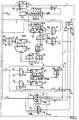
- the system shown in Figure 2 shows the details of the system.
- a portable object (1) composed of its memory (3) and its processing member (4) is introduced through the slot (F) of the device (2).
- the device includes a contact (C x ) to indicate to the latter that a portable object has just been introduced through the slot (F).
- One pad of this contact is connected to the earth of the device, the other is connected to input 1 of the inverter (12) delivering at its output 2 a VAL signal towards input 2 of the sequencer ( 11).
- the input 1 of the sequencer (11) is controlled by the signals delivered by the output 1 of the clock (10).
- the clock (10) can be produced in a very conventional manner using a transistor multivibrator.
- the realization of the sequencer (11) can be done using rockers mounted in rings.
- the sequencer (11) delivers the synchronization signals (T 1 ) to (T 7 ) to the entire system.
- the generator (7) of the random code (E) comprises a counter in rings with n-1 rockers controlled by the output 1 of the clock generator (10).
- the outputs 2 to n of this counter are respectively connected to the parallel inputs 2 to n of a shift register DR (14).
- the register (14) is controlled on its input 1 by the output 1 of the clock generator (10).
- the input DS of the shift register (14) receives the signal (T 3 ) from the sequencer (11) to control the shift in series to the right of the information bits contained in the register (14).
- the input (EP) of the register (14) is connected to the output 4 of the AND gate (15) to control the transfer of the information bits present on the parallel inputs 2 to n in the register.
- the random code (E) leaves the register (14) by its output marked “out and is applied to the inputs 2 of the AND gates (16) and AND (17).
- the AND gates (16) and AND (17) receive on their input 1 the signal VAL delivered by the output 2 of the inverter (12) and on their input 3 the synchronization signal (T 3 ) delivered by the sequencer (11 ).
- the output 4 of the AND gate (16) delivers the signal (E) on the line (1 2 ) when the inputs 1 and 3 are controlled simultaneously by the signals VAL and (T 3 ).
- the output 4 of the AND gate (17) delivers the signal (E) on the line (1 5 ) when the inputs 1 and 3 are controlled simultaneously by the signals VAL and (T 3 ).
- the AND gate (15) is controlled, on its input 1 by the synchronization signal (T 2 ) emitted by the sequencer (11), on its input 2 by the signal VAL emitted by the output of the inverter (12) and on its input 3 by a control signal emitted by the output Q of the rocker (21).
- the rocker (21) is synchronized by the signal coming out of the clock generator (10), its output Q takes the logic state 1 when the input J is controlled and takes the state 0 when its input K is controlled.
- the input J of the rocker (21) is already connected.
- the input K of the rocker (21) is connected to the output 2 of the inverter (22) which receives on its input 1 the signal VAL from the inverter (12).
- the inputs 1 to n-3 of the decoder (20) are respectively connected to the outputs 3 to n of the shift register DR (18).
- the register (18) is synchronized on its input 1 by the signal H emitted by the clock generator (10) and is connected on its input 2 to the output 4 of the AND gate (19) which receives respectively on its inputs 1 , 2 and 3, the signals of the identification code (In) sent on the line (1 1 ), the signal VAL sent by the inverter (12) and the signal (T 1 ) of the sequencer (11).
- the comparison device (8) comprises a comparator (25a) whose inputs 1 to n-2 are respectively connected to outputs 3 to n of the shift register DR (25) and the inputs n-1 to 2n-4 are connected respectively to inputs 3 to n of the shift register DR (26).
- the registers (25) and (26) are synchronized by the synchronization signal H delivered by the clock generator (10) and controlled by the signal VAL emitted by the output 2 of the inverter (12).
- Input 2 of the shift register (25) is connected to output 3 of the AND gate (24) whose inputs 1 and 2 respectively receive the result (R) transmitted by the line (1 3 ) and the synchronization signal (T 5 ).
- the input 2 of the shift register (26) is connected to the output 3 of the AND gate (27) which receives respectively on its inputs 1 and 2 the synchronization signal (T s ) emitted by the sequencer (11) and the result (R ') transmitted on line (1 6 ).
- T s the synchronization signal
- R ' the result transmitted on line (1 6 ).
- the data transfer device (9) includes AND gates (29) and (30).
- the AND gate (29) has 5 inputs, input 1 is controlled by the synchronization signal (T 7 ) sent by the sequencer (11), input 2 receives the signal transmitted on the line (I 8 ), l input 4 receives a control signal (C) emitted by the electronic device (1a), input 3 the signal BC transmitted by output Q of the rocker (28) which takes the logic state 1 when the identity of results (R) is detected by the comparator (25 bis), and on its input 5 the signal VAL emitted by the inverter (12).
- the AND gate (30) also has 5 inputs, input 1 is controlled by the control signal (C) emitted by the electronic device (1a), input 2 receives the signal BC emitted by the rocker (28) , the input 3 is controlled by the synchronization signal (T 7 ) emitted by the sequencer (11), the input 4 receives the data emitted on the line (1 4 ) by the portable object (1), the input 5 is controlled by the signal VAL generated by output 2 of the inverter (12).
- the output 6 of the AND gate (30) transmits the data transmitted on the line (1 4 ) to the line (I 8 ).
- the electronic device (1a) is composed as in FIG. 1 of the memory M6 and the control device (5), it comprises an input-output door (D) to which the lines 5 and 8 are connected and a control output (C) is connected to the transfer doors (9).
- the portable object (1) comprises an entry-exit door (D) to which the lines (1 1 ) to (1 4 ) are connected.
- the operation of the device shown in Figure 2 is as follows.
- the presentation of the portable object in the medium 2 closes the contact (Cx) and brings up the signal VAL at the output of the inverter (12).
- the signal VAL then controls the cycles (T i ) to (T 7 ) of the sequencer (11) under the synchronism of the clock (10).
- the counter (13) is constantly evolving under the synchronism of the clock (10) as soon as the entire system is supplied with electrical energy by a power source not shown.
- the code used for the progression of the counter can be absolutely arbitrary in the case of FIG. 2, the possible combinations are 2n-1 in number.
- the identification code (In) transmitted by the portable object (1) passes through the AND gate (19) and is recorded in the shift register (18) and the decoder (20) identifies the identification code.
- the flip-flop (21) controls the door (15) which in turn controls the transfer of the state of the counter (13) in the shift register DR14 (number E).
- the number (E) contained in the register (14) is transmitted in series by the output "OUT of the register (14) in the direction of a part of the portable object (1) by the line (I 2 ) through the AND gate (16) and on the other hand towards the electronic device (1a) by the line (1 5 ) through the AND gate (17).
- the calculation results are transmitted on the lines (1 3 ) and (1 6 ) in the direction on the one hand of the shift register DR 25 and on the other hand of the shift register DR 26 and the comparison of the results takes place by the comparator (25 bis). If there is equality of results, the flip-flop BC takes state 1 and the transfer of data between the memory 3 of the portable object (1) and the memory (6) of the electronic device (1a) is authorized.
- the person identification system which has just been described is not limited to the exchange of information between the portable object (1) and the device (2).
- the device (2) can be applied to numerous other applications, in particular to accesses to databases of information processing systems, being part of the cash registers of merchants or of cash dispensers.
- the operation of the portable object may be subject to the presentation by its holder of an intangible password, which the latter must present for example on a keyboard. or any other transmission device, to allow its control by the portable object itself.
- the signal BC delivered by the flip-flop (28) can be usefully used for the validation of transactions or operations that the operator holding the portable object wishes to carry out.
Description
- La présente invention concerne un système d'identification de personnes demandant l'accès à certains milieux.
- Il est connu de tels systèmes autorisant des personnes habilitées à accéder à un milieu soit par un mot de passe immatériel, soit par un objet portatif, soit éventuellement les deux. Ces systèmes présentent deux inconvénients majeurs. D'une part pour retirer à une personne son habilitation, il faut informer le milieu. En effet, on ne peut faire oublier à une personne son mot de passe, et elle a pu reproduire ou simuler un objet portatif du type clé ou serrure ou badge. D'autre part un fraudeur peut à l'insu de la personne habilitée, voler le mot de passe, reproduire ou simuler l'objet portatif et ces fraudes ne peuvent pas être diagnostiquées à coup sûr.
- Il est connu par le brevet US-A-3 806 874 un système pour la mise en oeuvre d'un procédé permettant d'identifier des personnes, utilisant d'une part un objet portatif comprenant une mémoire dans laquelle est enregistré un code secret, une mémoire dans laquelle est enregistré un code d'identification, un système de commande à programme, ainsi que des moyens de traitement des informations contenues dans lesdites mémoires et d'autre part un appareil comprenant une mémoire dans laquelle est enregistré un code secret, un système de commande à programme, ainsi que des moyens de traitement des informations contenues dans ladite mémoire, le procédé comportant plusieurs étapes, dont celles consistant à lire le code d'identification enregistré dans la mémoire de l'objet portatif et à générer un code aléatoire à destination des moyens de traitement de l'objet portatif et de l'appareil.
- Ce brevet antérieur ne résoud pas le problème de la fraude possible au niveau de l'appareil, notamment en ce qui concerne le code secret enregistré en permanence dans une mémoire de l'appareil.
- La présente invention consiste à éliminer cet inconvénient grâce à deux objets portatifs à la fois non reproductibles, non simulables et non mémorisables.
- L'invention propose donc un système d'identification de personnes demandant l'accès à un milieu protégé à partir d'un objet portatif comprenant une mémoire dans laquelle sont au moins enregistrés un code secret S, un code d'identification ln du détenteur de l'objet portatif et un programme P, des circuits de traitement pour exécuter le programme P, l'accès audit milieu étant assuré par un appareil auquel ledit objet portatif est connecté, ledit appareil comprenant une mémoire dans laquelle sont au moins enregistrés le même code secret, le même code d'identification ln et le même programme P, des circuits de traitement pour exécuter le programme P, un générateur de nombres aléatoires E et un circuit comparateur pour comparer des résultats R calculés par les circuits de traitement de l'objet portatif et de l'appareil et ainsi autoriser l'accès au milieu en cas d'identité des résultats R, chaque résultat R issu de l'exécution du programme P étant fonction du code secret S, du code d'identification In et d'un nombre aléatoire E émis par le générateur, caractérisé en ce que les circuits de traitement et la mémoire de l'appareil sont situés dans un objet portatif connecté audit appareil, les informations enregistrées dans la mémoire dudit objet portatif étant inaccessibles de l'extérieur.
- L'avantage de ce système est qu'il permet à un milieu d'identifier un objet portatif avec un très haut niveau de sécurité. Le procédé utilisé est le suivant. Le milieu lit dans la mémoire de l'objet portatif le code d'identification ln qui y est inscrit et génère un nombre aléatoire E. Le milieu disposant d'un dispositif électronique similaire à celui de l'objet portatif calcule lui-même la fonction R = p(S, E, In). Ce calcul étant terminé, il propose ensuite le nombre aléatoire E au dispositif électronique de l'objet portatif à identifier puis il contrôle en retour la conformité des résultats obtenus.
- Dans ces conditions, un fraudeur disposant d'un faux objet portatif générant tout de même correctement le code d'identification In est éliminé en raison de tests effectués sur le résultant R qui a nécessité pour son obtention la prise en compte du code secret S.
- A un autre niveau de fraude, une carte légale portant l'identité ln ne peut servir à prouver une autre identité In'.
- L'invention sera mieux comprise à l'aide de la description faite au regard des dessins qui va suivre.
- La figure 1 est une représentation simplifiée du système selon l'invention.
- La figure 2 est une représentation détaillée du système de la figure 1.
- Le système représenté à la figure 1 se compose d'un objet portatif et d'un appareil (2). L'objet portatif (1) comprend au moins une mémoire (3) associée à des moyens de traitement (4). Les moyens de traitement (4) peuvent être constitués d'un microprocesseur comme cela est décrit dans le brevet français N° 2 401 459. L'appareil (2) comprend un dispositif électronique (1 bis) similaire à l'objet portatif (1) composé d'une mémoire (6) et des moyens de traitement (5) de cette mémoire, un générateur (7) de codes aléatoires (E), un comparateur (8) et une porte de transfert (9).
- Dans le cas de la figure 1 le milieu à protéger se trouve être la mémoire (6) pour laquelle l'accès est contrôlé. L'objet portatif (1) peut être relié électriquement au générateur (7) de codes aléatoires (E) par les lignes (11, 10 au comparateur (8) par la liaison (13) et à la porte de transfert (9) par la liaison (14) lorsque l'accès à la mémoire (6) est demandé. Le dispositif électronique (1 bis) est relié au générateur (7) de codes aléatoires (E) par la liaison (15), au comparateur (8) par la liaison (I6) et à la porte de transfert (9) par la liaison (18). La mémoire (3) de l'objet portatif (1) ainsi que celle (6) du dispositif électronique (1 bis) contiennent chacune un code secret (S), un programme P fixe et un code d'identification (In).
- L'accouplement de l'objet portatif (1) aux dispositifs du milieu (2) provoque la lecture du code d'identification (In) dans la mémoire de l'objet portatif (1). Ce code d'identification (In) est déposé sur la ligne (11). Si le code d'identification est plausible, le générateur (7) génère un même code aléatoire (E) sur la ligne (12) à destination de l'objet portatif (1) et sur la ligne (15) à destination du dispositif électronique (1 bis). Les microprocesseurs constituant les moyens de traitement (4) et les moyens de traitement (5) calculent alors chacun un nombre (R) qui est une fonction du code secret (S), du programme (P), du code aléatoire (E) et du code d'identification (In) résidant dans chacune des mémoires.
- Le nombre (R) est transmis sur chacune des liaisons (13) et (I6) à destination du comparateur (8) qui, si la relation entre les deux nombres (R) est acceptable, envoie un signal de commande à la porte de transfert (9) sur la ligne (17), pour autoriser par exemple le transfert des informations entre l'objet portatif (1) et le` dispositif électronique (1 bis) sur les lignes (14) et (I8). La fonction de comparaison des nombres (R) peut être choisie absolument quelconque, dans une réalisation simple le comparateur établira que les deux nombres sont égaux, mais il est bien évident qu'il est possible de choisir une multitude d'autres fonctions logiques. On voit donc qu'un objet portatif (faux) fabriqué par un fraudeur a toutes les chances de générer un faux résultat (R) car ce dernier ne dispose, ni du code secret, ni du programme P.
- D'autre part, on remarquera que la valeur de (E) n'est jamais la même au cours du temps et qu'elle est imprévisible, le résultat du calcul (R) qui correspond à chaque valeur (E) varie donc lui aussi continuement au cours du temps et est également imprévisible ce qui rend inefficace toute tentative de fraude.
- Le système représenté à la figure 2 représente les détails du système. Un objet portatif (1) composé de sa mémoire (3) et de son organe de traitement (4) est introduit par la fente (F) de l'appareil (2). L'appareil comprend un contact (Cx) pour indiquer à celui-ci qu'un objet portatif vient d'être introduit par la fente (F). Un plot de ce contact est relié à la masse de l'appareil, l'autre est relié à l'entrée 1 de l'inverseur (12) délivrant à sa sortie 2 un signal VAL en direction de l'entrée 2 du séquenceur (11). L'entrée 1 du séquenceur (11) est pilotée par les signaux délivrés par la sortie 1 de l'horloge (10). L'horloge (10) peut être réalisée de façon très classique à l'aide d'un multivibrateur à transistors. La réalisation du séquenceur (11) pourra être faite à l'aide de basculeurs montés en anneaux. Le séquenceur (11) délivre les signaux de synchronisation (T1) à (T7) à l'ensemble du système.
- Le générateur (7) du code aléatoire (E) comprend un compteur en anneaux à n-1 basculeurs piloté par la sortie 1 du générateur d'horloge (10). Les sorties 2 à n de ce compteur sont reliées respectivement aux entrées parallèles 2 à n d'un registre à décalage DR (14). Le registre (14) est piloté sur son entrée 1 par la sortie 1 du générateur d'horloge (10). L'entrée DS du registre à décalage (14) reçoit le signal (T3) du séquenceur (11) pour commander le décalage en série vers la droite des bits d'information contenus dans le registre (14). L'entrée (EP) du registre (14) est reliée à la sortie 4 de la porte ET (15) pour commander le transfert des bits d'informations présents sur les entrées parallèles 2 à n dans le registre. Le code aléatoire (E) sort du registre (14) par sa sortie marquée « out et est appliqué sur les entrées 2 des portes ET (16) et ET (17). Les portes ET (16) et ET (17) reçoivent sur leur entrée 1 le signal VAL délivré par la sortie 2 de l'inverseur (12) et sur leur entrée 3 le signal de synchronisation (T3) délivré par le séquenceur (11). La sortie 4 de la porte ET (16) délivre le signal (E) sur la ligne (12) lorsque les entrées 1 et 3 sont commandées simultanément par les signaux VAL et (T3).
- La sortie 4 de la porte ET (17) délivre le signal (E) sur la ligne (15) lorsque les entrées 1 et 3 sont commandées simultanément par les signaux VAL et (T3). La porte ET (15) est commandée, sur son entrée 1 par le signal de synchronisation (T2) émis par le séquenceur (11), sur son entrée 2 par le signal VAL émis par la sortie de l'inverseur (12) et sur son entrée 3 par un signal de commande émis par la sortie Q du basculeur (21). Le basculeur (21) est synchronisé par le signal sortant du générateur d'horloge (10), sa sortie Q prend l'état 1 logique lorsque l'entrée J est commandée et prend l'état 0 lorsque son entrée K est commandée. L'entrée J du basculeur (21) est reliée àja. sortie 4 de la porte ET (23) qui reçoit respectivement sur ses entrées 1, 2 et 3, un signal émis par la sortie n-2 du décodeur (20), le signal VAL de l'inverseur (12) et le signal de synchronisation (T2) délivré par le séquenceur (11).
- L'entrée K du basculeur (21) est reliée à la sortie 2 de l'inverseur (22) qui reçoit sur son entrée 1 le signal VAL de l'inverseur (12). Les entrées 1 à n-3 du décodeur (20) sont reliées respectivement aux sorties 3 à n du registre à décalage DR (18). Le registre (18) est synchronisé sur son entrée 1 par le signal H émis par le générateur d'horloge (10) et est connecté sur son entrée 2 à la sortie 4 de la porte ET (19) qui reçoit respectivement sur ses entrées 1, 2 et 3, les signaux du code d'identification (In) émis sur la ligne (11), le signal VAL émis par l'inverseur (12) et le signal (T1) du séquenceur (11).
- Le dispositif de comparaison (8), comprend un comparateur (25 bis) dont les entrées 1 à n-2 sont reliées respectivement aux sorties 3 à n du registre à décalage DR (25) et les entrées n-1 à 2n-4 sont reliées respectivement aux entrées 3 à n du registre à décalage DR (26). Les registres (25) et (26) sont synchronisés par le signal de synchronisation H délivré par le générateur d'horloge (10) et commandés par le signal VAL émis par la sortie 2 de l'inverseur (12). L'entrée 2 du registre à décalage (25) est reliée à la sortie 3 de la porte ET (24) dont les entrées 1 et 2 reçoivent respectivement le résultat (R) transmis par la ligne (13) et le signal de synchronisation (T5). L'entrée 2 du registre à décalage (26) est reliée à la sortie 3 de la porte ET (27) qui reçoit respectivement sur ses entrées 1 et 2 le signal de synchronisation (Ts) émis par le séquenceur (11) et le résultat (R') transmis sur la ligne (16). Lorsqu'il y a identité entre les contenus des registres (25) et (26) un signal apparaît sur la sortie 2 du comparateur (25 bis), ce signal est transmis sur l'entrée 1 du basculeur (28) synchronisé par le signal d'horloge émis par le générateur (10). Le basculeur (28) est remis à zéro par le signal VAL généré par la sortie de l'inverseur (12) et appliqué sur l'entrée (R) du basculeur (28).
- Le dispositif de transfert de données (9) comprend les portes ET (29) et (30). La porte ET (29) a 5 entrées, l'entrée 1 est commandée par le signal de synchronisation (T7) émis par le séquenceur (11), l'entrée 2 reçoit le signal transmis sur la ligne (I8), l'entrée 4 reçoit un signal de commande (C) émis par le dispositif électronique (1 bis), l'entrée 3 le signal BC transmis par la sortie Q du basculeur (28) qui prend l'état 1 logique lorsque l'identité des résultats (R) est détectée par le comparateur (25 bis), et sur son entrée 5 le signal VAL émis par l'inverseur (12). La porte ET (30) a également 5 entrées, l'entrée 1 est commandée par le signal de commande (C) émis par le dispositif électronique (1 bis), l'entrée 2 reçoit le signal BC émis par le basculeur (28), l'entrée 3 est commandée par le signal de synchronisation (T7) émis par le séquenceur (11), l'entrée 4 reçoit les données émises sur la ligne (14) par l'objet portatif (1), l'entrée 5 est commandée par le signal VAL généré par la sortie 2 de l'inverseur (12). La sortie 6 de la porte ET (30) transmet les données transmises sur la ligne (14) vers la ligne (I8). Le dispositif électronique (1 bis) se compose comme sur la figure 1 de la mémoire M6 et du dispositif de commande (5), il comprend une porte d'entrée-sortie (D) sur laquelle viennent se raccorder les lignes 5 et 8 et une sortie de commande (C) est reliée aux portes de transfert (9).
- De même l'objet portatif (1) comprend une porte d'entrée-sortie (D) sur laquelle viennent se raccorder les lignes (11) à (14).
- Le fonctionnement du dispositif représenté à la figure 2 est le suivant. La présentation de l'objet portatif dans le milieu 2 ferme le contact (Cx) et fait apparaître le signal VAL à la sortie de l'inverseur (12). Le signal VAL commande alors les cycles (Ti) à (T7) du séquenceur (11) sous le synchronisme de l'horloge (10). Le compteur (13) évolue en permanence sous le synchronisme de l'horloge (10) dès que l'ensemble du système est alimenté en énergie électrique par une source d'alimentation non représentée. Le code utilisé pour la progression du compteur peut être absolument quelconque dans le cas de figure 2, les combinaisons possibles sont au nombre de 2n-1. A l'instant (T1) le code d'identification (In) émis par l'objet portatif (1) traverse la porte ET (19) et s'enregistre dans le registre à décalage (18) et le décodeur (20) identifie le code d'identification. A l'instant (T2), si le code d'identification est correct, la bascule (21) commande la porte (15) qui commande à son tour le transfert de l'état du compteur (13) dans le registre à décalage DR14 (nombre E). A l'instant (T3), le nombre (E) contenu dans le registre (14) est transmis en série par la sortie « OUT du registre (14) en direction d'une part de l'objet portatif (1) par la ligne (I2) au travers de la porte ET (16) et d'autre part en direction du dispositif électronique (1 bis) par la ligne (15) au travers de la porte ET (17). Les microprocesseurs contenus dans l'objet portatif (1) et dans le dispositif (1 bis) calculent alors le nombre R = p(S, E, In) pendant l'instant (T4). A l'instant (Ts), les résultats de calcul sont transmis sur les lignes (13) et (16) en direction d'une part du registre à décalage DR25 et d'autre part du registre à décalage DR26 et la comparaison des résultats a lieu par le comparateur (25 bis). S'il y a égalité des résultats, la bascule BC prend l'état 1 et le transfert des données entre la mémoire 3 de l'objet portatif (1) et la mémoire (6) du dispositif électronique (1 bis) est autorisée.
- Le système d'identification de personnes qui vient d'être décrit n'est pas limité à l'échange d'informations entre l'objet portatif (1) et l'appareil (2). L'appareil (2) pourra être appliqué à de nombreuses autres applications notamment aux accès de banques de données des systèmes de traitement de l'information, faire partie des caisses enregistreuses des commerçants ou des distributeurs de billets de banque.
- Dans certains de ces cas et sans sortir du cadre même de l'invention, on pourra soumettre le fonctionnement de l'objet portatif à la présentation par son titulaire d'un mot de passe immatériel, que ce dernier devra présenter par exemple sur un clavier ou tout autre dispositif de transmission, pour permettre son contrôle par l'objet portatif lui-même.
- Dans tous ces cas, le signal BC délivré par la bascule (28) pourra être utilement utilisé à la validation des transactions ou des opérations que l'opérateur titulaire de l'objet portatif désirera effectuer.
Claims (1)
- Système d'identification de personnes demandant l'accès à un milieu protégé à partir d'un objet portatif (1) comprenant une mémoire (3) dans laquelle sont au moins enregistrés un code secret (S), un code d'identification (In) du détenteur de l'objet portatif (1) et un programme (P), des circuits de traitement (4) pour exécuter le programme (P), l'accès audit milieu étant assuré par un appareil (2) auquel ledit objet portatif (1) est connecté, ledit appareil (2) comprenant une mémoire (6) dans laquelle sont au moins enregistrés le même code secret (S), le même code d'identification (In) et le même programme (P), des circuits de traitement (5) pour exécuter le programme (P), un générateur (7) de nombres aléatoires (E) et un circuit comparateur (8) pour comparer des résultats (R) calculés par les circuits de traitement (4 ; 5) de l'objet portatif (1) et de l'appareil (2) et ainsi autoriser l'accès au milieu en cas d'identité des résultats (R), chaque résultat (R) issu de l'exécution du programme (P) étant fonction du code secret (S), du code d'identification (In) et d'un nombre aléatoire (E) émis par le générateur (7), caractérisé en ce que les circuits de traitement (5) et la mémoire (6) de l'appareil (2) sont situés dans un objet portatif (1 bis) connecté audit appareil (2), les informations enregistrées dans la mémoire (6) de l'objet portatif (1 bis) étant inaccessibles de l'extérieur.
Applications Claiming Priority (2)
| Application Number | Priority Date | Filing Date | Title |
|---|---|---|---|
| FR7927705 | 1979-11-09 | ||
| FR7927705A FR2469760A1 (fr) | 1979-11-09 | 1979-11-09 | Procede et systeme d'identification de personnes demandant l'acces a certains milieux |
Publications (2)
| Publication Number | Publication Date |
|---|---|
| EP0028965A1 EP0028965A1 (fr) | 1981-05-20 |
| EP0028965B1 true EP0028965B1 (fr) | 1984-06-13 |
Family
ID=9231507
Family Applications (1)
| Application Number | Title | Priority Date | Filing Date |
|---|---|---|---|
| EP80401534A Expired EP0028965B1 (fr) | 1979-11-09 | 1980-10-29 | Système d'identification de personnes demandant l'accès à certains milieux |
Country Status (4)
| Country | Link |
|---|---|
| US (1) | US4471216A (fr) |
| EP (1) | EP0028965B1 (fr) |
| DE (1) | DE3068240D1 (fr) |
| FR (1) | FR2469760A1 (fr) |
Cited By (1)
| Publication number | Priority date | Publication date | Assignee | Title |
|---|---|---|---|---|
| USRE38419E1 (en) | 1986-05-13 | 2004-02-10 | Ncr Corporation | Computer interface device |
Families Citing this family (148)
| Publication number | Priority date | Publication date | Assignee | Title |
|---|---|---|---|---|
| FR2483713A1 (fr) * | 1980-05-30 | 1981-12-04 | Cii Honeywell Bull | Dispositif pour la transmission de signaux entre deux stations de traitement de l'information |
| GB2092344B (en) * | 1981-01-30 | 1985-12-18 | Halpern John Wolfgang | Security in electronic fund transfer systems |
| SE426128B (sv) * | 1981-04-08 | 1982-12-06 | Philips Svenska Ab | Metod vid overforing av datameddelanden mellan tva stationer, samt overforingsanleggning for utforande av metoden |
| IT1139526B (it) * | 1981-10-13 | 1986-09-24 | Antonio Invernizzi | Serratura e relativa chiave di tipo elettronico |
| NL8201077A (nl) * | 1982-03-16 | 1983-10-17 | Philips Nv | Kommunikatiesysteem, bevattende een centrale dataverwerkende inrichting, toegangsstations en externe stations, waarbij een kryptografische kontrole is voorzien op vervalsing van een extern station, alsmede externe stations voor gebruik in zo een kommunikatiesysteem. |
| GB2120434B (en) * | 1982-04-22 | 1986-03-12 | Enigma Logic Inc | A security system |
| FR2526977B1 (fr) * | 1982-05-14 | 1988-06-10 | Cii Honeywell Bull | Procede et dispositif pour authentifier ou certifier au moins une information contenue dans une memoire d'un support electronique notamment amovible et portatif tel qu'une carte |
| FR2530053B1 (fr) * | 1982-07-08 | 1986-04-25 | Bull Sa | Procede pour certifier la provenance d'au moins une information enregistree dans une memoire d'un premier dispositif electronique et transmise a un deuxieme dispositif electronique, et systeme pour la mise en oeuvre d'un tel procede |
| DE3225754A1 (de) * | 1982-07-09 | 1984-01-12 | Hülsbeck & Fürst GmbH & Co KG, 5620 Velbert | Verfahren zur schliesswirksamen wechselwirkung eines schluesselartigen teils mit einem schlossartigen teil |
| US4757468A (en) * | 1982-09-22 | 1988-07-12 | Intel Corporation | Authenticated read-only memory |
| FR2536880B1 (fr) * | 1982-11-30 | 1987-05-07 | Bull Sa | Microprocesseur concu notamment pour executer les algorithmes de calcul d'un systeme de chiffrement a cle publique |
| EP0112944B1 (fr) * | 1982-12-30 | 1987-03-04 | International Business Machines Corporation | Examen de la validité de codes d'identification |
| FR2539897B1 (fr) * | 1983-01-20 | 1988-12-30 | Cii Honeywell Bull | Procede et dispositif pour habiliter le detenteur d'un objet portatif tel qu'une carte, a acceder par cette carte a au moins un service dispense par au moins un organisme habilitant |
| US4906828A (en) * | 1983-02-28 | 1990-03-06 | Paperless Accounting, Inc. | Electronic money purse and fund transfer system |
| FR2549989B1 (fr) * | 1983-07-29 | 1985-09-13 | Philips Ind Commerciale | Systeme d'authentification entre un lecteur de carte et une carte de paiement echangeant des informations |
| GB2146814A (en) * | 1983-09-17 | 1985-04-24 | Ibm | Electronic fund transfer systems |
| GB2146815A (en) * | 1983-09-17 | 1985-04-24 | Ibm | Electronic fund transfer systems |
| EP0137995B1 (fr) * | 1983-10-14 | 1990-10-17 | Kabushiki Kaisha Toshiba | Micro-ordinateur monopuce ayant une fonction chiffrable de sa mémoire de programmes |
| US4799258A (en) * | 1984-02-13 | 1989-01-17 | National Research Development Corporation | Apparatus and methods for granting access to computers |
| US4630201A (en) * | 1984-02-14 | 1986-12-16 | International Security Note & Computer Corporation | On-line and off-line transaction security system using a code generated from a transaction parameter and a random number |
| US4599489A (en) * | 1984-02-22 | 1986-07-08 | Gordian Systems, Inc. | Solid state key for controlling access to computer software |
| JPS60176186A (ja) * | 1984-02-23 | 1985-09-10 | Omron Tateisi Electronics Co | Icカ−ドシステム |
| DE3410937A1 (de) * | 1984-03-24 | 1985-10-03 | Philips Patentverwaltung Gmbh, 2000 Hamburg | Verfahren zum erkennen der unerlaubten benutzung einer indentifizierung |
| US4709137A (en) * | 1984-04-16 | 1987-11-24 | Omron Tateisi Electronics Co. | IC card and financial transaction processing system using IC card |
| DE3417766A1 (de) * | 1984-05-12 | 1985-11-14 | Betriebswirtschaftliches Institut der Deutschen Kreditgenossenschaften BIK GmbH, 6000 Frankfurt | Arbeits-verfahren und einrichtung zum elektronisch autorisierten feststellen einer sache |
| US4652698A (en) * | 1984-08-13 | 1987-03-24 | Ncr Corporation | Method and system for providing system security in a remote terminal environment |
| US4694492A (en) * | 1984-11-09 | 1987-09-15 | Pirmasafe, Inc. | Computer communications security control system |
| US4691355A (en) * | 1984-11-09 | 1987-09-01 | Pirmasafe, Inc. | Interactive security control system for computer communications and the like |
| US4720860A (en) * | 1984-11-30 | 1988-01-19 | Security Dynamics Technologies, Inc. | Method and apparatus for positively identifying an individual |
| US5168520A (en) * | 1984-11-30 | 1992-12-01 | Security Dynamics Technologies, Inc. | Method and apparatus for personal identification |
| US5367572A (en) * | 1984-11-30 | 1994-11-22 | Weiss Kenneth P | Method and apparatus for personal identification |
| US4998279A (en) * | 1984-11-30 | 1991-03-05 | Weiss Kenneth P | Method and apparatus for personal verification utilizing nonpredictable codes and biocharacteristics |
| US4679236A (en) * | 1984-12-21 | 1987-07-07 | Davies Richard E | Identification verification method and system |
| US4736419A (en) * | 1984-12-24 | 1988-04-05 | American Telephone And Telegraph Company, At&T Bell Laboratories | Electronic lock system |
| US4800590A (en) * | 1985-01-14 | 1989-01-24 | Willis E. Higgins | Computer key and computer lock system |
| US4783798A (en) * | 1985-03-14 | 1988-11-08 | Acs Communications Systems, Inc. | Encrypting transponder |
| CH668134A5 (de) * | 1985-03-15 | 1988-11-30 | Hasler Ag Ascom | Vorrichtung und verfahren zum freigeben und kontrollierten einspeichern beliebiger vorgabebetraege in den vorgabespeicher einer frankiermaschine. |
| JPH0632099B2 (ja) * | 1985-05-15 | 1994-04-27 | 日本電気株式会社 | カ−ド書込装置 |
| FR2583186B1 (fr) * | 1985-06-07 | 1987-10-02 | Flonic Sa | Systeme de gestion de stationnement payant |
| JPS61296433A (ja) * | 1985-06-24 | 1986-12-27 | Nintendo Co Ltd | 外部記憶装置のソフトウエア管理システム |
| CA1270339A (fr) * | 1985-06-24 | 1990-06-12 | Katsuya Nakagawa | Dispositif pour determiner l'exactitude d'un logiciel dans un appareil de traitement de donnees |
| JPH0760412B2 (ja) * | 1985-06-28 | 1995-06-28 | 任天堂株式会社 | 真偽判別素子、およびそれを用いた外部記憶装置 |
| DE3529882A1 (de) * | 1985-08-21 | 1987-02-26 | Vdo Schindling | System zum ver- und / oder entriegeln einer sicherheitseinrichtung |
| USRE34161E (en) * | 1985-10-04 | 1993-01-12 | Nintendo Company Limited | Memory cartridge and information processor unit using such cartridge |
| JPH074449B2 (ja) * | 1985-10-04 | 1995-01-25 | 任天堂株式会社 | ゲ−ム機用カ−トリツジとそれを用いるゲ−ム機 |
| US4799061A (en) * | 1985-11-18 | 1989-01-17 | International Business Machines Corporation | Secure component authentication system |
| FR2592197A1 (fr) * | 1985-12-19 | 1987-06-26 | Nixon John | Procede d'identification d'une personne, notamment d'un demandeur d'un service tel que par exemple d'une transaction bancaire, a l'aide d'une piece d'identification, dispositif de mise en oeuvre du procede, des pieces d'identification utilisables pour le procede precite et procede pour la realisation de telles pieces |
| JPS62147586A (ja) * | 1985-12-23 | 1987-07-01 | Hitachi Ltd | 不正防止方式 |
| FR2592510B1 (fr) * | 1985-12-31 | 1988-02-12 | Bull Cp8 | Procede et appareil pour certifier des services obtenus a l'aide d'un support portatif tel qu'une carte a memoire |
| WO1987005420A1 (fr) * | 1986-03-10 | 1987-09-11 | Data Card Corporation | Dispositif a carte intelligente et procede de programmation |
| US4874935A (en) * | 1986-03-10 | 1989-10-17 | Data Card Coprporation | Smart card apparatus and method of programming same |
| FR2597538B1 (fr) * | 1986-04-22 | 1995-03-31 | Soum Rene | Ensemble cle-serrure de securite a telecommande dans lequel la cle n'a qu'une fonction d'emission et la serrure de reception |
| US4742215A (en) * | 1986-05-07 | 1988-05-03 | Personal Computer Card Corporation | IC card system |
| US4731841A (en) * | 1986-06-16 | 1988-03-15 | Applied Information Technologies Research Center | Field initialized authentication system for protective security of electronic information networks |
| FR2600189B1 (fr) * | 1986-06-16 | 1991-02-01 | Bull Cp8 | Procede pour faire authentifier par un milieu exterieur un objet portatif tel qu'une carte a memoire accouplee a ce milieu |
| FR2601476B1 (fr) * | 1986-07-11 | 1988-10-21 | Bull Cp8 | Procede pour authentifier une donnee d'habilitation externe par un objet portatif tel qu'une carte a memoire |
| FR2601535B1 (fr) * | 1986-07-11 | 1988-10-21 | Bull Cp8 | Procede pour certifier l'authenticite d'une donnee echangee entre deux dispositifs connectes en local ou a distance par une ligne de transmission |
| ATE116778T1 (de) * | 1986-09-02 | 1995-01-15 | Pitney Bowes Inc | Automatisches überweisungssystem mit mikroprozessorkarten. |
| US4759062A (en) * | 1986-10-06 | 1988-07-19 | International Electronics Technology Corporation | Arrangement for and method of protecting private security codes from unauthorized disclosure |
| US5109413A (en) * | 1986-11-05 | 1992-04-28 | International Business Machines Corporation | Manipulating rights-to-execute in connection with a software copy protection mechanism |
| US4916738A (en) * | 1986-11-05 | 1990-04-10 | International Business Machines Corp. | Remote access terminal security |
| US4817140A (en) * | 1986-11-05 | 1989-03-28 | International Business Machines Corp. | Software protection system using a single-key cryptosystem, a hardware-based authorization system and a secure coprocessor |
| US5148534A (en) * | 1986-11-05 | 1992-09-15 | International Business Machines Corp. | Hardware cartridge representing verifiable, use-once authorization |
| US4969188A (en) * | 1987-02-17 | 1990-11-06 | Gretag Aktiengesellschaft | Process and apparatus for the protection of secret elements in a network of encrypting devices with open key management |
| FR2613565B1 (fr) * | 1987-04-03 | 1989-06-23 | Bull Cps | Procede pour acheminer des cles secretes vers des modules de securite et des cartes utilisateurs, dans un reseau de traitement d'informations |
| FR2615638B1 (fr) * | 1987-05-20 | 1989-07-21 | Dassault Electronique | Dispositif et procede d'habilitation informatique ou telematique |
| GB2205186B (en) * | 1987-05-23 | 1991-02-13 | Motorola Inc | Memory cards |
| FR2618002B1 (fr) * | 1987-07-10 | 1991-07-05 | Schlumberger Ind Sa | Procede et systeme d'authentification de cartes a memoire electronique |
| US4827518A (en) * | 1987-08-06 | 1989-05-02 | Bell Communications Research, Inc. | Speaker verification system using integrated circuit cards |
| US4944008A (en) * | 1988-02-18 | 1990-07-24 | Motorola, Inc. | Electronic keying scheme for locking data |
| US4941174A (en) * | 1988-04-19 | 1990-07-10 | General Electric Company | Digital radio with security system for selectively enabling software controlled options |
| CH675920A5 (en) * | 1988-05-20 | 1990-11-15 | Gretag Ag | Access control using smart card - using code data generated to provide access to secured units |
| GB2260208B (en) * | 1989-02-18 | 1993-09-01 | Olivetti Res Ltd | Authentication system |
| GB2230365B (en) * | 1989-02-18 | 1993-05-26 | Olivetti Research Ltd | Mobile carrier tracking system |
| FR2654234A1 (fr) * | 1989-11-03 | 1991-05-10 | Gremillet Dominique | Dispositif et procede pour la realisation de verrouillages materiels ou logiciels, dynamiques et aleatoires, associes a des clefs dynamiques et intelligentes. |
| US5120939A (en) * | 1989-11-09 | 1992-06-09 | At&T Bell Laboratories | Databaseless security system |
| US5130519A (en) * | 1990-01-16 | 1992-07-14 | George Bush | Portable pin card |
| KR0146067B1 (ko) * | 1990-03-09 | 1998-09-15 | 문정환 | 롬 데이타 보호방법 및 장치 |
| GB2242769B (en) * | 1990-04-02 | 1994-02-09 | Brandsystem Ltd | Card security systems |
| FR2667715A1 (fr) * | 1990-10-09 | 1992-04-10 | Gemplus Card Int | Procede et dispositif pour accroitre la protection d'une carte a memoire. |
| US5196840A (en) * | 1990-11-05 | 1993-03-23 | International Business Machines Corporation | Secure communications system for remotely located computers |
| NO300045B1 (no) * | 1990-12-03 | 1997-03-24 | Trioving As | Tidskontrollert elektrisk styrt låssystem |
| US5237614A (en) * | 1991-06-07 | 1993-08-17 | Security Dynamics Technologies, Inc. | Integrated network security system |
| US5193114A (en) * | 1991-08-08 | 1993-03-09 | Moseley Donald R | Consumer oriented smart card system and authentication techniques |
| US5177789A (en) * | 1991-10-09 | 1993-01-05 | Digital Equipment Corporation | Pocket-sized computer access security device |
| US5357604A (en) * | 1992-01-30 | 1994-10-18 | A/N, Inc. | Graphics processor with enhanced memory control circuitry for use in a video game system or the like |
| US5388841A (en) * | 1992-01-30 | 1995-02-14 | A/N Inc. | External memory system having programmable graphics processor for use in a video game system or the like |
| CA2074388C (fr) * | 1992-01-30 | 2003-01-14 | Jeremy E. San | Processeur graphique programmable a logiciel de conversion de pixels en caracteres pour jeux video ou systemes similaires |
| US5310999A (en) * | 1992-07-02 | 1994-05-10 | At&T Bell Laboratories | Secure toll collection system for moving vehicles |
| EP0579099B1 (fr) * | 1992-07-08 | 1997-01-02 | Daifuku Co., Ltd. | Conteneur pour objets en forme de disques |
| US5361062A (en) * | 1992-11-25 | 1994-11-01 | Security Dynamics Technologies, Inc. | Personal security system |
| FR2716280B1 (fr) * | 1994-02-11 | 1996-04-12 | Solaic Sa | Procédé de protection des composants de cartes à mémoire contre des utilisations frauduleuses. |
| US5539828A (en) * | 1994-05-31 | 1996-07-23 | Intel Corporation | Apparatus and method for providing secured communications |
| US5892900A (en) | 1996-08-30 | 1999-04-06 | Intertrust Technologies Corp. | Systems and methods for secure transaction management and electronic rights protection |
| US6658568B1 (en) | 1995-02-13 | 2003-12-02 | Intertrust Technologies Corporation | Trusted infrastructure support system, methods and techniques for secure electronic commerce transaction and rights management |
| US7124302B2 (en) | 1995-02-13 | 2006-10-17 | Intertrust Technologies Corp. | Systems and methods for secure transaction management and electronic rights protection |
| US6157721A (en) | 1996-08-12 | 2000-12-05 | Intertrust Technologies Corp. | Systems and methods using cryptography to protect secure computing environments |
| US7095854B1 (en) | 1995-02-13 | 2006-08-22 | Intertrust Technologies Corp. | Systems and methods for secure transaction management and electronic rights protection |
| US7143290B1 (en) | 1995-02-13 | 2006-11-28 | Intertrust Technologies Corporation | Trusted and secure techniques, systems and methods for item delivery and execution |
| US7133846B1 (en) | 1995-02-13 | 2006-11-07 | Intertrust Technologies Corp. | Digital certificate support system, methods and techniques for secure electronic commerce transaction and rights management |
| US5943422A (en) | 1996-08-12 | 1999-08-24 | Intertrust Technologies Corp. | Steganographic techniques for securely delivering electronic digital rights management control information over insecure communication channels |
| US6948070B1 (en) | 1995-02-13 | 2005-09-20 | Intertrust Technologies Corporation | Systems and methods for secure transaction management and electronic rights protection |
| US7165174B1 (en) | 1995-02-13 | 2007-01-16 | Intertrust Technologies Corp. | Trusted infrastructure support systems, methods and techniques for secure electronic commerce transaction and rights management |
| US7133845B1 (en) | 1995-02-13 | 2006-11-07 | Intertrust Technologies Corp. | System and methods for secure transaction management and electronic rights protection |
| US7069451B1 (en) | 1995-02-13 | 2006-06-27 | Intertrust Technologies Corp. | Systems and methods for secure transaction management and electronic rights protection |
| DE69638018D1 (de) | 1995-02-13 | 2009-10-15 | Intertrust Tech Corp | Systeme und Verfahren zur Verwaltung von gesicherten Transaktionen und zum Schutz von elektronischen Rechten |
| NL1000352C2 (nl) * | 1995-05-12 | 1996-11-13 | Nederland Ptt | Elektronisch betaalsysteem met verschillende rekeneenheden, elektronisch betaalmiddel alsmede werkwijze voor elektronisch betalen. |
| FR2739737B1 (fr) * | 1995-10-09 | 1997-11-21 | Inside Technologies | Perfectionnements aux cartes a memoire |
| US6071191A (en) * | 1995-11-22 | 2000-06-06 | Nintendo Co., Ltd. | Systems and methods for providing security in a video game system |
| US6190257B1 (en) | 1995-11-22 | 2001-02-20 | Nintendo Co., Ltd. | Systems and method for providing security in a video game system |
| GB9523922D0 (en) * | 1995-11-23 | 1996-01-24 | At & T Global Inf Solution | Method of authenticating an application program and a system therefor |
| US5949881A (en) * | 1995-12-04 | 1999-09-07 | Intel Corporation | Apparatus and method for cryptographic companion imprinting |
| US6097292A (en) * | 1997-04-01 | 2000-08-01 | Cubic Corporation | Contactless proximity automated data collection system and method |
| US6075861A (en) * | 1996-05-29 | 2000-06-13 | At&T Corp. | Security access system |
| US6463416B1 (en) * | 1996-07-15 | 2002-10-08 | Intelli-Check, Inc. | Authentication system for identification documents |
| FR2753556B1 (fr) * | 1996-09-13 | 1998-11-13 | Schlumberger Ind Sa | Methode d'authentification de cartes |
| US5828753A (en) | 1996-10-25 | 1998-10-27 | Intel Corporation | Circuit and method for ensuring interconnect security within a multi-chip integrated circuit package |
| US20050021477A1 (en) * | 1997-01-29 | 2005-01-27 | Ganapathy Krishnan | Method and system for securely incorporating electronic information into an online purchasing application |
| US7062500B1 (en) | 1997-02-25 | 2006-06-13 | Intertrust Technologies Corp. | Techniques for defining, using and manipulating rights management data structures |
| US6247129B1 (en) | 1997-03-12 | 2001-06-12 | Visa International Service Association | Secure electronic commerce employing integrated circuit cards |
| JPH1153317A (ja) * | 1997-08-07 | 1999-02-26 | Nec Corp | パスワード入力装置 |
| US6128391A (en) * | 1997-09-22 | 2000-10-03 | Visa International Service Association | Method and apparatus for asymetric key management in a cryptographic system |
| US7092914B1 (en) | 1997-11-06 | 2006-08-15 | Intertrust Technologies Corporation | Methods for matching, selecting, narrowcasting, and/or classifying based on rights management and/or other information |
| US6128738A (en) * | 1998-04-22 | 2000-10-03 | International Business Machines Corporation | Certificate based security in SNA data flows |
| US6266525B1 (en) * | 1998-12-17 | 2001-07-24 | Lucent Technologies Inc. | Method for detecting fraudulent use of a communications system |
| US6985583B1 (en) * | 1999-05-04 | 2006-01-10 | Rsa Security Inc. | System and method for authentication seed distribution |
| DE19926472C2 (de) | 1999-06-10 | 2001-11-15 | Call A Bike Mobilitaetssysteme | Verfahren zum Übermitteln eines Codes |
| US7430670B1 (en) | 1999-07-29 | 2008-09-30 | Intertrust Technologies Corp. | Software self-defense systems and methods |
| NL1014274C2 (nl) * | 2000-02-03 | 2001-08-16 | Tele Atlas Bv | Stelsel voor het beveiligen van op een datadrager aanwezige data. |
| US20010054147A1 (en) * | 2000-04-04 | 2001-12-20 | Richards Ernest S. | Electronic identifier |
| US7430537B2 (en) | 2000-07-10 | 2008-09-30 | Paypal, Inc. | System and method for verifying a financial instrument |
| US6986057B1 (en) * | 2000-08-07 | 2006-01-10 | Dallas Semiconductor Corporation | Security device and method |
| JP2003157332A (ja) * | 2001-11-21 | 2003-05-30 | Oki Electric Ind Co Ltd | 本人確認装置、本人確認システム、カード発行装置及びカード発行システム |
| US7363494B2 (en) * | 2001-12-04 | 2008-04-22 | Rsa Security Inc. | Method and apparatus for performing enhanced time-based authentication |
| US7708189B1 (en) | 2002-05-17 | 2010-05-04 | Cipriano Joseph J | Identification verification system and method |
| CN1405718A (zh) * | 2002-07-19 | 2003-03-26 | 叶昇武 | 一种用户身份识别防盗系统及识别方法 |
| US7725712B2 (en) * | 2003-10-14 | 2010-05-25 | Syferlock Technology Corporation | User authentication system and method |
| AU2004282865B2 (en) | 2003-10-14 | 2009-05-28 | Syferlock Technology Corporation | Authentication system |
| US20050224313A1 (en) * | 2004-01-26 | 2005-10-13 | Cubic Corporation | Robust noncontact media processor |
| JP2005318528A (ja) * | 2004-03-29 | 2005-11-10 | Sanyo Electric Co Ltd | 無線伝送装置、相互認証方法および相互認証プログラム |
| US7860318B2 (en) | 2004-11-09 | 2010-12-28 | Intelli-Check, Inc | System and method for comparing documents |
| CN101120351B (zh) * | 2005-02-18 | 2010-10-06 | Rsa安全公司 | 派生种子的分发方法 |
| US7792522B1 (en) | 2006-01-13 | 2010-09-07 | Positive Access Corporation | Software key control for mobile devices |
| US7810134B2 (en) | 2007-01-22 | 2010-10-05 | First Data Corporation | Authentication system for financial transactions |
| US20150134302A1 (en) | 2013-11-14 | 2015-05-14 | Jatin Chhugani | 3-dimensional digital garment creation from planar garment photographs |
| US10366439B2 (en) | 2013-12-27 | 2019-07-30 | Ebay Inc. | Regional item reccomendations |
| US20160092956A1 (en) | 2014-09-30 | 2016-03-31 | Jonathan Su | Garment size mapping |
| US10373409B2 (en) | 2014-10-31 | 2019-08-06 | Intellicheck, Inc. | Identification scan in compliance with jurisdictional or other rules |
Family Cites Families (11)
| Publication number | Priority date | Publication date | Assignee | Title |
|---|---|---|---|---|
| NL6906145A (fr) * | 1968-05-15 | 1969-11-18 | ||
| GB1285445A (en) * | 1968-08-30 | 1972-08-16 | Smiths Industries Ltd | Improvements in or relating to access-control equipment and item-dispensing systems including such equipment |
| US3764742A (en) * | 1971-12-23 | 1973-10-09 | Ibm | Cryptographic identification system |
| SE381940B (sv) * | 1972-04-11 | 1975-12-22 | Gretag Ag | Anordning for enskild identifiering av ett flertal individer |
| DE2635180C3 (de) * | 1976-08-05 | 1981-03-19 | Wächtler, Maximilian, Dr., 2409 Sierksdorf, Post Haffkrug | Verfahren zur elektronisch gesteuerten Freigabe von Tür-, Safe- und Funktionsschlössern unter Verwendung elektronisch codierter Schlüssel sowie Schaltungsanordnung zur Durchführung des Verfahrens |
| FR2417141A1 (fr) * | 1978-02-09 | 1979-09-07 | Travaux Indls Pour Electricite | Systeme de controle par reconnaissance automatique d'un objet marque |
| US4268715A (en) * | 1978-05-03 | 1981-05-19 | Atalla Technovations | Method and apparatus for securing data transmissions |
| US4281215A (en) * | 1978-05-03 | 1981-07-28 | Atalla Technovations | Method and apparatus for securing data transmissions |
| US4283599A (en) * | 1979-01-16 | 1981-08-11 | Atalla Technovations | Method and apparatus for securing data transmissions |
| US4234932A (en) * | 1978-09-05 | 1980-11-18 | Honeywell Information Systems Inc. | Security system for remote cash dispensers |
| US4295039A (en) * | 1979-12-03 | 1981-10-13 | International Business Machines Corporation | Method and apparatus for achieving secure password verification |
-
1979
- 1979-11-09 FR FR7927705A patent/FR2469760A1/fr active Granted
-
1980
- 1980-10-27 US US06/200,785 patent/US4471216A/en not_active Expired - Lifetime
- 1980-10-29 EP EP80401534A patent/EP0028965B1/fr not_active Expired
- 1980-10-29 DE DE8080401534T patent/DE3068240D1/de not_active Expired
Cited By (1)
| Publication number | Priority date | Publication date | Assignee | Title |
|---|---|---|---|---|
| USRE38419E1 (en) | 1986-05-13 | 2004-02-10 | Ncr Corporation | Computer interface device |
Also Published As
| Publication number | Publication date |
|---|---|
| FR2469760A1 (fr) | 1981-05-22 |
| US4471216A (en) | 1984-09-11 |
| EP0028965A1 (fr) | 1981-05-20 |
| FR2469760B1 (fr) | 1984-07-06 |
| DE3068240D1 (en) | 1984-07-19 |
Similar Documents
| Publication | Publication Date | Title |
|---|---|---|
| EP0028965B1 (fr) | Système d'identification de personnes demandant l'accès à certains milieux | |
| US5351303A (en) | Infra-red imaging and pattern recognition system | |
| EP0096599B1 (fr) | Procédé pour authentifier ou certifier au moins une information contenue dans une mémoire d'un support électronique, notamment amovible et portatif tel qu'une carte | |
| CH633379A5 (fr) | Installation de securite notamment pour l'execution d'operations bancaires. | |
| EP0250309B1 (fr) | Procédé pour faire authentifier par un milieu extérieur un objet portatif tel qu'une carte à mémoire accouplée à ce milieu | |
| CA1164565A (fr) | Objet portatif individualise du genre de carte de credit | |
| EP0252850B1 (fr) | Procédé pour certifier l'authenticité d'une donnée échangée entre deux dispositifs connectés en local ou à distance par une ligne de transmission | |
| FR2492135A1 (fr) | Appareil de distribution d'objets et d'acquisition de services | |
| FR2574963A1 (fr) | Dispositif d'identification | |
| FR2471632A1 (fr) | Appareil et procede pour coder et decoder une carte delivree a un individu par une entite | |
| EP0055986A2 (fr) | Procédé et dispositif de sécurité pour communication tripartite de données confidentielles | |
| FR2733068A1 (fr) | Procede de paiement electronique permettant d'effectuer des transactions liees a l'achat de biens sur un reseau informatique | |
| FR2613102A1 (fr) | Systeme pour emettre des cartes a circuits integres, procede pour l'assurer et systeme pour prevenir l'emission de cartes integrees | |
| FR2507359A1 (fr) | Procede et dispositif pour la securite et le controle de l'authenticite de documents et documents a cette fin | |
| FR2705952A1 (fr) | Installation de collecte et de stockage temporaire de déchets. | |
| FR2471003A1 (fr) | Systeme a objet portatif presentant une information confidentielle et lecteur de cette information, notamment pour des transactions financieres et/ou commerciales | |
| EP0627713B1 (fr) | Dispositif pour contrÔler et commander l'accès différentiel à au moins deux compartiments à l'intérieur d'une enceinte | |
| FR2473755A1 (fr) | Procede et dispositif electronique de memorisation et de traitement confidentiel de donnees | |
| FR2608338A1 (fr) | Dispositif pour l'echange de donnees confidentielles entre une serie de terminaux et un concentrateur | |
| WO2007006771A1 (fr) | Procede et dispositif d'autorisation de transaction | |
| EP0995172A1 (fr) | Terminal informatique individuel susceptible de communiquer avec un equipement informatique d'une facon securisee, ainsi qu'un procede d'authentification mis en oeuvre par ledit terminal | |
| FR2600188A1 (fr) | Procede d'habilitation d'un milieu exterieur par un objet portatif relie a ce milieu | |
| FR2832829A1 (fr) | Procede, systeme et dispositif permettant d'authentifier des donnees transmises et/ou recues par un utilisateur | |
| CA2310122A1 (fr) | Procede de gestion des donnees dans une carte a puce | |
| FR2577704A1 (fr) | Procede et machine pour la verification de cheques bancaires ou postaux |
Legal Events
| Date | Code | Title | Description |
|---|---|---|---|
| PUAI | Public reference made under article 153(3) epc to a published international application that has entered the european phase |
Free format text: ORIGINAL CODE: 0009012 |
|
| AK | Designated contracting states |
Designated state(s): DE FR IT NL |
|
| 17P | Request for examination filed |
Effective date: 19810707 |
|
| ITF | It: translation for a ep patent filed |
Owner name: FUMERO BREVETTI S.N.C. |
|
| GRAA | (expected) grant |
Free format text: ORIGINAL CODE: 0009210 |
|
| AK | Designated contracting states |
Designated state(s): DE FR IT NL |
|
| REF | Corresponds to: |
Ref document number: 3068240 Country of ref document: DE Date of ref document: 19840719 |
|
| PGFP | Annual fee paid to national office [announced via postgrant information from national office to epo] |
Ref country code: FR Payment date: 19841011 Year of fee payment: 5 |
|
| PGFP | Annual fee paid to national office [announced via postgrant information from national office to epo] |
Ref country code: DE Payment date: 19841128 Year of fee payment: 5 |
|
| PLBI | Opposition filed |
Free format text: ORIGINAL CODE: 0009260 |
|
| 26 | Opposition filed |
Opponent name: GAO GESELLSCHAFT FUER AUTOMATION UND ORGANISATION Effective date: 19850311 |
|
| RAP2 | Party data changed (patent owner data changed or rights of a patent transferred) |
Owner name: CII HONEYWELL BULL |
|
| RAP2 | Party data changed (patent owner data changed or rights of a patent transferred) |
Owner name: COMPAGNIE INTERNATIONALE POUR L'INFORMATIQUE CII - |
|
| NLR1 | Nl: opposition has been filed with the epo |
Opponent name: GAO GESELLSCHAFT FUER AUTOMATION UND ORGANISATION |
|
| RAP2 | Party data changed (patent owner data changed or rights of a patent transferred) |
Owner name: BULL S.A. |
|
| NLT2 | Nl: modifications (of names), taken from the european patent patent bulletin |
Owner name: BULL S.A. TE PARIJS, FRANKRIJK. |
|
| PLAB | Opposition data, opponent's data or that of the opponent's representative modified |
Free format text: ORIGINAL CODE: 0009299OPPO |
|
| R26 | Opposition filed (corrected) |
Opponent name: GAO GESELLSCHAFT FUER AUTOMATION UND ORGANISATION Effective date: 19850311 |
|
| PGFP | Annual fee paid to national office [announced via postgrant information from national office to epo] |
Ref country code: NL Payment date: 19871031 Year of fee payment: 8 |
|
| RDAG | Patent revoked |
Free format text: ORIGINAL CODE: 0009271 |
|
| STAA | Information on the status of an ep patent application or granted ep patent |
Free format text: STATUS: PATENT REVOKED |
|
| 27W | Patent revoked |
Effective date: 19880111 |
|
| NLR2 | Nl: decision of opposition | ||
| ITTA | It: last paid annual fee | ||
| APAH | Appeal reference modified |
Free format text: ORIGINAL CODE: EPIDOSCREFNO |