EP0036017B1 - Apparatus for analysis - Google Patents
Apparatus for analysis Download PDFInfo
- Publication number
- EP0036017B1 EP0036017B1 EP80902002A EP80902002A EP0036017B1 EP 0036017 B1 EP0036017 B1 EP 0036017B1 EP 80902002 A EP80902002 A EP 80902002A EP 80902002 A EP80902002 A EP 80902002A EP 0036017 B1 EP0036017 B1 EP 0036017B1
- Authority
- EP
- European Patent Office
- Prior art keywords
- analyte
- sheath
- light
- reagent
- core
- Prior art date
- Legal status (The legal status is an assumption and is not a legal conclusion. Google has not performed a legal analysis and makes no representation as to the accuracy of the status listed.)
- Expired - Lifetime
Links
Images

Classifications
-
- G—PHYSICS
- G01—MEASURING; TESTING
- G01N—INVESTIGATING OR ANALYSING MATERIALS BY DETERMINING THEIR CHEMICAL OR PHYSICAL PROPERTIES
- G01N21/00—Investigating or analysing materials by the use of optical means, i.e. using sub-millimetre waves, infrared, visible or ultraviolet light
- G01N21/62—Systems in which the material investigated is excited whereby it emits light or causes a change in wavelength of the incident light
- G01N21/63—Systems in which the material investigated is excited whereby it emits light or causes a change in wavelength of the incident light optically excited
- G01N21/64—Fluorescence; Phosphorescence
- G01N21/6428—Measuring fluorescence of fluorescent products of reactions or of fluorochrome labelled reactive substances, e.g. measuring quenching effects, using measuring "optrodes"
- G01N21/643—Measuring fluorescence of fluorescent products of reactions or of fluorochrome labelled reactive substances, e.g. measuring quenching effects, using measuring "optrodes" non-biological material
-
- A—HUMAN NECESSITIES
- A61—MEDICAL OR VETERINARY SCIENCE; HYGIENE
- A61B—DIAGNOSIS; SURGERY; IDENTIFICATION
- A61B5/00—Measuring for diagnostic purposes; Identification of persons
- A61B5/145—Measuring characteristics of blood in vivo, e.g. gas concentration, pH value; Measuring characteristics of body fluids or tissues, e.g. interstitial fluid, cerebral tissue
- A61B5/1455—Measuring characteristics of blood in vivo, e.g. gas concentration, pH value; Measuring characteristics of body fluids or tissues, e.g. interstitial fluid, cerebral tissue using optical sensors, e.g. spectral photometrical oximeters
- A61B5/1459—Measuring characteristics of blood in vivo, e.g. gas concentration, pH value; Measuring characteristics of body fluids or tissues, e.g. interstitial fluid, cerebral tissue using optical sensors, e.g. spectral photometrical oximeters invasive, e.g. introduced into the body by a catheter
-
- C—CHEMISTRY; METALLURGY
- C12—BIOCHEMISTRY; BEER; SPIRITS; WINE; VINEGAR; MICROBIOLOGY; ENZYMOLOGY; MUTATION OR GENETIC ENGINEERING
- C12Q—MEASURING OR TESTING PROCESSES INVOLVING ENZYMES, NUCLEIC ACIDS OR MICROORGANISMS; COMPOSITIONS OR TEST PAPERS THEREFOR; PROCESSES OF PREPARING SUCH COMPOSITIONS; CONDITION-RESPONSIVE CONTROL IN MICROBIOLOGICAL OR ENZYMOLOGICAL PROCESSES
- C12Q1/00—Measuring or testing processes involving enzymes, nucleic acids or microorganisms; Compositions therefor; Processes of preparing such compositions
-
- G—PHYSICS
- G01—MEASURING; TESTING
- G01N—INVESTIGATING OR ANALYSING MATERIALS BY DETERMINING THEIR CHEMICAL OR PHYSICAL PROPERTIES
- G01N21/00—Investigating or analysing materials by the use of optical means, i.e. using sub-millimetre waves, infrared, visible or ultraviolet light
- G01N21/75—Systems in which material is subjected to a chemical reaction, the progress or the result of the reaction being investigated
- G01N21/77—Systems in which material is subjected to a chemical reaction, the progress or the result of the reaction being investigated by observing the effect on a chemical indicator
- G01N21/7703—Systems in which material is subjected to a chemical reaction, the progress or the result of the reaction being investigated by observing the effect on a chemical indicator using reagent-clad optical fibres or optical waveguides
-
- G—PHYSICS
- G01—MEASURING; TESTING
- G01N—INVESTIGATING OR ANALYSING MATERIALS BY DETERMINING THEIR CHEMICAL OR PHYSICAL PROPERTIES
- G01N33/00—Investigating or analysing materials by specific methods not covered by groups G01N1/00 - G01N31/00
- G01N33/48—Biological material, e.g. blood, urine; Haemocytometers
- G01N33/50—Chemical analysis of biological material, e.g. blood, urine; Testing involving biospecific ligand binding methods; Immunological testing
- G01N33/52—Use of compounds or compositions for colorimetric, spectrophotometric or fluorometric investigation, e.g. use of reagent paper and including single- and multilayer analytical elements
- G01N33/525—Multi-layer analytical elements
-
- G—PHYSICS
- G01—MEASURING; TESTING
- G01N—INVESTIGATING OR ANALYSING MATERIALS BY DETERMINING THEIR CHEMICAL OR PHYSICAL PROPERTIES
- G01N33/00—Investigating or analysing materials by specific methods not covered by groups G01N1/00 - G01N31/00
- G01N33/48—Biological material, e.g. blood, urine; Haemocytometers
- G01N33/50—Chemical analysis of biological material, e.g. blood, urine; Testing involving biospecific ligand binding methods; Immunological testing
- G01N33/53—Immunoassay; Biospecific binding assay; Materials therefor
- G01N33/5302—Apparatus specially adapted for immunological test procedures
-
- G—PHYSICS
- G01—MEASURING; TESTING
- G01N—INVESTIGATING OR ANALYSING MATERIALS BY DETERMINING THEIR CHEMICAL OR PHYSICAL PROPERTIES
- G01N21/00—Investigating or analysing materials by the use of optical means, i.e. using sub-millimetre waves, infrared, visible or ultraviolet light
- G01N21/62—Systems in which the material investigated is excited whereby it emits light or causes a change in wavelength of the incident light
- G01N21/63—Systems in which the material investigated is excited whereby it emits light or causes a change in wavelength of the incident light optically excited
- G01N21/64—Fluorescence; Phosphorescence
- G01N21/6428—Measuring fluorescence of fluorescent products of reactions or of fluorochrome labelled reactive substances, e.g. measuring quenching effects, using measuring "optrodes"
- G01N2021/6432—Quenching
-
- G—PHYSICS
- G01—MEASURING; TESTING
- G01N—INVESTIGATING OR ANALYSING MATERIALS BY DETERMINING THEIR CHEMICAL OR PHYSICAL PROPERTIES
- G01N21/00—Investigating or analysing materials by the use of optical means, i.e. using sub-millimetre waves, infrared, visible or ultraviolet light
- G01N21/75—Systems in which material is subjected to a chemical reaction, the progress or the result of the reaction being investigated
- G01N21/77—Systems in which material is subjected to a chemical reaction, the progress or the result of the reaction being investigated by observing the effect on a chemical indicator
- G01N21/7703—Systems in which material is subjected to a chemical reaction, the progress or the result of the reaction being investigated by observing the effect on a chemical indicator using reagent-clad optical fibres or optical waveguides
- G01N2021/7706—Reagent provision
- G01N2021/7709—Distributed reagent, e.g. over length of guide
- G01N2021/7716—Distributed reagent, e.g. over length of guide in cladding
-
- G—PHYSICS
- G01—MEASURING; TESTING
- G01N—INVESTIGATING OR ANALYSING MATERIALS BY DETERMINING THEIR CHEMICAL OR PHYSICAL PROPERTIES
- G01N21/00—Investigating or analysing materials by the use of optical means, i.e. using sub-millimetre waves, infrared, visible or ultraviolet light
- G01N21/75—Systems in which material is subjected to a chemical reaction, the progress or the result of the reaction being investigated
- G01N21/77—Systems in which material is subjected to a chemical reaction, the progress or the result of the reaction being investigated by observing the effect on a chemical indicator
- G01N21/7703—Systems in which material is subjected to a chemical reaction, the progress or the result of the reaction being investigated by observing the effect on a chemical indicator using reagent-clad optical fibres or optical waveguides
- G01N2021/7706—Reagent provision
- G01N2021/773—Porous polymer jacket; Polymer matrix with indicator
-
- G—PHYSICS
- G01—MEASURING; TESTING
- G01N—INVESTIGATING OR ANALYSING MATERIALS BY DETERMINING THEIR CHEMICAL OR PHYSICAL PROPERTIES
- G01N21/00—Investigating or analysing materials by the use of optical means, i.e. using sub-millimetre waves, infrared, visible or ultraviolet light
- G01N21/75—Systems in which material is subjected to a chemical reaction, the progress or the result of the reaction being investigated
- G01N21/77—Systems in which material is subjected to a chemical reaction, the progress or the result of the reaction being investigated by observing the effect on a chemical indicator
- G01N2021/7769—Measurement method of reaction-produced change in sensor
- G01N2021/7786—Fluorescence
-
- Y—GENERAL TAGGING OF NEW TECHNOLOGICAL DEVELOPMENTS; GENERAL TAGGING OF CROSS-SECTIONAL TECHNOLOGIES SPANNING OVER SEVERAL SECTIONS OF THE IPC; TECHNICAL SUBJECTS COVERED BY FORMER USPC CROSS-REFERENCE ART COLLECTIONS [XRACs] AND DIGESTS
- Y10—TECHNICAL SUBJECTS COVERED BY FORMER USPC
- Y10S—TECHNICAL SUBJECTS COVERED BY FORMER USPC CROSS-REFERENCE ART COLLECTIONS [XRACs] AND DIGESTS
- Y10S436/00—Chemistry: analytical and immunological testing
- Y10S436/80—Fluorescent dyes, e.g. rhodamine
-
- Y—GENERAL TAGGING OF NEW TECHNOLOGICAL DEVELOPMENTS; GENERAL TAGGING OF CROSS-SECTIONAL TECHNOLOGIES SPANNING OVER SEVERAL SECTIONS OF THE IPC; TECHNICAL SUBJECTS COVERED BY FORMER USPC CROSS-REFERENCE ART COLLECTIONS [XRACs] AND DIGESTS
- Y10—TECHNICAL SUBJECTS COVERED BY FORMER USPC
- Y10S—TECHNICAL SUBJECTS COVERED BY FORMER USPC CROSS-REFERENCE ART COLLECTIONS [XRACs] AND DIGESTS
- Y10S436/00—Chemistry: analytical and immunological testing
- Y10S436/805—Optical property
-
- Y—GENERAL TAGGING OF NEW TECHNOLOGICAL DEVELOPMENTS; GENERAL TAGGING OF CROSS-SECTIONAL TECHNOLOGIES SPANNING OVER SEVERAL SECTIONS OF THE IPC; TECHNICAL SUBJECTS COVERED BY FORMER USPC CROSS-REFERENCE ART COLLECTIONS [XRACs] AND DIGESTS
- Y10—TECHNICAL SUBJECTS COVERED BY FORMER USPC
- Y10T—TECHNICAL SUBJECTS COVERED BY FORMER US CLASSIFICATION
- Y10T436/00—Chemistry: analytical and immunological testing
- Y10T436/14—Heterocyclic carbon compound [i.e., O, S, N, Se, Te, as only ring hetero atom]
- Y10T436/142222—Hetero-O [e.g., ascorbic acid, etc.]
- Y10T436/143333—Saccharide [e.g., DNA, etc.]
- Y10T436/144444—Glucose
Definitions
- the invention relates to an apparatus for analysis comprising a light source, a detector and an elongate transmissive element for transmitting light received from the light source at its inlet end to the detector at its outlet end, said transmissive element being designed such that the light is transmitted through the volume thereof and modified by a substance penetrating into said volume.
- Dry chemical techniques utilize reagents stored under dry conditions within a single or multi-layer flat element such that a test liquid will result in a reaction that can be radiometrically detected (see
- This technique utilizes flat, multi-layered sheets arranged in sequence such that the top layer receives the liquid sample and it passes downward undergoing separations and reactions in a prearranged sequence.
- the sheet is designed to accept a small volume of liquid and distribute it uniformly over a reproducible area; the area is less than the total area of the multilaminar sheet.
- Each layer of the sheet is essentially homogeneous in a direction parallel to the surface; thus, once spread radially (a rapid process) the components of the liquid can move downward at rates that are essentially the same in any plane that is parallel to the surface. In this way uniform reactions, filtrations, etc. can occur.
- the analyte is detected in such multilayered sheets by radiometric methods, carried out in a thermostated environment. This permits one to use kinetic measurements as well as static ones in order to detect analyte concentrations in the liquid sample.
- Radiation is caused to enter this assembly in a path which is transverse to the several layers.
- the radiation is modified by the analyte or by a component or product of the analyte.
- the exciting radiation may be partially absorbed by the analyte or by a component or product of the analyte.
- the modified radiation may be reflected back transversely through the laminar assembly or it may pass through the entire assembly.
- the path of the exciting radiation is very short and is determined by the thickness of the layer in which the exciting radiation encounters the substance which is excited. Since this dimension must be very small to permit rapid measurement, e.g., 10 ⁇ . ⁇ .m to 100 ⁇ . ⁇ .m the degree of modification of the exciting radiation is quite small.
- US-A-4,200,110 discloses a fiber optic pH probe suitable to be implanted in tissue for physiological studies.
- the probe includes an ion permeable membrane envelope which encloses the ends of a pair of optical fibers.
- a pH sensitive dye indicator composition is present within the envelope.
- the probe operates on the concept of optically detecting the change in color of a pH sensitive dye. In this probe there occur certain volume remission effects from a columnar active volume, however, no complete light transmission takes place. Therefore, the known probe is of limited sensitivity only.
- US-A-3,998,591 proposes a spectrochemical analyzer using surface-bound color reagents.
- a transparent medium such as quartz is coated with a color reagent on the surface thereof.
- the magnitude of internal surface reflection varies with the change in absorptivity resulting from a color change in the reagent in response to a change in the chemical condition of the sample. More specifically, some of the light energy is absorbed at those points of the surface where a colored light beam impinges.
- the known device relies on surface effects at the reflection points only, the influence of the reagent on the light energy at the exit of the transparent medium is rather limited. This does, of course, influence the accuracy of the measurements and involves employment of very sensitive detector and amplifier means.
- an apparatus including a sealed tube containing an electrolyte which changes in pH in the presence of the constituent to be detected, and containing an indicator which changes in color as the pH of the electrolyte changes.
- the tube is located in the mixture containing the constituent, and is formed of a membrane which is selectively permeable to the constituent.
- the changes in the color of the indicator are detected by a photocell which receives a light beam passed through the indicator.
- This known apparatus makes use of a columnar volume, the light transmitting characteristics of which are influenced by the presence of an analyte.
- the known apparatus is not readily suitable for miniaturization since the membrane forming the filled tube must have a certain, rather large diameter and, moreover, necessitates a supporting stuc- ture.
- this object is accomplished by an apparatus of the type indicated at the outset and being characterized in that the transmissive element comprises an optical fiber element comprising a material which is permeable to the analyte, to a product of the analyte or to a reagent set free by said analyte, and in that the light transmitting characteristics of the volume of the permeable material of said optical fiber element are modified by said analyte, product or reagent penetrating into said permeable material
- a fiber core which is transmissive to the chosen energy, which may be ultraviolet or visible light.
- This core is provided with one or more permeable or semi-permeable sheaths (i.e. permeable to a fluid sample containing the analyte, or permeable to so much of the test fluid as is desired but acting to filter out unwanted components).
- This part of the apparatus may be referred to as the "sheath structure" signifying that it may consist of one or more permeable or semi-permeable sheaths.
- sheath structure signifying that it may consist of one or more permeable or semi-permeable sheaths.
- the core is transmissive to the chosen energy and causes that energy to pass in a direction generally parallel to the surface to which the test fluid is applied.
- the core has an "active length" which, as will appear more fully hereinafter, is that portion of its length usually, but not necessarily, less than the entire length of the core, wherein the energy passing through the core is subjected to the influence of the test fluid and is modified thereby.
- the magnitude of this active length is large, and as will appear more fully hereinafter it is very large compared to the thickness of the sheath structure and/or the core.
- the core if permeable to an analyte in a liquid or gaseous test fluid, or to a product of such analyte, may be bare, i.e. devoid of a sheath structure and may therefore be in direct contact with the test fluid.
- the physical shape and configuration of the device or apparatus of the invention may vary considerably.
- the device is cylindrical and consists of a central core or fiber which is transparent to the exciting radiation and is surrounded by a sheath structure consisting of one or more concentric layers of absorptive material.
- the shape in cross section may be polygonal with one or more absorptive layers surrounding the transmissive layer.
- the path of the carrier energy is generally parallel to, rather than transverse to the overlying layer or layers.
- the carrier energy will be described as electromagnetic radiation.
- Figure 1 there is shown one form of the apparatus of the present invention which is generally designated by the reference numeral 10 and which, as shown in the cross-sectional view of Figure 2, consists of an inner core of fiber 11 and an outer sheath 12.
- the core or fiber 11 is transparent to the exciting radiation but, instead of being a conventional optical fiber such as quartz fiber, it is selected so that it is not only optically transmissive but is also permeable to components of an aqueous solution.
- the outer sheath 12 is of absorptive, semi-permeable material.
- a fluid containing the analyte under consideration for example blood where it is desired to measure one of its low molecular weight components.
- the material of which the sheath 12 is constructed may be suitably selected so as to filter out such large molecules and elements.
- an outer layer (not shown) may be provided which is permeable to water, and small molecules but which is impermeable to large molecules and formed elements of the blood.
- one function of layer 12 is to act as an impermeable barrier to those unwanted components of the test fluid.
- the fluid When the device 10 is immersed in the test fluid, for example, in blood, the fluid will penetrate to the core of fiber 11. Its presence may be detected by illuminating the core with (e.g.) light of a wavelength that is selectively absorbed by the analyte. Thus the diminution of light that emerges from the exit end of the fiber is proportional to the concentration of the analyte in the sample fluid.
- Figure 1 there is shown diagrammatically a system for carrying out such a determination of analyte in an aqueous solvent, including a source of radiation 13, a focusing lens 14 and a suitable filter 15 to transmit light of the proper wavelength.
- a source of radiation 13 At the exit end of the device is a light detector 16 and an electrical signal processor 17.
- the electrical signal processor amplifies the signal from the light detector and may be made from any of several well known and commercially available devices, and may include readout means of visual type and a recorder for a printed readout.
- the letters "a” and “b” and the lead lines therefrom in Figure 1 signify the "active length" of energy transmissive device 10.
- This active length is that portion of the device which is exposed to analyte, or to a product of an analyte, and along which the flow of energy is cumulatively modified by the analyte or a product of the analyte.
- the path from "a” to "b” (which may be continuous or segmented) is long compared to the thickness of the element 10.
- the core 11 may be bare, i.e. devoid of a sheath.
- an industrial fluid or a biological fluid contains the analyte of interest, e.g. a contaminant such as sulfur dioxide or a nitrogen oxide in stack gas or a phenolic contaminant
- the material of the core 11 may be selected so that it absorbs such contaminant which modifies the flow of energy through the core, e.g. by absorption of a selected wavelength of light.
- FIG 3 a system similar to that of Figure 1 is shown where the fiber assay device (FAD) 10: shown on a larger and exaggerated scale and with the interior exposed to show the several components including a core 25 (hereinafter designated by the letter "C") which is transmissive to ultraviolet radiation and is impermeable to fluids; and a sheath 26 of gas permeable material containing an oxygen quenchable fluorescent dye substance.
- the index of refraction n s of sheath 26 is greater than the index of refraction n c of the core.
- the outer sheath 27 is oxygen permeable and is reflective. It may be impermeable to large molecules and to formed elements such as platelets and red cells in blood.
- Ai will not, of course, be constant inasmuch as the UV radiation is somewhat attenuated as it passes through the core 25. Nevertheless a cumulative effect will occur and the intensity of emitted visible light will be much greater than the value of Ai emerging from a small segment of the path.
- a fluid for example blood, industrial water or river water containing oxygen (which is the analyte to be determined)
- oxygen which is the analyte to be determined
- the emitted radiation passes through the ultraviolet filter 18, then through an opto-electrical detector (O-ED) 30 which acts as a transducer to convert the emitted light energy into electrical energy.
- O-ED opto-electrical detector
- the emitted electrical energy is processed in a unit 31 resulting in a digital or analog output.
- a suitable processor consists of amplifiers, limiters, meters, and elements for electrical logic, as are well known to those in the instrumentation business.
- a molecule well known for its tendency to exhibit 0 2 quenching of fluorescence is fluoranth- rene.
- Figure 5 shows a curve typical of such an output.
- Advantageous features of this system include its low temperature sensitivity, and rapid response time.
- the solid curve represents a mean calibration curve in the absence of other molecules.
- the dotted curve is the calibration curve in the presence of a molecule that may also occur in the fluid.
- the calibration curve shifts up or down the vertical axis as a function of the unknown concentration of contaminant, C c .
- C A is the concentration of the analyte
- « represents a proportionality.
- DFA double fiber assay
- FIG. 7 there are two FAD units one of which 33 measures the output shown in Figure 5; the other being a unit 34 which is designed so as to measure the concentration of the contaminant.
- the output of the two fibers can be detected with equal sensitivity because the fibers are illuminated from a single light source.
- the two signals can be electronically subtracted as can be done in commercially available analog or digital devices indicated generally at 35. Therefore without the need for calibration the output is a measure of the concentration of analyte.
- FIG. 8 Yet another limitation of many highly sensitive assay systems (e.g. radioimmuno assay) is summarized in Figure 8.
- the analyte is detected by reaction with a reagent.
- the high specificity of the reaction leads to a steep dose response curve; i.e. for a given reagent concentration the output changes over its full range when traversing a narrow range of analyte concentration.
- the range of anticipated analyte concentration is wide, as denoted bv the shaded area in Fiaure 8. one must perform several determinations, each with a different reactant concentration in order to determine the analyte concentration.
- MFAD multiple fiber assay device
- n such FAD devices, each of which embodies within one of its sheaths a reagent.
- the reagent concentrations vary from one device to the other. It will be apparent that when these fibers are wet by a fluid that there is one reagent concentration resulting in an output which is a reflection of the analyte concentration.
- the other fibers either over- or underreact with the analyte yielding unmeasurable outputs.
- FADj (j being an integer from one to n) is optimum.
- the separate outputs of the FADs are converted by O-EDs to electrical outputs which are separately transmitted to a switching device 36 controlled by a microprocessor 37 to select the output of FADj and reject the others.
- sheath 26 of each device contains an oxygen quenchable dye and sheath 27 is an oxygen permeable sheath which reflects light back into the core.
- the sheath 27 also functions to prevent penetration of fluorescent molecules from the sample.
- an outermost sheath (not shown) may be employed for that purpose.
- One such device 36a is the control device that measures oxygen (the contaminant); and the other 36b is modified by having in the sheath 27 a quantity of glucose oxidase. Both devices are wetted with a sample simultaneously. Oxygen in both samples penetrates through sheath 27 to sheath 26 and quenches fluorescence.
- glucose oxidase in sheath 26 of device 36b causes reaction of a portion of the oxygen with the glucose and therefore diminishes the oxygen available for quenching fluorescence.
- the rate of oxidation is proportional to the concentration of glucose. Therefore, the output of the device 36b will be greater than that of the device 36a and the difference is measured by the output of the device.
- the system includes a filter 37, OED devices 38 and a processor 39.
- each O-ED in Figure 10 is plotted as a function of time following addition of a blood sample to the DFAD, presuming that the oxygen level of the blood is higher than that of ambient air.
- the oxygen sensor 36a the excess oxygen is lost by diffusion to the air and ultimately the output (dotted) curve reaches a steady value of fluorescence that reflects equilibration with air.
- the modified fiber 36b consumes the oxygen more rapidly due to its reaction with the glucose in the sample, causing a greater rise in fluorescence. when all the glucose that is present in the blood has been consumed, this fiber also equilibrates with ambient air.
- Figure 12 is a curve representing the integration of the space between the two curves and therefore its area is a measure of the total amount of glucose in the sample.
- FIG 13 a plot is shown in the case of continuous monitoring where the dual FAD device is implanted within a patient.
- the first portion of the curve represents normal variations in glucose level in the blood and the large increase represents a large increase in glucose level after, for example, a patient has had a meal.
- the solid curve represents the output of device 36b and the broken line curve represents the output of device 36a.
- Figure 14 is a plot of the difference between the curves of Figure 13, therefore of the variation with time of the glucose level of the patient.
- the FAD comprises an innermost sheath 41 whose index of refraction n, is greater than the index of refraction no of the core and which contains an antigen-fluorescein complex designated as A * in quantity sufficient to fully saturate an antibody located in sheath 43.
- Sheath 42 is a sheath which is hydrophilic and contains reflective particles and which is impermeable to antigen (A) when dry but permeable when wet.
- Sheath 43 is hydrophilic and contains as a reagent, an antibody Ab to the antigens A * and A. (A is the analyte of interest.)
- the outermost sheath 44 is microporous. A sample of fluid containing the antigen A is added to sheath 44.
- the spacing of the curves in Figure 16 is arbitrary. It will be apparent that in actuality this spacing will depend upon the concentration of A * in sheath 41 and the concentration of A in the sample.
- concentration of A * in sheath 41 By employing a bundle of FADs each containing a different concentration of A * in sheath 41, one of the devices will contain an optimum concentration of A * such that the spacing of the curves is optimum.
- the logic selector 45 the output of that device will be selected and the others rejected.
- concentration of A in the sample may be determined.
- Figure 17 illustrates in detail a single element of an array of several FADs, each containing different concentrations of antibody Ab.
- the core c is permeable to the product Y of a reaction wherein E is an enzyme, X is high molecular weight and Y is low molecular weight.
- Sheath 50 is permeable to Y but not to X; sheath S1 contains an antibody Ab and an antigen-enzyme complex A-E wherein the enzyme E is active. This complex reacts with antibody in accordance with the following reversible reaction. Enzyme E is inactive in A-E-Ab.
- Sheath 50 has a lower index of refraction than the index of refraction of core C, in order to reflect all the light along the axial path within the core.
- This system is intended to measure analyte A, which is an antigen, in a fluid sample.
- Sheath 51 is microporous and permeable to A. When sheath 51 is wetted with a sample containing the antigen A, it diffuses into sheath 51 but no further. There it reacts with Ab, displacing A-E in direct proportion to their relative concentrations. The A-E that is released catalyzes the reaction, forming Y which then diffuses into the core where it is detected by light that is transmitted along the core. If the wavelength of light is selected for maximum absor-nadoe by Y and sheath 51 contains an excess of X the method will be highly sensitive and specific for the presence of A in the sample fluid.
- Figure 18 describes the electrical output of the system following the application of the sample to sheath 51.
- this analytical method will require the use of a switching system so as to measure the curve for the element that contains the optimum quantity of Ab-A-E. The rate of change of output from that element will then be proportional to the concentration of A in the sample.
- an FAD comprising a core C and a sheath 52 having a lower I refractive index than the core or containing reflective material (or surrounded by a reflective sheath, not shown).
- the sheath 52 is permeable to analyte (i.e. an antigen, A) but not to higher molecular weight components of the sample.
- the core contains antibody Ab bonded to a dye D to form the complex Ah-D. Light at the absorption peak of the dye is transmitted through core C. The dye exhibits the property that its absorptive powers are changed when the antigen binds to Ab-D.
- antigen A the analyte of interest
- core C which is selected for this purpose. The reversible reaction occurs.
- FIG 20 a means for uniformly saturating an FAD is shown which employs the phenomonen of wicking.
- the FAD shown consists of a core C and a single sheath S.
- the same means may be employed with FADs containing several sheaths and two or more FADs.
- a base 60 is shown comprising a rigid support 61. Adhered to the top of the base is a hydrophilic coating 62 which is wetted with the sample which is used in excess to that needed to wet the FAD. The sample fluid will diffuse through the base to the FAD. It will ascend by capilliary action to the top of the FAD. Provided the height of the device is not excessive, the wicking or capilliary effect will result in a uniform wetting of the sheath S.
- the analytical device described herein may be adapted to permit the measurement of large molecular weight analytes that do not normally permeate sheaths in a selective fashion.
- Figure 21 describes such a device that is useful for determining the quantity of enzyme in a fluid sample.
- the core C is permeable to a dye D and is transmissive to light with a wavelength selected for maximum absorption by D.
- the dye D is chemically bound to a hydrophilic polymer that is incorporated into sheath 57.
- Sheath 58 is permeable to D, impermeable to higher molecular weight components of the fluid, and selected from materials with a lower refractive index than the core.
- the chemical bond between the dye and the polymer will be selected so it can be selectively degraded by the enzyme in the fluid that one wishes to detect.
- the enzyme in the fluid that one wishes to detect.
- an ester linkage between the dye and the polymer This can be accomplished e.g. by use of any of the dyes classed as acidic dyes, reacted with the hydroxyl groups in gelatin.
- D When the element is wet by a sample, D will be enzymatically released and diffuse into the core where it will be detected by a decrease in light transmission through the element.
- the rate of change in light transmission will be proportional to the concentration of the enzyme.
- One of the advantages of the fiber embodiment of the invention is that it can be readily incorporated in a catheter for insertion into the body, for example, into a vein or an artery.
- a suitable form of catheter-fiber structure is shown in Figure 22.
- a catheter 70 is formed in two parts, namely a tip portion 71 and a body portion 72. These are made of suitable material such as polypropylene, polyethylene, silicone rubber, polyvinyl chloride, or poly (ethylene vinylacetate) and may have a diameter of, for example, .5 to 1.5 mm, appropriate for a particular purpose such as, for example, insertion into a vein or an artery.
- a cylindrical fiber-shaped device 73 is affixed, for example, in a spiral configuration as shown, to the tip 71 such that it is exposed to the body fluid when the catheter is implanted.
- the fiber 73 has protruding tips 73a and 73b.
- the exposed fiber 73 (either all or a portion of it) is susceptible to penetration by an analyte and is of a construction such as that shown in any of Figures 2, 3, 7, 9, 10 or 19, hereinabove.
- the body 72 of the catheter is formed with parallel passages 75 into which fiber extensions 73a and 73b are inserted, these being recessed so as to form sockets 77.
- the fiber extensions 73a and 73b may be bare optical fiber or they may be coated with a protective coating.
- the protruding tips 73a and 73b When the tip 71 and the body portion 72 are assembled in operative condition the protruding tips 73a and 73b will be received in the sockets 77 and will be in physical and optical contact with the fiber extensions 75a, thereby providing a continuous optical path from a source of exciting radiation to the output end.
- FIG 23 another form of catheter is shown which comprises a housing 80 through which an optical fiber 81 passes and which also supports an extension 82 of the optical fiber having a portion 82a exposed to body fluids.
- the exposed portion 82a may be constructed as in any of Figures 2, 3, 7, 9, 10 or 19 above.
- the projections 81 a of fibers 81 and 82 project into sockets 83 in a tip 84 which embodies a prism 85.
- a continuous light path is provided through the optical fiber 81, the prism and the optical fiber 81 a.
- the transmissive core is a medium for transmitting energy in continuous form such as electro-magnetic energy, e.g. ultraviolet light or visible light, electric current (AD or DC) or sonic energy.
- the other element (or elements) is a sheath or sheaths.
- the configuration is preferably rod-life with a transmissive core in the form of a fiber typically about 10 /J .m to 1 mm in diameter with one or more sheaths surrounding the core typically about 10 /J.m to 100 /J.m in thickness.
- the active length of the device (i.e., the length which is wetted by the test fluid) may vary from about 0.5 cm or less to 1 meter or more. In most bioassay applications the length will not exceed about 10 cm. Departures from such dimensions are permissible. As stated above, other configurations, e.g. polygonal configurations, are permissible.
- the core besides its transmissivity and shape, may have the following characteristics: It may be impermeable to aqueous liquids. If permeable it may contain a reagent, e.g. a dye, or it may be devoid of a dye and be a receptor for permeation by a reagent. Suitable materials for impermeable cores are quartz, polymethylmethacrylate, polycarbonate, polystyrene, etc. If the core is permeable, suitable materials are plasti cized polyvinyl chloride, polyurethanes, polypropylene, nylon, gelatin, polyvinyl alcohol, natural rubber, butyl rubber, cis- polyisoprene, poly (ethylene vinyl acetate). The index of refraction of the core, n c , may be greater or less than that of the adjacent sheath.
- a reagent e.g. a dye
- Suitable materials for impermeable cores are quartz, polymethylmethacrylate, poly
- Permeable sheaths may be permeable to large and small molecules and to finely divided solids suspended in a liquid sample, or they may be selective with regard to permeability such that unwanted large molecules, etc. are excluded, as taught in the book by Crank and Park, "Diffusion in Polymers".
- One or more sheaths may contain a reagent or a precursor of a reagent and such reagent or precursor may be immobile or mobile, and it may undergo a reaction such as enzymatic cleavage to render its product mobile, or it may undergo a reaction such as antibody-antigen reaction which makes it immobile. All such physical states of sheath material and reagents are possible and methods of synthesis or forming are well known to those practiced in the art.
- melt forming is used for thermoplastic polymers (e.g. polypropylene) that exhibit a low viscosity when heated above their melting point.
- Wet process forming consists of extruding a solution of the polymer in a solvent and passing the fiber through a bath of a second solvent. This bath solvent has the property that it will dissolve the polymer solvent, but not the polymer; thus the solvent is extracted by the bath solvent, leaving a pure polymer fiber.
- Dry forming consists of extruding a solution of polymer and volatile solvent into a heated air stream, where the solvent evaporates.
- Adaptations of these processes can be used to coat the core fiber with the sheaths. If the central fiber is made from a high melting point material (e.g. glass), one could coat it with a melted polymer. It is more likely that one will use polymer solutions, especially when it is necessary to incorporate chemicals that are used to react with analyte or otherwise participate in the required chemical analysis. Many such reagents degrade under conditions of high temperature.
- a high melting point material e.g. glass
- the housing could also be within a catheter for use as a monitoring instrument as shown in Figures 22 and 23.
- the catheter could be inserted into the fluid or body cavity of interest; it contains highly conductive input and output fibers that are coupled to each end of the coated fiber assay system so as to introduce exciting radiation and to recover the analyte-modified radiation.
- These housings will generally be made of plastic material and are understood to be fabricated by the standard methods available, namely, injection molding, transfer molding, extrusion, epoxy molding or heat forming.
- Reagents, reagent precursors, reflective material, etc. which may be incorporated in various sheaths include the following: enzymes, 0 2 - quenchable fluorescent molecules (e.g. fluoroanth- rene), antibodies, dyes, fluorescent dyes, reflective materials (Ti0 2 , Si0 2 , etc.) dye-polymers products.
- enzymes e.g. fluoroanth- rene
- antibodies e.g. fluoroanth- rene
- dyes e.g. fluoroanth- rene
- dyes e.g. fluoroanth- rene
- reflective materials e.g. fluoroanth- rene
- reagents, reagent precursors, reflective material, etc. which may be incorporated in various sheaths include the following: enzymes, 0 2 - quenchable fluorescent molecules (e.g. fluoroanth- rene), antibodies, dyes, fluorescent dyes, reflective materials (
Abstract
Description
- The invention relates to an apparatus for analysis comprising a light source, a detector and an elongate transmissive element for transmitting light received from the light source at its inlet end to the detector at its outlet end, said transmissive element being designed such that the light is transmitted through the volume thereof and modified by a substance penetrating into said volume.
- Many analytical techniques have been developed for chemical or biochemical purposes. Procedures that use a discrete fluid sample for analysis of a single analyte are traditionally characterized as wet chemical techniques or dry chemical techniques. In recent years both types of techniques have been automated in order to reduce costs and simplify procedures. Wet chemical methods, typified by the technicon auto analyzers, utilize batches of reagent solutions, pumps and fluid controls, coupled with conventional sensors, (such as densitometric, fluorescent, colormetric (i.e. radiometric), polarographic, conductimetric, or ultrasonic). These techniques are characterized by large equipment, generally expensive, and generally requiring a skilled operator.
- Dry chemical techniques utilize reagents stored under dry conditions within a single or multi-layer flat element such that a test liquid will result in a reaction that can be radiometrically detected (see
- US-A-3,092,465). These techniques are simple to use, but have traditionally yielded only qualitative results. There are several reasons for this that have recently been well explained
- (see US-A-3,992,158; US-A-4,042,335 and US-A-4,066,403). The major reasons are: non-uniform spreading of the fluid over the flat surface; non-uniform penetration of the fluid or analyte into the region where the reagent is stored; and non-uniform effects at the edges of the spread liquid. The well-known "dip stick" products had to utilize chemical reactions that proceeded to completion because their transient response characteristics were temperature dependent and they were used in a non-thermostatted environment. A new system of dry chemistry has been recently introduced claiming to overcome many of the traditional weaknesses of dry chemical methods.
- This technique utilizes flat, multi-layered sheets arranged in sequence such that the top layer receives the liquid sample and it passes downward undergoing separations and reactions in a prearranged sequence. The sheet is designed to accept a small volume of liquid and distribute it uniformly over a reproducible area; the area is less than the total area of the multilaminar sheet. Each layer of the sheet is essentially homogeneous in a direction parallel to the surface; thus, once spread radially (a rapid process) the components of the liquid can move downward at rates that are essentially the same in any plane that is parallel to the surface. In this way uniform reactions, filtrations, etc. can occur.
- The analyte is detected in such multilayered sheets by radiometric methods, carried out in a thermostated environment. This permits one to use kinetic measurements as well as static ones in order to detect analyte concentrations in the liquid sample.
- Radiation is caused to enter this assembly in a path which is transverse to the several layers. The radiation is modified by the analyte or by a component or product of the analyte. For example, the exciting radiation may be partially absorbed by the analyte or by a component or product of the analyte. The modified radiation may be reflected back transversely through the laminar assembly or it may pass through the entire assembly. In either case (reflection or transmission) the path of the exciting radiation is very short and is determined by the thickness of the layer in which the exciting radiation encounters the substance which is excited. Since this dimension must be very small to permit rapid measurement, e.g., 10 ¡.¡.m to 100 ¡.¡.m the degree of modification of the exciting radiation is quite small. This limits the applicability of this technique to analyses wherein the analyte (or a component or product of the analyte) interacts very strongly with the exciting radiation or it requires the use of very sensitive detecting apparatus. It has been shown to be a useful method for measuring analytes in blood that exist at relatively high concentrations, e.g., glucose, BUN, cholesterol, albumin.
- Other analytical methods have been developed that utilize rapidly reversible chemical reactions in order to continuously monitor analyte concentrations in biological fluids, or industrial effluent streams, or ponds, lakes and streams. For example, several methods have been proposed to measure the oxygen level in blood of critically ill patients.
- Further, US-A-4,200,110 discloses a fiber optic pH probe suitable to be implanted in tissue for physiological studies. The probe includes an ion permeable membrane envelope which encloses the ends of a pair of optical fibers. A pH sensitive dye indicator composition is present within the envelope. The probe operates on the concept of optically detecting the change in color of a pH sensitive dye. In this probe there occur certain volume remission effects from a columnar active volume, however, no complete light transmission takes place. Therefore, the known probe is of limited sensitivity only.
- Further, US-A-3,998,591 proposes a spectrochemical analyzer using surface-bound color reagents. According to the teachings of this document, a transparent medium such as quartz is coated with a color reagent on the surface thereof. When light is directed into the transparent medium the magnitude of internal surface reflection varies with the change in absorptivity resulting from a color change in the reagent in response to a change in the chemical condition of the sample. More specifically, some of the light energy is absorbed at those points of the surface where a colored light beam impinges. However, due to the fact that the known device relies on surface effects at the reflection points only, the influence of the reagent on the light energy at the exit of the transparent medium is rather limited. This does, of course, influence the accuracy of the measurements and involves employment of very sensitive detector and amplifier means.
- Another coated waveguide of this type is further described in US-A-4,106,909. This describes details of a holder-humidifier means for such a coated waveguide. Again, color changes in the coating are only effective at the reflection points for the transmitted light.
- Moreover, from US-A-3,404,962 there is known an apparatus including a sealed tube containing an electrolyte which changes in pH in the presence of the constituent to be detected, and containing an indicator which changes in color as the pH of the electrolyte changes. The tube is located in the mixture containing the constituent, and is formed of a membrane which is selectively permeable to the constituent. The changes in the color of the indicator are detected by a photocell which receives a light beam passed through the indicator. This known apparatus makes use of a columnar volume, the light transmitting characteristics of which are influenced by the presence of an analyte. However, the known apparatus is not readily suitable for miniaturization since the membrane forming the filled tube must have a certain, rather large diameter and, moreover, necessitates a supporting stuc- ture.
- Proceeding on the basis of the prior art according to US-A-3,404,962 it is the object of the present invention to provide improvements in analytical procedures and apparatuses. More particularly, it is the object of the present invention to provide an apparatus for analysis by which a laminar assembly of the general type described above can be employed without the limitations inherent heretofore.
- According to the invention this object is accomplished by an apparatus of the type indicated at the outset and being characterized in that the transmissive element comprises an optical fiber element comprising a material which is permeable to the analyte, to a product of the analyte or to a reagent set free by said analyte, and in that the light transmitting characteristics of the volume of the permeable material of said optical fiber element are modified by said analyte, product or reagent penetrating into said permeable material
- In accordance with a preferred embodiment of the present invention a fiber core is provided which is transmissive to the chosen energy, which may be ultraviolet or visible light. This core is provided with one or more permeable or semi-permeable sheaths (i.e. permeable to a fluid sample containing the analyte, or permeable to so much of the test fluid as is desired but acting to filter out unwanted components). This part of the apparatus may be referred to as the "sheath structure" signifying that it may consist of one or more permeable or semi-permeable sheaths. As will appear more fully from the description below, there are several functions that may be performed by the sheath structure any one or more of which may be performed by one or more of the individual sheaths.
- The core, as stated, is transmissive to the chosen energy and causes that energy to pass in a direction generally parallel to the surface to which the test fluid is applied. The core has an "active length" which, as will appear more fully hereinafter, is that portion of its length usually, but not necessarily, less than the entire length of the core, wherein the energy passing through the core is subjected to the influence of the test fluid and is modified thereby. The magnitude of this active length is large, and as will appear more fully hereinafter it is very large compared to the thickness of the sheath structure and/or the core. By this arrangement the energy passing through the core along its active length is subjected to a cumulative, although not necessarily uniformly cumulative, modification by reason of the presence of analyte in the test fluid.
- As will also appear more fully hereinafter, the core, if permeable to an analyte in a liquid or gaseous test fluid, or to a product of such analyte, may be bare, i.e. devoid of a sheath structure and may therefore be in direct contact with the test fluid.
- The physical shape and configuration of the device or apparatus of the invention may vary considerably. In a preferred embodiment, the device is cylindrical and consists of a central core or fiber which is transparent to the exciting radiation and is surrounded by a sheath structure consisting of one or more concentric layers of absorptive material. Alternatively the shape in cross section may be polygonal with one or more absorptive layers surrounding the transmissive layer.
- In any such configuration, the path of the carrier energy is generally parallel to, rather than transverse to the overlying layer or layers. Many of the figures in the drawings will serve to illustrate various embodiments of the invention. For the most part the carrier energy will be described as electromagnetic radiation.
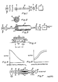
- Fig. 1 shows diagrammatically a system including the apparatus according to the invention.
- Fig. 2 shows a cross-section of the fiber of Fig. 1;
- Fig. 3 shows a system similar to that of Fig. 1;
- Fig. 4 is a fragmentary cross-section through the fiber element of Fig.3;
- Figs. 5, 6, 8, 11-14, 16 and 18 show output curves;
- Figs. 7 and 10 show double fiber assay devices (FADs);
- Fig. 9 shows a multiple FAD;
- Fig. 15 shows a single FAD of a multiple FAD;
- Fig. 17 illustrates in detail a single element of an array of several FADs;
- Fig. 19 shows a FAD having a particular sheath;
- Fig. 20 shows a means for saturating a FAD;
- Fig. 21 shows a FAD useful for a particular analyte; and
- Figs. 22 and 23 show difficult FADs designed in the form of a catheter.
- In Figure 1 there is shown one form of the apparatus of the present invention which is generally designated by the
reference numeral 10 and which, as shown in the cross-sectional view of Figure 2, consists of an inner core of fiber 11 and anouter sheath 12. The core or fiber 11 is transparent to the exciting radiation but, instead of being a conventional optical fiber such as quartz fiber, it is selected so that it is not only optically transmissive but is also permeable to components of an aqueous solution. Theouter sheath 12 is of absorptive, semi-permeable material. - To the
outer sheath 12 is applied, for example by immersion or dipping, a fluid containing the analyte under consideration, for example blood where it is desired to measure one of its low molecular weight components. If it is desired to prevent penetration by large molecules and formed elements such as erythrocytes, platelets, or white cells, the material of which thesheath 12 is constructed may be suitably selected so as to filter out such large molecules and elements. Alternatively an outer layer (not shown) may be provided which is permeable to water, and small molecules but which is impermeable to large molecules and formed elements of the blood. Thus, it is understood that one function oflayer 12 is to act as an impermeable barrier to those unwanted components of the test fluid. - When the
device 10 is immersed in the test fluid, for example, in blood, the fluid will penetrate to the core of fiber 11. Its presence may be detected by illuminating the core with (e.g.) light of a wavelength that is selectively absorbed by the analyte. Thus the diminution of light that emerges from the exit end of the fiber is proportional to the concentration of the analyte in the sample fluid. - In Figure 1 there is shown diagrammatically a system for carrying out such a determination of analyte in an aqueous solvent, including a source of
radiation 13, a focusinglens 14 and asuitable filter 15 to transmit light of the proper wavelength. At the exit end of the device is alight detector 16 and an electrical signal processor 17. The electrical signal processor amplifies the signal from the light detector and may be made from any of several well known and commercially available devices, and may include readout means of visual type and a recorder for a printed readout. - It is to be understood that the instruments of Figure 1 that are used to introduce energy into the analytical apparatus and to measure that which leaves the system can be configured in any of a number of ways depending on the use of the device. The simplicity of use and intrinsically rapid response of the invention suggests that one use will be to make bedside measurements. In such a case a portable unit with rechargeable batteries would be preferred. It is to be further understood that modern electronic data processing methods are so compact that one may further simplify the use of the analytical apparatus by utilizing electronic corrections and calibrations which permit the use of assay methods that are non-linear in their response to the analyte concentration. In fact, it is possible to assemble several analytical elements in a parallel arrangement in a single instrument.
- The letters "a" and "b" and the lead lines therefrom in Figure 1 signify the "active length" of
energy transmissive device 10. This active length is that portion of the device which is exposed to analyte, or to a product of an analyte, and along which the flow of energy is cumulatively modified by the analyte or a product of the analyte. The path from "a" to "b" (which may be continuous or segmented) is long compared to the thickness of theelement 10. - In the apparatus of Figure 1 the core 11 may be bare, i.e. devoid of a sheath. Thus where, for example, the atmosphere or water, an industrial fluid or a biological fluid contains the analyte of interest, e.g. a contaminant such as sulfur dioxide or a nitrogen oxide in stack gas or a phenolic contaminant, the material of the core 11 may be selected so that it absorbs such contaminant which modifies the flow of energy through the core, e.g. by absorption of a selected wavelength of light.
- Referring now to Figure 3, a system similar to that of Figure 1 is shown where the fiber assay device (FAD) 10: shown on a larger and exaggerated scale and with the interior exposed to show the several components including a core 25 (hereinafter designated by the letter "C") which is transmissive to ultraviolet radiation and is impermeable to fluids; and a
sheath 26 of gas permeable material containing an oxygen quenchable fluorescent dye substance. The index of refraction ns ofsheath 26 is greater than the index of refraction nc of the core. Theouter sheath 27 is oxygen permeable and is reflective. It may be impermeable to large molecules and to formed elements such as platelets and red cells in blood. - Referring to Figure 4, which is a fragmentary cross section through the FAD, molecules of fluorescent dye are indicated at 28. Ultraviolet light passes through the core and some of it is refracted into the
sheath 26 where it reacts with fluorescent molecules which emit radiation in the visible spectrum; such emission is isotropic. That visible radiation which impinges upon the interface between thesheaths sheath 26, during passage through each increment of length of the core ΔX, (X being the distance along the active length of the core) the radiation passing through the core will pick up an increment Δi of emitted light. Ai will not, of course, be constant inasmuch as the UV radiation is somewhat attenuated as it passes through thecore 25. Nevertheless a cumulative effect will occur and the intensity of emitted visible light
- When a fluid, for example blood, industrial water or river water containing oxygen (which is the analyte to be determined) is applied to the
outer sheath 27, it will penetrate to thesheath 26. The dissolved oxygen in the fluid will quench fluorescence, therefore, it will diminish the intensity of fluorescent light emitted at the output end of the core. The emitted radiation passes through theultraviolet filter 18, then through an opto-electrical detector (O-ED) 30 which acts as a transducer to convert the emitted light energy into electrical energy. The emitted electrical energy is processed in a unit 31 resulting in a digital or analog output. A suitable processor consists of amplifiers, limiters, meters, and elements for electrical logic, as are well known to those in the instrumentation business. A molecule well known for its tendency to exhibit 02 quenching of fluorescence is fluoranth- rene. - Figure 5 shows a curve typical of such an output. Advantageous features of this system include its low temperature sensitivity, and rapid response time.
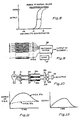
- Referring now to Figure 6, a plot of analyte concentration against output of a similar system is shown.
- The solid curve represents a mean calibration curve in the absence of other molecules. The dotted curve is the calibration curve in the presence of a molecule that may also occur in the fluid. Thus, the calibration curve shifts up or down the vertical axis as a function of the unknown concentration of contaminant, Cc. If CA is the concentration of the analyte, we may represent this phenomenon of interference by the expression:

unit 34 which is designed so as to measure the concentration of the contaminant. The output of the two fibers can be detected with equal sensitivity because the fibers are illuminated from a single light source. The two signals can be electronically subtracted as can be done in commercially available analog or digital devices indicated generally at 35. Therefore without the need for calibration the output is a measure of the concentration of analyte. - Yet another limitation of many highly sensitive assay systems (e.g. radioimmuno assay) is summarized in Figure 8. The analyte is detected by reaction with a reagent. The high specificity of the reaction leads to a steep dose response curve; i.e. for a given reagent concentration the output changes over its full range when traversing a narrow range of analyte concentration. When the range of anticipated analyte concentration is wide, as denoted bv the shaded area in Fiaure 8. one must perform several determinations, each with a different reactant concentration in order to determine the analyte concentration.
- Referring now to Figure 9, a multiple fiber assay device (MFAD) is shown consisting of n such FAD devices, each of which embodies within one of its sheaths a reagent. The reagent concentrations vary from one device to the other. It will be apparent that when these fibers are wet by a fluid that there is one reagent concentration resulting in an output which is a reflection of the analyte concentration. The other fibers either over- or underreact with the analyte yielding unmeasurable outputs. Assume that FADj (j being an integer from one to n) is optimum. The separate outputs of the FADs are converted by O-EDs to electrical outputs which are separately transmitted to a
switching device 36 controlled by amicroprocessor 37 to select the output of FADj and reject the others. - Referring now to Figure 10, a dual FAD system is shown intended for the determination of the glucose concentration of a body fluid, for example blood. As in Figure 3,
sheath 26 of each device contains an oxygen quenchable dye andsheath 27 is an oxygen permeable sheath which reflects light back into the core. Thesheath 27 also functions to prevent penetration of fluorescent molecules from the sample. Alternatively, an outermost sheath (not shown) may be employed for that purpose. One such device 36a is the control device that measures oxygen (the contaminant); and the other 36b is modified by having in the sheath 27 a quantity of glucose oxidase. Both devices are wetted with a sample simultaneously. Oxygen in both samples penetrates throughsheath 27 tosheath 26 and quenches fluorescence. However, glucose oxidase insheath 26 ofdevice 36b causes reaction of a portion of the oxygen with the glucose and therefore diminishes the oxygen available for quenching fluorescence. The rate of oxidation is proportional to the concentration of glucose. Therefore, the output of thedevice 36b will be greater than that of the device 36a and the difference is measured by the output of the device. The system includes afilter 37, OED devices 38 and aprocessor 39. - Referring now to Figure 11, the output of each O-ED in Figure 10 is plotted as a function of time following addition of a blood sample to the DFAD, presuming that the oxygen level of the blood is higher than that of ambient air. In the case of the oxygen sensor 36a the excess oxygen is lost by diffusion to the air and ultimately the output (dotted) curve reaches a steady value of fluorescence that reflects equilibration with air. However, the modified
fiber 36b consumes the oxygen more rapidly due to its reaction with the glucose in the sample, causing a greater rise in fluorescence. when all the glucose that is present in the blood has been consumed, this fiber also equilibrates with ambient air. Thus, the two curves ultimately merge. Figure 12 is a curve representing the integration of the space between the two curves and therefore its area is a measure of the total amount of glucose in the sample. - Referring now to Figure 13, a plot is shown in the case of continuous monitoring where the dual FAD device is implanted within a patient. (See also Figures 22 and 23 below and the description thereof). The first portion of the curve represents normal variations in glucose level in the blood and the large increase represents a large increase in glucose level after, for example, a patient has had a meal. The solid curve represents the output of
device 36b and the broken line curve represents the output of device 36a. Figure 14 is a plot of the difference between the curves of Figure 13, therefore of the variation with time of the glucose level of the patient. - Referring now to Figure 15, a single FAD of a multiple FAD system is shown as an example of an immunoassay described in Figure 9 above. The FAD comprises an innermost sheath 41 whose index of refraction n, is greater than the index of refraction no of the core and which contains an antigen-fluorescein complex designated as A* in quantity sufficient to fully saturate an antibody located in sheath 43.
Sheath 42 is a sheath which is hydrophilic and contains reflective particles and which is impermeable to antigen (A) when dry but permeable when wet. Sheath 43 is hydrophilic and contains as a reagent, an antibody Ab to the antigens A* and A. (A is the analyte of interest.) The outermost sheath 44 is microporous. A sample of fluid containing the antigen A is added to sheath 44. - The kinetics of diffusion and reaction of the system are as follows:
- A diffuses through sheath 44 info sheath 43 and A* diffuses through
sheath 42 into sheath 43. The following competing reversible reactions occur in sheath 43.

- The spacing of the curves in Figure 16 is arbitrary. It will be apparent that in actuality this spacing will depend upon the concentration of A* in sheath 41 and the concentration of A in the sample. By employing a bundle of FADs each containing a different concentration of A* in sheath 41, one of the devices will contain an optimum concentration of A* such that the spacing of the curves is optimum. By means of the
logic selector 45, the output of that device will be selected and the others rejected. By calibration the concentration of A in the sample may be determined. - Yet another method for utilizing the specificity and high sensitivity of immunoassays is shown by Figures 17 and 18. Figure 17 illustrates in detail a single element of an array of several FADs, each containing different concentrations of antibody Ab. The core c is permeable to the product Y of a reaction

Sheath 50 is permeable to Y but not to X; sheath S1 contains an antibody Ab and an antigen-enzyme complex A-E wherein the enzyme E is active. This complex reacts with antibody in accordance with the following reversible reaction.
Sheath 50 has a lower index of refraction than the index of refraction of core C, in order to reflect all the light along the axial path within the core. - This system is intended to measure analyte A, which is an antigen, in a fluid sample.
Sheath 51 is microporous and permeable to A. Whensheath 51 is wetted with a sample containing the antigen A, it diffuses intosheath 51 but no further. There it reacts with Ab, displacing A-E in direct proportion to their relative concentrations. The A-E that is released catalyzes the reaction, forming Y which then diffuses into the core where it is detected by light that is transmitted along the core. If the wavelength of light is selected for maximum absor- bance by Y andsheath 51 contains an excess of X the method will be highly sensitive and specific for the presence of A in the sample fluid. Figure 18 describes the electrical output of the system following the application of the sample tosheath 51. As in Figure 9 this analytical method will require the use of a switching system so as to measure the curve for the element that contains the optimum quantity of Ab-A-E. The rate of change of output from that element will then be proportional to the concentration of A in the sample. - Referring now to Figure 19, an FAD is shown comprising a core C and a
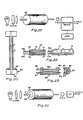
sheath 52 having a lower I refractive index than the core or containing reflective material (or surrounded by a reflective sheath, not shown). Thesheath 52 is permeable to analyte (i.e. an antigen, A) but not to higher molecular weight components of the sample. The core contains antibody Ab bonded to a dye D to form the complex Ah-D. Light at the absorption peak of the dye is transmitted through core C. The dye exhibits the property that its absorptive powers are changed when the antigen binds to Ab-D. When sample is applied to sheath 55, antigen A (the analyte of interest) diffuses through this sheath and into core C, which is selected for this purpose. The reversible reaction
- This causes a shift in the amount of light transmitted through the element. By using a set of elements with varying concentrations of Ab-D one may select the optimum element for the level of A in the fluid. Since the reaction of A with Ab-D is reversible this may be used for continuous monitoring.
- When measuring the analyte concentration in a discrete fluid sample, it is necessary to apply a reproducible volume of fluid uniformly to the analytical element described herein. While this can be achieved by a skilled operator utilizing micro pipettes, it is intended here to describe another means whereby this may be achieved in a simpler fashion. It will be seen that this is a unique feature of the elements described herein.
- Referring now to Figure 20, a means for uniformly saturating an FAD is shown which employs the phenomonen of wicking. The FAD shown consists of a core C and a single sheath S. The same means may be employed with FADs containing several sheaths and two or more FADs.
- A
base 60 is shown comprising arigid support 61. Adhered to the top of the base is ahydrophilic coating 62 which is wetted with the sample which is used in excess to that needed to wet the FAD. The sample fluid will diffuse through the base to the FAD. It will ascend by capilliary action to the top of the FAD. Provided the height of the device is not excessive, the wicking or capilliary effect will result in a uniform wetting of the sheath S. - The analytical device described herein may be adapted to permit the measurement of large molecular weight analytes that do not normally permeate sheaths in a selective fashion. Figure 21 describes such a device that is useful for determining the quantity of enzyme in a fluid sample. The core C is permeable to a dye D and is transmissive to light with a wavelength selected for maximum absorption by D. The dye D is chemically bound to a hydrophilic polymer that is incorporated into
sheath 57.Sheath 58 is permeable to D, impermeable to higher molecular weight components of the fluid, and selected from materials with a lower refractive index than the core. The chemical bond between the dye and the polymer will be selected so it can be selectively degraded by the enzyme in the fluid that one wishes to detect. Thus, for example, if one wishes to measure the concentration of esterase in plasma, utilize an ester linkage between the dye and the polymer. This can be accomplished e.g. by use of any of the dyes classed as acidic dyes, reacted with the hydroxyl groups in gelatin. - When the element is wet by a sample, D will be enzymatically released and diffuse into the core where it will be detected by a decrease in light transmission through the element. The rate of change in light transmission will be proportional to the concentration of the enzyme.
- One of the advantages of the fiber embodiment of the invention is that it can be readily incorporated in a catheter for insertion into the body, for example, into a vein or an artery. A suitable form of catheter-fiber structure is shown in Figure 22.
- Referring to Figure 22, a
catheter 70 is formed in two parts, namely atip portion 71 and a body portion 72. These are made of suitable material such as polypropylene, polyethylene, silicone rubber, polyvinyl chloride, or poly (ethylene vinylacetate) and may have a diameter of, for example, .5 to 1.5 mm, appropriate for a particular purpose such as, for example, insertion into a vein or an artery. A cylindrical fiber-shapeddevice 73 is affixed, for example, in a spiral configuration as shown, to thetip 71 such that it is exposed to the body fluid when the catheter is implanted. Thefiber 73 has protrudingtips 73a and 73b. The exposed fiber 73 (either all or a portion of it) is susceptible to penetration by an analyte and is of a construction such as that shown in any of Figures 2, 3, 7, 9, 10 or 19, hereinabove. The body 72 of the catheter is formed withparallel passages 75 into whichfiber extensions 73a and 73b are inserted, these being recessed so as to formsockets 77. Thefiber extensions 73a and 73b may be bare optical fiber or they may be coated with a protective coating. When thetip 71 and the body portion 72 are assembled in operative condition the protrudingtips 73a and 73b will be received in thesockets 77 and will be in physical and optical contact with the fiber extensions 75a, thereby providing a continuous optical path from a source of exciting radiation to the output end. - With such a catheter continuous monitoring of a body fluid is possible with an appropriate readout to inform the diagnostician, either visually or by printout or by both means.
- Referring now to Figure 23, another form of catheter is shown which comprises a
housing 80 through which an optical fiber 81 passes and which also supports anextension 82 of the optical fiber having a portion 82a exposed to body fluids. The exposed portion 82a may be constructed as in any of Figures 2, 3, 7, 9, 10 or 19 above. The projections 81 a offibers 81 and 82, project intosockets 83 in atip 84 which embodies aprism 85. When thetip 84 and thehousing 80 are brought together a continuous light path, is provided through the optical fiber 81, the prism and the optical fiber 81 a. - It will be apparent that the invention may be manifested in numerous forms and is capable of numerous applications. Structurally there are at least two elements one of which, exemplified by the transmissive core is a medium for transmitting energy in continuous form such as electro-magnetic energy, e.g. ultraviolet light or visible light, electric current (AD or DC) or sonic energy. The other element (or elements) is a sheath or sheaths. The configuration is preferably rod-life with a transmissive core in the form of a fiber typically about 10 /J.m to 1 mm in diameter with one or more sheaths surrounding the core typically about 10 /J.m to 100 /J.m in thickness. The active length of the device (i.e., the length which is wetted by the test fluid) may vary from about 0.5 cm or less to 1 meter or more. In most bioassay applications the length will not exceed about 10 cm. Departures from such dimensions are permissible. As stated above, other configurations, e.g. polygonal configurations, are permissible.
- The core, besides its transmissivity and shape, may have the following characteristics: It may be impermeable to aqueous liquids. If permeable it may contain a reagent, e.g. a dye, or it may be devoid of a dye and be a receptor for permeation by a reagent. Suitable materials for impermeable cores are quartz, polymethylmethacrylate, polycarbonate, polystyrene, etc. If the core is permeable, suitable materials are plasti cized polyvinyl chloride, polyurethanes, polypropylene, nylon, gelatin, polyvinyl alcohol, natural rubber, butyl rubber, cis- polyisoprene, poly (ethylene vinyl acetate). The index of refraction of the core, nc, may be greater or less than that of the adjacent sheath.
- The material and construction of the sheaths will depend upon their function. In all cases when a reaction occurs in a sheath or where a liquid must diffuse into, through or out of a sheath, it should be permeable to water. Permeable sheaths may be permeable to large and small molecules and to finely divided solids suspended in a liquid sample, or they may be selective with regard to permeability such that unwanted large molecules, etc. are excluded, as taught in the book by Crank and Park, "Diffusion in Polymers". One or more sheaths may contain a reagent or a precursor of a reagent and such reagent or precursor may be immobile or mobile, and it may undergo a reaction such as enzymatic cleavage to render its product mobile, or it may undergo a reaction such as antibody-antigen reaction which makes it immobile. All such physical states of sheath material and reagents are possible and methods of synthesis or forming are well known to those practiced in the art.
- Elements of the dimensions suitable for this invention e.g. (1-100 u.m diameter) can be made by normal fiber-forming techniques; the Encyclopedia of Polymer Science and Technology provides an adequate description of these techniques. Briefly, there are three major techniques: melt forming, wet forming, and dry forming. Melt forming is used for thermoplastic polymers (e.g. polypropylene) that exhibit a low viscosity when heated above their melting point. Wet process forming consists of extruding a solution of the polymer in a solvent and passing the fiber through a bath of a second solvent. This bath solvent has the property that it will dissolve the polymer solvent, but not the polymer; thus the solvent is extracted by the bath solvent, leaving a pure polymer fiber. Dry forming consists of extruding a solution of polymer and volatile solvent into a heated air stream, where the solvent evaporates.
- Adaptations of these processes can be used to coat the core fiber with the sheaths. If the central fiber is made from a high melting point material (e.g. glass), one could coat it with a melted polymer. It is more likely that one will use polymer solutions, especially when it is necessary to incorporate chemicals that are used to react with analyte or otherwise participate in the required chemical analysis. Many such reagents degrade under conditions of high temperature.
- If, for example, one wanted to form an assym- metric microporous membrane as the outer sheath as is required for the enzyme assay described above (Figure 21), one could use wet forming. The polymer and dye-polymer conjugate would be dissolved in a solvent and coated onto the fiber by pulling the fiber (C, coated with sheath 58) through an orifice that has the solution on the upstream side. On the downstream side is a bath with a solvent that is selected to elute the primary solvent leaving a
polymer sheath 57 that has microscopic holes. The bath solvent is selected so as to be non-solvent for both the polymer and the dye-polymer conjugate. - Once formed as a continuous, long coated fiber, it will be cut into short lengths and mounted in a holder, whose purpose is to align the ends of the fiber into a reproducible position, to provide a simple means to insert the fiber into the instrument (cf. Figure 1), and a means to protect the fiber during storage and use. The housing could also be within a catheter for use as a monitoring instrument as shown in Figures 22 and 23. The catheter could be inserted into the fluid or body cavity of interest; it contains highly conductive input and output fibers that are coupled to each end of the coated fiber assay system so as to introduce exciting radiation and to recover the analyte-modified radiation. These housings will generally be made of plastic material and are understood to be fabricated by the standard methods available, namely, injection molding, transfer molding, extrusion, epoxy molding or heat forming.
- Reagents, reagent precursors, reflective material, etc. which may be incorporated in various sheaths include the following: enzymes, 02- quenchable fluorescent molecules (e.g. fluoroanth- rene), antibodies, dyes, fluorescent dyes, reflective materials (Ti02, Si02, etc.) dye-polymers products. These and other reagents, reagent pre-cursors and reflective materials are well known to those skilled in the art.
- It will therefore be apparent that new and useful apparatus and methods are provided for chemical and biochemical analyses.
Claims (12)
Applications Claiming Priority (2)
| Application Number | Priority Date | Filing Date | Title |
|---|---|---|---|
| US76984 | 1979-09-20 | ||
| US06/076,984 US4321057A (en) | 1979-09-20 | 1979-09-20 | Method for quantitative analysis using optical fibers |
Publications (3)
| Publication Number | Publication Date |
|---|---|
| EP0036017A1 EP0036017A1 (en) | 1981-09-23 |
| EP0036017A4 EP0036017A4 (en) | 1982-02-05 |
| EP0036017B1 true EP0036017B1 (en) | 1991-02-27 |
Family
ID=22135427
Family Applications (1)
| Application Number | Title | Priority Date | Filing Date |
|---|---|---|---|
| EP80902002A Expired - Lifetime EP0036017B1 (en) | 1979-09-20 | 1981-04-08 | Apparatus for analysis |
Country Status (6)
| Country | Link |
|---|---|
| US (1) | US4321057A (en) |
| EP (1) | EP0036017B1 (en) |
| JP (4) | JPH0363024B2 (en) |
| CA (1) | CA1154827A (en) |
| DE (1) | DE3072190D1 (en) |
| WO (1) | WO1981000912A1 (en) |
Families Citing this family (105)
| Publication number | Priority date | Publication date | Assignee | Title |
|---|---|---|---|---|
| EP0075353B1 (en) * | 1981-09-18 | 1987-08-19 | Battelle Memorial Institute | Method and apparatus for the determination of species in solution with an optical wave-guide |
| US4467206A (en) * | 1981-12-14 | 1984-08-21 | Extracorporeal Medical Specialties, Inc. | Method and apparatus for the irradiation of fluids |
| US4582809A (en) * | 1982-06-14 | 1986-04-15 | Myron J. Block | Apparatus including optical fiber for fluorescence immunoassay |
| US4447546A (en) * | 1982-08-23 | 1984-05-08 | Myron J. Block | Fluorescent immunoassay employing optical fiber in capillary tube |
| DE3376685D1 (en) * | 1982-12-21 | 1988-06-23 | Ares Serono Nv | Assay technique |
| CA1261717A (en) * | 1982-12-23 | 1989-09-26 | John R. Bacon | Method and apparatus for oxygen determination |
| US4558014A (en) * | 1983-06-13 | 1985-12-10 | Myron J. Block | Assay apparatus and methods |
| DE3344019C2 (en) * | 1983-12-06 | 1995-05-04 | Max Planck Gesellschaft | Device for optically measuring the concentration of a component contained in a sample |
| US4668636A (en) * | 1984-11-06 | 1987-05-26 | Battelle Memorial Institute | Analytical assembly usable in apparatuses for optically determining species in solution |
| US4650329A (en) * | 1984-11-29 | 1987-03-17 | The United States Of America As Represented By The Secretary Of The Navy | Optical 3-d signature device for detecting chemical agents |
| US4713347A (en) * | 1985-01-14 | 1987-12-15 | Sensor Diagnostics, Inc. | Measurement of ligand/anti-ligand interactions using bulk conductance |
| EP0190830A3 (en) * | 1985-02-04 | 1988-04-27 | Gould Inc. | Single optical fiber sensor for measuring the partial pressure of oxygen |
| US4752115A (en) * | 1985-02-07 | 1988-06-21 | Spectramed, Inc. | Optical sensor for monitoring the partial pressure of oxygen |
| US4666672A (en) * | 1985-04-08 | 1987-05-19 | University Of California | Optrode for sensing hydrocarbons |
| JPH0746110B2 (en) * | 1985-05-28 | 1995-05-17 | オリンパス光学工業株式会社 | Immunological measurement method |
| DE3680999D1 (en) * | 1985-05-29 | 1991-09-26 | Artificial Sensing Instr Asi A | OPTICAL SENSOR FOR SELECTIVE DETECTION OF SUBSTANCES AND DETECTION OF REFRIGERATION CHANGES IN MEASURING SUBSTANCES. |
| US5034189A (en) * | 1985-08-27 | 1991-07-23 | The Regents Of The University Of California | Fluorescent probe for rapid measurement of analyte concentration |
| US4654532A (en) * | 1985-09-09 | 1987-03-31 | Ord, Inc. | Apparatus for improving the numerical aperture at the input of a fiber optics device |
| US4671938A (en) * | 1985-09-09 | 1987-06-09 | Ciba-Corning Diagnostics, Corp. | Immunoassay apparatus |
| US4945245A (en) * | 1986-01-14 | 1990-07-31 | Levin Herman W | Evanescent wave background fluorescence/absorbance detection |
| US4798738A (en) * | 1986-10-10 | 1989-01-17 | Cardiovascular Devices, Inc. | Micro sensor |
| US4800886A (en) * | 1986-07-14 | 1989-01-31 | C. R. Bard, Inc. | Sensor for measuring the concentration of a gaseous component in a fluid by absorption |
| US4861727A (en) * | 1986-09-08 | 1989-08-29 | C. R. Bard, Inc. | Luminescent oxygen sensor based on a lanthanide complex |
| US4717545A (en) * | 1986-09-11 | 1988-01-05 | Miles Inc. | Device and method for chemical analysis of fluids with a reagent coated light source |
| US4886338A (en) * | 1986-10-10 | 1989-12-12 | Minnesota Mining And Manufacturing Company | Optical fiber event sensor |
| US4849340A (en) * | 1987-04-03 | 1989-07-18 | Cardiovascular Diagnostics, Inc. | Reaction system element and method for performing prothrombin time assay |
| BE1000572A4 (en) * | 1987-05-20 | 1989-02-07 | Block Myron J | Appts. for analysing polynucleotide in liq. sample - using internal reflection cell coated with complementary single strand sequences and selective fluorescent dye |
| US4834496A (en) * | 1987-05-22 | 1989-05-30 | American Telephone And Telegraph Company, At&T Bell Laboratories | Optical fiber sensors for chemical detection |
| US4909990A (en) * | 1987-09-02 | 1990-03-20 | Myron J. Block | Immunoassay apparatus |
| US4974929A (en) * | 1987-09-22 | 1990-12-04 | Baxter International, Inc. | Fiber optical probe connector for physiologic measurement devices |
| GB8723359D0 (en) * | 1987-10-05 | 1987-11-11 | Atomic Energy Authority Uk | Sensor |
| US4994396A (en) * | 1987-12-14 | 1991-02-19 | The Dow Chemical Company | Method for measuring the concentration or partial pressure of oxygen |
| WO1989007254A1 (en) * | 1988-01-28 | 1989-08-10 | Spectran Corporation | Infrared transmitting probe and assays using same |
| US5152962A (en) * | 1988-07-22 | 1992-10-06 | Ord Corp. | Immunoassay apparatus |
| GB2228082A (en) * | 1989-01-13 | 1990-08-15 | Marconi Gec Ltd | Gas or liquid chemical sensor |
| US5244810A (en) * | 1990-01-12 | 1993-09-14 | Gottlieb Amos J | Analytical method |
| US5102625A (en) * | 1990-02-16 | 1992-04-07 | Boc Health Care, Inc. | Apparatus for monitoring a chemical concentration |
| US5081042A (en) * | 1990-03-20 | 1992-01-14 | Minnesota Mining And Manufacturing Company | Ionic component sensor and method for making and using same |
| US5081041A (en) * | 1990-04-03 | 1992-01-14 | Minnesota Mining And Manufacturing Company | Ionic component sensor and method for making and using same |
| US5054882A (en) * | 1990-08-10 | 1991-10-08 | Puritan-Bennett Corporation | Multiple optical fiber event sensor and method of manufacture |
| US5166990A (en) * | 1990-08-10 | 1992-11-24 | Puritan-Bennett Corporation | Multiple optical fiber event sensor and method of manufacture |
| US5140155A (en) * | 1990-10-17 | 1992-08-18 | Edjewise Sensor Products, Inc. | Fiber optic sensor with dual condition-responsive beams |
| US5144690A (en) * | 1990-12-03 | 1992-09-01 | Corning Incorporated | Optical fiber sensor with localized sensing regions |
| US5192510A (en) * | 1991-01-30 | 1993-03-09 | E. I. Du Pont De Nemours And Company | Apparatus for performing fluorescent assays which separates bulk and evanescent fluorescence |
| DE9110757U1 (en) * | 1991-08-30 | 1992-02-13 | Klein, Rainer, 5840 Schwerte, De | |
| US5453248A (en) * | 1992-03-09 | 1995-09-26 | Optical Sensors Incorporated | Cross-linked gas permeable membrane of a cured perfluorinated urethane polymer, and optical gas sensors fabricated therewith |
| US5308771A (en) * | 1992-04-13 | 1994-05-03 | Geo-Centers, Inc. | Chemical sensors |
| US5326531A (en) * | 1992-12-11 | 1994-07-05 | Puritan-Bennett Corporation | CO2 sensor using a hydrophilic polyurethane matrix and process for manufacturing |
| US5436167A (en) * | 1993-04-13 | 1995-07-25 | Board Of Regents, University Of Texas System | Fiber optics gas sensor |
| US5919712A (en) | 1993-05-18 | 1999-07-06 | University Of Utah Research Foundation | Apparatus and methods for multi-analyte homogeneous fluoro-immunoassays |
| US5677196A (en) * | 1993-05-18 | 1997-10-14 | University Of Utah Research Foundation | Apparatus and methods for multi-analyte homogeneous fluoro-immunoassays |
| US5413939A (en) * | 1993-06-29 | 1995-05-09 | First Medical, Inc. | Solid-phase binding assay system for interferometrically measuring analytes bound to an active receptor |
| US5628310A (en) * | 1995-05-19 | 1997-05-13 | Joseph R. Lakowicz | Method and apparatus to perform trans-cutaneous analyte monitoring |
| US5639668A (en) * | 1995-09-14 | 1997-06-17 | Boehringer Mannheim Corporation | Optical apparatus for performing an immunoassay |
| US5854863A (en) * | 1996-03-15 | 1998-12-29 | Erb; Judith | Surface treatment and light injection method and apparatus |
| US6611634B2 (en) | 1996-03-19 | 2003-08-26 | University Of Utah Research Foundation | Lens and associatable flow cell |
| US5809185A (en) * | 1996-04-26 | 1998-09-15 | Mitchell; Ralph | Sensor for detecting microorganisms |
| US7335164B2 (en) | 1996-07-15 | 2008-02-26 | Ntc Technology, Inc. | Multiple function airway adapter |
| US20070225612A1 (en) * | 1996-07-15 | 2007-09-27 | Mace Leslie E | Metabolic measurements system including a multiple function airway adapter |
| US6815211B1 (en) | 1998-08-04 | 2004-11-09 | Ntc Technology | Oxygen monitoring methods and apparatus (I) |
| US6325978B1 (en) | 1998-08-04 | 2001-12-04 | Ntc Technology Inc. | Oxygen monitoring and apparatus |
| JP3200024B2 (en) * | 1997-02-19 | 2001-08-20 | 哲雄 長野 | Diaminofluorescein derivative |
| DE19734618A1 (en) * | 1997-08-09 | 1999-02-11 | Boehringer Mannheim Gmbh | Analyser for in-vivo determination of analytes in body of patient |
| US6922576B2 (en) * | 1998-06-19 | 2005-07-26 | Becton, Dickinson And Company | Micro optical sensor device |
| US6290912B1 (en) * | 1998-07-14 | 2001-09-18 | Bayer Corporation | Read head for luminometer |
| US6535753B1 (en) * | 1998-08-20 | 2003-03-18 | Microsense International, Llc | Micro-invasive method for painless detection of analytes in extra-cellular space |
| US6205263B1 (en) * | 1999-06-16 | 2001-03-20 | Intelligent Optical Systems | Distributed optical fiber sensor with controlled response |
| US8111401B2 (en) | 1999-11-05 | 2012-02-07 | Robert Magnusson | Guided-mode resonance sensors employing angular, spectral, modal, and polarization diversity for high-precision sensing in compact formats |
| US7167615B1 (en) | 1999-11-05 | 2007-01-23 | Board Of Regents, The University Of Texas System | Resonant waveguide-grating filters and sensors and methods for making and using same |
| EP2189783A1 (en) | 2000-08-09 | 2010-05-26 | Artificial Sensing Instruments ASI AG | Waveguide grid structure and optical measuring assembly |
| US7094595B2 (en) | 2000-10-30 | 2006-08-22 | Sru Biosystems, Inc. | Label-free high-throughput optical technique for detecting biomolecular interactions |
| JP3429282B2 (en) * | 2001-02-02 | 2003-07-22 | リサーチ・インターナショナル・インコーポレーテッド | Automated system and sample analysis method |
| GB0117230D0 (en) * | 2001-07-14 | 2001-09-05 | Marconi Applied Technologies | Detecting analytes |
| US7537731B2 (en) * | 2001-10-19 | 2009-05-26 | Panasonic Corporation | Specific binding analysis device |
| US7632671B2 (en) * | 2001-11-29 | 2009-12-15 | Sun-Wing Tong | Molecular detection and assay by electrobiochip micro-array |
| JP2004003976A (en) * | 2002-04-05 | 2004-01-08 | Matsushita Electric Ind Co Ltd | Method for analyzing specific bond, and device used for the same |
| JP3653536B2 (en) * | 2002-06-21 | 2005-05-25 | 独立行政法人航空宇宙技術研究所 | Optical oxygen concentration measuring method and optical oxygen concentration measuring sensor |
| AU2003251983A1 (en) | 2002-07-08 | 2004-01-23 | Ossur Engineering, Inc. | Socket liner incorporating sensors to monitor amputee progress |
| US7496245B2 (en) * | 2004-08-20 | 2009-02-24 | Research International, Inc. | Misalignment compensating optical sensor and method |
| US7651869B2 (en) * | 2006-03-14 | 2010-01-26 | Research International, Inc. | Optical assay apparatus and methods |
| US8126554B2 (en) * | 2006-05-17 | 2012-02-28 | Cardiac Pacemakers, Inc. | Implantable medical device with chemical sensor and related methods |
| JP4939923B2 (en) * | 2006-12-27 | 2012-05-30 | 富士フイルム株式会社 | Hazardous substance removing material, hazardous substance removing method, nonwoven fabric |
| JP2010532998A (en) | 2007-07-11 | 2010-10-21 | エス アール ユー バイオシステムズ,インコーポレイテッド | Method for identifying modulators of ion channels |
| US9134307B2 (en) | 2007-07-11 | 2015-09-15 | X-Body, Inc. | Method for determining ion channel modulating properties of a test reagent |
| US20090021740A1 (en) * | 2007-07-17 | 2009-01-22 | Chung Yuan Christian University | Optical sensor and method for measuring blood gas |
| US9044178B2 (en) * | 2007-08-30 | 2015-06-02 | Pepex Biomedical, Llc | Electrochemical sensor and method for manufacturing |
| US8702932B2 (en) | 2007-08-30 | 2014-04-22 | Pepex Biomedical, Inc. | Electrochemical sensor and method for manufacturing |
| US8951377B2 (en) | 2008-11-14 | 2015-02-10 | Pepex Biomedical, Inc. | Manufacturing electrochemical sensor module |
| US9445755B2 (en) | 2008-11-14 | 2016-09-20 | Pepex Biomedical, Llc | Electrochemical sensor module |
| US8506740B2 (en) | 2008-11-14 | 2013-08-13 | Pepex Biomedical, Llc | Manufacturing electrochemical sensor module |
| US8463083B2 (en) | 2009-01-30 | 2013-06-11 | Claudio Oliveira Egalon | Side illuminated multi point multi parameter optical fiber sensor |
| CN101825744B (en) * | 2010-04-02 | 2012-07-25 | 电子科技大学 | High-nonlinearity composite-structure micro-nano optical wave conducting wire and preparation method thereof |
| WO2012162151A2 (en) | 2011-05-20 | 2012-11-29 | Pepex Biomedical, Inc. | Manufacturing electrochemical sensor modules |
| CN104918551B (en) | 2012-12-03 | 2019-07-26 | Pepex生物医药有限公司 | Sensor module and the method for using sensor module |
| WO2014089331A1 (en) | 2012-12-06 | 2014-06-12 | Ossur Hf | Electrical stimulation for orthopedic devices |
| JP6234768B2 (en) * | 2013-10-21 | 2017-11-22 | 日東電工株式会社 | Optical waveguide and SPR sensor cell and colorimetric sensor cell using the optical waveguide |
| EP3152559B1 (en) | 2014-06-04 | 2020-12-02 | Pepex Biomedical, Inc. | Electrochemical sensors made using advanced printing technology |
| US10716500B2 (en) | 2015-06-29 | 2020-07-21 | Cardiac Pacemakers, Inc. | Systems and methods for normalization of chemical sensor data based on fluid state changes |
| JP6833371B2 (en) * | 2016-07-12 | 2021-02-24 | 浜松ホトニクス株式会社 | Optical output monitoring device, optical output monitoring method, protective cap and adapter |
| CN108968976B (en) | 2017-05-31 | 2022-09-13 | 心脏起搏器股份公司 | Implantable medical device with chemical sensor |
| CN109381195B (en) | 2017-08-10 | 2023-01-10 | 心脏起搏器股份公司 | Systems and methods including electrolyte sensor fusion |
| CN109419515B (en) | 2017-08-23 | 2023-03-24 | 心脏起搏器股份公司 | Implantable chemical sensor with staged activation |
| CN109864746B (en) | 2017-12-01 | 2023-09-29 | 心脏起搏器股份公司 | Multimode analyte sensor for medical devices |
| CN109864747B (en) | 2017-12-05 | 2023-08-25 | 心脏起搏器股份公司 | Multimode analyte sensor optoelectronic interface |
| WO2023141156A1 (en) * | 2022-01-18 | 2023-07-27 | Solaris Biosciences, Inc. | Systems and methods for membrane-based assaying |
Family Cites Families (19)
| Publication number | Priority date | Publication date | Assignee | Title |
|---|---|---|---|---|
| US3068739A (en) * | 1958-06-23 | 1962-12-18 | American Optical Corp | Flexible optical probe |
| US3404962A (en) * | 1964-10-22 | 1968-10-08 | Honeywell Inc | Apparatus for detecting a constituent in a mixture |
| US3526480A (en) * | 1966-12-15 | 1970-09-01 | Xerox Corp | Automated chemical analyzer |
| US3866599A (en) * | 1972-01-21 | 1975-02-18 | Univ Washington | Fiberoptic catheter |
| US3817706A (en) * | 1972-10-16 | 1974-06-18 | Searle & Co | Fluorescence quantitative thin layer chromatographic method |
| US3932133A (en) * | 1973-07-31 | 1976-01-13 | Olympus Optical Co., Ltd. | System for detecting the particular chemical component of a test fluid |
| US3992158A (en) * | 1973-08-16 | 1976-11-16 | Eastman Kodak Company | Integral analytical element |
| US3907503A (en) * | 1974-01-21 | 1975-09-23 | Miles Lab | Test system |
| US3905767A (en) * | 1974-01-30 | 1975-09-16 | Miles Lab | Process for qualitative analysis or quantitation of antigens or antibodies |
| CA1054034A (en) * | 1975-06-20 | 1979-05-08 | Barbara J. Bruschi | Multilayer analytical element |
| US4042335A (en) * | 1975-07-23 | 1977-08-16 | Eastman Kodak Company | Integral element for analysis of liquids |
| US3998591A (en) * | 1975-09-26 | 1976-12-21 | Leeds & Northrup Company | Spectrochemical analyzer using surface-bound color reagents |
| US4050895A (en) * | 1975-09-26 | 1977-09-27 | Monsanto Research Corporation | Optical analytical device, waveguide and method |
| SE394910B (en) * | 1975-10-29 | 1977-07-18 | Pharmacia Fine Chemicals Ab | OPTICAL ANALYSIS KIT AND DEVICE |
| US4050898A (en) * | 1976-04-26 | 1977-09-27 | Eastman Kodak Company | Integral analytical element |
| US4106909A (en) * | 1976-09-20 | 1978-08-15 | Monsanto Research Corporation | Chemical analysis with coated, light waveguide under humidity control |
| US4080075A (en) * | 1976-09-20 | 1978-03-21 | Foresight Enterprises, Inc. | Compensated densitometer |
| DE2744678C3 (en) * | 1977-09-30 | 1980-08-07 | Dr. Bruno Lange Gmbh, 1000 Berlin | Device for diagnosing various symptoms of illness and for monitoring the course of a therapy |
| US4200110A (en) * | 1977-11-28 | 1980-04-29 | United States Of America | Fiber optic pH probe |
-
1979
- 1979-09-20 US US06/076,984 patent/US4321057A/en not_active Expired - Lifetime
-
1980
- 1980-09-18 CA CA000360468A patent/CA1154827A/en not_active Expired
- 1980-09-19 WO PCT/US1980/001210 patent/WO1981000912A1/en active IP Right Grant
- 1980-09-19 DE DE8080902002T patent/DE3072190D1/en not_active Expired - Fee Related
- 1980-09-19 JP JP55502442A patent/JPH0363024B2/ja not_active Expired - Lifetime
-
1981
- 1981-04-08 EP EP80902002A patent/EP0036017B1/en not_active Expired - Lifetime
-
1990
- 1990-12-19 JP JP2403924A patent/JP2685655B2/en not_active Expired - Lifetime
- 1990-12-19 JP JP2403925A patent/JP2622430B2/en not_active Expired - Lifetime
- 1990-12-19 JP JP2403923A patent/JP2685654B2/en not_active Expired - Lifetime
Also Published As
| Publication number | Publication date |
|---|---|
| JPH08226894A (en) | 1996-09-03 |
| JP2685654B2 (en) | 1997-12-03 |
| JPH08201389A (en) | 1996-08-09 |
| JPH08201390A (en) | 1996-08-09 |
| JPH0363024B2 (en) | 1991-09-27 |
| US4321057A (en) | 1982-03-23 |
| EP0036017A1 (en) | 1981-09-23 |
| JP2685655B2 (en) | 1997-12-03 |
| JPS56501297A (en) | 1981-09-10 |
| EP0036017A4 (en) | 1982-02-05 |
| DE3072190D1 (en) | 1991-04-04 |
| JP2622430B2 (en) | 1997-06-18 |
| WO1981000912A1 (en) | 1981-04-02 |
| CA1154827A (en) | 1983-10-04 |
Similar Documents
| Publication | Publication Date | Title |
|---|---|---|
| EP0036017B1 (en) | Apparatus for analysis | |
| US4399099A (en) | Optical fiber apparatus for quantitative analysis | |
| EP1766376B1 (en) | Method and light guide test sensor for determining an analyte in a fluid sample | |
| EP0909946B1 (en) | Chemical sensing method and apparatus employing liquid-core optical fibers | |
| US5640470A (en) | Fiber-optic detectors with terpolymeric analyte-permeable matrix coating | |
| CA1310566C (en) | Element and method for performing biological assays accurately, rapidlyand simply | |
| US5143066A (en) | Optical fiber sensors for continuous monitoring of biochemicals and related method | |
| US5034189A (en) | Fluorescent probe for rapid measurement of analyte concentration | |
| US5859937A (en) | Minimally invasive sensor | |
| US6534011B1 (en) | Device for detecting biochemical or chemical substances by fluorescence excitation | |
| EP0457292A2 (en) | Improved configuration fiber-optic blood gas sensor bundle and method of making | |
| Wolfbeis | Fibre-optic sensors in biomedical sciences | |
| JP2002501193A (en) | Optical sensor and operation method | |
| KR20020063581A (en) | Test element analysis system | |
| Meadows | Recent developments with biosensing technology and applications in the pharmaceutical industry | |
| JPS61182556A (en) | Non-segment continuous fluid analysis method on basis of interaction of fixing material positioned in flow cell and radiation | |
| US6011882A (en) | Chemical sensing techniques employing liquid-core optical fibers | |
| JP2936029B2 (en) | Equipment for measuring the flow of substances | |
| JPH0250428B2 (en) | ||
| EP0490993A1 (en) | Flow optrode | |
| Dybko et al. | Fiber optic probe for monitoring of drinking water | |
| Wolfbeis | Capillary waveguide sensors | |
| JPH02502311A (en) | Modular fiber optic chemical sensor | |
| CN100565190C (en) | Biochemical substances method for sensing and biology sensor optical sensing structure | |
| Saari | Trends in fiber optic sensor development |
Legal Events
| Date | Code | Title | Description |
|---|---|---|---|
| PUAI | Public reference made under article 153(3) epc to a published international application that has entered the european phase |
Free format text: ORIGINAL CODE: 0009012 |
|
| AK | Designated contracting states |
Designated state(s): CH DE FR GB NL SE |
|
| 17P | Request for examination filed |
Effective date: 19810722 |
|
| GRAA | (expected) grant |
Free format text: ORIGINAL CODE: 0009210 |
|
| AK | Designated contracting states |
Kind code of ref document: B1 Designated state(s): CH DE FR GB LI NL SE |
|
| REF | Corresponds to: |
Ref document number: 3072190 Country of ref document: DE Date of ref document: 19910404 |
|
| ET | Fr: translation filed | ||
| PLBE | No opposition filed within time limit |
Free format text: ORIGINAL CODE: 0009261 |
|
| STAA | Information on the status of an ep patent application or granted ep patent |
Free format text: STATUS: NO OPPOSITION FILED WITHIN TIME LIMIT |
|
| 26N | No opposition filed | ||
| REG | Reference to a national code |
Ref country code: GB Ref legal event code: 727 |
|
| NLS | Nl: assignments of ep-patents |
Owner name: ELLEN J. BUCKLES GEB. WISE TE MOUNTAIN VIEW, CALIF |
|
| NLS | Nl: assignments of ep-patents |
Owner name: BETA SENSORS PARTNERS TE MOUNTAIN VIEW, CALIFORNIE |
|
| NLS | Nl: assignments of ep-patents | ||
| NLS | Nl: assignments of ep-patents |
Owner name: PURITAN-BENETT CORPORATION TE OVERLAND PARK, KANSA |
|
| REG | Reference to a national code |
Ref country code: GB Ref legal event code: 727A |
|
| PGFP | Annual fee paid to national office [announced via postgrant information from national office to epo] |
Ref country code: SE Payment date: 19920811 Year of fee payment: 13 |
|
| REG | Reference to a national code |
Ref country code: FR Ref legal event code: TP |
|
| PGFP | Annual fee paid to national office [announced via postgrant information from national office to epo] |
Ref country code: CH Payment date: 19920925 Year of fee payment: 13 |
|
| REG | Reference to a national code |
Ref country code: GB Ref legal event code: 727A |
|
| REG | Reference to a national code |
Ref country code: GB Ref legal event code: 732 |
|
| REG | Reference to a national code |
Ref country code: CH Ref legal event code: PVP Owner name: ELLEN J. WISE Ref country code: CH Ref legal event code: PUE Owner name: ELLEN J. WISE TRANSFER- PURITAN-BENNETT CORPORATIO |
|
| REG | Reference to a national code |
Ref country code: GB Ref legal event code: 727B |
|
| REG | Reference to a national code |
Ref country code: GB Ref legal event code: SP |
|
| PG25 | Lapsed in a contracting state [announced via postgrant information from national office to epo] |
Ref country code: SE Effective date: 19930920 |
|
| PG25 | Lapsed in a contracting state [announced via postgrant information from national office to epo] |
Ref country code: LI Effective date: 19930930 Ref country code: CH Effective date: 19930930 |
|
| REG | Reference to a national code |
Ref country code: CH Ref legal event code: PL Ref country code: CH Ref legal event code: AUV Free format text: LE BREVET CI-DESSUS EST TOMBE EN DECHEANCE, FAUTE DE PAIEMENT, DE LA 14E ANNUITE. |
|
| EUG | Se: european patent has lapsed |
Ref document number: 80902002.7 Effective date: 19940410 |
|
| PGFP | Annual fee paid to national office [announced via postgrant information from national office to epo] |
Ref country code: NL Payment date: 19950707 Year of fee payment: 16 |
|
| PGFP | Annual fee paid to national office [announced via postgrant information from national office to epo] |
Ref country code: GB Payment date: 19950807 Year of fee payment: 16 |
|
| PGFP | Annual fee paid to national office [announced via postgrant information from national office to epo] |
Ref country code: FR Payment date: 19950908 Year of fee payment: 16 |
|
| PGFP | Annual fee paid to national office [announced via postgrant information from national office to epo] |
Ref country code: DE Payment date: 19950928 Year of fee payment: 16 |
|
| PG25 | Lapsed in a contracting state [announced via postgrant information from national office to epo] |
Ref country code: GB Effective date: 19960919 |
|
| PG25 | Lapsed in a contracting state [announced via postgrant information from national office to epo] |
Ref country code: FR Effective date: 19960930 |
|
| PG25 | Lapsed in a contracting state [announced via postgrant information from national office to epo] |
Ref country code: NL Effective date: 19970401 |
|
| GBPC | Gb: european patent ceased through non-payment of renewal fee |
Effective date: 19960919 |
|
| NLV4 | Nl: lapsed or anulled due to non-payment of the annual fee |
Effective date: 19970401 |
|
| PG25 | Lapsed in a contracting state [announced via postgrant information from national office to epo] |
Ref country code: DE Effective date: 19970603 |
|
| REG | Reference to a national code |
Ref country code: FR Ref legal event code: ST |
|
| REG | Reference to a national code |
Ref country code: FR Ref legal event code: ST |