EP0036764A2 - A semiconductor device with a V-groove insulating isolation structure and a method of manufacturing such a device - Google Patents
A semiconductor device with a V-groove insulating isolation structure and a method of manufacturing such a device Download PDFInfo
- Publication number
- EP0036764A2 EP0036764A2 EP81301189A EP81301189A EP0036764A2 EP 0036764 A2 EP0036764 A2 EP 0036764A2 EP 81301189 A EP81301189 A EP 81301189A EP 81301189 A EP81301189 A EP 81301189A EP 0036764 A2 EP0036764 A2 EP 0036764A2
- Authority
- EP
- European Patent Office
- Prior art keywords
- semiconductor
- groove
- region
- layer
- polycrystal
- Prior art date
- Legal status (The legal status is an assumption and is not a legal conclusion. Google has not performed a legal analysis and makes no representation as to the accuracy of the status listed.)
- Granted
Links
Images


Classifications
-
- H—ELECTRICITY
- H01—ELECTRIC ELEMENTS
- H01L—SEMICONDUCTOR DEVICES NOT COVERED BY CLASS H10
- H01L21/00—Processes or apparatus adapted for the manufacture or treatment of semiconductor or solid state devices or of parts thereof
- H01L21/70—Manufacture or treatment of devices consisting of a plurality of solid state components formed in or on a common substrate or of parts thereof; Manufacture of integrated circuit devices or of parts thereof
- H01L21/71—Manufacture of specific parts of devices defined in group H01L21/70
- H01L21/76—Making of isolation regions between components
- H01L21/763—Polycrystalline semiconductor regions
-
- H—ELECTRICITY
- H01—ELECTRIC ELEMENTS
- H01L—SEMICONDUCTOR DEVICES NOT COVERED BY CLASS H10
- H01L21/00—Processes or apparatus adapted for the manufacture or treatment of semiconductor or solid state devices or of parts thereof
- H01L21/02—Manufacture or treatment of semiconductor devices or of parts thereof
- H01L21/04—Manufacture or treatment of semiconductor devices or of parts thereof the devices having at least one potential-jump barrier or surface barrier, e.g. PN junction, depletion layer or carrier concentration layer
- H01L21/18—Manufacture or treatment of semiconductor devices or of parts thereof the devices having at least one potential-jump barrier or surface barrier, e.g. PN junction, depletion layer or carrier concentration layer the devices having semiconductor bodies comprising elements of Group IV of the Periodic System or AIIIBV compounds with or without impurities, e.g. doping materials
- H01L21/26—Bombardment with radiation
- H01L21/263—Bombardment with radiation with high-energy radiation
- H01L21/268—Bombardment with radiation with high-energy radiation using electromagnetic radiation, e.g. laser radiation
-
- H—ELECTRICITY
- H01—ELECTRIC ELEMENTS
- H01L—SEMICONDUCTOR DEVICES NOT COVERED BY CLASS H10
- H01L21/00—Processes or apparatus adapted for the manufacture or treatment of semiconductor or solid state devices or of parts thereof
- H01L21/70—Manufacture or treatment of devices consisting of a plurality of solid state components formed in or on a common substrate or of parts thereof; Manufacture of integrated circuit devices or of parts thereof
- H01L21/71—Manufacture of specific parts of devices defined in group H01L21/70
- H01L21/76—Making of isolation regions between components
-
- H—ELECTRICITY
- H01—ELECTRIC ELEMENTS
- H01L—SEMICONDUCTOR DEVICES NOT COVERED BY CLASS H10
- H01L21/00—Processes or apparatus adapted for the manufacture or treatment of semiconductor or solid state devices or of parts thereof
- H01L21/70—Manufacture or treatment of devices consisting of a plurality of solid state components formed in or on a common substrate or of parts thereof; Manufacture of integrated circuit devices or of parts thereof
- H01L21/71—Manufacture of specific parts of devices defined in group H01L21/70
- H01L21/768—Applying interconnections to be used for carrying current between separate components within a device comprising conductors and dielectrics
- H01L21/76838—Applying interconnections to be used for carrying current between separate components within a device comprising conductors and dielectrics characterised by the formation and the after-treatment of the conductors
- H01L21/76886—Modifying permanently or temporarily the pattern or the conductivity of conductive members, e.g. formation of alloys, reduction of contact resistances
- H01L21/76888—By rendering at least a portion of the conductor non conductive, e.g. oxidation
-
- H—ELECTRICITY
- H01—ELECTRIC ELEMENTS
- H01L—SEMICONDUCTOR DEVICES NOT COVERED BY CLASS H10
- H01L23/00—Details of semiconductor or other solid state devices
- H01L23/52—Arrangements for conducting electric current within the device in operation from one component to another, i.e. interconnections, e.g. wires, lead frames
- H01L23/522—Arrangements for conducting electric current within the device in operation from one component to another, i.e. interconnections, e.g. wires, lead frames including external interconnections consisting of a multilayer structure of conductive and insulating layers inseparably formed on the semiconductor body
- H01L23/525—Arrangements for conducting electric current within the device in operation from one component to another, i.e. interconnections, e.g. wires, lead frames including external interconnections consisting of a multilayer structure of conductive and insulating layers inseparably formed on the semiconductor body with adaptable interconnections
-
- H—ELECTRICITY
- H01—ELECTRIC ELEMENTS
- H01L—SEMICONDUCTOR DEVICES NOT COVERED BY CLASS H10
- H01L2924/00—Indexing scheme for arrangements or methods for connecting or disconnecting semiconductor or solid-state bodies as covered by H01L24/00
- H01L2924/0001—Technical content checked by a classifier
- H01L2924/0002—Not covered by any one of groups H01L24/00, H01L24/00 and H01L2224/00
Definitions
- This invention relates to a semiconductor device with a V-groove insulating isolation structure, and a method of manufacturing such a device, and more particularly to an insulating isolation structure, and the formation thereof, in a semiconductor device.
- FIG. 1 An example of a known insulating isolation V-groove structure is shown in a cross-sectional view in Figure 1 of the accompanying drawings.
- a silicon substrate of a two layer structure comprising an n-type silicon epitaxial layer 2 formed on a p-type silicon substrate 1
- a V-groove 4 the surface of which is covered with a silicon dioxide (Si0 2 ) film 3, which penetrates through the n-type silicon layer 2 and enters into the p-type silicon substrate 1.
- Si0 2 silicon dioxide
- the V-groove is filled with high purity polycrystal silicon having a high specific resistance, and a thick silicon dioxide (Si0 2 ,) film 3', which is usually 5 to 6 f l m wide, is formed on the protruding surface of polycrystal silicon 5.
- An insulating film 6 is formed on the surface of n-type silicon layer 2.
- this known insulating isolation layer structure is formed of poiycrystal silicon the structure has been used only for the purpose of insulating isolation and for no other purposes whatsoever. Attempts were made to confer electric conductivity on the polycrystal silicon in the V-groove, which occupies considerable area of the substrate, and to utilize the insulating isolation layer structure as part of wiring layers interconnecting electrodes of a device, with a view to further increasing integration density.
- a semiconductor device having a V-groove insulating isolation structure, in which an insulating film is formed on the surface of the groove and the groove is filled with polycrystal semiconductor, characterised in that a single crystal semiconductor region is formed in the polycrystal semiconductor, for forming a conductive path in the groove.
- a method of manufacturing a semiconductor device having a V-groove insulating isolation structure in which an insulating film is formed on the surface of the groove and the groove is filled with polycrystal semiconductor, characterised by forming a single crystal semiconductor region in the polycrystal semiconductor for forming a conductive path in the groove.
- a semiconductor device and a method of manufacturing the same are offered by embodiments of the present invention such that a wiring layer connecting electrodes relies upon a polycrystal silicon layer in a restricted and desired region in an insulating isolation layer of V-groove structure, the wiring layer of polycrystal silicon exhibiting excellent performance in the insulation of a device and also having a very high electric conductivity, with a view to improving integration density of the semiconductor device further.
- a semiconductor device embodying the present invention comprises:
- the polycrystal semiconductor layer preferably has a high specific resistance. Furthermore, in the above semiconductor device, the single crystal semiconductor region preferably has a first region of one conductivity type and a second region of the other conductivity type to form a PN junction therebetween, the first region being formed in the second region and forming the interconnecting path, the second region electrically isolating the first region from the polycrystal silicon layer.
- a method of manufacturing a semiconductor device embodying the present invention comprises the steps of:
- the energy beam may be a laser beam.
- the above method further comprises the step of implanting impurity ions into the polycrystal semiconductor layer at the said surface portion before the step of irradiating with an energy beam.
- a specific method of manufacturing a semiconductor device embodying this invention comprises the steps of:
- an isolation layer of V-groove structure for electrially isolating device elements from one another, in a semiconductor substrate having a first semiconductor layer, of one conductivity type, which first layer has a principal face with Miller indices (100), and having a second semiconductor layer on the first semiconductor layer, which second layer is of a conductivity type different from that of the first semiconductor layer, and has a principal face with Miller indices (100), the V-groove penetrating through the second semiconductor layer and extending into the first semiconductor layer, forming an insulating film on the internal surface of the V-groove, forming a polycrystal silicon layer of high purity or of a desired electric conductivity type on the semiconductor substrate in such a manner that polycrystal silicon fills the V-groove and covers the entire surface of the substrate, removing the polycrystal silicon layer from the surface of the substrate in such a way that polycrystal silicon remains only in the V-groove,
- Another method of manufacturing a semiconductor device embodying this invention comprises the steps of:
- dopant material such as boron is ion implanted into the polycrystal silicon layer in the V-groove to form a shallow p-type polycrystal silicon layer.
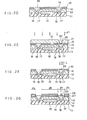
- an n-type silicon layer 12 is epitaxially grown, 2 to 3 Ak m thick, on a p-type silicon substrate 11 with a principal surface of which the Miller indices are (100), as shown in Figure 2A, and at desired regions at the bottom of the n-type silicon layer 12, a plurality of n -type silicon buried layers 13 of a square or a rectangular shape with their sides in the directions [I10] and [110] are formed.
- These steps are conventional, and a silicon substrate thus formed is conventionally utilized to fabricate bipolar integrated circuits.
- a first silicon dioxide (Si0 2 ) film 14 approximately 1,000 A thick is formed on the substrate, by a known thermal oxidation process for example, and on this first Si0 2 film 14, a first silicon nitride (Si3N4) film 15 approximately 2,500 A thick is grown, by a conventional chemical vapour-phase deposition for example.
- a window 16 is formed as illustrated in Figure 2B in the first Si 3 N 4 film 15 and the first Si0 2 film 14 under the film 15 for the purpose of subsequently forming a V-groove approximately 6 to 7 ⁇ m wide which will surround the upper regions of each buried layer 13 in the [110] and [110] directions.
- a second silicon dioxide (Si0 2 ) film 18 approximately 0.5 ⁇ m thick is formed by a known process on the internal surface of the V-groove 17. Thereafter, a high purity polycrystal silicon layer 19 approximately 6 to 7 ⁇ m thick is grown on the surface of the substrate by the conventional chemical vapour-phase deposition such that the V-groove 17 is completely filled with polycrystal silicon.
- the substrate is then lapped by a known process to remove polycrystal silicon layer 19 deposited on the substrate and also, as shown in Figure 2D, to expose the Si 3 N 4 film 15 under the layer of polycrystal silicon. Throughout these steps, polycrystal.silicon layer 19 still remains in the V-groove 17.
- a photoresist layer 21 is coated and patterned as depicted in Figure 2E to provide a window 20 for the purpose of subsequently forming an electrically conductive layer of a desired shape .
- Ions of phosphorus (P + ) are ion implanted, with a dosage of 1 x 10 15 cm -2 at an energy of 60 Kev, and the photoresist layer 21 is used as a mask to form in the polycrystal silicon layer 19 in the V - groove 17 an ion implanted layer 22 of n +- type of a desired shape having a depth of approximately 0.15 ⁇ m.
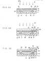
- the photoresist layer 21 on the substrate is removed using a conventional technique, and as illustrated in Figure 2F, the ion implanted layer 22 is irradiated by a Q switch ruby laser beam L having a power density of 10 7 to 10 8 w/cm 2 for a short period of time, typically 20 to 50 ns, to anneal the layer 22 according to a given pattern to fabricate n -type single-crystal silicon conductive layer 23.
- a Q switch ruby laser beam L having a power density of 10 7 to 10 8 w/cm 2 for a short period of time, typically 20 to 50 ns
- a fourth SiO 2 film 28 (see Figure 2H) which is about 1 ⁇ m thick is formed by conventional thermal oxidation on the surface of polycrystal silicon layer 19 including the conductive layer 23.
- a fourth SiO 2 film 28 see Figure 2H
- a third SiO 2 film 27 approximately 1,000 ⁇ thick and a second Si 3 N 4 film 26, also approximately 1,000 A thick.
- These films are patterned according to a conventional method, and as shown in Figure 2G an oxidation resisting mask layer is formed on a region 24 where a window is to be formed for an electrode contact to the conductive layer 23, the mask layer being comprised of the third Si0 2 film 27 and the second Si 3 N 4 film 26 thereon.
- the oxidation resisting mask layer remains on a region 25 of the substrate where device elements are to be fabricated.
- the substrate undergoes a conventional thermal oxidation to form afourth Si0 2 film 28 approximately 1 ⁇ m thick on the conductive layer 23 and polycrystal silicon layer 19 where not covered by the oxidation resisting mask layer, as illustrated in Fig. 2H.
- the second Si 3 N 4 film 26 is removed and a window 29 for contact to the conductive layer is formed through the thick fourth SiO 2 film 28 on the conductive layer 23, the thin third Si0 2 film 27 being left at the bottom of the window.
- the third SiO 2 film 27 remains on the first Si 3 N 4 film 15 in the region 25 where device elements are to be fabricated.
- devices such as transistors (not shown) are fabricated in the epitaxial layer in the region 25 according to a conventional method, and as depicted in Figure 21, the substrate is coated with an insulation layer 30 of phospho-silicate-glass (PSG) for example.
- PSG phospho-silicate-glass
- a window 31 for a wiring connection to the conductive layer 23 formed in the polycrystal layer 19 in V-groove 17 for establishing an interconnecting path between electrodes of device elements is formed simultaneously with the opening of windows (not shown) for other electrode contacts to each functional layer of semiconductor device elements fabricated through insulating protective layers 30, 27, 15 and 14.
- a metal wiring layer 32 of aluminium for example is fabricated in contact with the conductive layer 23 in the contact window 31 in a manner known to the person skilled in the art.
- An electrically conductive layer or wiring layer for interconnecting the electrodes of the devices, in a V-groove isolation region prepared in accordance with the method described above is formed of single-crystal silicon doped with impurity material, so that its electrical resistance is extremely low. Further, since this conductive layer is isolated from the semiconductor device element region (25) by Si0 2 film 18 formed on the internal surface of the V-groove and by the thick high purity polycrystal silicon layer deposited in the V-groove, it shows excellent insulation characteristics and dielectric strength vis-a-vis the device element region. Furthermore, isolation defects due to a parastic MOS effect as experienced with conventional V-groove structure are effectively prevented by the existence of the high resistivity polycrystal silicon layer at the bottom of the V-groove in an embodiment of the invention.
- the V-groove is filled with high purity polycrystal silicon having a high resistance value, then an electrically conductive layer is formed in the polycrystal silicon layer at the surface thereof.
- a polycrystal silicon layer of one conductivity type is employed to fill the V-groove, and in a desired region of the polycrystal silicon layer, which region is of a first conductivity type, a polycrystal silicon region of a second conductivity type, different from the first conductivity type, is formed by means of ion implantation.
- Laser annealing is then carried out to turn a desired region of the polycrystal silicon layer, including the polycrystal silicon region of the second conductivitiy type, into a single-crystal silicon structure.
- a pn-junction is formed in the single-crystal silicon between the region of the single crystal which is of the first conductivity type, which is the same as that of the polycrystal silicon layer in the V-groove, and a conductive layer or wiring layer for inter-connecting the electrodes of the device elements which is comprised of the single-crystal silicon region of the second conductivity type.
- High resistance value of the pn-junction in the reverse direction is utilized to ensure a high degree of insulation between the conductive layer or wiring layer for connecting the electrodes and the device region, and to prevent parastic MOS transistor action at the bottom of the V-groove.
- photoresist is coated and patterned as shown in Figure 3B in the same manner as was explained with reference to Figure 2E to provide a window 20.
- Ions of phosphorus (P + ) are implanted with a dosage of 1 x 10 15 cm -2 under an accelerating energy of 60 KeV, using the photoresist layer 21 as a mask to form in the polycrystal silicon layer 19 in the V-groove 17 an ion implanted layer 22 of n +- type of a desired shape and having a depth of approximately 0.15 ⁇ m.
- An embodiment of this invention provides a method of fabricating a semiconductor device having a V-groove insulating isolation structure in which the groove is filled with polycrystal silicon and the internal surface of the groove is covered with an insulating film of silicon dioxide, the method comprising selectively ion implanting an impurity material into a desired region of the polycrystal silicon layer in order to give this desired region a desired different type of electric conductivity relative to the polycrystal silicon layer, followed by selectively annealing, by an energy beam such as laser beam, a desired part of the polycrystal silicon layer including the region into which the impurity material has been ion implanted.
Landscapes
- Engineering & Computer Science (AREA)
- Physics & Mathematics (AREA)
- Power Engineering (AREA)
- Microelectronics & Electronic Packaging (AREA)
- Computer Hardware Design (AREA)
- Condensed Matter Physics & Semiconductors (AREA)
- General Physics & Mathematics (AREA)
- Manufacturing & Machinery (AREA)
- High Energy & Nuclear Physics (AREA)
- Optics & Photonics (AREA)
- Toxicology (AREA)
- Health & Medical Sciences (AREA)
- Electromagnetism (AREA)
- Chemical & Material Sciences (AREA)
- Crystallography & Structural Chemistry (AREA)
- Element Separation (AREA)
- Internal Circuitry In Semiconductor Integrated Circuit Devices (AREA)
- Recrystallisation Techniques (AREA)
Abstract
Description
- This invention relates to a semiconductor device with a V-groove insulating isolation structure, and a method of manufacturing such a device, and more particularly to an insulating isolation structure, and the formation thereof, in a semiconductor device.
- In the manufacture of bipolar semiconductor integrated circuit devices, efforts have been made in relation to the fabrication of isolation layers or regions in various devices with a view to increasing density of the integrated circuits by adopting insulating isolation of a V-groove structure, which has the merits of decreasing the area exclusively occupied by means given over to isolation purposes, as compared with a casein which an isolation layer is prepared in accordance with the known art, and of eliminating adverse effects on tbeperformance of the devices, which occur when an isolation layer and a functional layer of a device are arranged close to one another.
- An example of a known insulating isolation V-groove structure is shown in a cross-sectional view in Figure 1 of the accompanying drawings. In a silicon substrate of a two layer structure comprising an n-type silicon
epitaxial layer 2 formed on a p-type silicon substrate 1, there is formed a V-groove 4, the surface of which is covered with a silicon dioxide (Si02)film 3, which penetrates through the n-type silicon layer 2 and enters into the p-type silicon substrate 1. The V-groove is filled with high purity polycrystal silicon having a high specific resistance, and a thick silicon dioxide (Si02,) film 3', which is usually 5 to 6 flm wide, is formed on the protruding surface ofpolycrystal silicon 5. Aninsulating film 6 is formed on the surface of n-type silicon layer 2. - Although this known insulating isolation layer structure is formed of poiycrystal silicon the structure has been used only for the purpose of insulating isolation and for no other purposes whatsoever. Attempts were made to confer electric conductivity on the polycrystal silicon in the V-groove, which occupies considerable area of the substrate, and to utilize the insulating isolation layer structure as part of wiring layers interconnecting electrodes of a device, with a view to further increasing integration density.
- However, in various methods proposed for filling the V-
groove 4 of the structure as shown in Figure 1, of which the internal surface is covered with Si02 film 3, with n-type or p-type electrically conductive polycrystal silicon by means of chemical vapour-phase deposition (CVD), many technical problems have to be faced due to the facts that electrically conductive polycrystal silicon in the V-groove runs continuously throughout the entire surface of the substrate, specific resistance of the polycrystal silicon layer cannot be made too low, isolation becomes incomplete when a high electric potential is applied to the polycrystal silicon layer due to the formation of a channel in a metal-oxide- semiconductor (MOS) fashion in the p-type silicon substrate around the edge of the V-groove and the fact that Si02 film interposed between the polycrystal silicon layer and the silicon layer of the substrate is relatively thin. An attempt to positively utilize the insulating isolation layer as a wiring layer interconnecting device electrodes has not been put into practice in manufacturing bipolar integrated circuit devices. - According to one aspect of the present invention there is provided a semiconductor device having a V-groove insulating isolation structure, in which an insulating film is formed on the surface of the groove and the groove is filled with polycrystal semiconductor, characterised in that a single crystal semiconductor region is formed in the polycrystal semiconductor, for forming a conductive path in the groove.
- According to another'aspect of the present invention, there is provided a method of manufacturing a semiconductor device having a V-groove insulating isolation structure, in which an insulating film is formed on the surface of the groove and the groove is filled with polycrystal semiconductor, characterised by forming a single crystal semiconductor region in the polycrystal semiconductor for forming a conductive path in the groove.
- In arriving at the present invention, the problems enumerated above have been fully reviewed, and a semiconductor device and a method of manufacturing the same are offered by embodiments of the present invention such that a wiring layer connecting electrodes relies upon a polycrystal silicon layer in a restricted and desired region in an insulating isolation layer of V-groove structure, the wiring layer of polycrystal silicon exhibiting excellent performance in the insulation of a device and also having a very high electric conductivity, with a view to improving integration density of the semiconductor device further.
- A semiconductor device embodying the present invention comprises:
- a semiconductor substrate of a first conductivity type, a semiconductor layer of a second conductivity type, opposite to the first conductivity type, the layer being formed on the substrate, a V-groove penetrating through the semiconductor layer and into the substrate, an insulating film formed on the surface of the V-groove, a polycrystal semiconductor layer formed in the V-groove on the insulating film, a single crystal semiconductor region formed at a surface portion of the polycrystal semiconductor layer for forming an interconnecting path between device elements formed in the semiconductor layer, and a metal wiring layer formed in contact with the single crystal semiconductor region.
- In the above semiconductor device, the polycrystal semiconductor layer preferably has a high specific resistance. Furthermore, in the above semiconductor device, the single crystal semiconductor region preferably has a first region of one conductivity type and a second region of the other conductivity type to form a PN junction therebetween, the first region being formed in the second region and forming the interconnecting path, the second region electrically isolating the first region from the polycrystal silicon layer.
- .A method of manufacturing a semiconductor device embodying the present invention comprises the steps of:
- preparing a semiconductor substrate of a first conductivity type having a semiconductor layer of a second conductivity type, opposite to the first conductivity type, the layer being formed on the substrate, forming a V-groove penetrating through the semiconductor layer and into the substrate, forming an insulating film on the surface of the V-groove, forming a polycrystal semiconductor layer on the insulating film in the V-groove, and irradiating a surface portion of the polycrystal semiconductor layer with an energy beam to convert that portion to a single crystal region for an interconnecting path between device elements to be formed in the semiconductor layer.
- In the above method of manufacturing a semiconductor device the energy beam may be a laser beam.
- Preferably, the above method further comprises the step of implanting impurity ions into the polycrystal semiconductor layer at the said surface portion before the step of irradiating with an energy beam.
- A specific method of manufacturing a semiconductor device embodying this invention comprises the steps of:
- forming an isolation layer of V-groove structure, for electrially isolating device elements from one another, in a semiconductor substrate having a first semiconductor layer, of one conductivity type, which first layer has a principal face with Miller indices (100), and having a second semiconductor layer on the first semiconductor layer, which second layer is of a conductivity type different from that of the first semiconductor layer, and has a principal face with Miller indices (100), the V-groove penetrating through the second semiconductor layer and extending into the first semiconductor layer, forming an insulating film on the internal surface of the V-groove, forming a polycrystal silicon layer of high purity or of a desired electric conductivity type on the semiconductor substrate in such a manner that polycrystal silicon fills the V-groove and covers the entire surface of the substrate, removing the polycrystal silicon layer from the surface of the substrate in such a way that polycrystal silicon remains only in the V-groove,
- either,selectively doping impurity material into the layer of polycrystal silicon of high purity in the V-groove to render a desired region thereof p-type or n-type in electric conductivity,
- or,selectively doping impurity material into the layer of polycrystal silicon of a desired conductivity type in the V-groove to give a desired region thereof an electric conductivity of a type which is different from the said desired conductivity type, and
- selectively annealing a selected region of the polycrystal silicon layer, which selected region includes that region of the polycrystal silicon layer into which the impurity material has been implanted.
- Another method of manufacturing a semiconductor device embodying this invention comprises the steps of:
- filling the V-groove with polycrystal silicon of a first conductivity type to form a polycrystal silicon layer, forming in the polycrystal silicon layer a region of a second conductivity type which is different from the first conductivity type, and
- annealing by laser beam to turn a desired region of the polycrystal silicon layer, including the region of the second conductivity type, into a single-crystal silicon region, thereby to form a junction between the first conductivity type and the second conductivity type in the single-crystal silicon region, the region of the second conductivity type being for interconnecting electrodes of device elements.
- In a further method embodying this invention, after removal of polycrystal silicon layer from the surface of the substrate to leave polycrystal silicon only in the V-groove, as mentioned above, dopant material such as boron is ion implanted into the polycrystal silicon layer in the V-groove to form a shallow p-type polycrystal silicon layer.
- Reference is made, by way of example, to the accompanying drawings, in which:-
- Figure 1 is a cross-sectional view illustrating an insulation isolation layer of a V-groove structure according to the prior art,
- Figures 2A to 2J are cross-sectional views illustrating respective steps involved in a method embodying the present invention, and
- Figures 3A to 3C are cross-sectional views illustrating respective steps involved in another method embodying the present invention.
- In Figures 2A to 2J and 3A to 3C like parts are designated by like reference numerals.
- In a method embodying this invention and illustrated by Figures 2A to 2J, an n-
type silicon layer 12 is epitaxially grown, 2 to 3 Akm thick, on a p-type silicon substrate 11 with a principal surface of which the Miller indices are (100), as shown in Figure 2A, and at desired regions at the bottom of the n-type silicon layer 12, a plurality of n -type silicon buriedlayers 13 of a square or a rectangular shape with their sides in the directions [I10] and [110] are formed. These steps are conventional, and a silicon substrate thus formed is conventionally utilized to fabricate bipolar integrated circuits. - A first silicon dioxide (Si02)
film 14 approximately 1,000 A thick is formed on the substrate, by a known thermal oxidation process for example, and on this first Si02 film 14, a first silicon nitride (Si3N4)film 15 approximately 2,500 A thick is grown, by a conventional chemical vapour-phase deposition for example. Using a known process such as photolithographic etching, awindow 16 is formed as illustrated in Figure 2B in the first Si3N4 film 15 and the first Si02 film 14 under thefilm 15 for the purpose of subsequently forming a V-groove approximately 6 to 7 µ m wide which will surround the upper regions of each buriedlayer 13 in the [110] and [110] directions. - These steps are followed by anisotropic etching of the silicon layer exposed through the
window 16 for forming the V-groove, using anisotropic etchant containing potassium hydroxide (KOH) for example. There is formed in the substrate at the periphery of the buried layer 13 a V-groove 17 penetrating through the n-type silicon layer 12 and reaching into the p-type silicon substrate 11. - Next, as depicted in Figure 2C, a second silicon dioxide (Si02)
film 18 approximately 0.5 µm thick is formed by a known process on the internal surface of the V-groove 17. Thereafter, a high puritypolycrystal silicon layer 19 approximately 6 to 7 µm thick is grown on the surface of the substrate by the conventional chemical vapour-phase deposition such that the V-groove 17 is completely filled with polycrystal silicon. - The substrate is then lapped by a known process to remove
polycrystal silicon layer 19 deposited on the substrate and also, as shown in Figure 2D, to expose the Si3N4 film 15 under the layer of polycrystal silicon. Throughout these steps,polycrystal.silicon layer 19 still remains in the V-groove 17. - Further, a
photoresist layer 21 is coated and patterned as depicted in Figure 2E to provide awindow 20 for the purpose of subsequently forming an electrically conductive layer of a desired shape . Ions of phosphorus (P+) are ion implanted, with a dosage of 1 x 1015 cm-2 at an energy of 60 Kev, and thephotoresist layer 21 is used as a mask to form in thepolycrystal silicon layer 19 in the V-groove 17 an ion implantedlayer 22 of n+-type of a desired shape having a depth of approximately 0.15 µm. - Here, the
photoresist layer 21 on the substrate is removed using a conventional technique, and as illustrated in Figure 2F, the ion implantedlayer 22 is irradiated by a Q switch ruby laser beam L having a power density of 107 to 108 w/cm2 for a short period of time, typically 20 to 50 ns, to anneal thelayer 22 according to a given pattern to fabricate n -type single-crystal siliconconductive layer 23. Thereafter, in order to ensure the insulation of the surfaces of theconductive layer 23 andpolycrystal silicon layer 19, it is desired that a fourth SiO2 film 28 (see Figure 2H) which is about 1 µm thick is formed by conventional thermal oxidation on the surface ofpolycrystal silicon layer 19 including theconductive layer 23. As will be understood by those skilled in the art, it is not easy to form in such a thick SiO2 film a window for contact to theconductive layer 23 in a later process step. Therefore, processes subsequent to the completion of theconductive layer 23 are carried out in a manner described below. - Employing a conventional chemical vapour-phase deposition technique, there is grown on the substrate a third SiO2 film 27 approximately 1,000 Å thick and a second Si3N4 film 26, also approximately 1,000 A thick. These films are patterned according to a conventional method, and as shown in Figure 2G an oxidation resisting mask layer is formed on a
region 24 where a window is to be formed for an electrode contact to theconductive layer 23, the mask layer being comprised of the third Si02 film 27 and the second Si3N4 film 26 thereon. Throughout the process just described, the oxidation resisting mask layer remains on aregion 25 of the substrate where device elements are to be fabricated. - Then, the substrate undergoes a conventional thermal oxidation to form afourth Si02 film 28 approximately 1 µm thick on the
conductive layer 23 andpolycrystal silicon layer 19 where not covered by the oxidation resisting mask layer, as illustrated in Fig. 2H. Subsequent to this, the second Si3N4 film 26 is removed and awindow 29 for contact to the conductive layer is formed through the thick fourth SiO2 film 28 on theconductive layer 23, the thin third Si02 film 27 being left at the bottom of the window. During the above-described process, the third SiO2film 27 remains on the first Si3N4film 15 in theregion 25 where device elements are to be fabricated. - Thereafter, devices such as transistors (not shown) are fabricated in the epitaxial layer in the
region 25 according to a conventional method, and as depicted in Figure 21, the substrate is coated with aninsulation layer 30 of phospho-silicate-glass (PSG) for example. Further utilizing a conventional technique, awindow 31 for a wiring connection to theconductive layer 23 formed in thepolycrystal layer 19 in V-groove 17 for establishing an interconnecting path between electrodes of device elements is formed simultaneously with the opening of windows (not shown) for other electrode contacts to each functional layer of semiconductor device elements fabricated through insulatingprotective layers - Then, as illustrated in Figure 2J, a
metal wiring layer 32 of aluminium for example is fabricated in contact with theconductive layer 23 in thecontact window 31 in a manner known to the person skilled in the art. - An electrically conductive layer or wiring layer for interconnecting the electrodes of the devices, in a V-groove isolation region prepared in accordance with the method described above is formed of single-crystal silicon doped with impurity material, so that its electrical resistance is extremely low. Further, since this conductive layer is isolated from the semiconductor device element region (25) by Si02 film 18 formed on the internal surface of the V-groove and by the thick high purity polycrystal silicon layer deposited in the V-groove, it shows excellent insulation characteristics and dielectric strength vis-a-vis the device element region. Furthermore, isolation defects due to a parastic MOS effect as experienced with conventional V-groove structure are effectively prevented by the existence of the high resistivity polycrystal silicon layer at the bottom of the V-groove in an embodiment of the invention.
- In the foregoing embodiment of the invention, the V-groove is filled with high purity polycrystal silicon having a high resistance value, then an electrically conductive layer is formed in the polycrystal silicon layer at the surface thereof. In a second embodiment of this invention, however, a polycrystal silicon layer of one conductivity type is employed to fill the V-groove, and in a desired region of the polycrystal silicon layer, which region is of a first conductivity type, a polycrystal silicon region of a second conductivity type, different from the first conductivity type, is formed by means of ion implantation. Laser annealing is then carried out to turn a desired region of the polycrystal silicon layer, including the polycrystal silicon region of the second conductivitiy type, into a single-crystal silicon structure. By this annealing step a pn-junction is formed in the single-crystal silicon between the region of the single crystal which is of the first conductivity type, which is the same as that of the polycrystal silicon layer in the V-groove, and a conductive layer or wiring layer for inter-connecting the electrodes of the device elements which is comprised of the single-crystal silicon region of the second conductivity type. High resistance value of the pn-junction in the reverse direction is utilized to ensure a high degree of insulation between the conductive layer or wiring layer for connecting the electrodes and the device region, and to prevent parastic MOS transistor action at the bottom of the V-groove.
- In a third embodiment of the invention, steps explained above with reference to Figures 2A to 2D are carried out in exactly the same manner.
- Then, as illustrated in Figure 3A, dopant material, boron for example, is ion implanted by a conventional method into the
polycrystal silicon layer 19 in the V-groove to form a shallow p-typepolycrystal silicon layer 33. - Thereafter, photoresist is coated and patterned as shown in Figure 3B in the same manner as was explained with reference to Figure 2E to provide a
window 20. Ions of phosphorus (P+) are implanted with a dosage of 1 x 1015 cm-2 under an accelerating energy of 60 KeV, using thephotoresist layer 21 as a mask to form in thepolycrystal silicon layer 19 in the V-groove 17 an ion implantedlayer 22 of n+-type of a desired shape and having a depth of approximately 0.15 µm. - These steps are followed by those explained above with reference to Figures 2F to 2I. After a
metal wiring layer 32 of aluminium for example is fabricated in thecontact window 31 in a conventional manner, the structure is as illustrated in Figure 3C. - In the foregoing description of a method embodying this invention, a laser beam is used for annealing a layer implanted with ions of impurity material. As will be apparent to a person skilled in the art, an electron beam may alternatively be utilized for the annealing to attain the same result.
- As will be understood from the description of embodiments of the present invention given above, a method embodying this invention makes it possible to form, at a surface portion of a V-groove, for isolation of device element regions, a wiring layer for interconnection of electrodes, which layer is of low electric resistance, without impairing the isolation characteristics of the V-groove between device elements. This contributes to increasing integration density of integrated circuits such as bipolar integrated circuits.
- An embodiment of this invention provides a method of fabricating a semiconductor device having a V-groove insulating isolation structure in which the groove is filled with polycrystal silicon and the internal surface of the groove is covered with an insulating film of silicon dioxide, the method comprising selectively ion implanting an impurity material into a desired region of the polycrystal silicon layer in order to give this desired region a desired different type of electric conductivity relative to the polycrystal silicon layer, followed by selectively annealing, by an energy beam such as laser beam, a desired part of the polycrystal silicon layer including the region into which the impurity material has been ion implanted.
- Thus, an embodiment of the present invention provides a semiconductor device having a V-groove insulating isolation structure, in which an insulating film is formed on the surface of the groove and the groove is filled with polycrystal semiconductor, characterised in that a selected region of the polycrystal semiconductor is annealed for forming a conductive path in the groove.
- Moreover, an embodiment of the present invention provides al.method of manufacturing a semiconductor device having a V-groove insulating isolation structure in which an insulating film is formed on the surface of the groove and the groove is filled with polycrystal semiconductor, characterised by annealing a selected region of the polycrystal semiconductor for forming a conductive path in the groove.
Claims (10)
Applications Claiming Priority (2)
| Application Number | Priority Date | Filing Date | Title |
|---|---|---|---|
| JP3807080A JPS56146247A (en) | 1980-03-25 | 1980-03-25 | Manufacture of semiconductor device |
| JP38070/80 | 1980-03-25 |
Publications (3)
| Publication Number | Publication Date |
|---|---|
| EP0036764A2 true EP0036764A2 (en) | 1981-09-30 |
| EP0036764A3 EP0036764A3 (en) | 1984-01-18 |
| EP0036764B1 EP0036764B1 (en) | 1986-11-20 |
Family
ID=12515223
Family Applications (1)
| Application Number | Title | Priority Date | Filing Date |
|---|---|---|---|
| EP81301189A Expired EP0036764B1 (en) | 1980-03-25 | 1981-03-19 | A semiconductor device with a v-groove insulating isolation structure and a method of manufacturing such a device |
Country Status (5)
| Country | Link |
|---|---|
| US (1) | US4497665A (en) |
| EP (1) | EP0036764B1 (en) |
| JP (1) | JPS56146247A (en) |
| DE (1) | DE3175640D1 (en) |
| IE (1) | IE52351B1 (en) |
Cited By (2)
| Publication number | Priority date | Publication date | Assignee | Title |
|---|---|---|---|---|
| EP0086915A2 (en) * | 1981-11-20 | 1983-08-31 | Fujitsu Limited | Semiconductor device having conductor lines connecting the elements |
| DE3825547A1 (en) * | 1987-09-08 | 1989-03-16 | Mitsubishi Electric Corp | CONNECTING LAYER ON BURNED DIELECTRIC AND METHOD FOR PRODUCING SUCH A |
Families Citing this family (6)
| Publication number | Priority date | Publication date | Assignee | Title |
|---|---|---|---|---|
| JPS59155944A (en) * | 1983-02-25 | 1984-09-05 | Mitsubishi Electric Corp | Manufacture of semiconductor device |
| US4610730A (en) * | 1984-12-20 | 1986-09-09 | Trw Inc. | Fabrication process for bipolar devices |
| US4849371A (en) * | 1986-12-22 | 1989-07-18 | Motorola Inc. | Monocrystalline semiconductor buried layers for electrical contacts to semiconductor devices |
| CN1034228C (en) * | 1993-08-04 | 1997-03-12 | 株洲冶炼厂 | Iron-removing process by solvent extraction |
| DE19538005A1 (en) * | 1995-10-12 | 1997-04-17 | Fraunhofer Ges Forschung | Method of creating trench isolation in a substrate |
| US20110241185A1 (en) * | 2010-04-05 | 2011-10-06 | International Business Machines Corporation | Signal shielding through-substrate vias for 3d integration |
Citations (3)
| Publication number | Priority date | Publication date | Assignee | Title |
|---|---|---|---|---|
| US3956033A (en) * | 1974-01-03 | 1976-05-11 | Motorola, Inc. | Method of fabricating an integrated semiconductor transistor structure with epitaxial contact to the buried sub-collector |
| DE2837800A1 (en) * | 1978-08-30 | 1980-03-13 | Philips Patentverwaltung | Wiring pattern prodn. on semiconductor - by ion implantation doping of amorphous layer and selective conversion to polycrystalline form by intense light |
| EP0030286A2 (en) * | 1979-11-23 | 1981-06-17 | Alcatel N.V. | Dielectrically insulated semiconductor component and process for its manufacture |
Family Cites Families (8)
| Publication number | Priority date | Publication date | Assignee | Title |
|---|---|---|---|---|
| US4037306A (en) * | 1975-10-02 | 1977-07-26 | Motorola, Inc. | Integrated circuit and method |
| US4048649A (en) * | 1976-02-06 | 1977-09-13 | Transitron Electronic Corporation | Superintegrated v-groove isolated bipolar and vmos transistors |
| JPS5534442A (en) * | 1978-08-31 | 1980-03-11 | Fujitsu Ltd | Preparation of semiconductor device |
| US4214918A (en) * | 1978-10-12 | 1980-07-29 | Stanford University | Method of forming polycrystalline semiconductor interconnections, resistors and contacts by applying radiation beam |
| US4269636A (en) * | 1978-12-29 | 1981-05-26 | Harris Corporation | Method of fabricating self-aligned bipolar transistor process and device utilizing etching and self-aligned masking |
| JPS6043024B2 (en) * | 1978-12-30 | 1985-09-26 | 富士通株式会社 | Manufacturing method of semiconductor device |
| US4295924A (en) * | 1979-12-17 | 1981-10-20 | International Business Machines Corporation | Method for providing self-aligned conductor in a V-groove device |
| US4260436A (en) * | 1980-02-19 | 1981-04-07 | Harris Corporation | Fabrication of moat resistor ram cell utilizing polycrystalline deposition and etching |
-
1980
- 1980-03-25 JP JP3807080A patent/JPS56146247A/en active Granted
-
1981
- 1981-03-19 EP EP81301189A patent/EP0036764B1/en not_active Expired
- 1981-03-19 DE DE8181301189T patent/DE3175640D1/en not_active Expired
- 1981-03-20 IE IE631/81A patent/IE52351B1/en unknown
-
1983
- 1983-01-03 US US06/455,327 patent/US4497665A/en not_active Expired - Fee Related
Patent Citations (3)
| Publication number | Priority date | Publication date | Assignee | Title |
|---|---|---|---|---|
| US3956033A (en) * | 1974-01-03 | 1976-05-11 | Motorola, Inc. | Method of fabricating an integrated semiconductor transistor structure with epitaxial contact to the buried sub-collector |
| DE2837800A1 (en) * | 1978-08-30 | 1980-03-13 | Philips Patentverwaltung | Wiring pattern prodn. on semiconductor - by ion implantation doping of amorphous layer and selective conversion to polycrystalline form by intense light |
| EP0030286A2 (en) * | 1979-11-23 | 1981-06-17 | Alcatel N.V. | Dielectrically insulated semiconductor component and process for its manufacture |
Non-Patent Citations (1)
| Title |
|---|
| APPLIED PHYSICS LETTERS, vol. 34, no. 11, June 1979, pages 737-739, New York, USA C.P. WU et al.: "Pulsed laser annealing of ion-implanted polycrystalline silicon films" * |
Cited By (4)
| Publication number | Priority date | Publication date | Assignee | Title |
|---|---|---|---|---|
| EP0086915A2 (en) * | 1981-11-20 | 1983-08-31 | Fujitsu Limited | Semiconductor device having conductor lines connecting the elements |
| EP0086915A3 (en) * | 1981-11-20 | 1985-12-18 | Fujitsu Limited | Semiconductor device having conductor lines connecting the elements |
| DE3825547A1 (en) * | 1987-09-08 | 1989-03-16 | Mitsubishi Electric Corp | CONNECTING LAYER ON BURNED DIELECTRIC AND METHOD FOR PRODUCING SUCH A |
| US5041898A (en) * | 1987-09-08 | 1991-08-20 | Mitsubishi Denki Kabushiki Kaisha | Interconnection layer formed on embedded dielectric and method for manufacturing the same |
Also Published As
| Publication number | Publication date |
|---|---|
| JPS6227744B2 (en) | 1987-06-16 |
| JPS56146247A (en) | 1981-11-13 |
| EP0036764B1 (en) | 1986-11-20 |
| IE52351B1 (en) | 1987-09-30 |
| IE810631L (en) | 1981-09-25 |
| US4497665A (en) | 1985-02-05 |
| EP0036764A3 (en) | 1984-01-18 |
| DE3175640D1 (en) | 1987-01-08 |
Similar Documents
| Publication | Publication Date | Title |
|---|---|---|
| EP0090111B1 (en) | Method of manufacturing a semiconductor device comprising a dielectric isolation region | |
| US4740480A (en) | Method for forming a semiconductor device with trench isolation structure | |
| EP0139371B1 (en) | Process for manufacturing a mos integrated circuit employing a method of forming refractory metal silicide areas | |
| EP0134166B1 (en) | Wafer fabrication by implanting through protective layer | |
| EP0083816B1 (en) | Semiconductor device having an interconnection pattern | |
| EP0176747B1 (en) | Silicon semiconductor substrate with an insulating layer embedded therein and method for forming the same | |
| US4422885A (en) | Polysilicon-doped-first CMOS process | |
| KR100227766B1 (en) | Semiconductor device and the manufacturing method thereof | |
| US4593459A (en) | Monolithic integrated circuit structure and method of fabrication | |
| US4948742A (en) | Method of manufacturing a semiconductor device | |
| EP0272453A2 (en) | Merged bipolar/CMOS technology using electrically active trench | |
| EP0055521B1 (en) | Method of filling a groove in a semiconductor substrate | |
| JPH0754825B2 (en) | Partial dielectric isolation semiconductor device | |
| US4486266A (en) | Integrated circuit method | |
| JPH0719838B2 (en) | Semiconductor device and manufacturing method thereof | |
| CA1045724A (en) | Method for forming integrated circuit regions defined by recessed dielectric isolation | |
| US4648909A (en) | Fabrication process employing special masks for the manufacture of high speed bipolar analog integrated circuits | |
| EP0036764B1 (en) | A semiconductor device with a v-groove insulating isolation structure and a method of manufacturing such a device | |
| US4409609A (en) | Semiconductor device and method of manufacturing the same | |
| JPH04363046A (en) | Manufacture of semiconductor device | |
| US4633290A (en) | Monolithic CMOS integrated circuit structure with isolation grooves | |
| JPS5992546A (en) | Bipolar integrated circuit device | |
| EP0112662A1 (en) | Stacked MOS devices with polysilicon interconnects | |
| JPH081927B2 (en) | Method for manufacturing substrate structure of semiconductor device | |
| JPH0249020B2 (en) |
Legal Events
| Date | Code | Title | Description |
|---|---|---|---|
| PUAI | Public reference made under article 153(3) epc to a published international application that has entered the european phase |
Free format text: ORIGINAL CODE: 0009012 |
|
| AK | Designated contracting states |
Designated state(s): DE FR GB NL |
|
| RBV | Designated contracting states (corrected) |
Designated state(s): DE FR GB NL |
|
| PUAL | Search report despatched |
Free format text: ORIGINAL CODE: 0009013 |
|
| AK | Designated contracting states |
Designated state(s): DE FR GB NL |
|
| 17P | Request for examination filed |
Effective date: 19840611 |
|
| GRAA | (expected) grant |
Free format text: ORIGINAL CODE: 0009210 |
|
| AK | Designated contracting states |
Kind code of ref document: B1 Designated state(s): DE FR GB |
|
| ET | Fr: translation filed | ||
| REF | Corresponds to: |
Ref document number: 3175640 Country of ref document: DE Date of ref document: 19870108 |
|
| PLBE | No opposition filed within time limit |
Free format text: ORIGINAL CODE: 0009261 |
|
| STAA | Information on the status of an ep patent application or granted ep patent |
Free format text: STATUS: NO OPPOSITION FILED WITHIN TIME LIMIT |
|
| 26N | No opposition filed | ||
| PGFP | Annual fee paid to national office [announced via postgrant information from national office to epo] |
Ref country code: GB Payment date: 19910215 Year of fee payment: 11 |
|
| PGFP | Annual fee paid to national office [announced via postgrant information from national office to epo] |
Ref country code: FR Payment date: 19910328 Year of fee payment: 11 |
|
| PGFP | Annual fee paid to national office [announced via postgrant information from national office to epo] |
Ref country code: DE Payment date: 19910522 Year of fee payment: 11 |
|
| PG25 | Lapsed in a contracting state [announced via postgrant information from national office to epo] |
Ref country code: GB Effective date: 19920319 |
|
| GBPC | Gb: european patent ceased through non-payment of renewal fee | ||
| PG25 | Lapsed in a contracting state [announced via postgrant information from national office to epo] |
Ref country code: FR Effective date: 19921130 |
|
| PG25 | Lapsed in a contracting state [announced via postgrant information from national office to epo] |
Ref country code: DE Effective date: 19921201 |
|
| REG | Reference to a national code |
Ref country code: FR Ref legal event code: ST |